EP2913502A1 - Procédé de fonctionnement d'un moteur à combustion couplé à un générateur et dispositif permettant de mettre en oeuvre le procédé - Google Patents
Procédé de fonctionnement d'un moteur à combustion couplé à un générateur et dispositif permettant de mettre en oeuvre le procédé Download PDFInfo
- Publication number
- EP2913502A1 EP2913502A1 EP14156990.5A EP14156990A EP2913502A1 EP 2913502 A1 EP2913502 A1 EP 2913502A1 EP 14156990 A EP14156990 A EP 14156990A EP 2913502 A1 EP2913502 A1 EP 2913502A1
- Authority
- EP
- European Patent Office
- Prior art keywords
- torque
- control
- combustion engine
- generator
- internal combustion
- Prior art date
- Legal status (The legal status is an assumption and is not a legal conclusion. Google has not performed a legal analysis and makes no representation as to the accuracy of the status listed.)
- Withdrawn
Links
Images


Classifications
-
- F—MECHANICAL ENGINEERING; LIGHTING; HEATING; WEAPONS; BLASTING
- F02—COMBUSTION ENGINES; HOT-GAS OR COMBUSTION-PRODUCT ENGINE PLANTS
- F02D—CONTROLLING COMBUSTION ENGINES
- F02D29/00—Controlling engines, such controlling being peculiar to the devices driven thereby, the devices being other than parts or accessories essential to engine operation, e.g. controlling of engines by signals external thereto
- F02D29/06—Controlling engines, such controlling being peculiar to the devices driven thereby, the devices being other than parts or accessories essential to engine operation, e.g. controlling of engines by signals external thereto peculiar to engines driving electric generators
-
- F—MECHANICAL ENGINEERING; LIGHTING; HEATING; WEAPONS; BLASTING
- F02—COMBUSTION ENGINES; HOT-GAS OR COMBUSTION-PRODUCT ENGINE PLANTS
- F02B—INTERNAL-COMBUSTION PISTON ENGINES; COMBUSTION ENGINES IN GENERAL
- F02B63/00—Adaptations of engines for driving pumps, hand-held tools or electric generators; Portable combinations of engines with engine-driven devices
- F02B63/04—Adaptations of engines for driving pumps, hand-held tools or electric generators; Portable combinations of engines with engine-driven devices for electric generators
- F02B63/042—Rotating electric generators
-
- F—MECHANICAL ENGINEERING; LIGHTING; HEATING; WEAPONS; BLASTING
- F02—COMBUSTION ENGINES; HOT-GAS OR COMBUSTION-PRODUCT ENGINE PLANTS
- F02D—CONTROLLING COMBUSTION ENGINES
- F02D35/00—Controlling engines, dependent on conditions exterior or interior to engines, not otherwise provided for
- F02D35/02—Controlling engines, dependent on conditions exterior or interior to engines, not otherwise provided for on interior conditions
- F02D35/023—Controlling engines, dependent on conditions exterior or interior to engines, not otherwise provided for on interior conditions by determining the cylinder pressure
- F02D35/024—Controlling engines, dependent on conditions exterior or interior to engines, not otherwise provided for on interior conditions by determining the cylinder pressure using an estimation
-
- F—MECHANICAL ENGINEERING; LIGHTING; HEATING; WEAPONS; BLASTING
- F02—COMBUSTION ENGINES; HOT-GAS OR COMBUSTION-PRODUCT ENGINE PLANTS
- F02D—CONTROLLING COMBUSTION ENGINES
- F02D41/00—Electrical control of supply of combustible mixture or its constituents
- F02D41/02—Circuit arrangements for generating control signals
- F02D41/021—Introducing corrections for particular conditions exterior to the engine
-
- F—MECHANICAL ENGINEERING; LIGHTING; HEATING; WEAPONS; BLASTING
- F02—COMBUSTION ENGINES; HOT-GAS OR COMBUSTION-PRODUCT ENGINE PLANTS
- F02D—CONTROLLING COMBUSTION ENGINES
- F02D41/00—Electrical control of supply of combustible mixture or its constituents
- F02D41/02—Circuit arrangements for generating control signals
- F02D41/04—Introducing corrections for particular operating conditions
- F02D41/08—Introducing corrections for particular operating conditions for idling
- F02D41/083—Introducing corrections for particular operating conditions for idling taking into account engine load variation, e.g. air-conditionning
-
- F—MECHANICAL ENGINEERING; LIGHTING; HEATING; WEAPONS; BLASTING
- F02—COMBUSTION ENGINES; HOT-GAS OR COMBUSTION-PRODUCT ENGINE PLANTS
- F02D—CONTROLLING COMBUSTION ENGINES
- F02D41/00—Electrical control of supply of combustible mixture or its constituents
- F02D41/02—Circuit arrangements for generating control signals
- F02D41/14—Introducing closed-loop corrections
- F02D41/1497—With detection of the mechanical response of the engine
-
- F—MECHANICAL ENGINEERING; LIGHTING; HEATING; WEAPONS; BLASTING
- F02—COMBUSTION ENGINES; HOT-GAS OR COMBUSTION-PRODUCT ENGINE PLANTS
- F02D—CONTROLLING COMBUSTION ENGINES
- F02D41/00—Electrical control of supply of combustible mixture or its constituents
- F02D41/02—Circuit arrangements for generating control signals
- F02D41/14—Introducing closed-loop corrections
- F02D41/1401—Introducing closed-loop corrections characterised by the control or regulation method
- F02D2041/141—Introducing closed-loop corrections characterised by the control or regulation method using a feed-forward control element
-
- F—MECHANICAL ENGINEERING; LIGHTING; HEATING; WEAPONS; BLASTING
- F02—COMBUSTION ENGINES; HOT-GAS OR COMBUSTION-PRODUCT ENGINE PLANTS
- F02D—CONTROLLING COMBUSTION ENGINES
- F02D35/00—Controlling engines, dependent on conditions exterior or interior to engines, not otherwise provided for
- F02D35/02—Controlling engines, dependent on conditions exterior or interior to engines, not otherwise provided for on interior conditions
Definitions
- the invention relates first of all to a method for operating an internal combustion engine coupled to a generator. It further relates to a control and regulating device as a device for carrying out the method.
- Generators that are powered by an internal combustion engine are known per se.
- the internal combustion engine is coupled to an electric generator and the generator is followed by a frequency converter.
- the tendency of such arrangements is lightweight, so that, for example, flywheels, as previously provided to compensate for any speed fluctuations, are avoided if possible, or at least the moving masses are reduced.
- the generator is usually operated at a predetermined or predetermined speed.
- the generator is assigned a speed controller. Based on the speed control, the internal combustion engine and the combustion process taking place there are guided. This can be done according to different criteria. For example, power, efficiency and emission are conceivable.
- a control and regulating device is provided with means for carrying out the operating method described here and below, wherein the Execution of the operating method certain means comprise at least one control unit and a speed controller and wherein by means of the speed controller as a manipulated variable, a target torque can be output.
- a counter torque is calculated as additional torque which is applied to the setpoint torque output by the speed controller. This is calculated on the basis of a measured value recorded in the system.
- the measured value recorded in the system is a pressure measurement recorded on the internal combustion engine, namely a pressure measurement which indicates the pressure in the combustion chamber of the internal combustion engine.
- the counter torque / additional torque is then calculated based on the pressure reading.
- a counter-torque is also calculated as additional torque with which the setpoint torque output by the speed controller is applied.
- no pressure reading recorded in the system is used here. Instead, the calculation of the counter-torque / additional torque takes place by estimating a pressure prevailing in the combustion chamber of the internal combustion engine by means of a thermodynamic model and based on the estimated pressure, the counter-torque / additional torque is calculated.
- a precontrol torque is calculated in the calculation of the additional torque by means of a pilot control block, with which the setpoint torque output by the speed controller is acted upon as additional torque.
- one of the calculated additional torques and the additional torque output by the pilot block are used simultaneously.
- the setpoint torque output by the speed controller is thus acted upon by the additional torque output by the pilot control block and by the additional torque determined on the basis of the measured or estimated pressure in the combustion chamber of the internal combustion engine.
- control and regulating device is characterized in that by means of the control and regulating device in the system, namely the internal combustion engine recorded pressure reading is processed, that based on the pressure reading and by means of the control unit outputable data, namely at least one geometric value, a desired position and kinematics data, the additional torque can be determined and that the desired torque can be acted upon by the additional torque.
- a first alternative embodiment of the open-loop and closed-loop control device is designed and set up for determining an estimated value for the pressure prevailing in the combustion chamber of the internal combustion engine by means of a thermodynamic model comprised by the control and regulating device. namely at least one geometry value, a desired position and kinematics data, the additional torque can be determined and that the desired torque can be acted upon by the additional torque.
- a further alternative embodiment of the control and regulating device is intended and arranged for a pilot control torque to be ascertainable by means of a pilot control block encompassed by the control and regulation device and that the setpoint torque can be acted upon by the pilot control torque as additional torque.
- An embodiment of the control and regulation device which is intended to carry out the method in which one of the calculated additional torques and the additional torque output by the pilot block are used simultaneously, is characterized by a realization of a combination of the above-mentioned corresponding features.
- the invention is also a system with a generator and an internal combustion engine and a control and regulating device with the features described here and below.
- FIG. 1 shows in schematic simplified form the basic structure of a system 10 of the type considered here.
- the system 10 includes an electric motor operated as a generator 12 and an internal combustion engine 14.
- the internal combustion engine 14 is mechanically coupled to the generator 12.
- the crankshaft and a piston 16 are shown.
- the internal combustion engine 14 may comprise more than the piston 16 shown, so for example be designed as a double piston engine.
- the alternating current generated by means of the generator 12 is supplied to a converter (frequency converter) 18 shown here as a rectifier.
- a converter frequency converter
- the originally generated by the internal combustion engine 14 energy can be tapped in the form of electrical energy.
- the system 10 is contemplated as a mobile system for use in, for example, a motor vehicle.
- the system 10 also comes as an emergency generator or the like into consideration.
- a control and regulation device 20 causes a control of the system 10, namely, for example, a speed control of the generator 12.
- a position sensor 22 is assigned.
- a actual position value is available in operation and a time course of the actual position value is a measure of the respective rotational speed of the generator 12.
- an actual position value 23 is available from the position sensor 22 from the position sensor 22 an actual position value 23 as well directly or at least indirectly an actual speed value 24 ( FIG. 2 ) available.
- the internal combustion engine 14 is associated with a pressure sensor 26.
- the pressure sensor 26 is a measured value with respect to a generated during operation of the internal combustion engine 14 in the piston chamber pressure (pressure reading 28) available.
- the pressure reading 28 as well as the actual position value 23 and / or the speed actual value 24 are supplied to the control and regulation device 20. On their basis, a manipulated variable 30 for influencing the system 10 is generated.
- process forces generated by the combustion taking place in the combustion 14 combustion pressure generated by the movement and acceleration of the piston 16 mass forces.
- the process forces are known or can be measured and the approach explained below is based on a linearization of the process forces and a subsequent speed control and / or a precontrol of the process forces and a subsequent speed control.
- FIG. 2 shows the already mentioned control and regulating device 20 with further details, namely with a control unit 32 and a speed controller 34 as functional units within the control and regulating device 20th
- the setpoint speed ⁇ * can be the output value of a total of the system 10 upstream flow controller (not shown).
- the speed controller 34 outputs a desired torque T * as the manipulated variable 30. For linearization is at a speed controller 34 subsequent summation point of the target torque T *, the torque which the generator 12 must apply against the pressure prevailing in the combustion chamber, deducted.
- the actual position ⁇ (rotational position) of the rotor of the generator 12 is known with the actual position 23 recorded by the position sensor 22.
- a respective desired position ⁇ * 40 and an angle-dependent transmission ratio between the rotational position of the rotor and the translational position x of the piston 16 are known.
- the control and regulating device 20 so far comprises a transmission member 42, which on the basis of the desired position ⁇ * 40 a measure of the change in the translational position of the piston 16 in response to the change in the rotational position of the rotor (dx / d ⁇ ) * outputs.
- the transfer function f ( ⁇ *) of the transfer element 42 can be influenced by means of kinematic data 44 that can be output by the control unit 32.
- the respectively output kinematics data 44 are likewise based on a predefined or predefinable parameterization of the control and regulation device 20.
- the pressure measurement taken in the determination of the counter torque T in the form of the pressure measurement value Pist 28 recorded in the system 10 is a feedback of the pressure and represents a total linearization of the system 10.
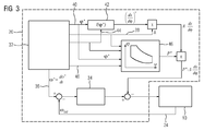
- thermodynamic model 46 go as input values in addition to the current position ⁇ (actual position value 23) or the respective target position ⁇ * 40 of the rotor of the generator 12, the geometry value 38 or other geometry data, the kinematics data 44 and thermodynamics data 48, for example, an information to each in the combustion chamber of the internal combustion engine 14 injected amount of fuel, a.
- the thermodynamic model 46 results in a desired value or an estimated value P * for the pressure in the combustion chamber of the internal combustion engine 14.
- FIG. 4 shows an additional or alternative to the linearization ( FIG. 2 . FIG. 3 ) applicable pilot control of the process forces.
- the pilot control is based on that the mass force of the piston 16 can be calculated from the target position ⁇ * 40 (or the actual position value ⁇ 23) and the angle-dependent gear ratio between the rotational position of the rotor and the position x of the piston 16. In addition, one each current angular acceleration on the rotor known.
- the pre-control block 50 comprises an implementation of the above-described relationship for the determination of the pre-control torque T.
- input values output from the control unit 32 are the respective target position ⁇ * 40 (or the actual position value ⁇ 23), kinematic data 44 and at least with respect to the moved masses a mass information m 52 a.
- FIG. 4 shown embodiment of the control and regulating device 20 is independent of the in FIG. 2 and FIG. 3 shown embodiments.
- the described embodiments can also be combined, for example in the form of a combination of the embodiments in FIG FIG. 2 and FIG. 4 or a combination of the embodiments in FIG. 3 and FIG. 4 ,
- the advantage of a control and regulating device 20 of the type described here is that relieved by the direct control of the process forces of the speed controller 34 is, since otherwise ideally taken into account by the speed controller 34 disturbing forces are eliminated.
- the speed controller 34 is therefore only responsible for implementing an ideal process control on the basis of the predetermined speed of the control unit 32 ⁇ * 36. If in addition to the linearization ( FIG. 2 . FIG. 3 ) also the feedforward according to FIG. 4 is applied, the process control by means of the precontrol and the speed controller 34 has to compensate only small deviations.
- Flywheels can be omitted without reducing the speed stability. This results in a lighter construction and a lower required current for accelerating and decelerating the moving masses.
Landscapes
- Engineering & Computer Science (AREA)
- Chemical & Material Sciences (AREA)
- Combustion & Propulsion (AREA)
- Mechanical Engineering (AREA)
- General Engineering & Computer Science (AREA)
- Control Of Vehicle Engines Or Engines For Specific Uses (AREA)
- Combined Controls Of Internal Combustion Engines (AREA)
- Hybrid Electric Vehicles (AREA)
Priority Applications (6)
| Application Number | Priority Date | Filing Date | Title |
|---|---|---|---|
| EP14156990.5A EP2913502A1 (fr) | 2014-02-27 | 2014-02-27 | Procédé de fonctionnement d'un moteur à combustion couplé à un générateur et dispositif permettant de mettre en oeuvre le procédé |
| EP15702671.7A EP3077649A1 (fr) | 2014-02-27 | 2015-01-21 | Procédé pour faire fonctionner un moteur à combustion interne couplé à un générateur et dispositif pour mettre en uvre le procédé |
| CN201580010908.3A CN106030080B (zh) | 2014-02-27 | 2015-01-21 | 用于操作联接至发生器的内燃机的方法以及用于执行该方法的装置 |
| PCT/EP2015/051136 WO2015128121A1 (fr) | 2014-02-27 | 2015-01-21 | Procédé pour faire fonctionner un moteur à combustion interne couplé à un générateur et dispositif pour mettre en œuvre le procédé |
| CA2940737A CA2940737A1 (fr) | 2014-02-27 | 2015-01-21 | Procede pour faire fonctionner un moteur a combustion interne couple a un generateur et dispositif pour mettre en uvre le procede |
| US15/120,360 US10030591B2 (en) | 2014-02-27 | 2015-01-21 | Operating an internal combustion engine coupled to a generator |
Applications Claiming Priority (1)
| Application Number | Priority Date | Filing Date | Title |
|---|---|---|---|
| EP14156990.5A EP2913502A1 (fr) | 2014-02-27 | 2014-02-27 | Procédé de fonctionnement d'un moteur à combustion couplé à un générateur et dispositif permettant de mettre en oeuvre le procédé |
Publications (1)
| Publication Number | Publication Date |
|---|---|
| EP2913502A1 true EP2913502A1 (fr) | 2015-09-02 |
Family
ID=50193271
Family Applications (2)
| Application Number | Title | Priority Date | Filing Date |
|---|---|---|---|
| EP14156990.5A Withdrawn EP2913502A1 (fr) | 2014-02-27 | 2014-02-27 | Procédé de fonctionnement d'un moteur à combustion couplé à un générateur et dispositif permettant de mettre en oeuvre le procédé |
| EP15702671.7A Withdrawn EP3077649A1 (fr) | 2014-02-27 | 2015-01-21 | Procédé pour faire fonctionner un moteur à combustion interne couplé à un générateur et dispositif pour mettre en uvre le procédé |
Family Applications After (1)
| Application Number | Title | Priority Date | Filing Date |
|---|---|---|---|
| EP15702671.7A Withdrawn EP3077649A1 (fr) | 2014-02-27 | 2015-01-21 | Procédé pour faire fonctionner un moteur à combustion interne couplé à un générateur et dispositif pour mettre en uvre le procédé |
Country Status (5)
| Country | Link |
|---|---|
| US (1) | US10030591B2 (fr) |
| EP (2) | EP2913502A1 (fr) |
| CN (1) | CN106030080B (fr) |
| CA (1) | CA2940737A1 (fr) |
| WO (1) | WO2015128121A1 (fr) |
Cited By (2)
| Publication number | Priority date | Publication date | Assignee | Title |
|---|---|---|---|---|
| WO2022268782A1 (fr) * | 2021-06-22 | 2022-12-29 | Rolls-Royce Solutions GmbH | Dispositif de régulation pour réguler un système de puissance comprenant un moteur à combustion interne et un générateur en liaison fonctionnelle d'entraînement avec le moteur à combustion interne, système de régulation comprenant un tel dispositif de régulation, système de puissance et procédé pour réguler un système de puissance |
| WO2022268781A1 (fr) * | 2021-06-22 | 2022-12-29 | Rolls-Royce Solutions GmbH | Dispositif de régulation pour réguler un système de puissance comprenant un moteur à combustion interne et un générateur en liaison fonctionnelle d'entraînement avec le moteur à combustion interne, système de régulation comprenant un tel dispositif de régulation, système de puissance et procédé pour réguler un système de puissance |
Families Citing this family (7)
| Publication number | Priority date | Publication date | Assignee | Title |
|---|---|---|---|---|
| WO2018100075A1 (fr) | 2016-12-01 | 2018-06-07 | Siemens Aktiengesellschaft | Refroidissement à deux phases pour un système d'entraînement électrique |
| DE102017212798A1 (de) | 2017-07-26 | 2019-01-31 | Siemens Aktiengesellschaft | Elektromotor mit Kühleinrichtung |
| DE102017223800A1 (de) | 2017-12-27 | 2019-06-27 | Siemens Aktiengesellschaft | Kühlung eines Rotors einer elektrischen Maschine |
| DE102018100541B3 (de) * | 2018-01-11 | 2019-07-11 | Mtu Friedrichshafen Gmbh | Verfahren zur Steuerung und Regelung einer Brennkraftmaschine mit Generator und Asynchronmaschine, Steuer- und Regeleinrichtung für eine Brennkraftmaschine mit Generator und Asynchronmaschine sowie Brennkraftmaschine mit Generator und Asynchronmaschine |
| DE102018205623A1 (de) | 2018-04-13 | 2019-10-17 | Siemens Aktiengesellschaft | Statorzahnsystem |
| DE102018211459B4 (de) | 2018-07-11 | 2021-10-21 | Rolls-Royce Deutschland Ltd & Co Kg | Luftfahrzeug-Antriebssystem |
| CN109944707B (zh) * | 2019-05-06 | 2021-10-01 | 徐州徐工挖掘机械有限公司 | 一种提高挖掘机燃油经济性的控制方法 |
Citations (7)
| Publication number | Priority date | Publication date | Assignee | Title |
|---|---|---|---|---|
| US6487998B1 (en) * | 1995-08-31 | 2002-12-03 | Isad Electronic Systems Gmbh & Co., Kg | Drive system, particularly for a motor vehicle, and process for operating it |
| US6714852B1 (en) * | 2000-02-11 | 2004-03-30 | Ford Global Technologies, Llc | Observer for engine crankshaft torque |
| DE10253004A1 (de) * | 2002-11-14 | 2004-05-27 | Robert Bosch Gmbh | Verfahren zum Betreiben einer Brennkraftmaschine, insbesondere eines Kraftfahrzeugs |
| DE102004017087A1 (de) * | 2004-04-07 | 2005-11-10 | Deutz Ag | Aggregat mit einer Brennkraftmaschine |
| US20060293829A1 (en) * | 2002-11-27 | 2006-12-28 | Cornwell Richard Charles E | Engine management |
| US20090194067A1 (en) * | 2008-02-04 | 2009-08-06 | Illinois Tool Works Inc. | Service pack power management |
| DE102008002152A1 (de) * | 2008-06-02 | 2009-12-03 | Robert Bosch Gmbh | Verfahren zum Betreiben einer Antriebseinheit und Antriebseinheit |
Family Cites Families (37)
| Publication number | Priority date | Publication date | Assignee | Title |
|---|---|---|---|---|
| US4357662A (en) * | 1978-05-08 | 1982-11-02 | The Bendix Corporation | Closed loop timing and fuel distribution controls |
| JPS639641A (ja) * | 1986-06-27 | 1988-01-16 | Hitachi Ltd | 内燃機関の負荷トルク制御装置 |
| JP2749389B2 (ja) * | 1989-09-02 | 1998-05-13 | 株式会社日立製作所 | 内燃機関のトルク制御装置 |
| US5265575A (en) * | 1990-12-25 | 1993-11-30 | Toyota Jidosha Kabushiki Kaisha | Apparatus for controlling internal combustion engine |
| US5537967A (en) * | 1992-12-28 | 1996-07-23 | Nippondenso Co., Ltd. | Vibration damping control apparatus for vehicle |
| US5553514A (en) * | 1994-06-06 | 1996-09-10 | Stahl International, Inc. | Active torsional vibration damper |
| DE19532135A1 (de) | 1995-08-31 | 1997-03-06 | Clouth Gummiwerke Ag | Antriebssystem, insbesondere für ein Kraftfahrzeug, und Verfahren zum Betreiben desselben |
| JP3211638B2 (ja) * | 1995-08-31 | 2001-09-25 | トヨタ自動車株式会社 | 車両の制御装置 |
| DE19709134C2 (de) | 1997-03-06 | 2000-07-13 | Isad Electronic Sys Gmbh & Co | Antriebssystem, insbesondere für ein Kraftfahrzeug und Verfahren zur Steuerung der Leerlaufdrehzahl eines Verbrennungsmotors |
| DE19721298C2 (de) * | 1997-05-21 | 2001-09-06 | Mannesmann Sachs Ag | Hybrid-Fahrantrieb für ein Kraftfahrzeug |
| JP3712876B2 (ja) * | 1998-12-01 | 2005-11-02 | 三菱電機株式会社 | 電動式パワーステアリング制御装置 |
| EP1252035B1 (fr) * | 2000-02-02 | 2005-07-27 | Pacific Scientific Electro Kinetics Division | Ralentisseur integre et dispositif accessoire |
| JP4314723B2 (ja) * | 2000-04-24 | 2009-08-19 | アイシン・エィ・ダブリュ株式会社 | ハイブリッド型車両の制御装置及び制御方法 |
| US6585066B1 (en) * | 2000-05-09 | 2003-07-01 | Ford Global Technologies, Llc | Motor/alternator with integral wet clutch for use in hybrid vehicles |
| US6364807B1 (en) * | 2000-06-30 | 2002-04-02 | Ford Global Technologies, Inc. | Control strategy for a hybrid powertrain for an automotive vehicle |
| US6935313B2 (en) * | 2002-05-15 | 2005-08-30 | Caterpillar Inc | System and method for diagnosing and calibrating internal combustion engines |
| JP3952884B2 (ja) * | 2002-07-19 | 2007-08-01 | トヨタ自動車株式会社 | 自動車の制御装置 |
| JP4062264B2 (ja) * | 2003-06-06 | 2008-03-19 | アイシン・エィ・ダブリュ株式会社 | 車両駆動制御装置、車両駆動制御方法及びプログラム |
| DE102004011087A1 (de) | 2004-03-06 | 2005-09-22 | Henkel Kgaa | Partikel umfassend diskrete, feinpartikuläre Tensidpartikel |
| JP4055746B2 (ja) * | 2004-06-18 | 2008-03-05 | アイシン・エィ・ダブリュ株式会社 | 電動車両駆動制御装置及び電動車両駆動制御方法 |
| US7182065B2 (en) * | 2004-07-29 | 2007-02-27 | Ford Global Technologies, Llc | Vehicle and method for operating an engine in a vehicle |
| DE102005001047B4 (de) * | 2005-01-07 | 2018-08-16 | Volkswagen Ag | Verfahren zum Betrieb eines Hybridfahrzeugs sowie Hybridfahrzeug |
| JP2007126073A (ja) * | 2005-11-07 | 2007-05-24 | Nissan Motor Co Ltd | エンジンの振動抑制装置 |
| US7154236B1 (en) * | 2006-02-13 | 2006-12-26 | Gm Global Technology Operations, Inc. | Control system for hybrid powertrain |
| JP4424321B2 (ja) * | 2006-03-15 | 2010-03-03 | 日産自動車株式会社 | ハイブリッド車両の制御装置 |
| JP4174061B2 (ja) * | 2006-03-23 | 2008-10-29 | 本田技研工業株式会社 | ハイブリッド車両の能動型制振制御装置 |
| JP4462283B2 (ja) * | 2007-03-14 | 2010-05-12 | 日産自動車株式会社 | エンジン負荷推定装置及びエンジン負荷推定方法 |
| JP4197039B2 (ja) * | 2007-03-28 | 2008-12-17 | トヨタ自動車株式会社 | 動力出力装置およびこれを搭載する車両並びに動力出力装置の制御方法 |
| US8560204B2 (en) * | 2008-11-07 | 2013-10-15 | GM Global Technology Operations LLC | Method and apparatus for arbitrating torque reserves and loads in torque-based system |
| US8984933B2 (en) * | 2008-12-29 | 2015-03-24 | Stmicroelectronics S.R.L. | Method and system for control of an internal combustion engine based on engine crank angle |
| JP5565627B2 (ja) * | 2010-09-29 | 2014-08-06 | アイシン・エィ・ダブリュ株式会社 | 制御装置 |
| DE102011077525A1 (de) * | 2011-06-15 | 2012-12-20 | Bayerische Motoren Werke Aktiengesellschaft | Verfahren zum Dämpfen mechanischer Schwingungen in einem Fahrzeug |
| US8849460B2 (en) * | 2012-05-30 | 2014-09-30 | GM Global Technology Operations LLC | Method and apparatus for determining engine pulse cancellation torque |
| DE102012020488B3 (de) * | 2012-10-10 | 2014-03-20 | Mtu Friedrichshafen Gmbh | Verfahren zur Momentenregelung eines Verbrennungsmotors und Verbrennungsmotor |
| JP6217236B2 (ja) * | 2013-08-22 | 2017-10-25 | マツダ株式会社 | 多気筒エンジンの制御装置及び制御方法 |
| DE102014213080A1 (de) * | 2013-09-20 | 2015-04-16 | Robert Bosch Gmbh | Verfahren zum Abstellen einer Brennkraftmaschine |
| US9154067B2 (en) * | 2013-12-19 | 2015-10-06 | Kohler Co. | Torque sharing on paralleled generators |
-
2014
- 2014-02-27 EP EP14156990.5A patent/EP2913502A1/fr not_active Withdrawn
-
2015
- 2015-01-21 WO PCT/EP2015/051136 patent/WO2015128121A1/fr active Application Filing
- 2015-01-21 EP EP15702671.7A patent/EP3077649A1/fr not_active Withdrawn
- 2015-01-21 US US15/120,360 patent/US10030591B2/en active Active
- 2015-01-21 CN CN201580010908.3A patent/CN106030080B/zh active Active
- 2015-01-21 CA CA2940737A patent/CA2940737A1/fr not_active Abandoned
Patent Citations (7)
| Publication number | Priority date | Publication date | Assignee | Title |
|---|---|---|---|---|
| US6487998B1 (en) * | 1995-08-31 | 2002-12-03 | Isad Electronic Systems Gmbh & Co., Kg | Drive system, particularly for a motor vehicle, and process for operating it |
| US6714852B1 (en) * | 2000-02-11 | 2004-03-30 | Ford Global Technologies, Llc | Observer for engine crankshaft torque |
| DE10253004A1 (de) * | 2002-11-14 | 2004-05-27 | Robert Bosch Gmbh | Verfahren zum Betreiben einer Brennkraftmaschine, insbesondere eines Kraftfahrzeugs |
| US20060293829A1 (en) * | 2002-11-27 | 2006-12-28 | Cornwell Richard Charles E | Engine management |
| DE102004017087A1 (de) * | 2004-04-07 | 2005-11-10 | Deutz Ag | Aggregat mit einer Brennkraftmaschine |
| US20090194067A1 (en) * | 2008-02-04 | 2009-08-06 | Illinois Tool Works Inc. | Service pack power management |
| DE102008002152A1 (de) * | 2008-06-02 | 2009-12-03 | Robert Bosch Gmbh | Verfahren zum Betreiben einer Antriebseinheit und Antriebseinheit |
Cited By (2)
| Publication number | Priority date | Publication date | Assignee | Title |
|---|---|---|---|---|
| WO2022268782A1 (fr) * | 2021-06-22 | 2022-12-29 | Rolls-Royce Solutions GmbH | Dispositif de régulation pour réguler un système de puissance comprenant un moteur à combustion interne et un générateur en liaison fonctionnelle d'entraînement avec le moteur à combustion interne, système de régulation comprenant un tel dispositif de régulation, système de puissance et procédé pour réguler un système de puissance |
| WO2022268781A1 (fr) * | 2021-06-22 | 2022-12-29 | Rolls-Royce Solutions GmbH | Dispositif de régulation pour réguler un système de puissance comprenant un moteur à combustion interne et un générateur en liaison fonctionnelle d'entraînement avec le moteur à combustion interne, système de régulation comprenant un tel dispositif de régulation, système de puissance et procédé pour réguler un système de puissance |
Also Published As
| Publication number | Publication date |
|---|---|
| EP3077649A1 (fr) | 2016-10-12 |
| CN106030080B (zh) | 2019-11-26 |
| US10030591B2 (en) | 2018-07-24 |
| CA2940737A1 (fr) | 2015-09-03 |
| WO2015128121A1 (fr) | 2015-09-03 |
| US20170254275A1 (en) | 2017-09-07 |
| CN106030080A (zh) | 2016-10-12 |
Similar Documents
| Publication | Publication Date | Title |
|---|---|---|
| EP2913502A1 (fr) | Procédé de fonctionnement d'un moteur à combustion couplé à un générateur et dispositif permettant de mettre en oeuvre le procédé | |
| EP2057052B1 (fr) | Dispositif de commande et procede de commande d'un groupe propulseur hybride | |
| EP1267229B1 (fr) | Méthode et dispositif de commande et de régulation pour démarrer et arrêter une composante de traitement d'un procédé technique | |
| DE112006003736T5 (de) | Motorsteuereinheit und Motorsteuerverfahren | |
| EP3156646B1 (fr) | Éolienne dotee d'un regulateur d'alternateur et de vitesse | |
| DE102013012448A1 (de) | Verfahren und Vorrichtung zum Bremsen einer Roboterachsanordnung | |
| WO2014095565A2 (fr) | Procédé de réglage d'un moteur électrique d'une chaîne cinématique d'un véhicule hybride | |
| EP0616129A1 (fr) | Contrôle du couple par l'angle de pivotement ou par l'excentricité d'une machine hydrostatique à pistons radiaux ou axiaux | |
| DE112012001498B4 (de) | CVT-Steuerung unter Verwendung von zustandsraumbasierter Kennfeldermittlung | |
| DE102005055001A1 (de) | Verfahren zur Ermittlung eines Antriebsmoment-Korrekturfaktors zum Abgleich von zusammenwirkenden Antriebsmomenten verschiedener Antriebseinrichtungen | |
| EP2522978B1 (fr) | Banc d'essai pour le contrôle dynamique de moteurs à combustion interne, ainsi que procédé de fonctionnement d'un tel banc d'essai | |
| EP3655663B1 (fr) | Procédé de réglage d'au moins deux ventilateurs | |
| DE102017112979A1 (de) | System und verfahren zur steuerung eines antriebsstrangs eines fahrzeugs | |
| DE102010030382A1 (de) | Verfahren zum Betreiben eines Antriebsstrangs | |
| DE3439927C2 (fr) | ||
| DE102015222988A1 (de) | Verfahren und System zum Regeln einer Drehzahl | |
| DE112011105322T5 (de) | Steuereinrichtung für eine Brennkraftmaschine mit Aufladegerät | |
| EP4330532A1 (fr) | Dispositif de commande en boucle fermée pour la commande en boucle fermée d'un ensemble d'alimentation comprenant un moteur à combustion interne et un générateur ayant un raccordement d'entraînement fonctionnel au moteur à combustion interne, agencement de commande en boucle fermée doté d'un tel dispositif de commande en boucle fermée, et procédé de commande en boucle fermée d'un ensemble d'alimentation | |
| EP2199879A1 (fr) | Dispositif et procédé de minimisation d'une erreur de suivi dynamique | |
| EP3173163A1 (fr) | Procédé de commande ou de régulation du mouvement d'un outil, système hydraulique, presse dotée de coussin de serre-flan et dispositif de commande | |
| EP3063032B1 (fr) | Procédé pour faire fonctionner un dispositif d'entraînement hybride et dispositif d'entraînement hybride correspondant | |
| DE102017201687A1 (de) | Regelbare Spannungserzeugungsvorrichtung und Verfahren zum Betreiben einer regelbaren Spannungserzeugungsvorrichtung | |
| DE102011121839A1 (de) | Verfahren zur Bewegungssteuerung mit Trägheitsmoment - Ermittlung | |
| EP2669480B1 (fr) | Procédé destiné à l'exploitation d'une installation solaire | |
| DE102022206540B3 (de) | Verfahren zur Regelung von drehzahlvariablen Fluidpumpen |
Legal Events
| Date | Code | Title | Description |
|---|---|---|---|
| PUAI | Public reference made under article 153(3) epc to a published international application that has entered the european phase |
Free format text: ORIGINAL CODE: 0009012 |
|
| AK | Designated contracting states |
Kind code of ref document: A1 Designated state(s): AL AT BE BG CH CY CZ DE DK EE ES FI FR GB GR HR HU IE IS IT LI LT LU LV MC MK MT NL NO PL PT RO RS SE SI SK SM TR |
|
| AX | Request for extension of the european patent |
Extension state: BA ME |
|
| STAA | Information on the status of an ep patent application or granted ep patent |
Free format text: STATUS: THE APPLICATION IS DEEMED TO BE WITHDRAWN |
|
| 18D | Application deemed to be withdrawn |
Effective date: 20160303 |