EP2913290B1 - Treppenaufzugsvorrichtung - Google Patents
Treppenaufzugsvorrichtung Download PDFInfo
- Publication number
- EP2913290B1 EP2913290B1 EP14156811.3A EP14156811A EP2913290B1 EP 2913290 B1 EP2913290 B1 EP 2913290B1 EP 14156811 A EP14156811 A EP 14156811A EP 2913290 B1 EP2913290 B1 EP 2913290B1
- Authority
- EP
- European Patent Office
- Prior art keywords
- movable platform
- staircase
- elevator
- modular
- movable
- Prior art date
- Legal status (The legal status is an assumption and is not a legal conclusion. Google has not performed a legal analysis and makes no representation as to the accuracy of the status listed.)
- Not-in-force
Links
- 230000001174 ascending effect Effects 0.000 claims description 14
- 230000002093 peripheral effect Effects 0.000 claims description 12
- 238000000034 method Methods 0.000 claims description 8
- 230000001360 synchronised effect Effects 0.000 claims description 8
- 230000009467 reduction Effects 0.000 claims description 5
- 230000001066 destructive effect Effects 0.000 claims description 3
- 230000000977 initiatory effect Effects 0.000 claims description 2
- 239000002184 metal Substances 0.000 claims description 2
- 230000008569 process Effects 0.000 claims description 2
- 230000004048 modification Effects 0.000 description 4
- 238000012986 modification Methods 0.000 description 4
- 238000009434 installation Methods 0.000 description 3
- 241000282414 Homo sapiens Species 0.000 description 1
- 239000002390 adhesive tape Substances 0.000 description 1
- 230000001419 dependent effect Effects 0.000 description 1
- 230000003028 elevating effect Effects 0.000 description 1
- 239000012530 fluid Substances 0.000 description 1
- 238000012423 maintenance Methods 0.000 description 1
- 230000007246 mechanism Effects 0.000 description 1
- 230000001105 regulatory effect Effects 0.000 description 1
Images


Classifications
-
- B—PERFORMING OPERATIONS; TRANSPORTING
- B66—HOISTING; LIFTING; HAULING
- B66B—ELEVATORS; ESCALATORS OR MOVING WALKWAYS
- B66B9/00—Kinds or types of lifts in, or associated with, buildings or other structures
- B66B9/06—Kinds or types of lifts in, or associated with, buildings or other structures inclined, e.g. serving blast furnaces
- B66B9/08—Kinds or types of lifts in, or associated with, buildings or other structures inclined, e.g. serving blast furnaces associated with stairways, e.g. for transporting disabled persons
- B66B9/0869—Collapsible stairways, e.g. operable between a lower level and an upper level
Definitions
- the present invention relates to a Staircase Elevator Device universally suitable for ascending/descending from a few steps up to any given number of steps of a staircase according to Claim 1.
- the present invention relates generally to powered devices for ascending and descending staircases between floors. Persons, especially elderly or disabled, ascending or descending stairs often need powered mechanical asistance. To this end the following kinds of devices are currently in use.
- Document NL 2 004 022 C discloses a staircase elevator device for ascending/descending any given number of steps of a staircase comprising an equal to the staircase steps number of modular step elevators, each individual modular step elevator being associated with one step of the staircase, each modular step elevator comprising a base arranged on the horizontal surface of the staircase step the modular step elevator is associated with and shaped according to the shape of the horizontal surface of the staircase step and a movable platform having the same shape as the base and beeing able to be moved up or down between the base of the modular step elevator and the level of the lower position of the movable platform of the modular step elevator associated with the next higher staircase step by means of an electric, pneumatic or hydraulic actuator.
- the movable platform has at least one handhold beeing arranged on one side of the movable platform essentialy verticaly to the riser and to the movable platform, whereby the electric, pneumatic or hydraulic actuator is controllable by a user by means of control means provided on at least one handhold of the movable platform, whereby the first step is an area of the floor level of the lower floor and the last step an area of the floor level of the higher floor, the last step beeing not associated with a modular step elevator, whereby the movable platform of the modular step elevator associated with the second last step is able to be moved up or down between the base and the level of the floor level of the higher floor.
- a Staircase Elevator Device suitable for ascending/desending any given number of steps of a staircase comprising an equal to the staircase steps number of modular step elevators which according to the invention are firmly combined by one or two long metal profiles in a stable, united and all-integrated Device, each individual modular step elevator beeing associated with one step of the staircase and according to the invention connected with the step in a non-destructive way, e.g.
- each modular step elevator comprising a base which is firmly arranged on the horizontal surface of the staircase step the modular step elevator is associated with and shaped according to the shape of the horizontal surface of the staircase step and a movable platform having the same shape as the base and being able to be moved up or down between the base of the modular step elevator and the level of the lower position of the movable platform of the modular step elevator associated with the next higher staircase step by means of an electric, pneumatic or hydraulic actuator, the movable platform having at least one handhold beeing arranged on one side of the movable platform preferrably essentialy verticaly to the riser and to the movable platform, whereby the electric, pneumatic or hydraulic actuator is controllable by the user by means of control means provided on at least one handhold of the movable platform.
- the control means can be control buttons or a control stick and can also comprise an alarm button.
- the movable platform has two handholds they are arranged at opposite sides of the movable platform verticaly to the riser and to the movable platform.
- the first step is an area of the floor level of the lower floor and the last step an area of the floor level of the higher floor, the last step beeing not associated with a modular step elevator, whereby the movable platform of the modular step elevator associated with the second last step is able to be moved up or down between the base and the level of the floor level of the higher floor.
- the bases of the modular step elevators associated with one staircase between two floors are according to the invention firmly connected to each other by means of at least one, preferably one or two stable profiles in a stable, united and all-integrated Device.
- the profile is running along and parallel to the inclination of the staircase from the lower floor to the higher floor and can serve also as a guide channel for the cables and/or tubing needed for the operation of the actuators of the movable platforms as stated in the characterizing part of claim 1.
- groups of successive arranged modular step elevators are firmly connected to each other by means of at least one stable profile.
- the operation of the Staircase Elevator Device according to the present invention for ascending is as follows:
- the user holds the handholds of the lowest 'first' modular staircase elevator and stands on its movable platform.
- By pressing an "up" button on the handhold or by suitably operating a control stick the 'first' platform ascents to the level of the next, 'second' movable platform of the modular staircase elevator associated with the next higher staircase step, which is in the lower position, namely on the base thereof.
- the two movable platforms are at this stage at the same level and the user holds the handholds of the second movable platform and moves from the 'first' on the 'second' movable platform and stands on it.
- the 'second' movable platform By pressing the "up" push button on the handhold the 'second' movable platform he ascents to the level of the next 'third' movable platform and so on and so forth until the higher floor is reached.
- the same procedure as for ascenting applies for descending the stairs of the staircase by pressing the "down” button or by suitably operating a control stick of the respective handholds.
- the process of ascending and descending can also be automated, whereby the movable platforms are moved sequentially up or down according to the operation mode at predefined, adjustable time intervals. In case the time intervals are too short or problems arise the user can operate an alarm button arranged on the handholds stopping the movement.
- the handholds of each movable platform comprise also a touch sensor, whereby the movement of the movable platform comprising the handhold starts when the touch sensor is dampened for a predefined time.
- the Staircase Elevator Device according to the invention does not interfere with normal use of the stairs, when it is not in use.
- the use of the Staircase Elevator Device according to the invention results in a reduction in tooling costs and in the costs of ongoing maintenance, because of its flexibility and simplicity in installation and use.
- the Staircase Elevator Device can be adapted to enable ascenting and descenting from a few steps, e.g. 2-3 steps up to unlimited number of steps depending on the number of steps of the staircase.
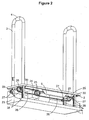
- a modular step elevator of a Staircase Elevator Device suitable for ascending/descending any given number of steps of a staircase comprises a base 1 firmly arranged in a non-destructive way on the horizontal surface of the staircase step the modular step elevator is associated with and shaped according to the shape of the horizontal surface of the staircase step and a movable platform 2 having the same shape as the base 1 and beeing able to be moved up or down between the base 1 of the modular step elevator and the level of the lower position of the movable platform of the modular step elevator associated with the next higher staircase step by means of an electric, pneumatic or hydraulic actuator.
- the base can be metallic and/or wooden and has the shape of the horizontal surface of the staircase step, to which it is assigned.
- the movable platform 2 shown in Figure 1 has two handholds 3 beeing arranged at opposite sides of the movable platform 2 verticaly to the riser and to the movable platform 2, whereby the actuator of the is modular step elevator is controllable by a user by means of control means 4 provided on at least one handhold 3 of the movable platform 2.
- the movable platform 2 is electrically driven by means of an electric motor 6 and preferably trapezoidal screws 5 fixed vertically near the corners of the base 1 and passing through holes of the movable platform 2.
- the motor is a 12V motor with a housing vertically fixed on top of the the movable platform 2.
- At least one suitable, recharchable battery for providing the electric energy for the motor 6 of the modular step elevators of the Staircase Elevator Device is provided (not shown).
- the motor 6 drives a first motor pulley 7 which is connected by means of a first timing belt 8 with a central reduction pulley 9 which is arranged on a shaft 10 on which a second and a third pulley 11, 12 serving as distribution pulleys are arranged.
- the first, second and third pulley 9, 11, 12 are rotating with the shaft 10.
- the second and third pulley 11,12 transfer momentum by means of second and third belts 13, 14 to peripheral pulleys 15, 16, 17, 18, whereby each peripheral pulley 15,16,17,18 drives a nut 19 on each trapezoidal screw 5, screwing or unscrewing them along the trapezoidal screws 5, thus converting the rotational movement into an up or down movement and driving the inner rings of the ball bearings 20 to ascent or descent, whereby the outer rings of the ball bearings 20 are fixed to the movable platform 2.
- the inner rings of the bearings 20 are revolved by the trapezoidal nuts 19.
- A can be taken by Figure 1 , the trapezoidal screws 5 are partialy guided (the upper part thereof depending on the movement of the movable platform 2) through the handholds 3, which are configured as hollow bodies. In order to show this feature a part of the left part of the left handhold 3 is not shown so that the upper part of the screw 5 guided through the handhold can bee seen.
- the modular step elevator comprises a height adjustment screw 21 which is preadjusted to stop the movement of the movable platform 2 at the level of the lower position of the movable platform of the modular step elevator associated with the next higher staircase step.
- FIG. 1 shows the bases 1 of the modular step elevators associated with one staircase between two floors are firmly connected to each other by means of at least one stable profile 22 in a stable, united and all-integrated Device, whereby the at least one profile 22 is running along and parallel to the inclination of the staircase from the lower floor to the higher floor and can serve also as a guide channel for the cables needed for the operation of the actuators of the movable platforms 2.
- side vertical plates 23 can be provided which are fixed at one or both sides of the base 1, on which the at least one profile 22 is affixed.
- the Staircase Elevator Device also comprises limit-switches and relays used to activate the motors of the modular step elevators in order to be controllable by the user for up or down movement either separately for each modular step elevator or sequentially for all modular step elevators on the staircase steps.
- the embodiment shown in Figure 2 differs from the embodiment shown in Figure 1 in that the the movable platform 2 is electrically driven by means of an electric motor 6 and toothed racks 28 fixed vertically near the corners of the base 1, passing through proper holes of the movable platform 2 and partialy guided (the upper part thereof depending on the movement of the movable platform 2) through the handholds 3, which are configured as hollow bodies.
- the motor 6 is coupled to a gear box 24 for speed reduction, whereby the momentum is transferred from the gear box 24 by sprockets 25 and chains 26 to peripheral gears 27 arranged on axles 29 according to the principle of a chain drive, which are movable up or down along the racks 28, thus carrying upwards or downwards the movable platform 2, at which the ends of the axles 29 are rotatably fixed.
- the peripheral gears 27, engaged to the racks 28 provide synchronous and parallel movement of the movable platform 2 by elevating it at the preadjusted height by a height adjustment screw shown in Figure 1 at the level of the lower position of the movable platform of the modular step elevator associated with the next higher staircase step.
- roller means 30 assigned to each rack 28 arranged on axles can be provided to avoid friction between the racks 28 and to ensure a smooth movement of the movable platform 2.
- the embodiment shown in Figure 3 differs from the embodiment shown in figure 1 in that the the movable platform 2 is pneumatically or hydraulically driven by means of pneumatic or hydraulic cylinders 31 and toothed racks 32, fixed vertically near the corners of the base 1, passing through proper holes of the movable platform 2 and partialy guided (the upper part thereof depending on the movement of the movable platform 2) through the handholds 3, which are configured as hollow bodies.
- the cylinders 31 are fixed vertically at both sides on the top of the movable platform 2 and have piston rods 33 fixed on the base 1, initiating the up or down movement of the movable platform 2.
- the compressed air or oil moves the pistons rods 33 depending on the operation mode up or down, thus changing the distance between the base 1 and the movable platform 2.
- the compressed air or oil of an air compressor or oil pump moves through a tubing and corresponding air or oil valves the piston rods 33 vertically and in synchronous mode, which are movable the platform 2 at a height preadjusted by a height adjustment screw (not shown).
- the movement of the movable platform 2 can be supported by peripheral gears 34, engaged to the racks 32, providing synchronous up or down movement of the movable platform 2.
- a chain 37, sprockets 35 and axles 36 are provided, transferring synchronous rotation to peripheral gears 34 engaged to the racks 32, whereby for each side of the modular step elevator an axle 36 is provided, on which a sprocket 35 and gears 34 assigned to the racks 32 are firmly arranged.
- the sprockets 35 of both sides are connected to reach other by means of a revolving chain 37 for synchronization.
- roller means 30 assigned to each rack 32 arranged on axles can be provided to avoid friction between the racks 32 and to ensure a smooth movement of the movable platform 2.
- the Staircase Elevator Device also comprises flow controls for regulating the upwards or downwards speed of the movable platform 2, either separately for each movable platform 2 or sequentially for all movable platforms 2 on the staircase steps.
- the bases 1 of the modular step elevators associated with one staircase between two associated with one staircase between two floors are firmly connected to each other by means of at least one stable profilen in a stable, united and all-integrated Device, whereby the profile Is running along and parallel to the inclination of the staircase from the lower floor to the higher floor and can serve as a guide channel for the cables and the tubing needed for the operation of the pneumatic or hydraulic cylinders of the movable platforms 2.
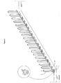
- FIG. 4 shows a Staircase Elevator Device according to the invention comprising 18 modular step elevators installed on a staircase having 18 steps.
- the bases of the modular step elevators associated with the staircase are firmly connected to each other by means of a stable profile 22 running along and parallel to the inclination of the staircase from the lower floor to the higher floor.
- the operation of the Staircase Elevator Device for ascending is as follows:
- the user holds the handholds of the lowest 'first' modular staircase elevator and stands on its movable platform ( figure 5a ).
- By pressing an "up" button on the handhold or by suitably operating a control stick the 'first' platform ascents to the level of the next, 'second' movable platform of the modular staircase elevator associated with the next higher staircase step, which is in the lower position ( Figure 5b ).
- the two movable platforms are at this stage at the same level and the user holds the handholds 3 of the second movable platform and moves from the 'first' on the 'second' movable platform and stands on it ( Figure 5b ).
- the 'second' movable platform By pressing the "up" push button or by suitably operating a control stick on the handhold the 'second' movable platform he ascents to the level of the next 'third' movable platform ( Figure 5c, Figure 5d ) and so on and so forth until the 17 th step ( Figure 5e ) and the higher floor is reached ( Figure 5f ).
- the same procedure as for ascenting applies for descending the stairs of the staircase by pressing the "down" button or by suitably operating a control stick of the respective handholds 3.
Landscapes
- Engineering & Computer Science (AREA)
- Transportation (AREA)
- Automation & Control Theory (AREA)
- Structural Engineering (AREA)
- Types And Forms Of Lifts (AREA)
- Handcart (AREA)
Claims (10)
- Treppenaufzugsvorrichtung zum Hinauf/Hinabsteigen einer beliebigen Anzahl von Stufen einer Treppe, umfassend eine der Anzahl der Stufen der Treppe entsprechende Anzahl von modularen Stufenaufzügen, wobei jeder einzelne modulare Stufenaufzug einer Treppenstufe zugeordnet ist, wobei jeder modulare Stufenaufzug eine Basis (1), die auf der horizontalen Oberfläche der Treppenstufe, der der modulare Stufenaufzug zugeordnet ist, fest angeordnet ist und entsprechend der Form der horizontalen Oberfläche der Treppenstufe geformt ist, und eine bewegliche Plattform (2) umfasst, die die gleiche Form wie die Basis (1) aufweist und durch einen elektrischen, pneumatischen oder hydraulischen Aktuator zwischen der Basis (1) des modularen Stufenaufzuges und dem Niveau der unteren Position der beweglichen Plattform (2) des modularen Stufenaufzuges, der der nächsthöheren Stufe zugeordnet ist, hinauf und hinab bewegbar ist, wobei die bewegliche Plattform (2) mindestens einem Handlauf (3) aufweist, der an einer Seite der beweglichen Plattform (2) im Wesentlichen senkrecht zu der Treppenstufe und zu der beweglichen Plattform (2) angeordnet ist, wobei der elektrische, pneumatische oder hydraulische Aktuator von einem Benutzer durch an mindestens einem Handlauf (3) der beweglichen Plattform (2) bereitgestellte Steuermittel (4) steuerbar ist, wobei die erste Treppenstufe ein Bereich der Bodenebene des unteren Stockwerks und die letzte Treppenstufe ein Bereich der Bodenebene des höheren Stockwerks ist, wobei der letzten Treppenstufe kein modularer Stufenaufzug zugeordnet ist, wobei die bewegliche Plattform (2) des modularen Stufenaufzuges, der der vorletzten Treppenstufe zugeordnet ist, zwischen der Basis (1) und der Bodenebene des höheren Stockwerkes hinauf oder hinab bewegbar ist, dadurch gekennzeichnet, dass jeder einzelne einer Treppenstufe zugeordnete modulare Stufenaufzug zerstörungsfrei mit der Treppenstufe verbunden ist, dass die modularen Stufenaufzüge mittels eines oder zwei länglichen Metallprofilen fest zu einer stabilen, einheitlichen und integrierten Treppenaufzugsvorrichtung kombiniert sind, und dass die Basen (1) der modularen Stufenaufzüge, die einer Treppe zwischen zwei Stockwerken zugeordnet sind, durch mindestens ein stabiles Profil (22), das entlang und parallel zu der Neigung der Treppe von dem unteren Stockwerk zu dem oberen Stockwerk verläuft und auch als Führungskanal für die Kabel und/oder Leitungen, die zum Betrieb der Aktuatoren der beweglichen Plattformen (2) benötigt werden, verwendet wird, fest miteinander verbunden sind.
- Treppenaufzugsvorrichtung nach Patentanspruch 1, dadurch gekennzeichnet, dass die bewegliche Plattform (2) durch einen Elektromotor (6) und Trapezgewinde (5), die senkrecht in der Nähe der Ecken der Basis (1) angebracht und durch Löcher in der beweglichen Plattform (2) geführt sind, elektrisch angetrieben wird, wobei der Motor (6) eine erste Motorriemenscheibe (7) antreibt, welche mittels eines ersten Zahnriemens (8) mit einer mittig angeordneten, auf einer Welle (10) gelagerten Untersetzungsscheibe (9) verbunden ist, wobei auf der Welle eine zweite und eine dritte Riemenscheibe (11, 12) angeordnet sind, wobei sich die erste, zweite und dritte Riemenscheibe (9), (11), (12) mit der Welle (10) drehen, und die zweite und dritte Riemenscheibe (11, 12) das Drehmoment über einen zweiten und dritten Riemen (13, 14) zu äußeren Riemenscheiben (15, 16, 17, 18) übertragen, wobei jede äußere Riemenscheibe (15, 16, 17, 18) eine Mutter (19) auf jedem Trapezgewinde (5) antreibt und diese entlang der Trapezgewinde (5) auf- und abschraubt, wodurch die Rotationsbewegung durch Kugellager (20) in eine Aufoder Ab-Bewegung umgewandelt wird und die inneren Ringe von Kugellagern (20) so angetrieben werden, dass sie sich hinauf und hinabbewegen, wobei die äußeren Ringe der Kugellager (20) fest mit der beweglichen Plattform (2) verbunden sind und die inneren Ringe der Kugellager (20) durch die Trapezmuttern (19) gedreht werden.
- Treppenaufzugsvorrichtung nach Patentanspruch 1, dadurch gekennzeichnet, dass die bewegliche Plattform (2) durch einen Elektromotor (6) und Zahnstangen (28), die senkrecht in der Nähe der Ecken der Basis (1) angeordnet sind und durch passende Löcher in der beweglichen Plattform (2) geführt sind, elektrisch angetrieben wird, wobei der Motor (6) mit einem Getriebe (24) zur Geschwindigkeitsreduktion verbunden ist und das Drehmoment von dem Getriebe (24) über Zahnräder (25) und Ketten (26) weiter zu äußeren Zahnrädern (27) übertragen wird, welche auf Achsen (29) gelagert sind, die sich entlang der Zahnstangen (28) auf oder ab bewegen können, wodurch die bewegliche Plattform (2), an der die Enden der Achsen (29) befestigt sind, hinauf und hinab bewegt wird, wobei die äußeren Zahnräder (27), die mit den Zahnstangen (28) in Eingriff stehen, für eine synchrone und parallele Bewegung der beweglichen Plattform (2) sorgen.
- Treppenaufzugsvorrichtung nach Patentanspruch 1, dadurch gekennzeichnet, dass die bewegliche Plattform (2) durch pneumatische oder hydraulische Zylinder (31) und Zahnstangen (32), die senkrecht in der Nähe der Ecken der Basis (1) platziert sind und durch passende Löcher in der beweglichen Plattform (2) geführt sind, pneumatisch oder hydraulisch angetrieben wird, wobei die Zylinder (31) senkrecht an beiden Seiten an der Oberseite der beweglichen Plattform (2) befestigt sind und Kolbenstangen (33) aufweisen, die an der Basis (1) befestigt sind und die Auf- oder Ab-Bewegung der beweglichen Plattform (2) veranlassen, wobei Pressluft oder Öl die Kolbenstangen (33) senkrecht und synchron auf oder ab bewegt, wodurch der Abstand zwischen der Basis (1) und der beweglichen Plattform (2) verändert wird.
- Treppenaufzugsvorrichtung nach Patentanspruch 4, dadurch gekennzeichnet, dass die Bewegung der beweglichen Plattform (2) durch äußere Zahnräder (34), die mit Zahnstangen (32) in Eingriff stehen, unterstützt wird, so dass eine synchrone Auf- oder Ab-Bewegung der beweglichen Plattform (2) ermöglicht wird, wobei eine Kette (37), Achsen (36) und Kettenräder (35) vorgesehen sind, welche die synchrone Rotation zu den äußeren Zahnrädern (34) übertragen, wobei für jede Seite des modularen Stufenaufzuges eine Achse (36) vorgesehen ist, mit der ein Kettenrad (35) und Zahnräder (34), die den Zahnstangen (32) zugeordnet sind, fest verbunden sind, wobei die Kettenräder (35) an jeder Seite miteinander mittels eines Kettentriebs (37) zur Synchronisierung verbunden sind.
- Treppenaufzugsvorrichtung nach Patentanspruch 2, 3, 4 oder 5 dadurch gekennzeichnet, dass jeder modulare Stufenaufzug eine Höheneinstellungsschraube (21) umfasst, die voreingestellt ist, um die Bewegung der beweglichen Plattform (2) auf dem Niveau der unteren Position der beweglichen Plattform des modularen Stufenaufzugs, das der nächsthöheren Stufe (2) zugeordnet ist, zu stoppen.
- Treppenaufzugsvorrichtung nach Patentanspruch 1, 2, 3, 4, 5 oder 6, dadurch gekennzeichnet, dass die Steuermittel (4) entweder Steuertasten oder ein Steuerknüppel sind.
- Verfahren zum Betreiben einer Treppenaufzugsvorrichtung nach einem der vorangehenden Patentansprüche, dadurch gekennzeichnet, dass ein Benutzer die Handläufe (3) des untersten "ersten" modularen Stufenaufzugs hält und auf seiner beweglichen Plattform steht, wobei durch Pressen eines "Aufwärts"-Knopfs an dem Handlauf oder mittels einer geeigneten Bedienung eines Steuerknüppels die "erste" bewegliche Plattform (2) auf das Niveau der "zweiten" beweglichen Plattform (2) des modularen Stufenaufzugs, die der nächsthöheren Treppenstufe zugeordnet ist und sich in der unteren Position befindet, steigt, so dass sich beide beweglichen Plattformen (2) auf dem gleichen Niveau befinden wobei, in einem nächsten Schritt der Benutzer die Handläufe der "zweiten" beweglichen Plattform hält ,sich von der "ersten" auf die "zweite" bewegliche Plattform (2) bewegt und auf der "zweiten" beweglichen Plattform steht, wobei er durch Pressen eines "Aufwärts" - Knopfs oder mittels einer geeigneten Bedienung eines Steuerknüppels auf dem Handlauf (3) der "zweiten" beweglichen Plattform (2) auf das Niveau der "dritten" beweglichen Plattform (2) hinaufsteigt und so weiter und so fort bis das obere Stockwerk erreicht ist, wobei für das Hinabsteigen der Stufen der Treppe die gleiche Prozedur wie für das Hinaufsteigen durch Pressen des "Abwärts"-Knopfs oder durch geeignete Bedienung eines Steuerknüppels auf dem jeweiligen Handlauf (3) angewandt wird.
- Verfahren zum Betreiben einer Treppenaufzugsvorrichtung nach Patentanspruch 8, dadurch gekennzeichnet, dass die Handläufe (3) jeder beweglichen Plattform (2) einen berührungsempfindlichen Sensor aufweisen, wobei die Bewegung einer beweglichen Plattform (2) beginnt, wenn der berührungsempfindliche Sensor für eine vorgegebene Zeit berührt wird.
- Verfahren zum Betreiben einer Treppenaufzugsvorrichtung nach einem der vorangehenden Patentansprüchen 1 bis 7, dadurch gekennzeichnet, dass das Hinauf- und Hinabsteigen automatisiert abläuft, wobei die beweglichen Plattformen (2) nacheinander je nach Betriebsmodus in vordefinierten, einstellbaren Zeitintervallen hinauf oder hinab bewegt werden, wobei der Benutzer einen Alarmknopf, der an den Handläufen (3) angeordnet ist, betätigen kann, der die Bewegung stoppt, falls die Zeitintervalle zu kurz sind oder Probleme auftreten.
Priority Applications (3)
| Application Number | Priority Date | Filing Date | Title |
|---|---|---|---|
| EP14156811.3A EP2913290B1 (de) | 2014-02-26 | 2014-02-26 | Treppenaufzugsvorrichtung |
| PL14156811.3T PL2913290T3 (pl) | 2014-02-26 | 2014-02-26 | Schodowe urządzenie dźwigowe |
| CY20161100691T CY1117789T1 (el) | 2014-02-26 | 2016-07-15 | Μηχανισμος αναβατοριου κλιμακοστασιου |
Applications Claiming Priority (1)
| Application Number | Priority Date | Filing Date | Title |
|---|---|---|---|
| EP14156811.3A EP2913290B1 (de) | 2014-02-26 | 2014-02-26 | Treppenaufzugsvorrichtung |
Publications (2)
| Publication Number | Publication Date |
|---|---|
| EP2913290A1 EP2913290A1 (de) | 2015-09-02 |
| EP2913290B1 true EP2913290B1 (de) | 2016-04-27 |
Family
ID=50159135
Family Applications (1)
| Application Number | Title | Priority Date | Filing Date |
|---|---|---|---|
| EP14156811.3A Not-in-force EP2913290B1 (de) | 2014-02-26 | 2014-02-26 | Treppenaufzugsvorrichtung |
Country Status (3)
| Country | Link |
|---|---|
| EP (1) | EP2913290B1 (de) |
| CY (1) | CY1117789T1 (de) |
| PL (1) | PL2913290T3 (de) |
Families Citing this family (2)
| Publication number | Priority date | Publication date | Assignee | Title |
|---|---|---|---|---|
| IT201600071622A1 (it) | 2016-07-08 | 2018-01-08 | Giovanni Teglia | Dispositivo di ausilio per salire/scendere scale |
| CN117088219A (zh) * | 2023-09-06 | 2023-11-21 | 任丘市杰东机械配件有限公司 | 移步举升式步行机 |
Family Cites Families (1)
| Publication number | Priority date | Publication date | Assignee | Title |
|---|---|---|---|---|
| NL2004022C2 (nl) * | 2009-12-24 | 2011-09-09 | Univ Twente | Tredeliftsamenstel, tredelift en werkwijze. |
-
2014
- 2014-02-26 PL PL14156811.3T patent/PL2913290T3/pl unknown
- 2014-02-26 EP EP14156811.3A patent/EP2913290B1/de not_active Not-in-force
-
2016
- 2016-07-15 CY CY20161100691T patent/CY1117789T1/el unknown
Also Published As
| Publication number | Publication date |
|---|---|
| CY1117789T1 (el) | 2017-05-17 |
| EP2913290A1 (de) | 2015-09-02 |
| PL2913290T3 (pl) | 2016-11-30 |
Similar Documents
| Publication | Publication Date | Title |
|---|---|---|
| US8418787B2 (en) | Stair climbing apparatus | |
| JP7069146B2 (ja) | 高さの差を克服するための移動補助デバイス | |
| US7185741B1 (en) | System with moving zero step for stairs | |
| EP2913290B1 (de) | Treppenaufzugsvorrichtung | |
| US8104600B2 (en) | Escalator | |
| CN109484950A (zh) | 无障碍升降装置及通用楼梯 | |
| CN209291751U (zh) | 无障碍升降装置及通用楼梯 | |
| CN111362102B (zh) | 带电梯的别墅楼梯及其工作方法 | |
| CN111689342B (zh) | 一种平步楼梯装置 | |
| CN104477740A (zh) | 单人货物升降装置 | |
| CN106809713A (zh) | 轨道式楼梯上下楼器 | |
| Gaikwad et al. | Modeling and analysis of a stair case lift for material handling system | |
| JP2009102172A (ja) | 多目的自動昇降ステップシステム | |
| CN107758477A (zh) | 分层式双索传动上下楼助力装置 | |
| CN213894835U (zh) | 一种行动不便人员使用的升降机 | |
| JP2984237B2 (ja) | 階段用昇降装置 | |
| KR102499849B1 (ko) | 무대 리프트 겸용 가변식 계단장치 | |
| RU2462408C1 (ru) | Лестничный подъемник | |
| CN111039129A (zh) | 一种用于既有民居楼梯的轮椅升降辅助装置 | |
| RU2563076C1 (ru) | Подъемное устройство (варианты) | |
| CN217376926U (zh) | 一种自动爬楼装置 | |
| CN213894836U (zh) | 一种轨道式爬楼机 | |
| CN204737547U (zh) | 楼间升降系统 | |
| JP2500370B2 (ja) | 身障者用階段昇降機 | |
| JPH0530063U (ja) | 昇降装置 |
Legal Events
| Date | Code | Title | Description |
|---|---|---|---|
| PUAI | Public reference made under article 153(3) epc to a published international application that has entered the european phase |
Free format text: ORIGINAL CODE: 0009012 |
|
| 17P | Request for examination filed |
Effective date: 20140710 |
|
| AK | Designated contracting states |
Kind code of ref document: A1 Designated state(s): AL AT BE BG CH CY CZ DE DK EE ES FI FR GB GR HR HU IE IS IT LI LT LU LV MC MK MT NL NO PL PT RO RS SE SI SK SM TR |
|
| AX | Request for extension of the european patent |
Extension state: BA ME |
|
| GRAP | Despatch of communication of intention to grant a patent |
Free format text: ORIGINAL CODE: EPIDOSNIGR1 |
|
| INTG | Intention to grant announced |
Effective date: 20151023 |
|
| GRAS | Grant fee paid |
Free format text: ORIGINAL CODE: EPIDOSNIGR3 |
|
| GRAA | (expected) grant |
Free format text: ORIGINAL CODE: 0009210 |
|
| AK | Designated contracting states |
Kind code of ref document: B1 Designated state(s): AL AT BE BG CH CY CZ DE DK EE ES FI FR GB GR HR HU IE IS IT LI LT LU LV MC MK MT NL NO PL PT RO RS SE SI SK SM TR |
|
| REG | Reference to a national code |
Ref country code: GB Ref legal event code: FG4D |
|
| REG | Reference to a national code |
Ref country code: CH Ref legal event code: EP |
|
| REG | Reference to a national code |
Ref country code: AT Ref legal event code: REF Ref document number: 794563 Country of ref document: AT Kind code of ref document: T Effective date: 20160515 |
|
| REG | Reference to a national code |
Ref country code: IE Ref legal event code: FG4D |
|
| REG | Reference to a national code |
Ref country code: DE Ref legal event code: R096 Ref document number: 602014001617 Country of ref document: DE |
|
| REG | Reference to a national code |
Ref country code: CH Ref legal event code: NV Representative=s name: ABREMA AGENCE BREVET ET MARQUES, GANGUILLET, CH |
|
| REG | Reference to a national code |
Ref country code: NL Ref legal event code: FP |
|
| REG | Reference to a national code |
Ref country code: SE Ref legal event code: TRGR |
|
| REG | Reference to a national code |
Ref country code: LT Ref legal event code: MG4D |
|
| PG25 | Lapsed in a contracting state [announced via postgrant information from national office to epo] |
Ref country code: LT Free format text: LAPSE BECAUSE OF FAILURE TO SUBMIT A TRANSLATION OF THE DESCRIPTION OR TO PAY THE FEE WITHIN THE PRESCRIBED TIME-LIMIT Effective date: 20160427 Ref country code: NO Free format text: LAPSE BECAUSE OF FAILURE TO SUBMIT A TRANSLATION OF THE DESCRIPTION OR TO PAY THE FEE WITHIN THE PRESCRIBED TIME-LIMIT Effective date: 20160727 Ref country code: FI Free format text: LAPSE BECAUSE OF FAILURE TO SUBMIT A TRANSLATION OF THE DESCRIPTION OR TO PAY THE FEE WITHIN THE PRESCRIBED TIME-LIMIT Effective date: 20160427 |
|
| PG25 | Lapsed in a contracting state [announced via postgrant information from national office to epo] |
Ref country code: LV Free format text: LAPSE BECAUSE OF FAILURE TO SUBMIT A TRANSLATION OF THE DESCRIPTION OR TO PAY THE FEE WITHIN THE PRESCRIBED TIME-LIMIT Effective date: 20160427 Ref country code: RS Free format text: LAPSE BECAUSE OF FAILURE TO SUBMIT A TRANSLATION OF THE DESCRIPTION OR TO PAY THE FEE WITHIN THE PRESCRIBED TIME-LIMIT Effective date: 20160427 Ref country code: HR Free format text: LAPSE BECAUSE OF FAILURE TO SUBMIT A TRANSLATION OF THE DESCRIPTION OR TO PAY THE FEE WITHIN THE PRESCRIBED TIME-LIMIT Effective date: 20160427 Ref country code: PT Free format text: LAPSE BECAUSE OF FAILURE TO SUBMIT A TRANSLATION OF THE DESCRIPTION OR TO PAY THE FEE WITHIN THE PRESCRIBED TIME-LIMIT Effective date: 20160829 Ref country code: ES Free format text: LAPSE BECAUSE OF FAILURE TO SUBMIT A TRANSLATION OF THE DESCRIPTION OR TO PAY THE FEE WITHIN THE PRESCRIBED TIME-LIMIT Effective date: 20160427 |
|
| PG25 | Lapsed in a contracting state [announced via postgrant information from national office to epo] |
Ref country code: BE Free format text: LAPSE BECAUSE OF FAILURE TO SUBMIT A TRANSLATION OF THE DESCRIPTION OR TO PAY THE FEE WITHIN THE PRESCRIBED TIME-LIMIT Effective date: 20160427 |
|
| REG | Reference to a national code |
Ref country code: DE Ref legal event code: R097 Ref document number: 602014001617 Country of ref document: DE |
|
| PG25 | Lapsed in a contracting state [announced via postgrant information from national office to epo] |
Ref country code: EE Free format text: LAPSE BECAUSE OF FAILURE TO SUBMIT A TRANSLATION OF THE DESCRIPTION OR TO PAY THE FEE WITHIN THE PRESCRIBED TIME-LIMIT Effective date: 20160427 Ref country code: SK Free format text: LAPSE BECAUSE OF FAILURE TO SUBMIT A TRANSLATION OF THE DESCRIPTION OR TO PAY THE FEE WITHIN THE PRESCRIBED TIME-LIMIT Effective date: 20160427 Ref country code: CZ Free format text: LAPSE BECAUSE OF FAILURE TO SUBMIT A TRANSLATION OF THE DESCRIPTION OR TO PAY THE FEE WITHIN THE PRESCRIBED TIME-LIMIT Effective date: 20160427 Ref country code: DK Free format text: LAPSE BECAUSE OF FAILURE TO SUBMIT A TRANSLATION OF THE DESCRIPTION OR TO PAY THE FEE WITHIN THE PRESCRIBED TIME-LIMIT Effective date: 20160427 Ref country code: RO Free format text: LAPSE BECAUSE OF FAILURE TO SUBMIT A TRANSLATION OF THE DESCRIPTION OR TO PAY THE FEE WITHIN THE PRESCRIBED TIME-LIMIT Effective date: 20160427 |
|
| REG | Reference to a national code |
Ref country code: GR Ref legal event code: EP Ref document number: 20160401625 Country of ref document: GR Effective date: 20161020 |
|
| PG25 | Lapsed in a contracting state [announced via postgrant information from national office to epo] |
Ref country code: SM Free format text: LAPSE BECAUSE OF FAILURE TO SUBMIT A TRANSLATION OF THE DESCRIPTION OR TO PAY THE FEE WITHIN THE PRESCRIBED TIME-LIMIT Effective date: 20160427 |
|
| PLBE | No opposition filed within time limit |
Free format text: ORIGINAL CODE: 0009261 |
|
| STAA | Information on the status of an ep patent application or granted ep patent |
Free format text: STATUS: NO OPPOSITION FILED WITHIN TIME LIMIT |
|
| 26N | No opposition filed |
Effective date: 20170130 |
|
| PG25 | Lapsed in a contracting state [announced via postgrant information from national office to epo] |
Ref country code: SI Free format text: LAPSE BECAUSE OF FAILURE TO SUBMIT A TRANSLATION OF THE DESCRIPTION OR TO PAY THE FEE WITHIN THE PRESCRIBED TIME-LIMIT Effective date: 20160427 |
|
| PGFP | Annual fee paid to national office [announced via postgrant information from national office to epo] |
Ref country code: IT Payment date: 20170228 Year of fee payment: 4 |
|
| PG25 | Lapsed in a contracting state [announced via postgrant information from national office to epo] |
Ref country code: MC Free format text: LAPSE BECAUSE OF FAILURE TO SUBMIT A TRANSLATION OF THE DESCRIPTION OR TO PAY THE FEE WITHIN THE PRESCRIBED TIME-LIMIT Effective date: 20160427 |
|
| REG | Reference to a national code |
Ref country code: CH Ref legal event code: PL |
|
| REG | Reference to a national code |
Ref country code: SE Ref legal event code: EUG |
|
| REG | Reference to a national code |
Ref country code: NL Ref legal event code: MM Effective date: 20170301 |
|
| PG25 | Lapsed in a contracting state [announced via postgrant information from national office to epo] |
Ref country code: CH Free format text: LAPSE BECAUSE OF NON-PAYMENT OF DUE FEES Effective date: 20170228 Ref country code: LI Free format text: LAPSE BECAUSE OF NON-PAYMENT OF DUE FEES Effective date: 20170228 Ref country code: CY Free format text: LAPSE BECAUSE OF NON-PAYMENT OF DUE FEES Effective date: 20170226 |
|
| REG | Reference to a national code |
Ref country code: IE Ref legal event code: MM4A |
|
| PG25 | Lapsed in a contracting state [announced via postgrant information from national office to epo] |
Ref country code: SE Free format text: LAPSE BECAUSE OF NON-PAYMENT OF DUE FEES Effective date: 20170227 Ref country code: NL Free format text: LAPSE BECAUSE OF NON-PAYMENT OF DUE FEES Effective date: 20170301 |
|
| REG | Reference to a national code |
Ref country code: FR Ref legal event code: ST Effective date: 20171031 |
|
| PG25 | Lapsed in a contracting state [announced via postgrant information from national office to epo] |
Ref country code: LU Free format text: LAPSE BECAUSE OF NON-PAYMENT OF DUE FEES Effective date: 20170226 |
|
| PG25 | Lapsed in a contracting state [announced via postgrant information from national office to epo] |
Ref country code: FR Free format text: LAPSE BECAUSE OF NON-PAYMENT OF DUE FEES Effective date: 20170228 |
|
| PG25 | Lapsed in a contracting state [announced via postgrant information from national office to epo] |
Ref country code: IE Free format text: LAPSE BECAUSE OF NON-PAYMENT OF DUE FEES Effective date: 20170226 |
|
| PG25 | Lapsed in a contracting state [announced via postgrant information from national office to epo] |
Ref country code: PL Free format text: LAPSE BECAUSE OF NON-PAYMENT OF DUE FEES Effective date: 20170226 |
|
| REG | Reference to a national code |
Ref country code: AT Ref legal event code: UEP Ref document number: 794563 Country of ref document: AT Kind code of ref document: T Effective date: 20160427 |
|
| PG25 | Lapsed in a contracting state [announced via postgrant information from national office to epo] |
Ref country code: MT Free format text: LAPSE BECAUSE OF NON-PAYMENT OF DUE FEES Effective date: 20170226 |
|
| GBPC | Gb: european patent ceased through non-payment of renewal fee |
Effective date: 20180226 |
|
| PG25 | Lapsed in a contracting state [announced via postgrant information from national office to epo] |
Ref country code: AL Free format text: LAPSE BECAUSE OF FAILURE TO SUBMIT A TRANSLATION OF THE DESCRIPTION OR TO PAY THE FEE WITHIN THE PRESCRIBED TIME-LIMIT Effective date: 20160427 |
|
| PG25 | Lapsed in a contracting state [announced via postgrant information from national office to epo] |
Ref country code: GB Free format text: LAPSE BECAUSE OF NON-PAYMENT OF DUE FEES Effective date: 20180226 Ref country code: IT Free format text: LAPSE BECAUSE OF NON-PAYMENT OF DUE FEES Effective date: 20180226 |
|
| PG25 | Lapsed in a contracting state [announced via postgrant information from national office to epo] |
Ref country code: HU Free format text: LAPSE BECAUSE OF FAILURE TO SUBMIT A TRANSLATION OF THE DESCRIPTION OR TO PAY THE FEE WITHIN THE PRESCRIBED TIME-LIMIT; INVALID AB INITIO Effective date: 20140226 |
|
| PG25 | Lapsed in a contracting state [announced via postgrant information from national office to epo] |
Ref country code: BG Free format text: LAPSE BECAUSE OF FAILURE TO SUBMIT A TRANSLATION OF THE DESCRIPTION OR TO PAY THE FEE WITHIN THE PRESCRIBED TIME-LIMIT Effective date: 20160427 |
|
| PG25 | Lapsed in a contracting state [announced via postgrant information from national office to epo] |
Ref country code: MK Free format text: LAPSE BECAUSE OF FAILURE TO SUBMIT A TRANSLATION OF THE DESCRIPTION OR TO PAY THE FEE WITHIN THE PRESCRIBED TIME-LIMIT Effective date: 20160427 |
|
| PG25 | Lapsed in a contracting state [announced via postgrant information from national office to epo] |
Ref country code: TR Free format text: LAPSE BECAUSE OF FAILURE TO SUBMIT A TRANSLATION OF THE DESCRIPTION OR TO PAY THE FEE WITHIN THE PRESCRIBED TIME-LIMIT Effective date: 20160427 |
|
| REG | Reference to a national code |
Ref country code: AT Ref legal event code: MM01 Ref document number: 794563 Country of ref document: AT Kind code of ref document: T Effective date: 20190226 |
|
| PG25 | Lapsed in a contracting state [announced via postgrant information from national office to epo] |
Ref country code: AT Free format text: LAPSE BECAUSE OF NON-PAYMENT OF DUE FEES Effective date: 20190226 |
|
| PG25 | Lapsed in a contracting state [announced via postgrant information from national office to epo] |
Ref country code: IS Free format text: LAPSE BECAUSE OF FAILURE TO SUBMIT A TRANSLATION OF THE DESCRIPTION OR TO PAY THE FEE WITHIN THE PRESCRIBED TIME-LIMIT Effective date: 20160827 |
|
| PGFP | Annual fee paid to national office [announced via postgrant information from national office to epo] |
Ref country code: DE Payment date: 20211123 Year of fee payment: 9 |
|
| REG | Reference to a national code |
Ref country code: DE Ref legal event code: R082 Ref document number: 602014001617 Country of ref document: DE Representative=s name: KARAKATSANIS, GEORGIOS, DR., DE |
|
| PGFP | Annual fee paid to national office [announced via postgrant information from national office to epo] |
Ref country code: GR Payment date: 20230202 Year of fee payment: 10 |
|
| REG | Reference to a national code |
Ref country code: DE Ref legal event code: R119 Ref document number: 602014001617 Country of ref document: DE |
|
| PG25 | Lapsed in a contracting state [announced via postgrant information from national office to epo] |
Ref country code: DE Free format text: LAPSE BECAUSE OF NON-PAYMENT OF DUE FEES Effective date: 20230901 |
|
| PG25 | Lapsed in a contracting state [announced via postgrant information from national office to epo] |
Ref country code: GR Free format text: LAPSE BECAUSE OF NON-PAYMENT OF DUE FEES Effective date: 20240904 |
|
| PG25 | Lapsed in a contracting state [announced via postgrant information from national office to epo] |
Ref country code: GR Free format text: LAPSE BECAUSE OF NON-PAYMENT OF DUE FEES Effective date: 20240904 |