EP2913290B1 - Staircase elevator device - Google Patents
Staircase elevator device Download PDFInfo
- Publication number
- EP2913290B1 EP2913290B1 EP14156811.3A EP14156811A EP2913290B1 EP 2913290 B1 EP2913290 B1 EP 2913290B1 EP 14156811 A EP14156811 A EP 14156811A EP 2913290 B1 EP2913290 B1 EP 2913290B1
- Authority
- EP
- European Patent Office
- Prior art keywords
- movable platform
- staircase
- elevator
- modular
- movable
- Prior art date
- Legal status (The legal status is an assumption and is not a legal conclusion. Google has not performed a legal analysis and makes no representation as to the accuracy of the status listed.)
- Active
Links
- 230000001174 ascending effect Effects 0.000 claims description 14
- 230000002093 peripheral effect Effects 0.000 claims description 12
- 238000000034 method Methods 0.000 claims description 8
- 230000001360 synchronised effect Effects 0.000 claims description 8
- 230000009467 reduction Effects 0.000 claims description 5
- 230000001066 destructive effect Effects 0.000 claims description 3
- 230000000977 initiatory effect Effects 0.000 claims description 2
- 239000002184 metal Substances 0.000 claims description 2
- 230000008569 process Effects 0.000 claims description 2
- 230000004048 modification Effects 0.000 description 4
- 238000012986 modification Methods 0.000 description 4
- 238000009434 installation Methods 0.000 description 3
- 241000282414 Homo sapiens Species 0.000 description 1
- 239000002390 adhesive tape Substances 0.000 description 1
- 230000001419 dependent effect Effects 0.000 description 1
- 230000003028 elevating effect Effects 0.000 description 1
- 239000012530 fluid Substances 0.000 description 1
- 238000012423 maintenance Methods 0.000 description 1
- 230000007246 mechanism Effects 0.000 description 1
- 230000001105 regulatory effect Effects 0.000 description 1
Images


Classifications
-
- B—PERFORMING OPERATIONS; TRANSPORTING
- B66—HOISTING; LIFTING; HAULING
- B66B—ELEVATORS; ESCALATORS OR MOVING WALKWAYS
- B66B9/00—Kinds or types of lifts in, or associated with, buildings or other structures
- B66B9/06—Kinds or types of lifts in, or associated with, buildings or other structures inclined, e.g. serving blast furnaces
- B66B9/08—Kinds or types of lifts in, or associated with, buildings or other structures inclined, e.g. serving blast furnaces associated with stairways, e.g. for transporting disabled persons
- B66B9/0869—Collapsible stairways, e.g. operable between a lower level and an upper level
Description
- The present invention relates to a Staircase Elevator Device universally suitable for ascending/descending from a few steps up to any given number of steps of a staircase according to
Claim 1. - The present invention relates generally to powered devices for ascending and descending staircases between floors. Persons, especially elderly or disabled, ascending or descending stairs often need powered mechanical asistance. To this end the following kinds of devices are currently in use.
- (a) Elevators (or lifts), which move vertically people or goods between floors next to a staircase.
- (b) Escalators (or moving stalrcases), which are conveyor transport devices for carrying large numbers of people between floors of a building. These devices consist of a motor-driven chain of individual, linked steps that move up or down on tracks, allowing the step treads to remain horizontal and are mainly used to move pedestrian traffic in places where elevators would be impractical. Principal areas of usage include department stores, shopping malls, airports, transit systems, convention centers, hotels, arenas, stadiums and public buildings.
- (c) Stair lifts (or chair lifts, stair gliders) namely mechanical devices for lifting people and wheelchairs up and down stairs. For sufficiently wide stairs, a rail is mounted to the treads of the stairs or on the wall beside the stairs. A chair or lifting platform is attached to the rail and a person on the chair or platform is lifted as the chair or platform moves along the rail.
- (d) Step lifts (powerstep lifts, lowrisers, combination of stairway and lift) for short/medium rise up to a maximum of ∼8 steps (1,4 meters) from the ground. They comprise a plurality of steps, able to be converted into a lift platform for a wheelchair user.
- (e) Stair-climbing devices, which operate on stairs by means of special wheels or crawler tracks. They may be independent units to which an existing manual wheelchair can be attached or they may be an integral part of the wheelchair and function as a powered wheelchair. They are controlled by experienced assistants.
- (f) Stair-climbing robots, having a series of articulating wheel sets extending below a platform. All of the wheel sets are vertically adjustable to negotiate stairways and similar changes of elevation. They use sensors to detect the presence of the stair risers and their height, the control of the assembly being accomplished by a control circuit on board the stair-climbing robot. The wheel sets are raised and lowered independently by special mechanisms.
- (g) Suspending systems with a seat suspended by a rail secured to the roof or by crane or by winch.
- Each of the above powered devices has various restrictions regarding installation and use:
- (a) Elevators: they require a suitable building space or a modification of the existing building structure to accept lifts for their vertical movement next to the staircase.
- (b) Escalators: they also need an extra space in a bulding besides the conventional staircase; they are conveyor transport devices, sutable for carrying large numbers of people between floors and, therefore, are mainly used to move pedestrians in places with traffic.
- (c) Stair lifts (or chair lifts, stair gliders): they need suitable staircase space and shape; in narrow staircases they can not be applied; for their installation intervention on the building structure is required.
- (d) Step lifts (powerstep lifts, lowrisers, combination stairway and lift): they can not be used between floors, since they are only for short/medium rise up to a maximum of ∼1.4, meter (∼8 steps) from the ground.
- (e) Stair-climbing devices: their control needs experienced assistants.
- (f) Stair-climbing robots: they are complicated devices, needing for their movements trained operators; they may be more suitable to carry or lift goods and cargo than single human beings.
- (g) Suspending systems: they require suitable building space or modification of the existing building structure to accept suspending systems and offer little flexibility.
- Document
NL 2 004 022 C NL 2 004 022 C - It is the task of this invention to provide a Staircase Elevator Device suitable for ascending/desending any given number of steps of a staircase which avoids the above mentioned drawbacks and restrictions of the prior art powered devices for ascending and descending between floors.
- This task is solved by the features of
Patent Claim 1. Additional configurations and advantages derive from the Dependent Claims, - Accordingly, a Staircase Elevator Device suitable for ascending/desending any given number of steps of a staircase is proposed comprising an equal to the staircase steps number of modular step elevators which according to the invention are firmly combined by one or two long metal profiles in a stable, united and all-integrated Device, each individual modular step elevator beeing associated with one step of the staircase and according to the invention connected with the step in a non-destructive way, e.g. by means of a double-sided adhesive tape, each modular step elevator comprising a base which is firmly arranged on the horizontal surface of the staircase step the modular step elevator is associated with and shaped according to the shape of the horizontal surface of the staircase step and a movable platform having the same shape as the base and being able to be moved up or down between the base of the modular step elevator and the level of the lower position of the movable platform of the modular step elevator associated with the next higher staircase step by means of an electric, pneumatic or hydraulic actuator, the movable platform having at least one handhold beeing arranged on one side of the movable platform preferrably essentialy verticaly to the riser and to the movable platform, whereby the electric, pneumatic or hydraulic actuator is controllable by the user by means of control means provided on at least one handhold of the movable platform.
- The control means can be control buttons or a control stick and can also comprise an alarm button. In case the movable platform has two handholds they are arranged at opposite sides of the movable platform verticaly to the riser and to the movable platform.
- The first step is an area of the floor level of the lower floor and the last step an area of the floor level of the higher floor, the last step beeing not associated with a modular step elevator, whereby the movable platform of the modular step elevator associated with the second last step is able to be moved up or down between the base and the level of the floor level of the higher floor.
- The bases of the modular step elevators associated with one staircase between two floors are according to the invention firmly connected to each other by means of at least one, preferably one or two stable profiles in a stable, united and all-integrated Device. The profile is running along and parallel to the inclination of the staircase from the lower floor to the higher floor and can serve also as a guide channel for the cables and/or tubing needed for the operation of the actuators of the movable platforms as stated in the characterizing part of
claim 1. Within another embodiment groups of successive arranged modular step elevators are firmly connected to each other by means of at least one stable profile. - The operation of the Staircase Elevator Device according to the present invention for ascending is as follows: The user holds the handholds of the lowest 'first' modular staircase elevator and stands on its movable platform. By pressing an "up" button on the handhold or by suitably operating a control stick the 'first' platform ascents to the level of the next, 'second' movable platform of the modular staircase elevator associated with the next higher staircase step, which is in the lower position, namely on the base thereof.
- The two movable platforms are at this stage at the same level and the user holds the handholds of the second movable platform and moves from the 'first' on the 'second' movable platform and stands on it. By pressing the "up" push button on the handhold the 'second' movable platform he ascents to the level of the next 'third' movable platform and so on and so forth until the higher floor is reached.The same procedure as for ascenting applies for descending the stairs of the staircase by pressing the "down" button or by suitably operating a control stick of the respective handholds.
- The process of ascending and descending can also be automated, whereby the movable platforms are moved sequentially up or down according to the operation mode at predefined, adjustable time intervals. In case the time intervals are too short or problems arise the user can operate an alarm button arranged on the handholds stopping the movement.
- Within another embodiment the handholds of each movable platform comprise also a touch sensor, whereby the movement of the movable platform comprising the handhold starts when the touch sensor is dampened for a predefined time.
- The Staircase Elevator Device according to the present invention successfully encounters the restrictions and drawbacks of various powered devices for ascending and descending between floors known from the prior art as explained below:
- (a) Compared to Elevators the Staircase Elevator Device does not require a suitable building space or any modification of the existing building structure.
- (b) Compared to Escalators: the Staircase Elevator Device is affixed on the already existing staircase and is intended to carry one to two persons at a time.
- (c) Compared to Stair lifts (or chair lifts, stair gliders) the Staircase Elevator Device needs practically no modification of or intervention on the building structure; it is flexible arid easily adaptable to any shape, size or pitch of stair and can be easily removed any time, since it is fixed on the staircase in a non-duestructive way, securing a stable operation. The Staircase Elevator Device according to the invention is especially suitable for narrow staircases, where chair lifts with the seating person can not be accommodated.
- (d) Compared to Step Lifts (powerstep lifts, lowrisers, combination stairway and lift) the Staircase Elevator Device is universally suitable for ascenting/desending between a few steps up to unlimited number of steps and not restriced for short/medium rise only.
- (e) Compared to Stair-climbing devices the Staircase Elevator Device is controlled by the user himself on the step, needing no experienced assistance.
- (f) Compared to Stair-climbing robots the Staircase Elevator Device is a simple device and its operation is easily controlled by the user himself, needing no trained operators.
- (g) Compared to Suspending systems the Staircase Elevator Device does not use such suspending systems which are rather inappropriate for elderly people, having to travel suspended from the roof or by a crane or by a winch.
- Moreover the Staircase Elevator Device according to the invention does not interfere with normal use of the stairs, when it is not in use. The use of the Staircase Elevator Device according to the invention results in a reduction in tooling costs and in the costs of ongoing maintenance, because of its flexibility and simplicity in installation and use. Moreover the Staircase Elevator Device can be adapted to enable ascenting and descenting from a few steps, e.g. 2-3 steps up to unlimited number of steps depending on the number of steps of the staircase.
- In the following, the invention will be described in greater detail using the enclosed Figures, which show:
- Figure 1:
- A schematic perspective view of a first prefered embodiment of a modular step elevator based on the invention;
- Figure 2:
- A schematic perspective view of a second prefered embodiment of a modular step elevator based on the invention;
- Figure 3:
- A schematic perspective view of a third prefered embodiment of a modular step elevator based on the invention;
- Figure 4:
- A schematic overall view of a Staircase Elevator Device according to the invention, installed on the steps of a staircase at a non-operational stage/modus; and
- Figure 5:
- An illustration of the way a user ascends by using the Staircase Elevator Device from
level 1 tolevel 2. - Per the invention and with reference to
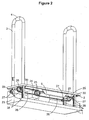
Figure 1 a modular step elevator of a Staircase Elevator Device suitable for ascending/descending any given number of steps of a staircase comprises abase 1 firmly arranged in a non-destructive way on the horizontal surface of the staircase step the modular step elevator is associated with and shaped according to the shape of the horizontal surface of the staircase step and amovable platform 2 having the same shape as thebase 1 and beeing able to be moved up or down between thebase 1 of the modular step elevator and the level of the lower position of the movable platform of the modular step elevator associated with the next higher staircase step by means of an electric, pneumatic or hydraulic actuator. The base can be metallic and/or wooden and has the shape of the horizontal surface of the staircase step, to which it is assigned. - The
movable platform 2 shown inFigure 1 has twohandholds 3 beeing arranged at opposite sides of themovable platform 2 verticaly to the riser and to themovable platform 2, whereby the actuator of the is modular step elevator is controllable by a user by means of control means 4 provided on at least onehandhold 3 of themovable platform 2. - According to the embodiment shown in
Figure 1 themovable platform 2 is electrically driven by means of anelectric motor 6 and preferablytrapezoidal screws 5 fixed vertically near the corners of thebase 1 and passing through holes of themovable platform 2. In the embodiment shown infigure 1 the motor is a 12V motor with a housing vertically fixed on top of the themovable platform 2. At least one suitable, recharchable battery for providing the electric energy for themotor 6 of the modular step elevators of the Staircase Elevator Device is provided (not shown). - As can be taken from
Figure 1 themotor 6 drives afirst motor pulley 7 which is connected by means of afirst timing belt 8 with acentral reduction pulley 9 which is arranged on ashaft 10 on which a second and athird pulley third pulley shaft 10. The second andthird pulley third belts peripheral pulleys peripheral pulley nut 19 on eachtrapezoidal screw 5, screwing or unscrewing them along the trapezoidal screws 5, thus converting the rotational movement into an up or down movement and driving the inner rings of theball bearings 20 to ascent or descent, whereby the outer rings of theball bearings 20 are fixed to themovable platform 2. The inner rings of thebearings 20 are revolved by the trapezoidal nuts 19. A can be taken byFigure 1 , thetrapezoidal screws 5 are partialy guided (the upper part thereof depending on the movement of the movable platform 2) through thehandholds 3, which are configured as hollow bodies. In order to show this feature a part of the left part of theleft handhold 3 is not shown so that the upper part of thescrew 5 guided through the handhold can bee seen. - Moreover the modular step elevator comprises a
height adjustment screw 21 which is preadjusted to stop the movement of themovable platform 2 at the level of the lower position of the movable platform of the modular step elevator associated with the next higher staircase step. - As
Figure 1 shows thebases 1 of the modular step elevators associated with one staircase between two floors are firmly connected to each other by means of at least onestable profile 22 in a stable, united and all-integrated Device, whereby the at least oneprofile 22 is running along and parallel to the inclination of the staircase from the lower floor to the higher floor and can serve also as a guide channel for the cables needed for the operation of the actuators of themovable platforms 2. In addition sidevertical plates 23 can be provided which are fixed at one or both sides of thebase 1, on which the at least oneprofile 22 is affixed. - The Staircase Elevator Device also comprises limit-switches and relays used to activate the motors of the modular step elevators in order to be controllable by the user for up or down movement either separately for each modular step elevator or sequentially for all modular step elevators on the staircase steps.
- The embodiment shown in
Figure 2 differs from the embodiment shown inFigure 1 in that the themovable platform 2 is electrically driven by means of anelectric motor 6 andtoothed racks 28 fixed vertically near the corners of thebase 1, passing through proper holes of themovable platform 2 and partialy guided (the upper part thereof depending on the movement of the movable platform 2) through thehandholds 3, which are configured as hollow bodies. - As shown in
Figure 2 themotor 6 is coupled to agear box 24 for speed reduction, whereby the momentum is transferred from thegear box 24 bysprockets 25 andchains 26 toperipheral gears 27 arranged onaxles 29 according to the principle of a chain drive, which are movable up or down along theracks 28, thus carrying upwards or downwards themovable platform 2, at which the ends of theaxles 29 are rotatably fixed. The peripheral gears 27, engaged to theracks 28 provide synchronous and parallel movement of themovable platform 2 by elevating it at the preadjusted height by a height adjustment screw shown inFigure 1 at the level of the lower position of the movable platform of the modular step elevator associated with the next higher staircase step. In addition roller means 30 assigned to eachrack 28 arranged on axles can be provided to avoid friction between theracks 28 and to ensure a smooth movement of themovable platform 2. - The embodiment shown in
Figure 3 differs from the embodiment shown infigure 1 in that the themovable platform 2 is pneumatically or hydraulically driven by means of pneumatic orhydraulic cylinders 31 andtoothed racks 32, fixed vertically near the corners of thebase 1, passing through proper holes of themovable platform 2 and partialy guided (the upper part thereof depending on the movement of the movable platform 2) through thehandholds 3, which are configured as hollow bodies. - The
cylinders 31 are fixed vertically at both sides on the top of themovable platform 2 and havepiston rods 33 fixed on thebase 1, initiating the up or down movement of themovable platform 2. The compressed air or oil moves thepistons rods 33 depending on the operation mode up or down, thus changing the distance between thebase 1 and themovable platform 2. - The compressed air or oil of an air compressor or oil pump moves through a tubing and corresponding air or oil valves the
piston rods 33 vertically and in synchronous mode, which are movable theplatform 2 at a height preadjusted by a height adjustment screw (not shown). - The movement of the
movable platform 2 can be supported byperipheral gears 34, engaged to theracks 32, providing synchronous up or down movement of themovable platform 2. Within this context achain 37,sprockets 35 andaxles 36 are provided, transferring synchronous rotation toperipheral gears 34 engaged to theracks 32, whereby for each side of the modular step elevator anaxle 36 is provided, on which asprocket 35 and gears 34 assigned to theracks 32 are firmly arranged. Thesprockets 35 of both sides are connected to reach other by means of a revolvingchain 37 for synchronization. In addition roller means 30 assigned to eachrack 32 arranged on axles can be provided to avoid friction between theracks 32 and to ensure a smooth movement of themovable platform 2. - An air-Compressor or oil-pump is installed separately and close to the staircase, providing compressed air or oil to the
cylinders 31. The Staircase Elevator Device also comprises flow controls for regulating the upwards or downwards speed of themovable platform 2, either separately for eachmovable platform 2 or sequentially for allmovable platforms 2 on the staircase steps. - The
bases 1 of the modular step elevators associated with one staircase between two associated with one staircase between two floors are firmly connected to each other by means of at least one stable profilen in a stable, united and all-integrated Device, whereby the profile Is running along and parallel to the inclination of the staircase from the lower floor to the higher floor and can serve as a guide channel for the cables and the tubing needed for the operation of the pneumatic or hydraulic cylinders of themovable platforms 2. -
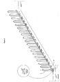
Figure 4 shows a Staircase Elevator Device according to the invention comprising 18 modular step elevators installed on a staircase having 18 steps. The bases of the modular step elevators associated with the staircase are firmly connected to each other by means of astable profile 22 running along and parallel to the inclination of the staircase from the lower floor to the higher floor. - According to the invention and with reference to
Figure 5 the operation of the Staircase Elevator Device for ascending is as follows: The user holds the handholds of the lowest 'first' modular staircase elevator and stands on its movable platform (figure 5a ). By pressing an "up" button on the handhold or by suitably operating a control stick the 'first' platform ascents to the level of the next, 'second' movable platform of the modular staircase elevator associated with the next higher staircase step, which is in the lower position (Figure 5b ). - The two movable platforms are at this stage at the same level and the user holds the
handholds 3 of the second movable platform and moves from the 'first' on the 'second' movable platform and stands on it (Figure 5b ). By pressing the "up" push button or by suitably operating a control stick on the handhold the 'second' movable platform he ascents to the level of the next 'third' movable platform (Figure 5c, Figure 5d ) and so on and so forth until the 17th step (Figure 5e ) and the higher floor is reached (Figure 5f ). The same procedure as for ascenting applies for descending the stairs of the staircase by pressing the "down" button or by suitably operating a control stick of therespective handholds 3. - While the operation has been described above as being a series of finite, sequential steps, the various operations can be actuated in a fairly rapid and fluid sequence, allowing the user to move smoothly and reasonably rapidly from the lower to the highetr floor or vice versa.
Claims (10)
- Staircase Elevator Device for ascending/descending any given number of steps of a staircase comprising an equal to the staircase steps number of modular step elevators, each individual modular step elevator being associated with one step of the staircase, each modular step elevator comprising a base (1) firmly arranged on the horizontal surface of the staircase step the modular step elevator is associated with and shaped according to the shape of the horizontal surface of the staircase step and a movable platform (2) having the same shape as the base and beeing able to be moved up or down between the base (1) of the modular step elevator and the level of the lower position of the movable platform (2) of the modular step elevator associated with the next higher staircase step by means of an electric, pneumatic or hydraulic actuator, the movable platform (2) having at least one handhold (3) beeing arranged on one side of the movable platform (2) essentialy verticaly to the riser and to the movable platform (2), whereby the electric, pneumatic or hydraulic actuator is controllable by a user by means of control means (4) provided on at least one handhold (3) of the movable platform, whereby the first step is an area of the floor level of the lower floor and the last step an area of the floor level of the higher floor, the last step beeing not associated with a modular step elevator, whereby the movable platform (2) of the modular step elevator associated with the second last step is able to be moved up or down between the base (1) and the level of the floor level of the higher floor, characterized in that each individual modular step elevator associated with one step of the staircase is connected with the step in a non-destructive way, in that the modular step elevators are firmly combined by one or two long metal profiles in a stable, united and all-integrated Device and in that the bases (1) of the modular step elevators associated with one staircase between two floors are firmly connected to each other by means of at least one stable profile (22) running along and parallel to the inclination of the staircase from the lower floor to the higher floor and serving also as a guide channel for the cables and/or tubing needed for the operation of the actuators of the movable platforms (2).
- Staircase Elevator Device according to claim 1, characterized in that the movable platform (2) is electrically driven by means of an electric motor (6) and trapezoidal screws (5) fixed vertically near the corners of the base (1) and passing through holes of the movable platform (2), the motor (6) driving a first motor pulley (7) which is connected by means of a first timing belt (8) with a central reduction pulley (9) which is arranged on a shaft (10) on which a second and a third pulley (11, 12) are arranged, whereby the first, second and third pulley are rotating with the shaft (10) and the second and third pulley (11, 12) transfer momentum by means of second and third belts (13, 14) to peripheral pulleys (15, 16, 17, 18), each peripheral pulley (15, 16, 17, 18) driving a nut (19) on each trapezoidal screw (5), screwing or unscrewing them along the trapezoidal screws (5), thus converting the rotational movement into an up or down movement and driving the inner rings of ball bearings (20) to ascent or descent, whereby the outer rings of the ball bearings, (20) are fixed to the movable platform (2) and the inner rings of the bearings (20) are revolved by the trapezoidal nuts (19).
- Staircase Elevator Device according to claim 1, characterized in that the movable platform (2) is electrically driven by means of an electric motor (6) and toothed racks (28) fixed vertically near the corners of the base (1) and passing through proper holes of the movable platform (2) the motor (6) being coupled to a gear box (24) for speed reduction, whereby the momentum is transferred from the gear box (24) by sprockets (25) and chains (26) to peripheral gears (27) arranged on axles (29), which are movable up or down along the racks (28), thus carrying upwards or downwards the movable platform (2), at which the ends of the axles (29) are fixed, whereby the peripheral gears (27), engaged to the racks (28) provide synchronous and parallel movement of the movable platform (2).
- Staircase Elevator Device according to claim 1, characterized in that the movable platform (2) is pneumatically or hydraulically driven by means of pneumatic or hydraulic cylinders (31) and toothed racks (32), fixed vertically near the corners of the base (1) and passing through proper holes of the movable platform (2), the cylinders (31) being fixed vertically at both sides on the top of the movable platform (2) and having piston rods (33) fixed on the base (1), initiating the up or down movement of the movable platform (2), whereby the compressed air or oil moves the pistons rods (33) vertically and in synchronous mode up or down, thus changing the distance between the base (1) and the movable platform (2).
- Staircase Elevator Device according to claim 4, characterized in that the movement of the movable platform (2) is supported by peripheral gears (34), engaged to the racks (32), providing synchronous up or down movement of the movable platform (2), whereby a chain (37), axles (36) and sprockets (35) are provided, transferring synchronous rotation to the peripheral gears (34), whereby for each side of the modular step elevator an axle (36) is provided, on which a sprocket (35) and gears (34) assigned to the racks (32) are firmly arranged, the sprockets (35) of both sides being connected to eachother by means of a revolving chain (37) for synchronization.
- Staircase Elevator Device according to claim 2, 3, 4 or 5, characterized in that each modular step elevator comprises a height adjustment screw (21) which is preadjusted to stop the movement of the movable platform (2) at the level of the lower position of the movable platform (2) of the modular step elevator associated with the next higher staircase step.
- Staircase Elevator Device according to claim 1, 2, 3, 4, 5 or 6, characterized in that the control means (4) are control buttons or a control stick.
- Method for operating a Staircase Elevator Device according to any of the preceding claims characterized in that a user holds the handholds (3) of the lowest 'first' modular staircase elevator and stands on its movable platform whereby by pressing an "up" button on the handhold or by suitably operating a control stick the 'first' movable platform (2) ascents to the level of the next, 'second' movable platform (2) of the modular staircase elevator associated with the next higher staircase step, which is in the lower position, thus the two movable platforms (2) being at the same level, whereby in a next step the user holds the handholds of the "second" movable platform and moves from the 'first' on the 'second' movable platform (2) and stands on it, whereby by pressing the "up" push button or by suitably operating a control stick on the handhold (3) the 'second' movable platform (2) he ascents to the level of the next 'third' movable platform (2) and so on and so forth until the higher floor is reached, whereby the same procedure as for ascenting applies for descending the stairs of the staircase by pressing the "down" button or by suitably operating a control stick of the respective handholds (3).
- Method for operating a Staircase Elevator Device according to claim 8, characterized in that the handholds (3) of each movable platform (2) comprise a touch sensor, whereby the movement of a movable platform (2) starts when the touch sensor is dampened for a predefined time.
- Method for operating a Staircase Elevator Device according to any of the prededing claims 1-7, characterized in that the process of ascending and descending is automated, whereby the movable platforms (2) are moved sequentially up or down according to the operation mode at predefined, adjustable time intervals, whereby in case the time intervals are too short or problems arise the user can operate an alarm button arranged on the handholds (3) stopping the movement.
Priority Applications (3)
| Application Number | Priority Date | Filing Date | Title |
|---|---|---|---|
| PL14156811.3T PL2913290T3 (en) | 2014-02-26 | 2014-02-26 | Staircase elevator device |
| EP14156811.3A EP2913290B1 (en) | 2014-02-26 | 2014-02-26 | Staircase elevator device |
| CY20161100691T CY1117789T1 (en) | 2014-02-26 | 2016-07-15 | SCALE STATION LIFE MECHANISM |
Applications Claiming Priority (1)
| Application Number | Priority Date | Filing Date | Title |
|---|---|---|---|
| EP14156811.3A EP2913290B1 (en) | 2014-02-26 | 2014-02-26 | Staircase elevator device |
Publications (2)
| Publication Number | Publication Date |
|---|---|
| EP2913290A1 EP2913290A1 (en) | 2015-09-02 |
| EP2913290B1 true EP2913290B1 (en) | 2016-04-27 |
Family
ID=50159135
Family Applications (1)
| Application Number | Title | Priority Date | Filing Date |
|---|---|---|---|
| EP14156811.3A Active EP2913290B1 (en) | 2014-02-26 | 2014-02-26 | Staircase elevator device |
Country Status (3)
| Country | Link |
|---|---|
| EP (1) | EP2913290B1 (en) |
| CY (1) | CY1117789T1 (en) |
| PL (1) | PL2913290T3 (en) |
Families Citing this family (1)
| Publication number | Priority date | Publication date | Assignee | Title |
|---|---|---|---|---|
| IT201600071622A1 (en) * | 2016-07-08 | 2018-01-08 | Giovanni Teglia | AUXILIARY DEVICE TO GO UP / DOWN STAIRS |
Family Cites Families (1)
| Publication number | Priority date | Publication date | Assignee | Title |
|---|---|---|---|---|
| NL2004022C2 (en) * | 2009-12-24 | 2011-09-09 | Univ Twente | TREDELIFTS COMPOSITION, TREDELIFT AND METHOD. |
-
2014
- 2014-02-26 EP EP14156811.3A patent/EP2913290B1/en active Active
- 2014-02-26 PL PL14156811.3T patent/PL2913290T3/en unknown
-
2016
- 2016-07-15 CY CY20161100691T patent/CY1117789T1/en unknown
Also Published As
| Publication number | Publication date |
|---|---|
| EP2913290A1 (en) | 2015-09-02 |
| PL2913290T3 (en) | 2016-11-30 |
| CY1117789T1 (en) | 2017-05-17 |
Similar Documents
| Publication | Publication Date | Title |
|---|---|---|
| US8776917B2 (en) | Stair-climbing apparatus | |
| KR101090782B1 (en) | Stair combined use strait type lift device and the operating method | |
| JP7069146B2 (en) | Mobility aid device to overcome height differences | |
| KR102153477B1 (en) | a lift device for the handicapped people | |
| CN111350321A (en) | Deformable stair capable of being deformed into sliding ladder | |
| EP2913290B1 (en) | Staircase elevator device | |
| RU81981U1 (en) | LIFT FOR SMALL POPULATIONS | |
| US8104600B2 (en) | Escalator | |
| CN104477740A (en) | Single-person goods lifting device | |
| CN107758477A (en) | Downstairs power assisting device on the double Suo Chuandong of layer-stepping | |
| CN111362102B (en) | Villa stairway with elevator and working method thereof | |
| CN113387258B (en) | Electric lifting stair | |
| KR102499849B1 (en) | Variable expression stairs device for stage lift | |
| CN211812915U (en) | Rail-mounted corridor elevator | |
| Parab | Lifts and escalators-Transportation system in buildings | |
| JPH06263364A (en) | Manually powered car elevating device | |
| JP2984237B2 (en) | Stair lift | |
| RU2509711C2 (en) | Lifter for straight stair flights | |
| CN213894836U (en) | Rail-mounted stair climbing machine | |
| CN217376926U (en) | Automatic stair climbing device | |
| RU105900U1 (en) | DEVICE FOR LIFTING AND MOVING DISABLED Wheelchairs ON LADDER MARCHES OF MULTI-STOREY BUILDINGS | |
| CN213894835U (en) | Lifter for persons with mobility disabilities | |
| RU2462408C1 (en) | Stair elevator | |
| JPH0530063U (en) | lift device | |
| JP2500370B2 (en) | Stair lift for people with disabilities |
Legal Events
| Date | Code | Title | Description |
|---|---|---|---|
| PUAI | Public reference made under article 153(3) epc to a published international application that has entered the european phase |
Free format text: ORIGINAL CODE: 0009012 |
|
| 17P | Request for examination filed |
Effective date: 20140710 |
|
| AK | Designated contracting states |
Kind code of ref document: A1 Designated state(s): AL AT BE BG CH CY CZ DE DK EE ES FI FR GB GR HR HU IE IS IT LI LT LU LV MC MK MT NL NO PL PT RO RS SE SI SK SM TR |
|
| AX | Request for extension of the european patent |
Extension state: BA ME |
|
| GRAP | Despatch of communication of intention to grant a patent |
Free format text: ORIGINAL CODE: EPIDOSNIGR1 |
|
| INTG | Intention to grant announced |
Effective date: 20151023 |
|
| GRAS | Grant fee paid |
Free format text: ORIGINAL CODE: EPIDOSNIGR3 |
|
| GRAA | (expected) grant |
Free format text: ORIGINAL CODE: 0009210 |
|
| AK | Designated contracting states |
Kind code of ref document: B1 Designated state(s): AL AT BE BG CH CY CZ DE DK EE ES FI FR GB GR HR HU IE IS IT LI LT LU LV MC MK MT NL NO PL PT RO RS SE SI SK SM TR |
|
| REG | Reference to a national code |
Ref country code: GB Ref legal event code: FG4D |
|
| REG | Reference to a national code |
Ref country code: CH Ref legal event code: EP |
|
| REG | Reference to a national code |
Ref country code: AT Ref legal event code: REF Ref document number: 794563 Country of ref document: AT Kind code of ref document: T Effective date: 20160515 |
|
| REG | Reference to a national code |
Ref country code: IE Ref legal event code: FG4D |
|
| REG | Reference to a national code |
Ref country code: DE Ref legal event code: R096 Ref document number: 602014001617 Country of ref document: DE |
|
| REG | Reference to a national code |
Ref country code: CH Ref legal event code: NV Representative=s name: ABREMA AGENCE BREVET ET MARQUES, GANGUILLET, CH |
|
| REG | Reference to a national code |
Ref country code: NL Ref legal event code: FP |
|
| REG | Reference to a national code |
Ref country code: SE Ref legal event code: TRGR |
|
| REG | Reference to a national code |
Ref country code: LT Ref legal event code: MG4D |
|
| PG25 | Lapsed in a contracting state [announced via postgrant information from national office to epo] |
Ref country code: LT Free format text: LAPSE BECAUSE OF FAILURE TO SUBMIT A TRANSLATION OF THE DESCRIPTION OR TO PAY THE FEE WITHIN THE PRESCRIBED TIME-LIMIT Effective date: 20160427 Ref country code: NO Free format text: LAPSE BECAUSE OF FAILURE TO SUBMIT A TRANSLATION OF THE DESCRIPTION OR TO PAY THE FEE WITHIN THE PRESCRIBED TIME-LIMIT Effective date: 20160727 Ref country code: FI Free format text: LAPSE BECAUSE OF FAILURE TO SUBMIT A TRANSLATION OF THE DESCRIPTION OR TO PAY THE FEE WITHIN THE PRESCRIBED TIME-LIMIT Effective date: 20160427 |
|
| PG25 | Lapsed in a contracting state [announced via postgrant information from national office to epo] |
Ref country code: LV Free format text: LAPSE BECAUSE OF FAILURE TO SUBMIT A TRANSLATION OF THE DESCRIPTION OR TO PAY THE FEE WITHIN THE PRESCRIBED TIME-LIMIT Effective date: 20160427 Ref country code: RS Free format text: LAPSE BECAUSE OF FAILURE TO SUBMIT A TRANSLATION OF THE DESCRIPTION OR TO PAY THE FEE WITHIN THE PRESCRIBED TIME-LIMIT Effective date: 20160427 Ref country code: HR Free format text: LAPSE BECAUSE OF FAILURE TO SUBMIT A TRANSLATION OF THE DESCRIPTION OR TO PAY THE FEE WITHIN THE PRESCRIBED TIME-LIMIT Effective date: 20160427 Ref country code: PT Free format text: LAPSE BECAUSE OF FAILURE TO SUBMIT A TRANSLATION OF THE DESCRIPTION OR TO PAY THE FEE WITHIN THE PRESCRIBED TIME-LIMIT Effective date: 20160829 Ref country code: ES Free format text: LAPSE BECAUSE OF FAILURE TO SUBMIT A TRANSLATION OF THE DESCRIPTION OR TO PAY THE FEE WITHIN THE PRESCRIBED TIME-LIMIT Effective date: 20160427 |
|
| PG25 | Lapsed in a contracting state [announced via postgrant information from national office to epo] |
Ref country code: BE Free format text: LAPSE BECAUSE OF FAILURE TO SUBMIT A TRANSLATION OF THE DESCRIPTION OR TO PAY THE FEE WITHIN THE PRESCRIBED TIME-LIMIT Effective date: 20160427 |
|
| REG | Reference to a national code |
Ref country code: DE Ref legal event code: R097 Ref document number: 602014001617 Country of ref document: DE |
|
| PG25 | Lapsed in a contracting state [announced via postgrant information from national office to epo] |
Ref country code: EE Free format text: LAPSE BECAUSE OF FAILURE TO SUBMIT A TRANSLATION OF THE DESCRIPTION OR TO PAY THE FEE WITHIN THE PRESCRIBED TIME-LIMIT Effective date: 20160427 Ref country code: SK Free format text: LAPSE BECAUSE OF FAILURE TO SUBMIT A TRANSLATION OF THE DESCRIPTION OR TO PAY THE FEE WITHIN THE PRESCRIBED TIME-LIMIT Effective date: 20160427 Ref country code: CZ Free format text: LAPSE BECAUSE OF FAILURE TO SUBMIT A TRANSLATION OF THE DESCRIPTION OR TO PAY THE FEE WITHIN THE PRESCRIBED TIME-LIMIT Effective date: 20160427 Ref country code: DK Free format text: LAPSE BECAUSE OF FAILURE TO SUBMIT A TRANSLATION OF THE DESCRIPTION OR TO PAY THE FEE WITHIN THE PRESCRIBED TIME-LIMIT Effective date: 20160427 Ref country code: RO Free format text: LAPSE BECAUSE OF FAILURE TO SUBMIT A TRANSLATION OF THE DESCRIPTION OR TO PAY THE FEE WITHIN THE PRESCRIBED TIME-LIMIT Effective date: 20160427 |
|
| REG | Reference to a national code |
Ref country code: GR Ref legal event code: EP Ref document number: 20160401625 Country of ref document: GR Effective date: 20161020 |
|
| PG25 | Lapsed in a contracting state [announced via postgrant information from national office to epo] |
Ref country code: SM Free format text: LAPSE BECAUSE OF FAILURE TO SUBMIT A TRANSLATION OF THE DESCRIPTION OR TO PAY THE FEE WITHIN THE PRESCRIBED TIME-LIMIT Effective date: 20160427 |
|
| PLBE | No opposition filed within time limit |
Free format text: ORIGINAL CODE: 0009261 |
|
| STAA | Information on the status of an ep patent application or granted ep patent |
Free format text: STATUS: NO OPPOSITION FILED WITHIN TIME LIMIT |
|
| 26N | No opposition filed |
Effective date: 20170130 |
|
| PG25 | Lapsed in a contracting state [announced via postgrant information from national office to epo] |
Ref country code: SI Free format text: LAPSE BECAUSE OF FAILURE TO SUBMIT A TRANSLATION OF THE DESCRIPTION OR TO PAY THE FEE WITHIN THE PRESCRIBED TIME-LIMIT Effective date: 20160427 |
|
| PGFP | Annual fee paid to national office [announced via postgrant information from national office to epo] |
Ref country code: IT Payment date: 20170228 Year of fee payment: 4 |
|
| PG25 | Lapsed in a contracting state [announced via postgrant information from national office to epo] |
Ref country code: MC Free format text: LAPSE BECAUSE OF FAILURE TO SUBMIT A TRANSLATION OF THE DESCRIPTION OR TO PAY THE FEE WITHIN THE PRESCRIBED TIME-LIMIT Effective date: 20160427 |
|
| REG | Reference to a national code |
Ref country code: CH Ref legal event code: PL |
|
| REG | Reference to a national code |
Ref country code: SE Ref legal event code: EUG |
|
| REG | Reference to a national code |
Ref country code: NL Ref legal event code: MM Effective date: 20170301 |
|
| PG25 | Lapsed in a contracting state [announced via postgrant information from national office to epo] |
Ref country code: CH Free format text: LAPSE BECAUSE OF NON-PAYMENT OF DUE FEES Effective date: 20170228 Ref country code: LI Free format text: LAPSE BECAUSE OF NON-PAYMENT OF DUE FEES Effective date: 20170228 Ref country code: CY Free format text: LAPSE BECAUSE OF NON-PAYMENT OF DUE FEES Effective date: 20170226 |
|
| REG | Reference to a national code |
Ref country code: IE Ref legal event code: MM4A |
|
| PG25 | Lapsed in a contracting state [announced via postgrant information from national office to epo] |
Ref country code: SE Free format text: LAPSE BECAUSE OF NON-PAYMENT OF DUE FEES Effective date: 20170227 Ref country code: NL Free format text: LAPSE BECAUSE OF NON-PAYMENT OF DUE FEES Effective date: 20170301 |
|
| REG | Reference to a national code |
Ref country code: FR Ref legal event code: ST Effective date: 20171031 |
|
| PG25 | Lapsed in a contracting state [announced via postgrant information from national office to epo] |
Ref country code: LU Free format text: LAPSE BECAUSE OF NON-PAYMENT OF DUE FEES Effective date: 20170226 |
|
| PG25 | Lapsed in a contracting state [announced via postgrant information from national office to epo] |
Ref country code: FR Free format text: LAPSE BECAUSE OF NON-PAYMENT OF DUE FEES Effective date: 20170228 |
|
| PG25 | Lapsed in a contracting state [announced via postgrant information from national office to epo] |
Ref country code: IE Free format text: LAPSE BECAUSE OF NON-PAYMENT OF DUE FEES Effective date: 20170226 |
|
| PG25 | Lapsed in a contracting state [announced via postgrant information from national office to epo] |
Ref country code: PL Free format text: LAPSE BECAUSE OF NON-PAYMENT OF DUE FEES Effective date: 20170226 |
|
| REG | Reference to a national code |
Ref country code: AT Ref legal event code: UEP Ref document number: 794563 Country of ref document: AT Kind code of ref document: T Effective date: 20160427 |
|
| PG25 | Lapsed in a contracting state [announced via postgrant information from national office to epo] |
Ref country code: MT Free format text: LAPSE BECAUSE OF NON-PAYMENT OF DUE FEES Effective date: 20170226 |
|
| GBPC | Gb: european patent ceased through non-payment of renewal fee |
Effective date: 20180226 |
|
| PG25 | Lapsed in a contracting state [announced via postgrant information from national office to epo] |
Ref country code: AL Free format text: LAPSE BECAUSE OF FAILURE TO SUBMIT A TRANSLATION OF THE DESCRIPTION OR TO PAY THE FEE WITHIN THE PRESCRIBED TIME-LIMIT Effective date: 20160427 |
|
| PG25 | Lapsed in a contracting state [announced via postgrant information from national office to epo] |
Ref country code: GB Free format text: LAPSE BECAUSE OF NON-PAYMENT OF DUE FEES Effective date: 20180226 Ref country code: IT Free format text: LAPSE BECAUSE OF NON-PAYMENT OF DUE FEES Effective date: 20180226 |
|
| PG25 | Lapsed in a contracting state [announced via postgrant information from national office to epo] |
Ref country code: HU Free format text: LAPSE BECAUSE OF FAILURE TO SUBMIT A TRANSLATION OF THE DESCRIPTION OR TO PAY THE FEE WITHIN THE PRESCRIBED TIME-LIMIT; INVALID AB INITIO Effective date: 20140226 |
|
| PG25 | Lapsed in a contracting state [announced via postgrant information from national office to epo] |
Ref country code: BG Free format text: LAPSE BECAUSE OF FAILURE TO SUBMIT A TRANSLATION OF THE DESCRIPTION OR TO PAY THE FEE WITHIN THE PRESCRIBED TIME-LIMIT Effective date: 20160427 |
|
| PG25 | Lapsed in a contracting state [announced via postgrant information from national office to epo] |
Ref country code: MK Free format text: LAPSE BECAUSE OF FAILURE TO SUBMIT A TRANSLATION OF THE DESCRIPTION OR TO PAY THE FEE WITHIN THE PRESCRIBED TIME-LIMIT Effective date: 20160427 |
|
| PG25 | Lapsed in a contracting state [announced via postgrant information from national office to epo] |
Ref country code: TR Free format text: LAPSE BECAUSE OF FAILURE TO SUBMIT A TRANSLATION OF THE DESCRIPTION OR TO PAY THE FEE WITHIN THE PRESCRIBED TIME-LIMIT Effective date: 20160427 |
|
| REG | Reference to a national code |
Ref country code: AT Ref legal event code: MM01 Ref document number: 794563 Country of ref document: AT Kind code of ref document: T Effective date: 20190226 |
|
| PG25 | Lapsed in a contracting state [announced via postgrant information from national office to epo] |
Ref country code: AT Free format text: LAPSE BECAUSE OF NON-PAYMENT OF DUE FEES Effective date: 20190226 |
|
| PG25 | Lapsed in a contracting state [announced via postgrant information from national office to epo] |
Ref country code: IS Free format text: LAPSE BECAUSE OF FAILURE TO SUBMIT A TRANSLATION OF THE DESCRIPTION OR TO PAY THE FEE WITHIN THE PRESCRIBED TIME-LIMIT Effective date: 20160827 |
|
| PGFP | Annual fee paid to national office [announced via postgrant information from national office to epo] |
Ref country code: DE Payment date: 20211123 Year of fee payment: 9 |
|
| REG | Reference to a national code |
Ref country code: DE Ref legal event code: R082 Ref document number: 602014001617 Country of ref document: DE Representative=s name: KARAKATSANIS, GEORGIOS, DR., DE |
|
| PGFP | Annual fee paid to national office [announced via postgrant information from national office to epo] |
Ref country code: GR Payment date: 20230202 Year of fee payment: 10 |
|
| REG | Reference to a national code |
Ref country code: DE Ref legal event code: R119 Ref document number: 602014001617 Country of ref document: DE |
|
| PG25 | Lapsed in a contracting state [announced via postgrant information from national office to epo] |
Ref country code: DE Free format text: LAPSE BECAUSE OF NON-PAYMENT OF DUE FEES Effective date: 20230901 |