EP2910445A2 - Method for supporting a driver when passing through a narrowing path and driver assistance system - Google Patents
Method for supporting a driver when passing through a narrowing path and driver assistance system Download PDFInfo
- Publication number
- EP2910445A2 EP2910445A2 EP15154263.6A EP15154263A EP2910445A2 EP 2910445 A2 EP2910445 A2 EP 2910445A2 EP 15154263 A EP15154263 A EP 15154263A EP 2910445 A2 EP2910445 A2 EP 2910445A2
- Authority
- EP
- European Patent Office
- Prior art keywords
- constriction
- vehicle
- track
- category
- driver
- Prior art date
- Legal status (The legal status is an assumption and is not a legal conclusion. Google has not performed a legal analysis and makes no representation as to the accuracy of the status listed.)
- Granted
Links
- 238000000034 method Methods 0.000 title claims abstract description 47
- 230000003068 static effect Effects 0.000 claims abstract description 34
- 238000004458 analytical method Methods 0.000 claims description 7
- 238000013459 approach Methods 0.000 claims description 7
- 238000011161 development Methods 0.000 description 5
- 230000018109 developmental process Effects 0.000 description 5
- 238000010276 construction Methods 0.000 description 3
- 239000003086 colorant Substances 0.000 description 2
- 238000013461 design Methods 0.000 description 2
- 238000011156 evaluation Methods 0.000 description 2
- 238000005259 measurement Methods 0.000 description 2
- 238000007405 data analysis Methods 0.000 description 1
- 230000001419 dependent effect Effects 0.000 description 1
- 239000003550 marker Substances 0.000 description 1
- 238000012545 processing Methods 0.000 description 1
- 238000012552 review Methods 0.000 description 1
- 238000012800 visualization Methods 0.000 description 1
Images


Classifications
-
- B—PERFORMING OPERATIONS; TRANSPORTING
- B60—VEHICLES IN GENERAL
- B60W—CONJOINT CONTROL OF VEHICLE SUB-UNITS OF DIFFERENT TYPE OR DIFFERENT FUNCTION; CONTROL SYSTEMS SPECIALLY ADAPTED FOR HYBRID VEHICLES; ROAD VEHICLE DRIVE CONTROL SYSTEMS FOR PURPOSES NOT RELATED TO THE CONTROL OF A PARTICULAR SUB-UNIT
- B60W50/00—Details of control systems for road vehicle drive control not related to the control of a particular sub-unit, e.g. process diagnostic or vehicle driver interfaces
- B60W50/08—Interaction between the driver and the control system
- B60W50/14—Means for informing the driver, warning the driver or prompting a driver intervention
-
- B—PERFORMING OPERATIONS; TRANSPORTING
- B60—VEHICLES IN GENERAL
- B60W—CONJOINT CONTROL OF VEHICLE SUB-UNITS OF DIFFERENT TYPE OR DIFFERENT FUNCTION; CONTROL SYSTEMS SPECIALLY ADAPTED FOR HYBRID VEHICLES; ROAD VEHICLE DRIVE CONTROL SYSTEMS FOR PURPOSES NOT RELATED TO THE CONTROL OF A PARTICULAR SUB-UNIT
- B60W30/00—Purposes of road vehicle drive control systems not related to the control of a particular sub-unit, e.g. of systems using conjoint control of vehicle sub-units
- B60W30/08—Active safety systems predicting or avoiding probable or impending collision or attempting to minimise its consequences
- B60W30/095—Predicting travel path or likelihood of collision
- B60W30/0956—Predicting travel path or likelihood of collision the prediction being responsive to traffic or environmental parameters
-
- B—PERFORMING OPERATIONS; TRANSPORTING
- B60—VEHICLES IN GENERAL
- B60W—CONJOINT CONTROL OF VEHICLE SUB-UNITS OF DIFFERENT TYPE OR DIFFERENT FUNCTION; CONTROL SYSTEMS SPECIALLY ADAPTED FOR HYBRID VEHICLES; ROAD VEHICLE DRIVE CONTROL SYSTEMS FOR PURPOSES NOT RELATED TO THE CONTROL OF A PARTICULAR SUB-UNIT
- B60W2552/00—Input parameters relating to infrastructure
-
- B—PERFORMING OPERATIONS; TRANSPORTING
- B60—VEHICLES IN GENERAL
- B60W—CONJOINT CONTROL OF VEHICLE SUB-UNITS OF DIFFERENT TYPE OR DIFFERENT FUNCTION; CONTROL SYSTEMS SPECIALLY ADAPTED FOR HYBRID VEHICLES; ROAD VEHICLE DRIVE CONTROL SYSTEMS FOR PURPOSES NOT RELATED TO THE CONTROL OF A PARTICULAR SUB-UNIT
- B60W2554/00—Input parameters relating to objects
Definitions
- the present invention relates to a method for assisting a driver of a vehicle in the passage of a track constriction. Furthermore, the invention relates to a driver assistance system for assisting a driver of a vehicle in the passage of a track constriction with a sensor unit, with which the track constriction in the direction of travel of the vehicle can be detected.
- a method and apparatus for assisting a vehicle operator in the passage of lane constrictions is known.
- image data are acquired from the traffic environment in front of the vehicle in the direction of travel by means of a camera.
- a road constriction can be detected.
- With knowledge of the dimensions of the vehicle is then determined whether and with what security the track constriction can be passed without collision.
- future positions of the vehicle are estimated and displayed to the driver superimposed on the camera image data.
- the present invention has for its object to provide a method and a driver assistance system of the type mentioned, which support the driver of the vehicle in the passage of the track constriction.
- a track constriction in the direction of travel of the vehicle is detected by means of a sensor unit.
- the track constriction is categorized.
- a traffic constriction is assigned a first category if it includes only static limits. It is assigned a second category if it includes dynamic limits.
- a first graphical element for constriction and relative thereto a second graphical element for the vehicle is displayed, the type of representation of the first and / or second graphical element depending on the category of the detected travel constriction.
- a dynamic limitation of a track constriction is understood in this document to mean that the position of the boundary changes during the approach of the vehicle to the track constriction and / or during the passage of the track constriction.
- the presentation of the track constriction to support the driver then takes place as a function of the category, that is, depending on whether the track constriction static or possibly also includes dynamic limits.
- the driver can quickly and intuitively detect whether the track constriction comprises dynamic limits which require special attention when passing the track constriction. In this way, the driver can be assisted in the passage of the track constriction by the inventive method.
- the passage width of the track constriction is determined by means of the sensor unit.
- the passage width of the track constriction relative to the vehicle is represented by means of the first and second graphic elements.
- the ratio of the passage width of the travel constriction represented by the first graphical element to the width of the vehicle represented by the second graphical element may correspond to the actual ratio of the passage width of the travel constriction to the width of the vehicle.
- the first graphical element comprises orientation aids which indicate an extension of the second graphical element of the vehicle into the first graphical element of the track constriction.
- the orientation aids indicate an extension of the first graphic element of the track constriction in the direction of the second graphic element of the vehicle. For example, a corridor is displayed as an extension of the representation of the vehicle, which extends into the first graphical element of the track constriction.
- the display of this corridor can be understood as part of the first graphical element.
- the orientation aids may be guidance lines that visualize to the driver how the distance of the vehicle in the transverse direction from the lateral boundaries of the track constriction is.
- lateral guidance elements are displayed on both sides in addition to the second graphic element, which visualize the lateral distance of the vehicle from the lateral boundaries of the travel path or the constriction in the direction of travel.
- the display of the transverse guide elements is also understood as part of the first graphical element.
- the transverse guide elements may have a fixed relative position to the second graphic element of the vehicle, that is, they are moved with the second graphic element of the vehicle when the vehicle is moving.
- the transverse guide elements are, in particular, arrows which indicate the lateral distance of the vehicle from the travel path at the current position of the vehicle.
- static and dynamic limits of the travel path are detected in the case of a constricted route of the second category.
- static boundaries are then distinguishably represented by dynamic boundaries. Distinctness can be produced, for example, by different colors, clearly distinguishable graphic structures, or by other emphases of dynamic limitations. In this way, the driver can quickly and intuitively detect whether the travel constriction includes a dynamic boundary that requires more attention.
- the position of a dynamic boundary in the direction of travel is detected continuously.
- the representation of the first and / or second graphical element is then continuously adapted to the relative position of the vehicle to the dynamic boundary. In this way, the driver can be supported in particular when passing the dynamic limitation of the track constriction.
- an indication of the width of the track constriction relative to the width of the vehicle is displayed in a track constriction of the second category in addition to the representation as it takes place in the track constriction of the first category.
- This indication of the relative width is in particular numeric or alphanumeric.
- the distance of the left side of the vehicle from the left boundary of the lane constriction and the distance of the right side of the vehicle from the right boundary of the lane constriction may be indicated.
- the information preferably represents the difference between the width of the track constriction and the width of the vehicle. In this case, therefore, the relative transverse position of the vehicle relative to the track constriction is not taken into account. This avoids that the driver is deflected by the occurrence of two lateral distances to the track constriction and by the processing of this information from driving.
- the type of representation may also differ depending on whether the constriction has not yet been reached or whether the vehicle is already in the passage of the constriction.
- This further distinction in the presentation takes into account that the type of support of the driver differs, depending on whether the vehicle is already in the track constriction or not.
- the distance may be displayed until the beginning of the lane constriction.
- the indication of the width of the constriction relative to the width of the vehicle may be displayed in the graphical element at the illustrated constriction, whereas the indication of the width of the constriction of an already passed section of constriction relative to the width of the vehicle is detected when it has been detected that the vehicle is already in the passage of the constriction.
- both the width of the track constriction of an already passed section of the track constriction relative to the width of the vehicle and the width of the track constriction in a forward section of the track constriction relative to the width of the Vehicle are displayed.
- the distance is also displayed until the end of the track constriction, when it has been detected that the vehicle is already in the passage of the track constriction.
- the driver assistance system is characterized by an analysis unit with which the track constriction can be categorized, wherein a lane constriction is assigned a first category if it comprises only static boundaries, and a second category is assigned if it comprises dynamic boundaries.
- the driver assistance system includes a display device configured to generate graphics data that includes, while approaching the lane narrowing and / or during passage of the lane narrowing to assist the driver of the vehicle, a first graphical element for lane constriction and a second graphical element for indicate the track constriction, wherein the type of representation of the first and / or second graphical element differs depending on the category of the detected track constriction.
- the driver assistance system according to the invention is in particular designed to carry out the method according to the invention. It therefore also has the same advantages as the method according to the invention.
- the sensor unit comprises a camera.
- the display device With the display device, at least the first graphical element is superimposed on the image taken by the camera.
- the second graphical element can also be superimposed on the image captured by the camera.
- the driver assistance system comprises a sensor unit 2, which in turn comprises a camera which continuously records images of the travel path of the vehicle in the direction of travel.
- the image data is transmitted to the sensor unit 2 to an analysis unit 3.
- an evaluation of the image data takes place. In particular, the course of the track in the direction of travel is determined. Furthermore, limitations of the travel path are detected. On the basis of this evaluation, it is recognized whether the travel narrows in the direction of travel of the vehicle 1. If such a track constriction has been detected, further, the boundaries that constitute the track constriction are analyzed. In particular, it is determined whether they are static boundaries or dynamic boundaries. Static limits do not change their position within a certain measurement interval. Dynamic limits change their position during the measurement interval. In the case of dynamic limitations, the image data are further analyzed such that the trajectory of the dynamic boundary is determined relative to the fixed route and relative to the own vehicle 1.
- Data for the image data analysis ie in particular both the image data per se and the associated data on a detected constriction, their limitations and the category of constriction, and the trajectories of a dynamic boundary are transmitted from the analysis unit 3 to a display device 4.
- the display device 4 may generate graphics data that assist the driver of the vehicle 1 during the approach to a track constriction and / or during the passage of the track constriction, as will be explained later with reference to an embodiment of the method according to the invention.
- the graphics data are displayed on a display surface 5, which is arranged for example in the combination instrument of the vehicle 1.
- the display area 5 can also be a head-up display.
- the display of the driver assistance system is to assist the driver of the vehicle 1 in the transverse guidance of the vehicle 1 in the passage of bottlenecks, in flowing traffic when driving through bottlenecks or passing car columns in neighboring lanes, standing obstacles or parked vehicles.
- This function of the driver assistance system can be used in particular at low speeds, ie in particular in the city center. However, the driver can also be supported when driving on motorways and highways through this function.
- FIG. 2 a traffic situation is shown in which the track 6 narrows through a pylon alley.
- the track constriction thus has static boundaries 7, which are formed by pylons.
- pylons can track 6 on both sides, as in FIG. 2 shown, or one-sided (not shown) limit.
- the vehicle 1, 1 'drive in the middle of the track 6 to pass the Fahrwegverengung. Since the pylons are static boundaries 7, the in FIG. 2 Track constriction shown assigned to the first category.
- FIG. 3 is shown another example of a constriction of the first category.
- the static boundaries 7 are formed by parked vehicles.
- FIG. 4 is shown another example of a constriction of the first category.
- the guideway 6 is narrowed by parked vehicles as a static boundary 7 as well as by a vehicle parked in the second row as a further static boundary 7.
- FIG. 5 an example of a second-category track constriction is shown.
- the track 6 narrows on the one hand by a static boundary 7.
- a truck on the right side of the guideway 6 within the constriction This truck represents a dynamic limit 8 because it moves relative to the track 6.
- the vehicle 1, 1 in order to pass the track constriction, which is formed by both the static boundary 7 and the dynamic boundary 8, the vehicle 1, 1 'has to travel very far at the left edge of the constriction.
- the driver of the vehicle 1, 1 ' is assisted by the display of the driver assistance system.
- FIG. 6 is shown another example of a congestion narrowing of the second category.
- the driveway is the middle lane of, for example, a highway.
- the traveling traffic ie the vehicles on the tracks to the right and left of the track 6 of the vehicle 1, thereby narrows the track 6 of the middle lane on which the vehicle 1 moves.
- These vehicles of the secondary tracks thus represent dynamic boundaries 8 of a track narrowing of the middle lane.
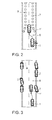
- FIG. 7A the situation is shown in which the vehicle 1 approaches a constriction with a static boundary 7 and a dynamic boundary 8.
- the vehicle 1 is within the track constriction.
- the vehicle 1 is thus located in the passage of the track constriction.
- Fig. 7C the situation is shown in which the vehicle 1 leaves the track constriction.
- a distinction is made in particular between the situation when approaching the track constriction and the situation when passing the track constriction and accordingly different displays are generated on the display area 5.
- image data are recorded continuously in the direction of travel of the vehicle 1 by means of the sensor unit 2.
- the track 6 narrows in the direction of travel of the vehicle 1. If such a track constriction has been detected, it is categorized. In this case, a track narrowing is assigned a first category if it only includes static boundaries 7. On the other hand, if the track constriction also includes dynamic limits 8, the track constriction is assigned a second category.
- a display is generated on the display surface 5 of the display device 4 for assisting the driver of the vehicle 1.
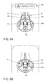
- Fig. 8A Such a display is shown, which is displayed on the display surface 5, when a lane constriction of the first category has been detected and was also determined that the vehicle 1 is still before the track constriction, that is, when the vehicle 1 to the track constriction approaches.
- the first graphic element 9 visualizes the track constriction.
- the second graphical element 10 represents the vehicle 1.
- the relative arrangement of the representations of the first and second graphical elements 9, 10 need not be to scale to the actual dimensions of the track constriction relative to the dimensions and position of the vehicle 1.
- the arrangement and design of the two graphical elements 9, 10 for the track constriction and the vehicle visualizes the dimensions and the position of the track constriction relative to the vehicle 1.
- a notice 15 is displayed on the display surface 5, which contains the indication at which distance from the vehicle 1, the track constriction begins. Furthermore, the previous display of the driver assistance system, which optionally includes representations of the boundaries of the current travel path 6, changes so that the first graphical element 9 is displayed. This comprises on both sides next to the second graphical element 10 for the vehicle lines 11, which visualize the boundary of the travel path 6 on both sides next to the vehicle 1 and in the track constriction.
- the lines 11 are generic, that is, they generally point to the approximation of a track constriction, they do not exactly visualize the nature of the actual limitations of the track constriction. However, the lines 11 represent the extent of the track constriction relative to the vehicle 1 by the jump of the lines 11 at the position of the beginning of the track constriction inward.
- the first graphic element 9 comprises guide lines 12 as orientation aids. These guide lines 12 extend the beginning of the track constriction perpendicular to the direction of travel of the vehicle 1, which is represented by the second graphical element 10. It is in the representation according to Figure 8A chosen a perspective projection.
- the orientations of the first graphical element 9 may further include a graphical representation 19 of a corridor. This corridor extends the width of the second graphic element 10 of the vehicle into the representation of the track constriction through the first graphical element 9.
- the first graphic element 9 still comprises graphic transverse guide elements 13, which are displayed next to the second graphic element 10 for the vehicle 1.
- These transverse guide elements 13 visualize the lateral distance of the vehicle 1 from the lateral boundaries of the travel path 6, when the vehicle 1 is not yet in the Fahrwegverengung, or the Fahrwegverengung when the vehicle 1 is within the Fahrwegverengung.
- the driver of the vehicle 1 can thus estimate the current distance from the boundary of the travel path 6 on the display surface 5 by means of this representation on the basis of the transverse guide elements 13.
- the driver of the vehicle 1 can also estimate the position of the vehicle 1 relative to the beginning of the track constriction and correct if necessary.
- a guide ring 14 is shown around the second graphical element 10 for the vehicle 1, which generally indicates a potential hazard.
- the display is shown on the display surface 5 when it is detected that the vehicle 1 is within the first-category traffic constriction.
- the hint 15 disappears.
- the guide lines 12 disappear.
- the first graphical element 9 includes the lines 11 for limiting the track constriction 6, the transverse guide elements 13 and the guide ring 14.
- the second graphical element 10 for the vehicle 1 is now reproduced within the bottleneck represented by the first graphical element 9.
- the display of a track constriction of the first category thus makes the driver of the vehicle 1 aware of the bottleneck.
- the course of the bottleneck is reproduced as a generic element. It does not change depending on the nature of the restriction or the course of the bottleneck.
- the dimensions of the bottleneck are graphically visualized and the driver is given orientation aids by means of the first graphical element 9. They give the driver the opportunity to make an early estimate of the forward adjustment of the width of the guideway 6. The distance left and right of your own vehicle 1 can thus be estimated even in the approach to the track constriction.
- the nature of the delimiting elements is not taken up by the graphic element 9.
- the static boundaries 7 are pylons, parked vehicles or Schrammborde. It is only taken into account that these are static limitations 7.
- the representation 19 of the corridor By the representation 19 of the corridor, the course of the recommended lane within the track constriction can be further visualized. It can be taken into account that in certain circumstances no central passage through the track constriction is recommended if, for example, there are larger static boundaries 7 on one side than on the other side. In this way, the driver can easily and intuitively anticipate whether the assistance function will be centered or, due to a larger object, closer to a track side.
- the type of static boundary 7 can also be visualized by the first graphic object 9.
- the driver can recognize, for example, whether the track constriction is formed by a pylon lane, by vehicles parked on one or both sides, by a rake rim or combinations of such static limitations 7.
- Figure 9A the display is reproduced when it has been detected that the vehicle 1 is not yet located within the track constriction, but is approaching this track constriction.
- the graphic element 16 is displayed instead of the graphic element 9.
- the difference between the width of the track constriction and the width of the vehicle 1 is indicated. Im in Figure 9A As shown, this difference is 25 cm.
- the indication of the graphic element 17 relates to the width of the track constriction at the beginning of the track constriction relative to the width of the vehicle 1.
- this indication relates to the minimum detected width of the track constriction relative to the width of the vehicle 1 the first graphic element 16, the further graphic elements 11, 12, 13 and 14, which are also displayed in the first graphical element 9, when a first category of traffic constriction is visualized.
- the display is shown on the display surface 5 when the vehicle 1 is within a second-category traffic constriction.
- the display differs from the one in FIG. 8B in that the graphical indication 17 is still displayed with the indication of the width of the track constriction relative to the width of the vehicle 1.
- this indication of the width is shown in perspective behind and below the second graphical element 10 for the vehicle, that is, behind the representation for the vehicle 1 with respect to the direction of travel of the vehicle 1.
- the indication of the width refers in this case on the width of the track constriction next to the current position of the vehicle or immediately before this position.
- the indication of the width can also refer to a review when passing the track constriction.
- the width of the track constriction is displayed immediately behind the vehicle 1 relative to the width of the vehicle 1.
- the further display corresponds to the one in FIG. 8B displayed display for a first category of traffic constriction, if there is no dynamic limit 8 next to or immediately in front of the vehicle 1.
- FIG. 9C reproduced display on the display surface 5 shown.
- the message 20 is displayed, which makes the driver aware that there is a dynamic boundary 8 in the vicinity of the own vehicle 1, which requires increased attention.
- This note 20 is displayed in a color different from the colors of the remaining graphic elements as described above.
- the first graphical element 16 comprises a graphic element 18, which has the dynamic boundary 8 and the position of this dynamic boundary 8 relative to the track constriction and relative to the vehicle 1 by a certain relative position of the graphic element 18 to the second graphical Element 10 and visualized within the first graphical element 16.
- the arrangement of the graphic element 18 on the display surface 5 is continuously adapted to the detected trajectory of the dynamic boundary 8, so that the driver can continuously detect the relative position of the vehicle 1 to the dynamic boundary 8.
- the graphical element 18 is displayed in the same color as the reference 20. In this way, the driver can adjust itself to sudden changes in the position of the dynamic boundary 8 by the additional information of the graphic element 18 and the hint 20. At the same time, it is thus prepared for adjustments to the assistance function of the driver assistance system.
- the dynamic boundary 8 changes its position in the direction of the vehicle 1, this is visualized on the one hand by a change in the position of the graphic object 18.
- the detected length of the track constriction is displayed in the phase of passing the track constriction.
- the driver in this way gains a sense of the duration for which he presumably remains in the situation with the constriction of the track.
- the track constrictions can be supplemented by additional categories.
- the first and / or the second graphical element for the track constriction and for the vehicle 1 can be further displayed differently.
- another category may relate to the recognizability of the track constriction. It can be distinguished in this case between the type of limitation, depending on whether it is continuous, such as in a wall, or is provided with gaps, such as trees, traffic cones or beacons.
- a distinction can be made with regard to the height of the boundary. There are high limits, such as houses and tunnels. Further, there are low limits such as marker buttons, pylons or the like.
Landscapes
- Engineering & Computer Science (AREA)
- Automation & Control Theory (AREA)
- Transportation (AREA)
- Mechanical Engineering (AREA)
- Human Computer Interaction (AREA)
- Traffic Control Systems (AREA)
Abstract
Die vorliegende Erfindung betrifft ein Verfahren zum Unterstützen eines Fahrers eines Fahrzeugs (1) bei der Passage einer Fahrwegverengung, bei dem mittels einer Sensoreinheit (2) eine Fahrwegverengung in Fahrtrichtung des Fahrzeugs (1) erfasst wird, die Fahrwegverengung kategorisiert wird, wobei einer Fahrwegverengung eine erste Kategorie zugeordnet wird, wenn sie nur statische Begrenzungen (7) umfasst, und eine zweite Kategorie zugeordnet wird, wenn sie dynamische Begrenzungen (8) umfasst, und während des Annäherns an die Fahrwegverengung und/oder während der Passage der Fahrwegverengung zum Unterstützen des Fahrers des Fahrzeugs (1) ein erstes graphisches Element (9, 16) für die Fahrwegverengung und relativ dazu ein zweites graphisches Element (10) für das Fahrzeug (1) angezeigt wird, wobei sich die Art der Darstellung des ersten und/oder zweiten graphischen Elements (9, 16, 10) in Abhängigkeit von der Kategorie der erfassten Fahrwegverengung unterscheidet. Des Weiteren betrifft die Erfindung ein Fahrerassistenzsystem zum Ausführen dieses Verfahrens.The present invention relates to a method for assisting a driver of a vehicle (1) in the passage of a track constriction, in which by means of a sensor unit (2) a track constriction in the direction of travel of the vehicle (1) is detected, the track constriction is categorized, wherein a track constriction first category is assigned if it comprises only static boundaries (7) and a second category is assigned if it includes dynamic boundaries (8) and while approaching the constriction and / or during the passage of the constriction to support the driver the vehicle (1) a first graphical element (9, 16) for the track constriction and relative to a second graphical element (10) for the vehicle (1) is displayed, wherein the nature of the representation of the first and / or second graphical element (9, 16, 10) differs depending on the category of the detected travel constriction. Furthermore, the invention relates to a driver assistance system for carrying out this method.
Description
Die vorliegende Erfindung betrifft ein Verfahren zum Unterstützen eines Fahrers eines Fahrzeugs bei der Passage einer Fahrwegverengung. Ferner betrifft die Erfindung ein Fahrerassistenzsystem zum Unterstützen eines Fahrers eines Fahrzeugs bei der Passage einer Fahrwegverengung mit einer Sensoreinheit, mit der die Fahrwegverengung in Fahrtrichtung des Fahrzeugs erfassbar ist.The present invention relates to a method for assisting a driver of a vehicle in the passage of a track constriction. Furthermore, the invention relates to a driver assistance system for assisting a driver of a vehicle in the passage of a track constriction with a sensor unit, with which the track constriction in the direction of travel of the vehicle can be detected.
Aus der
Aus der
Der vorliegenden Erfindung liegt die Aufgabe zugrunde, ein Verfahren und ein Fahrerassistenzsystem der eingangs genannten Art bereitzustellen, welche den Fahrer des Fahrzeugs bei der Passage der Fahrwegverengung unterstützen.The present invention has for its object to provide a method and a driver assistance system of the type mentioned, which support the driver of the vehicle in the passage of the track constriction.
Erfindungsgemäß wird diese Aufgabe durch ein Verfahren mit den Merkmalen des Anspruchs 1 und ein Fahrerassistenzsystem mit den Merkmalen des Anspruchs 14 gelöst. Vorteilhafte Ausgestaltungen und Weiterbildungen ergeben sich aus den abhängigen Ansprüchen.According to the invention, this object is achieved by a method having the features of
Bei dem erfindungsgemäßen Verfahren wird mittels einer Sensoreinheit eine Fahrwegverengung in Fahrtrichtung des Fahrzeugs erfasst. Die Fahrwegverengung wird kategorisiert. Dabei wird einer Fahrwegverengung eine erste Kategorie zugeordnet, wenn sie nur statische Begrenzungen umfasst. Ihr wird hingegen eine zweite Kategorie zugeordnet, wenn sie dynamische Begrenzungen umfasst. Bei dem erfindungsgemäßen Verfahren wird während des Annäherns an die Fahrwegverengung und/oder während der Passage der Fahrwegverengung zum Unterstützen des Fahrers im Fahrzeug ein erstes graphisches Element für die Fahrwegverengung und relativ dazu ein zweites graphisches Element für das Fahrzeug angezeigt, wobei sich die Art der Darstellung des ersten und/oder zweiten graphischen Elements in Abhängigkeit von der Kategorie der erfassten Fahrwegverengung unterscheidet.In the method according to the invention, a track constriction in the direction of travel of the vehicle is detected by means of a sensor unit. The track constriction is categorized. In this case, a traffic constriction is assigned a first category if it includes only static limits. It is assigned a second category if it includes dynamic limits. In the method according to the invention, while approaching the track constriction and / or during passage of the track constriction to assist the driver in the vehicle, a first graphical element for constriction and relative thereto a second graphical element for the vehicle is displayed, the type of representation of the first and / or second graphical element depending on the category of the detected travel constriction.
Unter einer dynamischen Begrenzung einer Fahrwegverengung wird in dieser Schrift verstanden, dass sich die Position der Begrenzung während des Annäherns des Fahrzeugs an die Fahrwegverengung und/oder während der Passage der Fahrwegverengung verändert.A dynamic limitation of a track constriction is understood in this document to mean that the position of the boundary changes during the approach of the vehicle to the track constriction and / or during the passage of the track constriction.
Im Zuge der Weiterentwicklung von Fahrerassistenzsystemen ergibt sich das Bedürfnis den Fahrer bei Fahrwegverengungen kontinuierlich zu unterstützen. Diese Unterstützung ist bei Fahrwegverengungen auf Autobahnen, beispielsweise bei Baustellen, oder im Stadtverkehr wichtig. Eine besondere Bedeutung hat hierbei die kontinuierliche Querführung im fließenden Verkehr, um den Fahrer beim Durchfahren von Engstellen, bei der Vorbeifahrt an Fahrzeugkolonnen in Nachbarfahrspuren, an stehenden Hindernissen oder parkenden Fahrzeugen zu unterstützen. Zudem sollte der Fahrer gewarnt werden, wenn die Fahrwegverengung zu schmal für eine Durchfahrt ist. Die Unterstützung des Fahrers kann dabei sowohl in der teilautomatisierenden Führung des Fahrzeugs als auch in einer unterstützenden Darstellung der Fahrzeugumgebung liegen. Hierbei ist es wichtig dem Fahrer die Systemzustände zu visualisieren, damit er Vertrauen in die Assistenzfunktionen aufbaut.In the course of further development of driver assistance systems, there is a need to continuously support the driver in the case of constrictions. This support is important for constrictions on motorways, for example at construction sites, or in city traffic. Of particular importance here is the continuous transverse guidance in flowing traffic in order to assist the driver when driving through bottlenecks, when passing car columns in neighboring lanes, at stationary obstacles or parked vehicles. In addition, the driver should be warned when the track constriction is too narrow for a passage. The assistance of the driver can lie both in the partially automated guidance of the vehicle and in a supporting representation of the vehicle environment. It is important for the driver to visualize the system conditions so that he builds trust in the assistance functions.
Es hat sich herausgestellt, dass es bei einer Fahrwegverengung in Fahrtrichtung des Fahrzeugs von besonderer Bedeutung ist, ob der Fahrweg von statischen oder dynamischen Begrenzungen gebildet wird. Bei dem erfindungsgemäßen Verfahren wird dieser Unterschied der Fahrwegverengung erfasst, so dass die Fahrwegverengung unterschiedlich kategorisiert werden kann.It has been found that it is of particular importance in the case of a travel constriction in the direction of travel of the vehicle whether the travel path is formed by static or dynamic limits. In the method according to the invention, this difference in the track constriction is detected so that the track constriction can be categorized differently.
Die Darstellung der Fahrwegverengung zum Unterstützen des Fahrers erfolgt dann in Abhängigkeit von der Kategorie, das heißt in Abhängigkeit davon, ob die Fahrwegverengung statische oder ggf. zusätzlich auch dynamische Begrenzungen umfasst. Vorteilhafterweise kann der Fahrer auf diese Weise schnell und intuitiv erfassen, ob die Fahrwegverengung dynamische Begrenzungen umfasst, welche eine besondere Aufmerksamkeit beim Passieren der Fahrwegverengung erfordern. Auf diese Weise kann der Fahrer bei der Passage der Fahrwegverengung durch das erfindungsgemäße Verfahren unterstützt werden.The presentation of the track constriction to support the driver then takes place as a function of the category, that is, depending on whether the track constriction static or possibly also includes dynamic limits. Advantageously, in this way, the driver can quickly and intuitively detect whether the track constriction comprises dynamic limits which require special attention when passing the track constriction. In this way, the driver can be assisted in the passage of the track constriction by the inventive method.
Gemäß einer Weiterbildung des erfindungsgemäßen Verfahrens wird mittels der Sensoreinheit die Durchfahrtsbreite der Fahrwegverengung bestimmt. Mittels des ersten und zweiten graphischen Elements wird die Durchfahrtsbreite der Fahrwegverengung relativ zum Fahrzeug dargestellt. Beispielsweise kann das Verhältnis der vom ersten graphischen Element dargestellten Durchgangsbreite der Fahrwegverengung zu der von dem zweiten graphischen Element dargestellten Breite des Fahrzeugs dem tatsächlichen Verhältnis der Durchfahrtsbreite der Fahrwegverengung zu der Breite des Fahrzeugs entsprechen. Auf diese Weise wird dem Fahrer des Fahrzeugs maßstabsgetreu die Breite des eigenen Fahrzeugs relativ zu der Durchfahrtsbreite der Fahrwegverengung visualisiert. Vorteilhafterweise wird hierdurch der Fahrer bei Passage der Fahrwegverengung unterstützt.According to a development of the method according to the invention, the passage width of the track constriction is determined by means of the sensor unit. The passage width of the track constriction relative to the vehicle is represented by means of the first and second graphic elements. For example, the ratio of the passage width of the travel constriction represented by the first graphical element to the width of the vehicle represented by the second graphical element may correspond to the actual ratio of the passage width of the travel constriction to the width of the vehicle. In this way, the driver of the vehicle to scale the width of the own vehicle is visualized relative to the passage width of the track constriction. Advantageously, thereby the driver is supported in passage of the track constriction.
Gemäß einer Weiterbildung des erfindungsgemäßen Verfahrens werden bei einer Fahrwegverengung der ersten Kategorie einseitig oder beidseitig des Fahrwegs statische Begrenzungen erfasst, welche den Fahrweg verengen. Das erste und zweite graphische Element werden dann so dargestellt, dass die Entfernung des Fahrzeugs von dem Beginn der Fahrwegverengung und die Querposition des Fahrzeugs relativ zu den statischen Begrenzungen der Fahrwegverengung erkennbar sind. Auf diese Weise kann der Fahrer erkennen, ob er sich zu weit rechts oder zu weit links relativ zu dem Beginn der Fahrwegverengung befindet.According to a further development of the method according to the invention, in the case of a narrowing of the first category on one or both sides of the travel path, static limitations are detected which narrow the travel path. The first and second graphical elements are then displayed so that the distance of the vehicle from the beginning of the track constriction and the transverse position of the vehicle relative to the static limitations of the track constriction are recognizable. In this way, the driver can detect if he is too far to the right or too far left relative to the beginning of the track constriction.
Bevorzugt umfasst das erste graphische Element Orientierungshilfen, welche eine Verlängerung des zweiten graphischen Elements des Fahrzeugs in das erste graphische Element der Fahrwegverengung hinein anzeigen. Alternativ oder zusätzlich können gemäß einer anderen Ausgestaltung des erfindungsgemäßen Verfahrens die Orientierungshilfen eine Verlängerung des ersten graphischen Elements der Fahrwegverengung in Richtung des zweiten graphischen Elements des Fahrzeugs anzeigen. Beispielsweise wird ein Korridor als Verlängerung der Darstellung des Fahrzeugs angezeigt, der in das erste graphische Element der Fahrwegverengung hineinreicht.Preferably, the first graphical element comprises orientation aids which indicate an extension of the second graphical element of the vehicle into the first graphical element of the track constriction. Alternatively or additionally, according to another embodiment of the method according to the invention, the orientation aids indicate an extension of the first graphic element of the track constriction in the direction of the second graphic element of the vehicle. For example, a corridor is displayed as an extension of the representation of the vehicle, which extends into the first graphical element of the track constriction.
Dabei kann die Anzeige dieses Korridors als Teil des ersten graphischen Elements aufgefasst werden. Des Weiteren können die Orientierungshilfen Führungslinien sein, welche dem Fahrer visualisieren, wie der Abstand des Fahrzeugs in Querrichtung von den seitlichen Begrenzungen der Fahrwegverengung ist.The display of this corridor can be understood as part of the first graphical element. Furthermore, the orientation aids may be guidance lines that visualize to the driver how the distance of the vehicle in the transverse direction from the lateral boundaries of the track constriction is.
Gemäß einer weiteren Ausgestaltung des erfindungsgemäßen Verfahrens werden beidseitig neben dem zweiten graphischen Element Querführungselemente angezeigt, welche den seitlichen Abstand des Fahrzeugs von den seitlichen Begrenzungen des Fahrwegs oder der Fahrwegverengung in Fahrtrichtung visualisieren. Die Anzeige der Querführungselemente wird auch als Teil des ersten graphischen Elements aufgefasst. Die Querführungselemente können insbesondere eine feste Relativposition zu dem zweiten graphischen Element des Fahrzeugs haben, das heißt sie werden mit dem zweiten graphischen Element des Fahrzeugs mitbewegt, wenn sich das Fahrzeug bewegt. Die Querführungselemente sind insbesondere Pfeile, die den seitlichen Abstand des Fahrzeugs von dem Fahrweg bei der aktuellen Position des Fahrzeugs anzeigt. Durch die Anzeige der Querführungselemente wird der Fahrer bei der Annäherung an die Fahrwegverengung sowie bei der Passage durch die Fahrwegverengung unterstützt.According to a further embodiment of the method according to the invention, lateral guidance elements are displayed on both sides in addition to the second graphic element, which visualize the lateral distance of the vehicle from the lateral boundaries of the travel path or the constriction in the direction of travel. The display of the transverse guide elements is also understood as part of the first graphical element. In particular, the transverse guide elements may have a fixed relative position to the second graphic element of the vehicle, that is, they are moved with the second graphic element of the vehicle when the vehicle is moving. The transverse guide elements are, in particular, arrows which indicate the lateral distance of the vehicle from the travel path at the current position of the vehicle. By displaying the transverse guide elements, the driver is assisted in approaching the track constriction and in the passage through the Fahrwegverengung.
Bei einer Weiterbildung des erfindungsgemäßen Verfahrens werden bei einer Fahrwegverengung der zweiten Kategorie statische und dynamische Begrenzungen des Fahrwegs erfasst. Bei dem ersten graphischen Element werden dann statische Begrenzungen unterscheidbar von dynamischen Begrenzungen dargestellt. Die Unterscheidbarkeit kann beispielsweise durch unterschiedliche Farben, klar unterscheidbare graphische Strukturen oder durch andere Hervorhebungen der dynamischen Begrenzungen hergestellt werden. Auf diese Weise kann der Fahrer schnell und intuitiv erfassen, ob die Fahrwegverengung eine dynamische Begrenzung umfasst, welche höhere Aufmerksamkeit erfordert.In a further development of the method according to the invention, static and dynamic limits of the travel path are detected in the case of a constricted route of the second category. In the first graphical element, static boundaries are then distinguishably represented by dynamic boundaries. Distinctness can be produced, for example, by different colors, clearly distinguishable graphic structures, or by other emphases of dynamic limitations. In this way, the driver can quickly and intuitively detect whether the travel constriction includes a dynamic boundary that requires more attention.
Bei dem erfindungsgemäßen Verfahren wird insbesondere die Position einer dynamischen Begrenzung in Fahrtrichtung fortwährend erfasst. Die Darstellung des ersten und/oder zweiten graphischen Elements wird dann fortwährend an die Relativposition des Fahrzeugs zu der dynamischen Begrenzung angepasst. Auf diese Weise kann der Fahrer insbesondere beim Passieren der dynamischen Begrenzung der Fahrwegverengung unterstützt werden.In the method according to the invention, in particular, the position of a dynamic boundary in the direction of travel is detected continuously. The representation of the first and / or second graphical element is then continuously adapted to the relative position of the vehicle to the dynamic boundary. In this way, the driver can be supported in particular when passing the dynamic limitation of the track constriction.
Gemäß einer weiteren Ausgestaltung des erfindungsgemäßen Verfahrens wird bei einer Fahrwegverengung der zweiten Kategorie zusätzlich zu der Darstellung, wie sie bei der Fahrwegverengung der ersten Kategorie erfolgt, eine Angabe der Breite der Fahrwegverengung relativ zu der Breite des Fahrzeugs angezeigt. Diese Angabe der relativen Breite erfolgt insbesondere numerisch oder alphanumerisch.According to a further embodiment of the method according to the invention, an indication of the width of the track constriction relative to the width of the vehicle is displayed in a track constriction of the second category in addition to the representation as it takes place in the track constriction of the first category. This indication of the relative width is in particular numeric or alphanumeric.
Beispielsweise kann der Abstand der linken Seite des Fahrzeugs von der linken Begrenzung der Fahrwegverengung und der Abstand der rechten Seite des Fahrzeugs von der rechten Begrenzung der Fahrwegverengung angegeben werden. Bevorzugt stellt bei dem erfindungsgemäßen Verfahren jedoch die Angabe die Differenz der Breite der Fahrwegverengung und der Breite des Fahrzeugs dar. Es wird in diesem Fall somit nicht die relative Querposition des Fahrzeugs zu der Fahrwegverengung berücksichtigt. Hierdurch wird vermieden, dass der Fahrer durch die Angabe von zwei seitlichen Abständen zu der Fahrwegverengung und durch die Verarbeitung dieser Information vom Fahrgeschehen abgelenkt wird.For example, the distance of the left side of the vehicle from the left boundary of the lane constriction and the distance of the right side of the vehicle from the right boundary of the lane constriction may be indicated. In the method according to the invention, however, the information preferably represents the difference between the width of the track constriction and the width of the vehicle. In this case, therefore, the relative transverse position of the vehicle relative to the track constriction is not taken into account. This avoids that the driver is deflected by the occurrence of two lateral distances to the track constriction and by the processing of this information from driving.
Gemäß einer Weiterbildung des erfindungsgemäßen Verfahrens wird erfasst, ob das Fahrzeug die Fahrwegverengung bereits erreicht hat oder ob sich das Fahrzeug bereits in der Passage der Fahrwegverengung befindet. In diesem Fall kann sich die Art der Darstellung ferner in Abhängigkeit davon unterscheiden, ob die Fahrwegverengung noch nicht erreicht wurde oder ob sich das Fahrzeug bereits in der Passage der Fahrwegverengung befindet. Diese weitere Unterscheidung bei der Darstellung berücksichtigt, dass sich die Art der Unterstützung des Fahrers unterscheidet, je nachdem, ob sich das Fahrzeug bereits in der Fahrwegverengung befindet oder nicht.According to one embodiment of the method according to the invention, it is detected whether the vehicle has already reached the track constriction or whether the vehicle is already in the passage of the track constriction. In this case, the type of representation may also differ depending on whether the constriction has not yet been reached or whether the vehicle is already in the passage of the constriction. This further distinction in the presentation takes into account that the type of support of the driver differs, depending on whether the vehicle is already in the track constriction or not.
Wenn das Fahrzeug die Fahrwegverengung noch nicht erreicht hat, kann beispielsweise die Entfernung bis zu dem Beginn der Fahrwegverengung angezeigt werden. Ferner kann insbesondere bei einer die Fahrwegverengung der zweiten Kategorie die Angabe der Breite der Fahrwegverengung relativ zu der Breite des Fahrzeugs in dem graphischen Element bei der dargestellten Fahrwegverengung angezeigt werden, wohingegen die Angabe der Breite der Fahrwegverengung eines bereits passierten Abschnitts der Fahrwegverengung relativ zu der Breite des Fahrzeugs angezeigt wird, wenn erfasst wurde, dass sich das Fahrzeug bereits in der Passage der Fahrwegverengung befindet.For example, if the vehicle has not yet reached the lane narrowing, the distance may be displayed until the beginning of the lane constriction. Further, particularly in a second category constriction, the indication of the width of the constriction relative to the width of the vehicle may be displayed in the graphical element at the illustrated constriction, whereas the indication of the width of the constriction of an already passed section of constriction relative to the width of the vehicle is detected when it has been detected that the vehicle is already in the passage of the constriction.
Alternativ kann insbesondere bei einer die Fahrwegverengung der zweiten Kategorie während der Passage der Fahrwegverengung auch sowohl die Breite der Fahrwegverengung eines bereits passierten Abschnitts der Fahrwegverengung relativ zu der Breite des Fahrzeugs als auch die Breite der Fahrwegverengung in einem vorausliegenden Abschnitt der Fahrwegverengung relativ zu der Breite des Fahrzeugs angezeigt werden.Alternatively, in particular, in the second category of track constriction during the passage of the track constriction, both the width of the track constriction of an already passed section of the track constriction relative to the width of the vehicle and the width of the track constriction in a forward section of the track constriction relative to the width of the Vehicle are displayed.
Gemäß einer weiteren Ausgestaltung wird auch die Entfernung bis zum Ende der Fahrwegverengung angezeigt, wenn erfasst wurde, dass sich das Fahrzeug bereits in der Passage der Fahrwegverengung befindet.According to a further embodiment, the distance is also displayed until the end of the track constriction, when it has been detected that the vehicle is already in the passage of the track constriction.
Diese Anzeigen unterstützen vorteilhafterweise den Fahrer auf besonders intuitive Weise bei der Annäherung an eine Fahrwegverengung und beim Passieren der Fahrwegverengung.These displays advantageously assist the driver in a particularly intuitive manner when approaching a track constriction and when passing the track constriction.
Das erfindungsgemäße Fahrerassistenzsystem ist gekennzeichnet durch eine Analyseeinheit, mit der die Fahrwegverengung kategorisierbar ist, wobei einer Fahrwegverengung eine erste Kategorie zugeordnet wird, wenn sie nur statische Begrenzungen umfasst, und eine zweite Kategorie zugeordnet wird, wenn sie dynamische Begrenzungen umfasst. Des Weiteren umfasst das Fahrerassistenzsystem eine Anzeigevorrichtung, die ausgebildet ist, Graphikdaten zu erzeugen, welche während des Annäherns an die Fahrwegverengung und/oder während der Passage der Fahrwegverengung zum Unterstützen des Fahrers des Fahrzeug ein erstes graphisches Element für die Fahrwegverengung und ein zweites graphisches Element für die Fahrwegverengung anzeigen, wobei sich die Art der Darstellung des ersten und/oder zweiten graphischen Elements in Abhängigkeit von der Kategorie der erfassten Fahrwegverengung unterscheidet.The driver assistance system according to the invention is characterized by an analysis unit with which the track constriction can be categorized, wherein a lane constriction is assigned a first category if it comprises only static boundaries, and a second category is assigned if it comprises dynamic boundaries. Further, the driver assistance system includes a display device configured to generate graphics data that includes, while approaching the lane narrowing and / or during passage of the lane narrowing to assist the driver of the vehicle, a first graphical element for lane constriction and a second graphical element for indicate the track constriction, wherein the type of representation of the first and / or second graphical element differs depending on the category of the detected track constriction.
Das erfindungsgemäße Fahrerassistenzsystem ist insbesondere ausgebildet, das erfindungsgemäße Verfahren auszuführen. Es weist daher auch dieselben Vorteile wie das erfindungsgemäße Verfahren auf.The driver assistance system according to the invention is in particular designed to carry out the method according to the invention. It therefore also has the same advantages as the method according to the invention.
Gemäß einer Ausgestaltung des erfindungsgemäßen Fahrerassistenzsystems umfasst die Sensoreinheit eine Kamera. Mit der Anzeigevorrichtung ist zumindest das erste graphische Element dem von der Kamera aufgenommenen Bild überlagerbar. Alternativ oder zusätzlich kann auch das zweite graphische Element dem von der Kamera aufgenommenen Bild überlagert werden.According to one embodiment of the driver assistance system according to the invention, the sensor unit comprises a camera. With the display device, at least the first graphical element is superimposed on the image taken by the camera. Alternatively or additionally, the second graphical element can also be superimposed on the image captured by the camera.
Die Erfindung wird nun anhand eines Ausführungsbeispiels mit Bezug zu den Zeichnungen erläutert.
Figur 1- zeigt schematisch ein Ausführungsbeispiel des erfindungsgemäßen Fahrerassistenzsystems,
Figuren 2bis 6- veranschaulichen Verkehrssituationen, bei welchen das erfindungsgemäße Verfahren eingesetzt wird,
- Figuren 7A bis 7C
- veranschaulichen verschiedene Phasen bei der Passage einer Fahrwegverengung eines Fahrzeugs,
- Figuren 8A und 8B
- zeigen Anzeigen, die von dem Ausführungsbeispiel des erfindungsgemäßen Verfahrens erzeugt werden, wenn ein Fahrzeug eine Fahrwegverengung der ersten Kategorie passiert und
- Figuren 9A bis 9C
- zeigen Anzeigen, die von dem erfindungsgemäßen Verfahren erzeugt werden, wenn eine Fahrwegverengung der weiten Kategorie passiert wird.
- FIG. 1
- schematically shows an embodiment of the driver assistance system according to the invention,
- FIGS. 2 to 6
- illustrate traffic situations in which the method according to the invention is used,
- FIGS. 7A to 7C
- illustrate different phases in the passage of a track constriction of a vehicle,
- Figures 8A and 8B
- show displays that are generated by the embodiment of the inventive method, when a vehicle passes a lane constriction of the first category and
- FIGS. 9A to 9C
- show displays that are generated by the method according to the invention, when a wide category Fahrwegverengung is passed.
Mit Bezug zu
Das Fahrerassistenzsystem umfasst eine Sensoreinheit 2, die wiederum eine Kamera umfasst, welche kontinuierlich Bilder vom Fahrweg des Fahrzeugs in Fahrtrichtung aufnimmt. Die Bilddaten überträgt die Sensoreinheit 2 an eine Analyseeinheit 3. In der Analyseeinheit 3 findet eine Auswertung der Bilddaten statt. Dabei wird insbesondere der Verlauf des Fahrweges in Fahrtrichtung bestimmt. Ferner werden Begrenzungen des Fahrweges erfasst. Auf Basis dieser Auswertung wird erkannt, ob sich der Fahrweg in Fahrtrichtung des Fahrzeugs 1 verengt. Wenn eine solche Fahrwegverengung detektiert wurde, werden ferner die Begrenzungen, welche die Fahrwegverengung bilden, analysiert. Dabei wird insbesondere bestimmt, ob es sich um statische Begrenzungen oder dynamische Begrenzungen handelt. Statische Begrenzungen verändern ihre Position innerhalb eines bestimmten Messintervalls nicht. Dynamische Begrenzungen verändern hingegen ihre Position während des Messintervalls. Bei dynamischen Begrenzungen werden die Bilddaten ferner so analysiert, dass die Trajektorie der dynamischen Begrenzung relativ zu dem ortsfesten Fahrweg und relativ zu dem eigenen Fahrzeug 1 bestimmt wird.The driver assistance system comprises a
Daten zu der Bilddatenanalyse, das heißt insbesondere sowohl die Bilddaten an sich als auch die zugehörigen Daten zu einer erfassten Fahrwegverengung, deren Begrenzungen und der Kategorie der Fahrwegverengung, sowie der Trajektorien einer dynamischen Begrenzung werden von der Analyseeinheit 3 an eine Anzeigevorrichtung 4 übertragen. Die Anzeigevorrichtung 4 kann Graphikdaten erzeugen, welche während des Annäherns an eine Fahrwegverengung und/oder während der Passage der Fahrwegverengung den Fahrer des Fahrzeugs 1 unterstützen, wie es später mit Bezug zu einem Ausführungsbeispiel des erfindungsgemäßen Verfahrens erläutert wird. Die Graphikdaten werden auf eine Anzeigefläche 5 angezeigt, welche beispielsweise im Kombünstrument des Fahrzeugs 1 angeordnet ist. Bei der Anzeigefläche 5 kann es sich jedoch auch um ein Head-up-Display handeln.Data for the image data analysis, ie in particular both the image data per se and the associated data on a detected constriction, their limitations and the category of constriction, and the trajectories of a dynamic boundary are transmitted from the
Im Folgenden wird die weitere Ausbildung der Analyseeinheit 3 und der Anzeigevorrichtung 4 in Verbindung mit einem Ausführungsbeispiel des erfindungsgemäßen Verfahrens erläutert. Mit Bezug zu den
Die Anzeige des Fahrerassistenzsystems soll den Fahrer des Fahrzeugs 1 bei der Querführung des Fahrzeugs 1 bei der Durchfahrt von Engstellen, im fließenden Verkehr beim Durchfahren von Engstellen oder der Vorbeifahrt an Fahrzeugkolonnen in Nachbarfahrspuren, an stehenden Hindernissen oder parkenden Fahrzeugen unterstützen. Diese Funktion des Fahrerassistenzsystems kann insbesondere bei niedrigen Geschwindigkeiten, das heißt insbesondere in der Innenstadt eingesetzt werden. Gleichermaßen kann der Fahrer jedoch auch beim Befahren von Autobahnen und Landstraßen durch diese Funktion unterstützt werden.The display of the driver assistance system is to assist the driver of the
In
In
In
In
In
Mit Bezug zu den
In
Im Folgenden werden nun ein Ausführungsbeispiel des erfindungsgemäßen Verfahrens sowie weitere Details des Ausführungsbeispiels des Fahrerassistenzsystems erläutert:An exemplary embodiment of the method according to the invention and further details of the exemplary embodiment of the driver assistance system will now be explained below:
Wie bereits bei dem Ausführungsbeispiel des Fahrerassistenzsystems beschrieben, werden mittels der Sensoreinheit 2 kontinuierlich Bilddaten in Fahrtrichtung des Fahrzeugs 1 aufgenommen. Mittels dieser Daten wird erfasst, ob sich der Fahrweg 6 in Fahrtrichtung des Fahrzeugs 1 verengt. Wenn eine solche Fahrwegverengung erfasst worden ist, wird diese kategorisiert. Dabei wird einer Fahrwegverengung eine erste Kategorie zugeordnet, wenn sie nur statische Begrenzungen 7 umfasst. Wenn die Fahrwegverengung hingegen auch dynamische Begrenzungen 8 umfasst, wird der Fahrwegverengung eine zweite Kategorie zugeordnet.As already described in the exemplary embodiment of the driver assistance system, image data are recorded continuously in the direction of travel of the
Während des Annäherns an eine erfasste Fahrwegverengung und während der Passage dieser Fahrwegverengung wird eine Anzeige auf der Anzeigefläche 5 der Anzeigevorrichtung 4 zum Unterstützen des Fahrers des Fahrzeugs 1 erzeugt.During the approach to a detected lane constriction and during the passage of this lane constriction, a display is generated on the
In
Auf der Anzeigefläche 5 werden insbesondere zwei graphische Elemente angezeigt. Das erste graphische Element 9 visualisiert die Fahrwegverengung. Das zweite graphische Element 10 stellt das Fahrzeug 1 dar. Die relative Anordnung der Darstellungen des ersten und zweiten graphischen Elements 9, 10 müssen zwar nicht maßstabsgetreu zu den tatsächlichen Abmessungen der Fahrwegverengung relativ zu den Abmessungen und der Position des Fahrzeugs 1 sein. Die Anordnung und Gestaltung des beiden graphischen Elemente 9, 10 für die Fahrwegverengung und das Fahrzeug 1 visualisiert jedoch die Abmessungen und die Position der Fahrwegverengung relativ zu dem Fahrzeug 1.In particular, two graphic elements are displayed on the
Sobald eine Fahrwegverengung erkannt worden ist, wird auf der Anzeigefläche 5 ein Hinweis 15 angezeigt, welcher die Angabe enthält, in welcher Entfernung von dem Fahrzeug 1 die Fahrwegverengung beginnt. Des Weiteren verändert sich die bisherige Anzeige des Fahrerassistenzsystems, welche gegebenenfalls Darstellungen der Begrenzungen des derzeitigen Fahrwegs 6 umfassen, so dass das erste graphische Element 9 dargestellt wird. Dieses umfasst beidseitig neben dem zweiten graphischen Element 10 für das Fahrzeug Linien 11, welche die Begrenzung des Fahrwegs 6 beidseitig neben dem Fahrzeug 1 und bei der Fahrwegverengung visualisieren.Once a track constriction has been detected, a
Die Linien 11 sind generisch, das heißt sie weisen nur allgemein auf die Annäherung an eine Fahrwegverengung hin, sie visualisieren nicht genau die Art der tatsächlichen Begrenzungen der Fahrwegverengung. Die Linien 11 geben allerdings das Maß der Fahrwegverengung relativ zu dem Fahrzeug 1 durch den Sprung der Linien 11 bei der Position des Beginns der Fahrwegverengung nach innen wieder.The
Des Weiteren umfasst das erste graphische Element 9 Führungslinien 12 als Orientierungshilfen. Diese Führungslinien 12 verlängern den Beginn der Fahrwegverengung senkrecht zur Fahrtrichtung des Fahrzeugs 1, welches durch das zweite graphische Element 10 dargestellt wird. Dabei wird bei der Darstellung gemäß
Schließlich umfasst das erste graphische Element 9 noch graphische Querführungselemente 13, die neben dem zweiten graphischen Element 10 für das Fahrzeug 1 angezeigt werden. Diese Querführungselemente 13 visualisieren den seitlichen Abstand des Fahrzeugs 1 von den seitlichen Begrenzungen des Fahrwegs 6, wenn sich das Fahrzeug 1 noch nicht in der Fahrwegverengung befindet, oder der Fahrwegverengung, wenn sich das Fahrzeug 1 innerhalb der Fahrwegverengung befindet.Finally, the first
Der Fahrer des Fahrzeugs 1 kann durch diese Darstellung auf der Anzeigefläche 5 somit anhand der Querführungselemente 13 den derzeitigen Abstand von der Begrenzung des Fahrwegs 6 abschätzen. Durch die Überlagerung der Führungslinien 12 mit den Querführungselementen 13 kann er ferner die Position des Fahrzeugs 1 relativ zu dem Beginn der Fahrwegverengung abschätzen und gegebenenfalls korrigieren.The driver of the
Des Weiteren wird ein Hinweisring 14 um das zweite graphische Element 10 für das Fahrzeug 1 dargestellt, welcher allgemein auf eine potentielle Gefährdung hinweist.Furthermore, a
In
Das zweite graphische Element 10 für das Fahrzeug 1 wird nun innerhalb der von dem ersten graphischen Element 9 dargestellten Engstelle wiedergegeben.The second
Die Anzeige einer Fahrwegverengung der ersten Kategorie macht den Fahrer des Fahrzeugs 1 somit auf die Engstelle aufmerksam. Von dem ersten graphischen Element 9 wird dabei der Verlauf der Engstelle als generisches Element wiedergegeben. Sie ändert sich nicht in Abhängigkeit von der Art der Begrenzung oder des Verlaufs der Engstelle. Allerdings werden die Abmessungen der Engstelle graphisch visualisiert und es werden dem Fahrer Orientierungshilfen mittels des ersten graphischen Elements 9 gegeben. Sie geben dem Fahrer die Möglichkeit, frühzeitig eine Abschätzung der vorausliegenden Anpassung der Weite des Fahrwegs 6 vorzunehmen. Der Abstand links und rechts vom eigenen Fahrzeug 1 lässt sich somit schon in der Annäherung an die Fahrwegverengung einschätzen.The display of a track constriction of the first category thus makes the driver of the
Die Art der begrenzenden Elemente wird von dem graphischen Element 9 nicht aufgegriffen. Beispielsweise wird nicht dargestellt, dass es sich bei den statischen Begrenzungen 7 um Pylonen, parkende Fahrzeuge oder Schrammborde handelt. Es wird nur berücksichtigt, dass es sich um statische Begrenzungen 7 handelt. Durch die Darstellung 19 des Korridors kann des Weiteren der Verlauf der empfohlenen Fahrspur innerhalb der Fahrwegverengung visualisiert werden. Dabei kann berücksichtigt werden, dass unter Umständen keine mittige Durchfahrt durch die Fahrwegverengung empfohlen wird, wenn sich beispielsweise auf einer Seite größere statische Begrenzungen 7 als auf der anderen Seite befinden. Auf diese Weise kann der Fahrer leicht und intuitiv antizipieren, ob die Assistenzfunktion mittig regelt oder aufgrund eines größeren Objekts dichter an einer Fahrwegseite führen wird.The nature of the delimiting elements is not taken up by the
Gemäß einer anderen Ausgestaltung des erfindungsgemäßen Verfahrens, die im vorliegenden Fall nicht dargestellt ist, kann auch die Art der statischen Begrenzung 7 von dem ersten graphischen Objekt 9 visualisiert werden. In diesem Fall kann der Fahrer beispielsweise erkennen, ob die Fahrwegverengung von einer Pylonengasse, von einseitig oder beidseitig parkenden Fahrzeugen, von einer Schrammborde oder Kombinationen solcher statischer Begrenzungen 7 gebildet ist.According to another embodiment of the method according to the invention, which is not shown in the present case, the type of
Mit Bezug zu den
In
Im hier beschriebenen Ausführungsbeispiel wird die Differenz der Breite der Fahrwegverengung und der Breite des Fahrzeugs 1 angegeben. Im in
In
Wenn beim Passieren einer Fahrwegverengung der zweiten Kategorie eine dynamische Begrenzung 8 neben oder in einem bestimmten Abstand vor dem Fahrzeug 1 erfasst worden ist, wird die in
Des Weiteren umfasst in diesem Fall das erste graphische Element 16 ein graphisches Element 18, welches die dynamische Begrenzung 8 und die Position dieser dynamischen Begrenzung 8 relativ zu der Fahrwegverengung und relativ zu dem Fahrzeug 1 durch eine bestimmte Relativposition des graphischen Elements 18 zu dem zweiten graphischen Element 10 und innerhalb des ersten graphischen Elements 16 visualisiert. Die Anordnung des graphischen Elements 18 auf der Anzeigefläche 5 wird dabei kontinuierlich an die erfasste Trajektorie der dynamischen Begrenzung 8 angepasst, so dass der Fahrer kontinuierlich die Relativposition des Fahrzeugs 1 zu der dynamischen Begrenzung 8 erfassen kann. Das graphische Element 18 wird dabei in derselben Farbe angezeigt wie der Hinweis 20. Auf diese Weise kann sich der Fahrer durch die Zusatzinformation des graphischen Elements 18 und des Hinweises 20 auf plötzliche Veränderungen der Position der dynamischen Begrenzung 8 einstellen. Gleichzeitig ist er somit auf Anpassungen der Assistenzfunktion des Fahrerassistenzsystems vorbereitet. Verändert die dynamische Begrenzung 8 beispielsweise ihre Position in Richtung des Fahrzeugs 1, wird dies zum einen durch eine Veränderung der Position des graphischen Objekts 18 visualisiert. Zum anderen verändern sich auch die Querführungselemente 13 und die Linien 11 für die Visualisierung der Fahrwegverengung.Furthermore, in this case, the first
Außerdem ist es möglich für den Fall, dass sich die dynamische Begrenzung 8 zu weit in Richtung des voraussichtlich von dem Fahrzeug 1 befahrenen Fahrkorridors hinein bewegt, eine Warnung mit entsprechender Verortung auf dem Hinweisring 14 darzustellen.It is also possible in the event that the
In weiteren Ausführungsbeispielen kann das vorstehend beschriebene Ausführungsbeispiel um weitere Funktionen ergänzt werden, die in beliebigen Kombinationen eingesetzt werden können.In further embodiments, the embodiment described above can be supplemented by other functions that can be used in any combination.
In einem weiteren Ausführungsbeispiel wird in der Phase des Passierens der Fahrwegverengung die erfasste Länge der Fahrwegverengung angezeigt. In Analogie zur Baustellendurchfahrt oder zu Stauinformationen gewinnt der Fahrer auf diese Weise ein Gefühl für die Dauer, für die er voraussichtlich in der Situation mit der Fahrwegverengung verbleibt.In a further embodiment, the detected length of the track constriction is displayed in the phase of passing the track constriction. In analogy to the construction site passage or congestion information, the driver in this way gains a sense of the duration for which he presumably remains in the situation with the constriction of the track.
Des Weiteren können die Fahrwegverengungen um weitere Kategorien ergänzt werden. In Abhängigkeit von diesen weiteren Kategorien kann das erste und/oder das zweite graphische Element für die Fahrwegverengung und für das Fahrzeug 1 weiter unterschiedlich angezeigt werden. Beispielsweise kann eine weitere Kategorie die Erkennbarkeit der Fahrwegverengung betreffen. Es kann in diesen Fall zwischen der Art der Begrenzung unterschieden werden, je nachdem ob sie durchgängig ist, wie beispielsweise bei einer Mauer, oder mit Lücken versehen ist, wie beispielsweise bei Bäumen, Leitkegeln oder Baken. Des Weiteren kann hinsichtlich der Höhe der Begrenzung unterschieden werden. Es gibt hohe Begrenzungen, wie beispielsweise bei Häusern und Tunneln. Ferner gibt es niedrige Begrenzungen, wie beispielsweise bei Markierungsknöpfen, Pylonen oder dergleichen. Des Weiteren kann hinsichtlich der Vorhersehbarkeit der Fahrwegverengung kategorisiert werden. Es gibt vorhersehbare und unvorhersehbare Situationen. Eine Fahrwegverengung mit nur statischen Begrenzungen 7 ist beispielsweise vorhersehbar, wohingegen eine Fahrwegverengung, die eine Einmündung, wie beispielsweise eine Autobahneinfahrt innerhalb einer Baustelle umfasst, eine unvorhersehbare Situation darstellt, da es passieren kann, dass andere Fahrzeuge in die Fahrwegverengung einfahren. Letztere Situation unterscheidet sich somit auch von der Fahrwegverengung der zweiten Kategorie, da nur die Einfahrt in die Fahrwegverengung erfasst wird, nicht jedoch eine dynamische Begrenzung 8.Furthermore, the track constrictions can be supplemented by additional categories. Depending on these other categories, the first and / or the second graphical element for the track constriction and for the
Des Weiteren ist es möglich, die Bilddaten der Sensoreinheit 2 zusätzlich zu den vorstehend beschriebenen graphischen Elementen 9, 16, 10 auf der Anzeigefläche 5 anzuzeigen. Es kann somit eine Überlagerung der graphischen Elemente 6, 16, 10 mit den von der Kamera aufgenommenen Bilddaten erfolgen. Auf diese Weise kann der Fahrer noch einfacher und schneller die von dem Fahrerassistenzsystem zu Verfügung gestellte Unterstützung durch die verschiedenen graphischen Elemente erfassen. Dies erleichtert es dem Fahrer, das Fahrzeug 1 durch die Fahrwegverengung zu führen.Furthermore, it is possible to display the image data of the
- 11
- Fahrzeugvehicle
- 22
- Sensoreinheitsensor unit
- 33
- Analyseeinheitanalysis unit
- 44
- Anzeigevorrichtungdisplay device
- 55
- Anzeigeflächedisplay area
- 66
- Fahrwegroadway
- 77
- statische Begrenzungstatic limitation
- 88th
- dynamische Begrenzungdynamic limit
- 99
- erstes graphisches Element bei einer Fahrwegverengung erster Kategoriefirst graphical element in a first-class constriction
- 1010
- zweites graphisches Elementsecond graphic element
- 1111
- Linienlines
- 1212
- Führungslinienguides
- 1313
- QuerführungselementeTransverse guide elements
- 1414
- Warnringwarning ring
- 1515
- HinweisNote
- 1616
- erstes graphisches Element bei einer Fahrwegverengung zweiter Kategoriefirst graphical element in a second-traffic constriction
- 1717
- Angabe zur BreiteIndication of the width
- 1818
-
graphisches Element für eine dynamische Begrenzung 8graphic element for a
dynamic limitation 8 - 1919
- graphisches Element für Korridorgraphic element for corridor
- 2020
- HinweisNote
Claims (15)
mittels einer Sensoreinheit (2) eine Fahrwegverengung in Fahrtrichtung des Fahrzeugs (1) erfasst wird,
die Fahrwegverengung kategorisiert wird, wobei einer Fahrwegverengung eine erste Kategorie zugeordnet wird, wenn sie nur statische Begrenzungen (7) umfasst, und eine zweite Kategorie zugeordnet wird, wenn sie dynamische Begrenzungen (8) umfasst, und
während des Annäherns an die Fahrwegverengung und/oder während der Passage der Fahrwegverengung zum Unterstützen des Fahrers des Fahrzeugs (1) ein erstes graphisches Element (9, 16) für die Fahrwegverengung und relativ dazu ein zweites graphisches Element (10) für das Fahrzeug (1) angezeigt wird, wobei sich die Art der Darstellung des ersten und/oder zweiten graphischen Elements (9, 16, 10) in Abhängigkeit von der Kategorie der erfassten Fahrwegverengung unterscheidet.A method for assisting a driver of a vehicle (1) in the passage of a track constriction, in which
by means of a sensor unit (2) a track constriction in the direction of travel of the vehicle (1) is detected,
the track constriction is categorized, wherein a lane constriction is assigned a first category if it comprises only static boundaries (7), and a second category is assigned if it comprises dynamic boundaries (8), and
during approach to the track constriction and / or during passage of the track constriction to assist the driver of the vehicle (1), a first graphical element (9, 16) for constriction and relative thereto a second graphical element (10) for the vehicle (1 ), wherein the manner of displaying the first and / or second graphic elements (9, 16, 10) differs depending on the category of the detected travel constriction.
dadurch gekennzeichnet, dass
mittels der Sensoreinheit (2) die Durchfahrtsbreite der Fahrwegverengung bestimmt wird und mittels des ersten und zweiten graphischen Elements (9, 16, 10) die Durchfahrtsbreite der Fahrwegverengung relativ zum Fahrzeug (1) dargestellt wird.Method according to claim 1,
characterized in that
the passage width of the track constriction is determined by means of the sensor unit (2) and the passage width of the track constriction relative to the vehicle (1) is represented by means of the first and second graphic elements (9, 16, 10).
dadurch gekennzeichnet, dass
bei einer Fahrwegverengung der ersten Kategorie einseitig oder beidseitig des Fahrwegs statische Begrenzungen (7) erfasst werden, welche den Fahrweg einengen, und das erste und zweite graphische Element (9, 10) so dargestellt werden, dass die Entfernung des Fahrzeugs (1) von dem Beginn der Fahrwegverengung und die Querposition des Fahrzeugs (1) relativ zu den statischen Begrenzungen (7) der Fahrwegverengung erkennbar sind.Method according to claim 1 or 2,
characterized in that
in a narrowing of the first category on one or both sides of the track, static boundaries (7) are narrowed which constrict the track, and the first and second graphical elements (9, 10) are displayed such that the distance of the vehicle (1) from the Beginning of the track constriction and the transverse position of the vehicle (1) relative to the static limits (7) of the track constriction are recognizable.
dadurch gekennzeichnet, dass
das erste graphische Element (9, 16) Orientierungshilfen (12, 19) umfasst, welche eine Verlängerung des zweiten graphischen Elements (10) des Fahrzeugs in das erste graphische Element (9, 16) der Fahrwegverengung hinein anzeigen und/oder eine Verlängerung des ersten graphischen Elements (9, 16) der Fahrwegverengung in Richtung des zweiten graphischen Elements (10) des Fahrzeugs (1) anzeigen.Method according to one of the preceding claims,
characterized in that
the first graphic element (9, 16) comprises orientation aids (12, 19) which indicate an extension of the second graphic element (10) of the vehicle into the first graphical element (9, 16) of the track constriction and / or an extension of the first graphic element (9, 16) of the track constriction in the direction of the second graphic element (10) of the vehicle (1).
dadurch gekennzeichnet, dass
beidseitig neben dem zweiten graphischen Element (10) Querführungselemente (13) angezeigt werden, welche den seitlichen Abstand des Fahrzeugs (1) von den seitlichen Begrenzungen des Fahrwegs (6) oder der Fahrwegverengung in Fahrtrichtung visualisieren.Method according to one of the preceding claims,
characterized in that
On both sides next to the second graphic element (10) transverse guide elements (13) are displayed, which visualize the lateral distance of the vehicle (1) from the lateral boundaries of the travel path (6) or the track constriction in the direction of travel.
dadurch gekennzeichnet, dass
bei einer Fahrwegverengung der zweiten Kategorie statische und dynamische Begrenzungen (7, 8) des Fahrwegs (6) erfasst werden und bei dem ersten graphischen Element (16) statische Begrenzungen (7) unterscheidbar von dynamischen Begrenzungen (8) dargestellt werden.Method according to one of the preceding claims,
characterized in that
static and dynamic limits (7, 8) of the guideway (6) are detected in a narrowing of the second category of travel, and in the first graphical element (16) static boundaries (7) are distinguishably represented by dynamic boundaries (8).
dadurch gekennzeichnet, dass
die Position einer dynamischen Begrenzung (8) in Fahrtrichtung fortwährend erfasst wird und die Darstellung des ersten und/oder zweiten graphischen Elements (16, 10) fortwährend an die Relativposition des Fahrzeugs (1) zu der dynamischen Begrenzung (8) angepasst wird.Method according to claim 6,
characterized in that
the position of a dynamic boundary (8) in the direction of travel is continuously detected and the representation of the first and / or second graphical element (16, 10) is continuously adapted to the relative position of the vehicle (1) to the dynamic boundary (8).
dadurch gekennzeichnet, dass
bei einer Fahrwegverengung der zweiten Kategorie zusätzlich zu der Darstellung, wie sie bei der Fahrwegverengung der ersten Kategorie erfolgt, eine Angabe (17) der Breite der Fahrwegverengung relativ zu der Breite des Fahrzeugs (1) angezeigt wird.Method according to claim 6 or 7,
characterized in that
in the case of a second category of track constriction, in addition to the representation made in the first category constriction, an indication (17) of the width of the constriction relative to the width of the vehicle (1) is displayed.
dadurch gekennzeichnet, dass
die Angabe (17) die Differenz der Breite der Fahrwegverengung und der Breite des Fahrzeugs (1) darstellt.Method according to claim 8,
characterized in that
the indication (17) represents the difference between the width of the track constriction and the width of the vehicle (1).
dadurch gekennzeichnet, dass
erfasst wird, ob das Fahrzeug (1) die Fahrwegverengung bereits erreicht hat, oder ob sich das Fahrzeug (1) bereits in der Passage der Fahrwegverengung befindet, und dass sich die Art der Darstellung ferner in Abhängigkeit davon unterscheidet, ob die Fahrwegverengung noch nicht erreicht wurde oder ob sich das Fahrzeug (1) bereits in der Passage der Fahrwegverengung befindet.Method according to one of the preceding claims,
characterized in that
it is detected whether the vehicle (1) has already reached the track constriction, or whether the vehicle (1) is already in the passage of the track constriction, and that the type of representation also differs depending on whether the track constriction has not yet reached or whether the vehicle (1) is already in the passage of the track constriction.
dadurch gekennzeichnet, dass
bei einer Fahrwegverengung der zweiten Kategorie die Angabe (17) der Breite der Fahrwegverengung in Fahrrichtung relativ zu der Breite des Fahrzeugs (1) angezeigt wird, wenn erfasst wurde, dass das Fahrzeug die Fahrwegverengung noch nicht erreicht hat.Method according to claim 10,
characterized in that
in the case of a traffic constriction of the second category, the indication (17) of the width of the travel constriction in the direction of travel relative to the width of the vehicle (1) is displayed when it has been detected that the vehicle has not yet reached the constriction.
dadurch gekennzeichnet, dass
bei einer Fahrwegverengung der zweiten Kategorie die Angabe (17) der Breite der Fahrwegverengung eines bereits passierten Abschnitts der Fahrwegverengung relativ zu der Breite des Fahrzeugs (1) angezeigt wird, wenn erfasst wurde, dass sich das Fahrzeug (1) bereits in der Passage der Fahrwegverengung befindet.Method according to claim 10,
characterized in that
in a second category of lane narrowing, the indication (17) of the width of the lane narrowing of an already passed section of the lane constriction relative to the width of the vehicle (1) is displayed when it is detected that the vehicle (1) is already in the passage of the lane constriction located.
dadurch gekennzeichnet, dass
die Entfernung bis zum Ende der Fahrwegverengung angezeigt wird, wenn erfasst wurde, dass sich das Fahrzeug bereits in der Passage der Fahrwegverengung befindet.Method according to one of claims 10 to 12,
characterized in that
the distance is displayed until the end of the track constriction, when it has been detected that the vehicle is already in the passage of the track constriction.
einer Sensoreinheit (2), mit der die Fahrwegverengung in Fahrtrichtung des Fahrzeugs (1) erfassbar ist,
gekennzeichnet durch
eine Analyseeinheit (3), mit der die Fahrwegverengung kategorisierbar ist, wobei einer Fahrwegverengung eine erste Kategorie zugeordnet wird, wenn sie nur statische Begrenzungen (7) umfasst, und eine zweite Kategorie zugeordnet wird, wenn sie dynamische Begrenzungen (8) umfasst, und
eine Anzeigevorrichtung (4), die ausgebildet ist, Graphikdaten zu erzeugen, welche während des Annäherns an die Fahrwegverengung und/oder während der Passage der Fahrwegverengung zum Unterstützen des Fahrers des Fahrzeugs (1) ein erstes graphisches Element (9, 16) für die Fahrwegverengung und ein zweites graphisches Element (10) für das Fahrzeug (1) anzeigen, wobei sich die Art der Darstellung des ersten graphischen Elements (9, 16) und/oder des zweiten graphischen Elements (10) in Abhängigkeit von der Kategorie der erfassten Fahrwegverengung unterscheidet.Driver assistance system for assisting a driver of a vehicle (1) in the passage of a Fahrwegverengung with
a sensor unit (2) with which the track constriction in the direction of travel of the vehicle (1) can be detected,
marked by
an analysis unit (3) with which the track constriction can be categorized, wherein a track constriction is assigned a first category if it comprises only static boundaries (7) and a second category is assigned if it comprises dynamic boundaries (8), and
a display device (4) configured to generate graphics data that, while approaching the track constriction and / or during the passage of the track constriction to assist the driver of the vehicle (1), a first graphical element (9, 16) for the track constriction and indicate a second graphical element (10) for the vehicle (1), wherein the manner of displaying the first graphical element (9, 16) and / or the second graphical element (10) differs depending on the category of the detected lane constriction ,
dadurch gekennzeichnet, dass
die Sensoreinheit (2) eine Kamera umfasst und mit der Anzeigevorrichtung (5) zumindest das erste graphische Element (9, 16) dem von der Kamera aufgenommenen Bild überlagerbar ist.Driver assistance system according to claim 14,
characterized in that
the sensor unit (2) comprises a camera and with the display device (5) at least the first graphic element (9, 16) can be superimposed on the image recorded by the camera.
Applications Claiming Priority (1)
| Application Number | Priority Date | Filing Date | Title |
|---|---|---|---|
| DE102014203353.5A DE102014203353A1 (en) | 2014-02-25 | 2014-02-25 | A method of assisting a driver in the passage of a track constriction and driver assistance system therefor |
Publications (3)
| Publication Number | Publication Date |
|---|---|
| EP2910445A2 true EP2910445A2 (en) | 2015-08-26 |
| EP2910445A3 EP2910445A3 (en) | 2016-09-21 |
| EP2910445B1 EP2910445B1 (en) | 2020-04-08 |
Family
ID=52669397
Family Applications (1)
| Application Number | Title | Priority Date | Filing Date |
|---|---|---|---|
| EP15154263.6A Active EP2910445B1 (en) | 2014-02-25 | 2015-02-09 | Method for supporting a driver when passing through a narrowing path and driver assistance system |
Country Status (2)
| Country | Link |
|---|---|
| EP (1) | EP2910445B1 (en) |
| DE (1) | DE102014203353A1 (en) |
Cited By (1)
| Publication number | Priority date | Publication date | Assignee | Title |
|---|---|---|---|---|
| DE102020210173A1 (en) | 2020-08-11 | 2022-02-17 | Volkswagen Aktiengesellschaft | Method and system for supporting a driver of a vehicle when there are bottlenecks in a route of the vehicle |
Families Citing this family (1)
| Publication number | Priority date | Publication date | Assignee | Title |
|---|---|---|---|---|
| DE102022209182A1 (en) | 2022-09-05 | 2024-03-07 | Robert Bosch Gesellschaft mit beschränkter Haftung | Display method for displaying a virtual environment model, computer program, computing device and vehicle |
Citations (2)
| Publication number | Priority date | Publication date | Assignee | Title |
|---|---|---|---|---|
| DE102005062151A1 (en) | 2005-12-22 | 2007-07-05 | Daimlerchrysler Ag | Head-up display and camera process to guide a vehicle driver through a road constriction |
| DE102006041651A1 (en) | 2006-08-24 | 2008-03-13 | Valeo Schalter Und Sensoren Gmbh | Motor vehicle ability determining method for use in e.g. parking space, in roadway, involves detecting restricted gap in roadway, and defining vehicle image of vehicle, and comparing vehicle image with restricted gap |
Family Cites Families (7)
| Publication number | Priority date | Publication date | Assignee | Title |
|---|---|---|---|---|
| JP4657495B2 (en) * | 2001-05-29 | 2011-03-23 | 富士重工業株式会社 | Vehicle driving support device |
| DE10317044A1 (en) * | 2003-04-11 | 2004-10-21 | Daimlerchrysler Ag | Optical monitoring system for use in maneuvering road vehicles provides virtual guide surfaces to ensure collision free movement |
| DE102007015879A1 (en) * | 2007-04-02 | 2008-10-30 | Robert Bosch Gmbh | Method and device for controlling a driver assistance system |
| DE102007027495A1 (en) * | 2007-06-14 | 2008-12-18 | Daimler Ag | Motor vehicle's e.g. lorry, driver assisting method, involves varying lateral distance limits for lateral distance to detected objects by driver independent of distance limits for lateral distance to left and right traffic lane boundaries |
| DE102008018512B4 (en) * | 2008-04-12 | 2012-12-13 | Günter Fendt | Driver assistance system and associated procedure |
| DE102010043033B4 (en) * | 2010-10-28 | 2013-05-29 | Continental Automotive Gmbh | Engstellenlicht |
| US8473144B1 (en) * | 2012-10-30 | 2013-06-25 | Google Inc. | Controlling vehicle lateral lane positioning |
-
2014
- 2014-02-25 DE DE102014203353.5A patent/DE102014203353A1/en not_active Withdrawn
-
2015
- 2015-02-09 EP EP15154263.6A patent/EP2910445B1/en active Active
Patent Citations (2)
| Publication number | Priority date | Publication date | Assignee | Title |
|---|---|---|---|---|
| DE102005062151A1 (en) | 2005-12-22 | 2007-07-05 | Daimlerchrysler Ag | Head-up display and camera process to guide a vehicle driver through a road constriction |
| DE102006041651A1 (en) | 2006-08-24 | 2008-03-13 | Valeo Schalter Und Sensoren Gmbh | Motor vehicle ability determining method for use in e.g. parking space, in roadway, involves detecting restricted gap in roadway, and defining vehicle image of vehicle, and comparing vehicle image with restricted gap |
Cited By (1)
| Publication number | Priority date | Publication date | Assignee | Title |
|---|---|---|---|---|
| DE102020210173A1 (en) | 2020-08-11 | 2022-02-17 | Volkswagen Aktiengesellschaft | Method and system for supporting a driver of a vehicle when there are bottlenecks in a route of the vehicle |
Also Published As
| Publication number | Publication date |
|---|---|
| EP2910445B1 (en) | 2020-04-08 |
| DE102014203353A1 (en) | 2015-08-27 |
| EP2910445A3 (en) | 2016-09-21 |
Similar Documents
| Publication | Publication Date | Title |
|---|---|---|
| DE102005062151B4 (en) | Method and device for assisting a driver in the passage of constrictions | |
| EP2895822B1 (en) | Contact-analogue display, in particular of a lane change | |
| EP2479077B1 (en) | Method for operating a driver assistance system on a motor vehicle outputting a recommendation related to an overtaking manoeuvre and motor vehicle | |
| EP2464992B1 (en) | Collision monitoring for vehicle | |
| EP2289057B1 (en) | Method for combined output of an image and driving information and corresponding motor vehicle | |
| WO2018041528A1 (en) | Lane-change assistance system and lane-change assistance method for the automated performance of multiple lane changes | |
| DE102018201896B4 (en) | detecting driving of a vehicle on a ramp | |
| DE102017212607A1 (en) | Method and device for environment-based adaptation of driver assistance system functions | |
| DE102009017152A1 (en) | Method and device for longitudinal and transverse guidance of a motor vehicle | |
| DE102013010983A1 (en) | Method for operating a motor vehicle in a lane change and a motor vehicle | |
| DE102014012781B4 (en) | Lane change assistant, associated method of operation and motor vehicle | |
| WO2017144382A1 (en) | Device and method for lateral guidance assistance for a road vehicle | |
| DE10023530A1 (en) | Route guidance display for navigation systems | |
| DE102013219023A1 (en) | Method and device for assisting a driver of a vehicle when changing lanes | |
| DE102018004573A1 (en) | Method for informing a driver of a vehicle | |
| EP1947421B1 (en) | Method for providing turning instructions and navigational device | |
| DE102007008517A1 (en) | Device for determining desired speed for lane change with reference vehicle, has traffic flow determination device for determining position and speed of foreign vehicles relative to reference vehicle | |
| DE102011118336A1 (en) | Method for assisting driver of motor car during planning of overtaking, involves representing map comprising driven route, and directly symbolizing applicability for overtaking to represented driven route | |
| DE102013003219A1 (en) | Method for assisting driver of motor car on fast lane of two-lane road, involves driving preceding vehicle longer than preset time on fast lane, without having recognizable overhauling intent or avoidance intent | |
| DE102015013467A1 (en) | Traffic light assistance system and operating method therefor | |
| EP2910445B1 (en) | Method for supporting a driver when passing through a narrowing path and driver assistance system | |
| DE102012006882A1 (en) | Method for assisting driver of motor vehicle during contriving into lane, involves transmitting movement data comprising information about movement of vehicle to stationary measuring device for enabling convergence of motor vehicle | |
| EP2626846B1 (en) | System and method for warning a driver of a vehicle about traffic situations | |
| DE102014013218A1 (en) | Driver assistance system for a motor vehicle and method for operating such a driver assistance system | |
| DE102010056248A1 (en) | Method for controlling sequence distance of vehicle moving on lane to another vehicle moving on same lane before former vehicle, involves determining whether third vehicle moves on lane in driving direction of vehicle |
Legal Events
| Date | Code | Title | Description |
|---|---|---|---|
| PUAI | Public reference made under article 153(3) epc to a published international application that has entered the european phase |
Free format text: ORIGINAL CODE: 0009012 |
|
| AK | Designated contracting states |
Kind code of ref document: A2 Designated state(s): AL AT BE BG CH CY CZ DE DK EE ES FI FR GB GR HR HU IE IS IT LI LT LU LV MC MK MT NL NO PL PT RO RS SE SI SK SM TR |
|
| AX | Request for extension of the european patent |
Extension state: BA ME |
|
| PUAL | Search report despatched |
Free format text: ORIGINAL CODE: 0009013 |
|
| AK | Designated contracting states |
Kind code of ref document: A3 Designated state(s): AL AT BE BG CH CY CZ DE DK EE ES FI FR GB GR HR HU IE IS IT LI LT LU LV MC MK MT NL NO PL PT RO RS SE SI SK SM TR |
|
| AX | Request for extension of the european patent |
Extension state: BA ME |
|
| RIC1 | Information provided on ipc code assigned before grant |
Ipc: B60W 30/095 20120101ALI20160818BHEP Ipc: B60W 50/14 20120101AFI20160818BHEP |
|
| STAA | Information on the status of an ep patent application or granted ep patent |
Free format text: STATUS: REQUEST FOR EXAMINATION WAS MADE |
|
| 17P | Request for examination filed |
Effective date: 20170321 |
|
| RBV | Designated contracting states (corrected) |
Designated state(s): AL AT BE BG CH CY CZ DE DK EE ES FI FR GB GR HR HU IE IS IT LI LT LU LV MC MK MT NL NO PL PT RO RS SE SI SK SM TR |
|
| GRAP | Despatch of communication of intention to grant a patent |
Free format text: ORIGINAL CODE: EPIDOSNIGR1 |
|
| STAA | Information on the status of an ep patent application or granted ep patent |
Free format text: STATUS: GRANT OF PATENT IS INTENDED |
|
| INTG | Intention to grant announced |
Effective date: 20191018 |
|
| GRAS | Grant fee paid |
Free format text: ORIGINAL CODE: EPIDOSNIGR3 |
|
| GRAA | (expected) grant |
Free format text: ORIGINAL CODE: 0009210 |
|
| STAA | Information on the status of an ep patent application or granted ep patent |
Free format text: STATUS: THE PATENT HAS BEEN GRANTED |
|
| AK | Designated contracting states |
Kind code of ref document: B1 Designated state(s): AL AT BE BG CH CY CZ DE DK EE ES FI FR GB GR HR HU IE IS IT LI LT LU LV MC MK MT NL NO PL PT RO RS SE SI SK SM TR |
|
| REG | Reference to a national code |
Ref country code: AT Ref legal event code: REF Ref document number: 1253995 Country of ref document: AT Kind code of ref document: T Effective date: 20200415 Ref country code: CH Ref legal event code: EP |
|
| REG | Reference to a national code |
Ref country code: IE Ref legal event code: FG4D Free format text: LANGUAGE OF EP DOCUMENT: GERMAN |
|
| REG | Reference to a national code |
Ref country code: DE Ref legal event code: R096 Ref document number: 502015012194 Country of ref document: DE |
|
| REG | Reference to a national code |
Ref country code: NL Ref legal event code: MP Effective date: 20200408 |
|
| REG | Reference to a national code |
Ref country code: LT Ref legal event code: MG4D |
|
| PG25 | Lapsed in a contracting state [announced via postgrant information from national office to epo] |
Ref country code: IS Free format text: LAPSE BECAUSE OF FAILURE TO SUBMIT A TRANSLATION OF THE DESCRIPTION OR TO PAY THE FEE WITHIN THE PRESCRIBED TIME-LIMIT Effective date: 20200808 Ref country code: SE Free format text: LAPSE BECAUSE OF FAILURE TO SUBMIT A TRANSLATION OF THE DESCRIPTION OR TO PAY THE FEE WITHIN THE PRESCRIBED TIME-LIMIT Effective date: 20200408 Ref country code: NO Free format text: LAPSE BECAUSE OF FAILURE TO SUBMIT A TRANSLATION OF THE DESCRIPTION OR TO PAY THE FEE WITHIN THE PRESCRIBED TIME-LIMIT Effective date: 20200708 Ref country code: PT Free format text: LAPSE BECAUSE OF FAILURE TO SUBMIT A TRANSLATION OF THE DESCRIPTION OR TO PAY THE FEE WITHIN THE PRESCRIBED TIME-LIMIT Effective date: 20200817 Ref country code: GR Free format text: LAPSE BECAUSE OF FAILURE TO SUBMIT A TRANSLATION OF THE DESCRIPTION OR TO PAY THE FEE WITHIN THE PRESCRIBED TIME-LIMIT Effective date: 20200709 Ref country code: FI Free format text: LAPSE BECAUSE OF FAILURE TO SUBMIT A TRANSLATION OF THE DESCRIPTION OR TO PAY THE FEE WITHIN THE PRESCRIBED TIME-LIMIT Effective date: 20200408 Ref country code: NL Free format text: LAPSE BECAUSE OF FAILURE TO SUBMIT A TRANSLATION OF THE DESCRIPTION OR TO PAY THE FEE WITHIN THE PRESCRIBED TIME-LIMIT Effective date: 20200408 Ref country code: LT Free format text: LAPSE BECAUSE OF FAILURE TO SUBMIT A TRANSLATION OF THE DESCRIPTION OR TO PAY THE FEE WITHIN THE PRESCRIBED TIME-LIMIT Effective date: 20200408 |
|
| PG25 | Lapsed in a contracting state [announced via postgrant information from national office to epo] |
Ref country code: LV Free format text: LAPSE BECAUSE OF FAILURE TO SUBMIT A TRANSLATION OF THE DESCRIPTION OR TO PAY THE FEE WITHIN THE PRESCRIBED TIME-LIMIT Effective date: 20200408 Ref country code: RS Free format text: LAPSE BECAUSE OF FAILURE TO SUBMIT A TRANSLATION OF THE DESCRIPTION OR TO PAY THE FEE WITHIN THE PRESCRIBED TIME-LIMIT Effective date: 20200408 Ref country code: HR Free format text: LAPSE BECAUSE OF FAILURE TO SUBMIT A TRANSLATION OF THE DESCRIPTION OR TO PAY THE FEE WITHIN THE PRESCRIBED TIME-LIMIT Effective date: 20200408 Ref country code: BG Free format text: LAPSE BECAUSE OF FAILURE TO SUBMIT A TRANSLATION OF THE DESCRIPTION OR TO PAY THE FEE WITHIN THE PRESCRIBED TIME-LIMIT Effective date: 20200708 |
|
| PG25 | Lapsed in a contracting state [announced via postgrant information from national office to epo] |
Ref country code: AL Free format text: LAPSE BECAUSE OF FAILURE TO SUBMIT A TRANSLATION OF THE DESCRIPTION OR TO PAY THE FEE WITHIN THE PRESCRIBED TIME-LIMIT Effective date: 20200408 |
|
| REG | Reference to a national code |
Ref country code: DE Ref legal event code: R097 Ref document number: 502015012194 Country of ref document: DE |
|
| PG25 | Lapsed in a contracting state [announced via postgrant information from national office to epo] |
Ref country code: DK Free format text: LAPSE BECAUSE OF FAILURE TO SUBMIT A TRANSLATION OF THE DESCRIPTION OR TO PAY THE FEE WITHIN THE PRESCRIBED TIME-LIMIT Effective date: 20200408 Ref country code: EE Free format text: LAPSE BECAUSE OF FAILURE TO SUBMIT A TRANSLATION OF THE DESCRIPTION OR TO PAY THE FEE WITHIN THE PRESCRIBED TIME-LIMIT Effective date: 20200408 Ref country code: ES Free format text: LAPSE BECAUSE OF FAILURE TO SUBMIT A TRANSLATION OF THE DESCRIPTION OR TO PAY THE FEE WITHIN THE PRESCRIBED TIME-LIMIT Effective date: 20200408 Ref country code: CZ Free format text: LAPSE BECAUSE OF FAILURE TO SUBMIT A TRANSLATION OF THE DESCRIPTION OR TO PAY THE FEE WITHIN THE PRESCRIBED TIME-LIMIT Effective date: 20200408 Ref country code: SM Free format text: LAPSE BECAUSE OF FAILURE TO SUBMIT A TRANSLATION OF THE DESCRIPTION OR TO PAY THE FEE WITHIN THE PRESCRIBED TIME-LIMIT Effective date: 20200408 Ref country code: IT Free format text: LAPSE BECAUSE OF FAILURE TO SUBMIT A TRANSLATION OF THE DESCRIPTION OR TO PAY THE FEE WITHIN THE PRESCRIBED TIME-LIMIT Effective date: 20200408 Ref country code: RO Free format text: LAPSE BECAUSE OF FAILURE TO SUBMIT A TRANSLATION OF THE DESCRIPTION OR TO PAY THE FEE WITHIN THE PRESCRIBED TIME-LIMIT Effective date: 20200408 |
|
| PLBE | No opposition filed within time limit |
Free format text: ORIGINAL CODE: 0009261 |
|
| STAA | Information on the status of an ep patent application or granted ep patent |
Free format text: STATUS: NO OPPOSITION FILED WITHIN TIME LIMIT |
|
| PG25 | Lapsed in a contracting state [announced via postgrant information from national office to epo] |
Ref country code: PL Free format text: LAPSE BECAUSE OF FAILURE TO SUBMIT A TRANSLATION OF THE DESCRIPTION OR TO PAY THE FEE WITHIN THE PRESCRIBED TIME-LIMIT Effective date: 20200408 Ref country code: SK Free format text: LAPSE BECAUSE OF FAILURE TO SUBMIT A TRANSLATION OF THE DESCRIPTION OR TO PAY THE FEE WITHIN THE PRESCRIBED TIME-LIMIT Effective date: 20200408 |
|
| 26N | No opposition filed |
Effective date: 20210112 |
|
| PG25 | Lapsed in a contracting state [announced via postgrant information from national office to epo] |
Ref country code: SI Free format text: LAPSE BECAUSE OF FAILURE TO SUBMIT A TRANSLATION OF THE DESCRIPTION OR TO PAY THE FEE WITHIN THE PRESCRIBED TIME-LIMIT Effective date: 20200408 |
|
| PG25 | Lapsed in a contracting state [announced via postgrant information from national office to epo] |
Ref country code: MC Free format text: LAPSE BECAUSE OF FAILURE TO SUBMIT A TRANSLATION OF THE DESCRIPTION OR TO PAY THE FEE WITHIN THE PRESCRIBED TIME-LIMIT Effective date: 20200408 |
|
| REG | Reference to a national code |
Ref country code: BE Ref legal event code: MM Effective date: 20210228 |
|
| PG25 | Lapsed in a contracting state [announced via postgrant information from national office to epo] |
Ref country code: CH Free format text: LAPSE BECAUSE OF NON-PAYMENT OF DUE FEES Effective date: 20210228 Ref country code: LI Free format text: LAPSE BECAUSE OF NON-PAYMENT OF DUE FEES Effective date: 20210228 Ref country code: LU Free format text: LAPSE BECAUSE OF NON-PAYMENT OF DUE FEES Effective date: 20210209 |
|
| PG25 | Lapsed in a contracting state [announced via postgrant information from national office to epo] |
Ref country code: IE Free format text: LAPSE BECAUSE OF NON-PAYMENT OF DUE FEES Effective date: 20210209 |
|
| REG | Reference to a national code |
Ref country code: AT Ref legal event code: MM01 Ref document number: 1253995 Country of ref document: AT Kind code of ref document: T Effective date: 20210209 |
|
| PG25 | Lapsed in a contracting state [announced via postgrant information from national office to epo] |
Ref country code: AT Free format text: LAPSE BECAUSE OF NON-PAYMENT OF DUE FEES Effective date: 20210209 |
|
| PG25 | Lapsed in a contracting state [announced via postgrant information from national office to epo] |
Ref country code: BE Free format text: LAPSE BECAUSE OF NON-PAYMENT OF DUE FEES Effective date: 20210228 |
|
| PG25 | Lapsed in a contracting state [announced via postgrant information from national office to epo] |
Ref country code: HU Free format text: LAPSE BECAUSE OF FAILURE TO SUBMIT A TRANSLATION OF THE DESCRIPTION OR TO PAY THE FEE WITHIN THE PRESCRIBED TIME-LIMIT; INVALID AB INITIO Effective date: 20150209 |
|
| P01 | Opt-out of the competence of the unified patent court (upc) registered |
Effective date: 20230523 |
|
| PG25 | Lapsed in a contracting state [announced via postgrant information from national office to epo] |
Ref country code: CY Free format text: LAPSE BECAUSE OF FAILURE TO SUBMIT A TRANSLATION OF THE DESCRIPTION OR TO PAY THE FEE WITHIN THE PRESCRIBED TIME-LIMIT Effective date: 20200408 |
|
| PG25 | Lapsed in a contracting state [announced via postgrant information from national office to epo] |
Ref country code: MK Free format text: LAPSE BECAUSE OF FAILURE TO SUBMIT A TRANSLATION OF THE DESCRIPTION OR TO PAY THE FEE WITHIN THE PRESCRIBED TIME-LIMIT Effective date: 20200408 |
|
| PGFP | Annual fee paid to national office [announced via postgrant information from national office to epo] |
Ref country code: DE Payment date: 20240229 Year of fee payment: 10 Ref country code: GB Payment date: 20240220 Year of fee payment: 10 |
|
| PGFP | Annual fee paid to national office [announced via postgrant information from national office to epo] |
Ref country code: FR Payment date: 20240226 Year of fee payment: 10 |
|
| PG25 | Lapsed in a contracting state [announced via postgrant information from national office to epo] |
Ref country code: TR Free format text: LAPSE BECAUSE OF FAILURE TO SUBMIT A TRANSLATION OF THE DESCRIPTION OR TO PAY THE FEE WITHIN THE PRESCRIBED TIME-LIMIT Effective date: 20200408 |
|
| PG25 | Lapsed in a contracting state [announced via postgrant information from national office to epo] |
Ref country code: MT Free format text: LAPSE BECAUSE OF FAILURE TO SUBMIT A TRANSLATION OF THE DESCRIPTION OR TO PAY THE FEE WITHIN THE PRESCRIBED TIME-LIMIT Effective date: 20200408 |