EP2289057B1 - Method for combined output of an image and driving information and corresponding motor vehicle - Google Patents
Method for combined output of an image and driving information and corresponding motor vehicle Download PDFInfo
- Publication number
- EP2289057B1 EP2289057B1 EP09761522A EP09761522A EP2289057B1 EP 2289057 B1 EP2289057 B1 EP 2289057B1 EP 09761522 A EP09761522 A EP 09761522A EP 09761522 A EP09761522 A EP 09761522A EP 2289057 B1 EP2289057 B1 EP 2289057B1
- Authority
- EP
- European Patent Office
- Prior art keywords
- image
- lane
- information
- navigation
- motor vehicle
- Prior art date
- Legal status (The legal status is an assumption and is not a legal conclusion. Google has not performed a legal analysis and makes no representation as to the accuracy of the status listed.)
- Active
Links
Images


Classifications
-
- G—PHYSICS
- G08—SIGNALLING
- G08G—TRAFFIC CONTROL SYSTEMS
- G08G1/00—Traffic control systems for road vehicles
- G08G1/09—Arrangements for giving variable traffic instructions
- G08G1/0962—Arrangements for giving variable traffic instructions having an indicator mounted inside the vehicle, e.g. giving voice messages
-
- G—PHYSICS
- G01—MEASURING; TESTING
- G01C—MEASURING DISTANCES, LEVELS OR BEARINGS; SURVEYING; NAVIGATION; GYROSCOPIC INSTRUMENTS; PHOTOGRAMMETRY OR VIDEOGRAMMETRY
- G01C21/00—Navigation; Navigational instruments not provided for in groups G01C1/00 - G01C19/00
- G01C21/26—Navigation; Navigational instruments not provided for in groups G01C1/00 - G01C19/00 specially adapted for navigation in a road network
- G01C21/34—Route searching; Route guidance
- G01C21/36—Input/output arrangements for on-board computers
- G01C21/3626—Details of the output of route guidance instructions
- G01C21/3647—Guidance involving output of stored or live camera images or video streams
-
- G—PHYSICS
- G01—MEASURING; TESTING
- G01C—MEASURING DISTANCES, LEVELS OR BEARINGS; SURVEYING; NAVIGATION; GYROSCOPIC INSTRUMENTS; PHOTOGRAMMETRY OR VIDEOGRAMMETRY
- G01C21/00—Navigation; Navigational instruments not provided for in groups G01C1/00 - G01C19/00
- G01C21/26—Navigation; Navigational instruments not provided for in groups G01C1/00 - G01C19/00 specially adapted for navigation in a road network
- G01C21/34—Route searching; Route guidance
- G01C21/36—Input/output arrangements for on-board computers
- G01C21/3626—Details of the output of route guidance instructions
- G01C21/3658—Lane guidance
Definitions
- the invention relates to a method for the combined output of an image of an image recording device and at least one driving information on a display device of a motor vehicle, according to the preamble of claim 1.
- the display devices are arranged in the dashboard or in the center console of the motor vehicle, but in principle any positioning in the field of view of the driver is possible.
- the images of the image recording devices can also be superimposed in the display device with further information from driver assistance systems. If necessary, for example, the current speed limit or the current vehicle speed can be superimposed on the images.
- navigation arrow It is also known to display driving instructions in the form of a navigation arrow. To instruct the driver to maintain the current direction of travel, the navigation arrow is displayed standing to indicate a right turn, the navigation arrow is rotated 90 ° clockwise. These navigation arrows can also be superimposed on the images in the display device.
- the voice instructions thereby become forward a certain time interval before the time for initiating the driving maneuver laid on the one hand to give the driver a reasonable reaction time on the one hand and on the other hand make a reference to the driving situation.
- a method of the type mentioned is out US 2005/0182564 A1 known. There, an image of the vehicle apron is taken with a camera into which driving information, which is determined based on information of a navigation device and a further device, are displayed with exact position.
- the invention is thus based on the object of specifying a method for the combined output of an image and a driving information, by which the route guidance of a navigation device or general driving instructions or information for the driver are displayed easily recordable.
- the driver in a real-time video image is the lane to be traveled by him, the lane change to be made or any other information important for the driving behavior gets displayed.
- the driver can thus easily recognize which lane is the most appropriate.
- a navigation device With particular advantage can be used as information of the navigation device at least one information about the further probable, divided into segments, route from the group length of the segment, number of lanes, curvature of the lanes, direction of travel lanes, destination lane and current position.
- a navigation device also supplies so-called predicative route data that can be used in the lane-accurate assignment.
- the cases of an activated and a deactivated route guidance of the navigation device can be distinguished. If the route guidance is deactivated, a most probable route is calculated by the navigation device. Even on single-lane roads, the display of the correct lane can be helpful, see above. In multi-lane roads, the driver can be shown the lane that leads along the main traffic direction. The driver is therefore not steered on tracks that would force him to turn in the further course.
- a track recognition device can be used as a further device.
- the lane recognition device can determine lane hypotheses from the image of the image recording device or from an image of a further image recording device, and determine the most probable lane from the lane hypotheses using at least one information of the navigation device.
- the position determination by a navigation device is only accurate to three to twenty meters. Therefore, this information alone is not always sufficient to show the driver accurate driving information.
- the accuracy of the position determination can in principle be increased up to the resolution in the image of the image recording device. However, this succeeds only if the track recognition device correctly recognizes both the number and the position of the lanes.
- predicative route data from the navigation device. These are used to determine the most likely from the track hypotheses set up by the lane recognition device. As a result, a position determination can be achieved that significantly exceeds the position determination of the navigation device.
- a 3D camera can be used as a further device. At least one position and / or a size and / or a speed of an object imaged in the 3D image can be used as information of the 3D camera. It is particularly helpful, for example, to determine the position on a multi-lane road to recognize objects on the side lanes. Alternatively, it is also helpful to be able to extract a guardrail in the 3D image, as well as their distance from the motor vehicle. Also due to this information alone, the position determination in lateral Direction of the motor vehicle can be increased in comparison to the position determination with the navigation device. But even in places it is possible to refine the position by recognizing, for example, a curb in the 3D image.
- a steering angle sensor and / or a wheel angle sensor and / or a Blinkerbetutzser can be used.
- cornering for example, the steering angle or the wheel angle depends on the traffic lane.
- An upcoming lane change may be indicated by a turn signal detection device. Activating the turn signal will either indicate a lane change when following the direction of travel, alternatively it may indicate a turning of the motor vehicle.
- a distance sensor can be used to detect vehicles on adjacent lanes and make a lane assignment based on this. Of course, all information mentioned above can be combined together to achieve the most accurate position determination possible.
- a control device with a computing device and a memory device is necessary.
- this determination is assumed as fixed after a safe and accurate position determination has been carried out once, until one of the devices sends out a signal on the basis of which a possible lane change can be assumed. Examples of this would be a steering angle which does not coincide with the steering angle adopted on the basis of the predicative route data or differs therefrom by more than a certain threshold value, or else an actuation of the turn signal. If corresponding signals are present, then the control device is caused to make the position determination again using all possible information.
- the position determination can also be carried out without the presence of specific activation signals in continuous time intervals in order to discover a lane change unnoticed by the driver assistance systems.
- a navigation arrow can be displayed as driving information. So that a lane-accurate assignment takes place, the navigation arrow is displayed as lying on the road. He may also receive a drop shadow so that he appears hovering across the street. In order for the navigation arrow to look like lying on the road, it must be in perspective correctly, d. H. tapered to the front end, are shown.
- the width of the navigation arrow should not exceed 2/3 of the lane width, so that the navigation arrow is displayed completely within the markings of a single lane, even with minor lateral error values.
- the representation of the navigation arrow is not limited to one lane, it should only be accurate to the track.
- the arrow should lead exactly from the own lane to the exit, which requires a tracking accuracy of the display. For example, if the motor vehicle is located on a middle or left lane of a multi-lane German motorway, then a lane change request that is not in line with the lane could be misunderstood to the effect that the car is only to be moved to the right lane and not to the exit. Such misinterpretations can only be avoided with accurate driving instructions.
- the change of said features of the navigation arrow should provide the driver with additional information that is easy to understand and for which the driver no longer needs to look away from the road.
- the distance to a maneuver point for example, an exit to be used on a highway, color-coded.
- this coding can also be used as additional information information of other sensor devices, such as a speed sensor.
- the navigation arrow is then color-coded in such a way that, for example, a green or blue tone is selected regardless of the driving speed at a large distance.
- the hue changes to a warning or aggressive hue, such as red or yellow.
- the length of the navigation arrow can be corrected, in particular with the vehicle speed or the road class.
- the length can be changed stepwise, depending on the current driving speed.
- the average reaction time of a driver could be selected. whereby the driver would see in the display device, if the distance to the front man is sufficient for any braking maneuvers.
- the braking force of the motor vehicle could be used to calculate the length of the navigation arrow as the size.
- the distance to a maneuver point can also be represented by the navigation arrow being at least partially slotted or scored. Approaching a maneuver point, starting from the rear end of the navigation arrow, it is then gradually shortened, whereby the approach to the maneuver point can be visualized.
- the navigation arrow is expediently displayed rounded in accordance with the travel path.
- the arrowhead is then often no longer easy to identify in the display device. Therefore, in accordance with a first alternative according to the invention, when the distance of the motor vehicle from the distance to a maneuvering point is undershot, the navigation arrow is displayed at least partially positioned. As a result, the navigation arrow often remains optimally visible in unfavorable presentation conditions, so that confusion of the driver can be avoided.
- the representation of the navigation arrow is adapted by at least one information of a 3D camera to the ground plane of the image of the image recording device in front of the motor vehicle represented in the display device.
- the shape and / or the color and / or the size and / or the transparency of the navigation arrow at least partially overlapping with an object located in the image of the image pickup device, which is not a lane or lane, at least partially changed in the superimposed section compared to not overlaid section.
- objects may be other motor vehicles or even houses.
- the transparency of the navigation arrow is modified exactly in the image area covered by the object, in order to let the object show through the navigation arrow.
- the warning tone is then usefully red, while the rest of the navigation arrow is displayed in the basic color, for example green or blue.
- the invention also relates to a motor vehicle, comprising at least one image recording device, a navigation device, at least one further device for information acquisition, a control device and a display device.
- the motor vehicle 1 has a camera 2, a 3D camera 3, a control device 4 with a computing device and memory device, and a display device 5.
- Several driver assistance systems including navigation device 6, track detection device 7, steering angle sensor 8, wheel angle sensor 9, turn signal detection device 10, speed sensor 11, distance sensor 12, yaw rate sensor 47, compass 13 and traffic sign recognition device 14 are connected to each other and to the control device 4 via a common bus 15.
- all devices and sensors of the motor vehicle 1 with each other or via the control device 4 communicate with each other.
- FIG. 2 shows the motor vehicle 1 according to the invention on a single-lane road, with the lanes 16 and 17.
- the lane 17 is used by oncoming traffic, while the lane 16 is traveled by the motor vehicle 1.
- the road has the lane markers 18, 19 and 20.
- the lane marking 18 serves to separate the lanes 16 and 17, while the lane markings 19 and 20 mark the edge of the lane.
- the driving route known from the navigation device 6 is displayed as driving information 22 or via an image of the display device showing the vehicle apron 5 laid. As a result, a precise track display of driving instructions in the display device 5 is not possible.
- the remedy here is the use of information from other devices of the motor vehicle 1, as in Fig. 3 is shown.
- the track detection device 7 determines from the images 21 track hypotheses, which in turn are evaluated and improved by using predicative track data of the navigation device 6.
- the predicative route data includes information for the lying in front of the vehicle and segmented route in the form of the length of the segment, the curvature, in particular the beginning and end curvature, the number of lanes, the direction, that is, a one-way street or a street with oncoming traffic is present, as well as activated route guidance of the navigation device, the destination lane and otherwise the most likely route.
- the position determination by means of the navigation device 6 is only accurate to 3 to 20 meters, which prevents accurate tracking of the vehicle position.
- the track detection device alone can not always determine the exact position tracking.
- track information can also be obtained from the image (s) of the 3D camera 3 by determining a track occupancy and transmitting it to the track detection device.
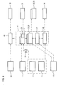
- Fig. 4 shows an overview of the interaction of various devices and information in the motor vehicle 1.
- a night vision camera 24 may be provided to perform the inventive method at night.
- the devices of the motor vehicle 1 must have corresponding interfaces, so that they are accessible via the control device 4 or the night vision control device 46 can be addressed.
- the image or images 21 of the camera 2 are transferred to the track detection device 7, which are evaluated by the latter for the generation of track hypotheses. This can be done directly or indirectly via the control device 4.
- the control device 4 furthermore provides an exit detection device 25, an intersection detection device 26, a position determination device 27 and a POI recognition 28.
- POI refers to "points of interest", which means interesting locations for the driver such as petrol stations, parking lots, museums, hospitals, etc.
- the devices 25 - 28 evaluate data from the navigation device 6.
- the lane hypothesis generating device 29 of the lane detection device 7 determines from the images 21 lane hypotheses, from which the lane detection device 7 selects the most probable lane hypothesis taking into account the information of the devices 25-28.
- the combination of the vehicle equipment makes it possible to satisfy a variety of user needs.
- the night vision camera 24, in particular designed as an infrared camera the information device can achieve night ability 30.
- the track detection device 7 can accomplish an exact track marking 31. With this information, a track-accurate exit marking 32 as well as a lane-specific crossing marking 33 are also possible.
- the POI marking also succeeds with the same accuracy.
- the accurate representation of driving information is in Fig. 5 shown.
- the image 21 of the camera 2 is superimposed in the display device 5, which is located in the dashboard between the speed indicator 35 and the tachometer 36.
- This can be general information such as a speed limit or a truck override prohibition in the form of the symbols 37 and 38, on the other hand can be represented by the inventive method precisely track-accurate information in the form of the navigation arrow 39.
- You can see it in Fig. 5 essentially the lanes 40, 41 and 42 of a three-lane highway. Due to the information from the 3D camera 3, the control device 4 is known that the Lanes 40, 41 and 42 are free at a large distance in front of the motor vehicle 1. This information can be supplemented by indications of the distance sensor 12, if necessary.
- the navigation arrow is located on this lane. This means that the navigation arrow 39 is not just displayed in front of the motor vehicle 1, but that it just gives accurate information. If the distance sensor 12, however, make up motor vehicles on the lane 42, which are slower than the own motor vehicle 1, the navigation arrow is usefully placed on lane 41.
- the navigation arrow 39 For correct perspective representation of the navigation arrow 39 is tapered towards the front area to represent a lying on the lane 42 impression.
- the navigation arrow can also be highlighted with a drop shadow to create a slightly floating impression. Its width should not exceed 2/3 of the lane width, so that even with small errors in the positioning of the navigation arrow 39 is completely displayed lying within a single lane. Otherwise, the presentation could cause irritation to the driver.
- the images of the 3D camera can be further evaluated to the extent that the ground plane in front of the vehicle or its curvature is detected.
- each pixel of an image of the 3D camera is assigned an absolute distance value, from which the curvature of the ground plane can be calculated.
- the control device 4 can also be given a destination track as information.
- maneuver points are known in advance. An approach of the motor vehicle 1 to such a maneuver point can then be displayed with further information.
- the rear end of the navigation arrow 39 is shown slotted and corresponding to the distance to the maneuver point each pieces omitted, so that the driver receives adequate information about the distance to the maneuver point.
- the color of the navigation arrow 39 can also be changed. The color can be changed continuously or in discrete steps.
- the color blue is selected up to a distance of 500 m from the next maneuver point, after which the color changes to green, while it is displayed in red from a distance of less than 150 m to the maneuver point.
- the driver can be given a distance value without the output of numbers on the display device 5.
- the length of navigation arrow 39 can always be selected as a function of road class, a speed-dependent representation is particularly suitable. From the information of the speed sensor 11, for example, a possible minimum braking distance is calculated, which determines the length of the navigation arrow 39. As a result, the driver in the display device 5, a minimum distance to a preceding motor vehicle can be illustrated.
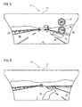
- Fig. 6 shows the representation of a driving instruction at a short distance to a maneuver point.
- the driving information changes from the currently traveled lane according to the route guidance of the navigation device 6 to the destination lane to be traveled shortly in order to display the route to the driver in a concrete and accurate way.
- the driver can also be presented with local information in the form of a location-specific information display, as in FIG Fig. 7 you can see.
- an icon 45 indicating information is assigned to a location in the image 21 by a position indicator in the form of a needle 44.
- the navigation arrow 39 is shown partially erect because it is otherwise poorly perceptible in the present perspective.
- the lane 42 is displayed to the driver early to avoid unnecessary lane changes, for example, from the tracks 41 or 43. This can increase the safety of all road users.
Abstract
Description
Die Erfindung betrifft ein Verfahren zur kombinierten Ausgabe eines Bildes einer Bildaufnahmeeinrichtung und wenigstens einer Fahrinformation an einer Anzeigeeinrichtung eines Kraftfahrzeugs, gemäß dem Oberbegriff des Anspruchs 1.The invention relates to a method for the combined output of an image of an image recording device and at least one driving information on a display device of a motor vehicle, according to the preamble of
Es ist bekannt, Kameras, Infrarotkameras oder andere Bildaufnahmeeinrichtungen an einem Fahrzeug anzuordnen und die durch diese aufgenommenen Bilder in einer Anzeigeeinrichtung innerhalb des Kraftfahrzeugs anzuzeigen. Die Anzeigeeinrichtungen sind im Armaturenbrett oder in der Mittelkonsole des Kraftfahrzeugs angeordnet, grundsätzlich ist aber jede Positionierung im Blickfeld des Fahrers möglich. Die Bilder der Bildaufnahmeeinrichtungen können in der Anzeigeeinrichtung auch mit weiteren Informationen aus Fahrerassistenzsystemen überlagert dargestellt werden. Bei Bedarf kann beispielsweise die aktuelle Geschwindigkeitsbegrenzung oder auch die aktuelle Fahrgeschwindigkeit den Bildern überlagert werden.It is known to arrange cameras, infrared cameras or other image recording devices on a vehicle and to display the images taken by them in a display device within the motor vehicle. The display devices are arranged in the dashboard or in the center console of the motor vehicle, but in principle any positioning in the field of view of the driver is possible. The images of the image recording devices can also be superimposed in the display device with further information from driver assistance systems. If necessary, for example, the current speed limit or the current vehicle speed can be superimposed on the images.
Außerdem ist es bekannt, Fahrhinweise in Form eines Navigationspfeils darzustellen. Um den Fahrer anzuweisen, die aktuelle Fahrrichtung beizubehalten, wird der Navigationspfeil stehend dargestellt, um ein Abbiegen nach Rechts anzuzeigen, wird der Navigationspfeil um 90° im Uhrzeigersinn gedreht. Diese Navigationspfeile können auch den Bildern in der Anzeigeeinrichtung überlagert werden.It is also known to display driving instructions in the form of a navigation arrow. To instruct the driver to maintain the current direction of travel, the navigation arrow is displayed standing to indicate a right turn, the navigation arrow is rotated 90 ° clockwise. These navigation arrows can also be superimposed on the images in the display device.
Weiterhin ist es bekannt, den Fahrer durch Sprachanweisungen von der Zielführung der Navigationseinrichtung zu informieren. Zur Veranlassung eines Fahrmanövers werden die Sprachanweisungen dabei um einen gewissen Zeitabstand vor den Zeitpunkt zur Einleitung des Fahrmanövers nach vorne verlegt, um dem Fahrer einerseits eine angemessene Reaktionszeit zu gewähren und andererseits einen Bezug zur Fahrsituation herzustellen.Furthermore, it is known to inform the driver by voice instructions from the route guidance of the navigation device. To initiate a driving maneuver, the voice instructions thereby become forward a certain time interval before the time for initiating the driving maneuver laid on the one hand to give the driver a reasonable reaction time on the one hand and on the other hand make a reference to the driving situation.
Diese Maßnahmen reichen in den meisten Situationen aus, um eine sichere Zielführung zu gewährleisten. Es gibt allerdings Fahrsituationen, in denen weder die Darstellung der Zielführung als Navigationspfeil noch die Sprachansage eindeutig ist. Als Beispiel seien hier Straßen mit einer Vielzahl an Fahrspuren genannt, wobei nicht klar ist, welcher Spur zu folgen ist. Des Weiteren folgen an Kreisverkehren oft mehrere Abfahrten in kurzen Abständen, so dass auch hier die Zielführung nicht notwendigerweise klar wird. Auch klare Ansagen wie "Bitte verlassen Sie den Kreisverkehr an der dritten Ausfahrt" erfordern ein erhebliches Mitdenken des Fahrers, der gezwungenermaßen die Anzahl der Ausfahrten abzählen muss. Der Fahrer wird daher gerade in kritischen Situationen immer wieder dazu gezwungen, Sprachansagen oder Darstellungen in einer Anzeigeeinrichtung genau zu analysieren und eventuell den Blick lange von der Straße abzuwenden.These measures are sufficient in most situations to ensure safe route guidance. However, there are driving situations in which neither the representation of the route guidance as navigation arrow nor the voice announcement is clear. As an example, here roads with a variety of lanes are called, it is not clear which lane to follow. Furthermore, at roundabouts often follow several departures in short intervals, so that here, the guidance is not necessarily clear. Even clear announcements such as "Please leave the roundabout at the third exit" require a considerable amount of thought from the driver, who is forced to count the number of exits. The driver is therefore constantly forced, especially in critical situations, to analyze voice announcements or presentations in a display device precisely and possibly avert the gaze for a long time from the road.
Ein Verfahren der eingangs genannten Art ist aus
Aus der Druckschrift
Der Erfindung liegt damit die Aufgabe zugrunde, ein Verfahren zur kombinierten Ausgabe eines Bildes und einer Fahrinformation anzugeben, durch das die Zielführung einer Navigationseinrichtung oder auch allgemeine Fahranweisungen bzw. -informationen für den Fahrer leicht aufnehmbar dargestellt werden.The invention is thus based on the object of specifying a method for the combined output of an image and a driving information, by which the route guidance of a navigation device or general driving instructions or information for the driver are displayed easily recordable.
Zur Lösung ist erfindungsgemäß ein Verfahren der eingangs genannten Art vorgesehen, mit den Merkmalen des Kennzeichens des Anspruchs 1.To solve the invention, a method of the type mentioned is provided with the features of the characterizing part of
Erfindungsgemäß ist also vorgesehen, dass der Fahrer in einem Echtzeit-Videobild die von ihm zu befahrende Fahrspur, den vorzunehmenden Fahrspurwechsel oder jede beliebige weitere für das Fahrverhalten wichtige Information angezeigt bekommt. Bei mehrspurigen Straßen kann der Fahrer somit leicht erkennen, welche Fahrspur die zweckmäßigste ist.According to the invention, it is thus provided that the driver in a real-time video image is the lane to be traveled by him, the lane change to be made or any other information important for the driving behavior gets displayed. In multi-lane roads, the driver can thus easily recognize which lane is the most appropriate.
Selbst bei einspurigen Fahrstrecken ist die Anzeige der zu befahrenden Fahrspur durchaus sinnvoll. Gerade für Fahrer, die öfters Aufenthalte in Ländern mit Linksverkehr haben oder auch Urlauber, die mehrere Wochen in einem Land mit Linksverkehr waren, ist es bei Ankunft in einem Land mit Rechtsverkehr durchaus problematisch, sich an die geänderte Fahrsituation anzupassen. Dies gilt umgekehrt selbstverständlich genauso. Hier kann es gerade auf wenig befahrenen Straßen dazu kommen, dass der Fahrer versehentlich die falsche Fahrspur wählt. Sollte einem derart falsch fahrenden Fahrer hinter einer Kurve ein Fahrzeug entgegenkommen, kann es zu einem vermeidbaren Unfall kommen. Erfindungsgemäß kann dem Fahrer also die "richtige" Fahrspur angezeigt werden. Ein einfacher Navigationspfeil bietet diese Information nicht, da er nicht spurgenau angezeigt wird.Even with single-lane routes, the display of the lane to be traveled makes sense. Especially for drivers who often stay in countries with left-hand traffic or vacationers who were several weeks in a country with left-hand traffic, it is quite problematic on arrival in a country with legal traffic to adapt to the changed driving situation. Of course, the same applies in the same way. Here it can happen, especially on roads with little traffic, that the driver accidentally chooses the wrong lane. Should such a wrong-moving driver approach a vehicle behind a bend, an avoidable accident can occur. According to the driver, the "correct" lane can thus be displayed. A simple navigation arrow does not provide this information because it is not displayed accurately.
Mit besonderem Vorteil kann als Information der Navigationseinrichtung wenigstens eine Information über die weitere voraussichtliche, in Segmente aufgeteilte, Fahrstrecke aus der Gruppe Länge des Segments, Anzahl der Fahrspuren, Krümmung der Fahrspuren, Fahrtrichtung der Fahrspuren, Zielspur und aktuelle Position verwendet werden. Neben der aktuellen Position liefert eine Navigationseinrichtung auch sogenannte prädikative Streckendaten, die bei der fahrspurgenauen Zuordnung verwendet werden können.With particular advantage can be used as information of the navigation device at least one information about the further probable, divided into segments, route from the group length of the segment, number of lanes, curvature of the lanes, direction of travel lanes, destination lane and current position. In addition to the current position, a navigation device also supplies so-called predicative route data that can be used in the lane-accurate assignment.
Generell können dabei die Fälle einer aktivierten und einer deaktivierten Zielführung der Navigationseinrichtung unterschieden werden. Ist die Zielführung deaktiviert, wird eine wahrscheinlichste Route von der Navigationseinrichtung berechnet. Selbst bei einspurigen Straßen kann dabei die Anzeige der korrekten Fahrspur hilfreich sein, siehe oben. Bei mehrspurigen Straßen kann dem Fahrer diejenige Spur angezeigt werden, die entlang der Hauptverkehrsrichtung führt. Der Fahrer wird also nicht auf Spuren gelenkt, die ihn im weiteren Verlauf zu einem Abbiegen zwingen würden.In general, the cases of an activated and a deactivated route guidance of the navigation device can be distinguished. If the route guidance is deactivated, a most probable route is calculated by the navigation device. Even on single-lane roads, the display of the correct lane can be helpful, see above. In multi-lane roads, the driver can be shown the lane that leads along the main traffic direction. The driver is therefore not steered on tracks that would force him to turn in the further course.
Bei aktivierter Zielführung der Navigationseinrichtung ist jedoch klar, welche Fahrspur aktuell zu wählen ist. Diese kann dem Fahrer angezeigt werden, wodurch vermehrte Fahrspurwechsel vermieden werden und somit die Fahrsicherheit aller Verkehrsteilnehmer erhöht wird.When the route guidance of the navigation device is activated, however, it is clear which lane is currently to be selected. This can be displayed to the driver, whereby increased lane changes are avoided and thus the driving safety of all road users is increased.
Mit besonderem Vorteil kann als weitere Einrichtung eine Spurerkennungseinrichtung verwendet werden. Die Spurerkennungseinrichtung kann aus dem Bild der Bildaufnahmeeinrichtung oder einem Bild einer weiteren Bildaufnahmeeinrichtung Spurhypothesen ermitteln, und aus den Spurhypothesen unter Verwendung wenigstens einer Information der Navigationseinrichtung die wahrscheinlichste Fahrspur ermitteln. Die Positionsbestimmung durch eine Navigationseinrichtung ist lediglich auf drei bis zwanzig Meter genau. Diese Information reicht daher alleine nicht immer aus, um dem Fahrer spurgenaue Fahrinformationen anzuzeigen. Durch zusätzliches Verwenden einer Spurerkennungseinrichtung kann die Genauigkeit der Positionsbestimmung prinzipiell bis hin zur Auflösung im Bild der Bildaufnahmeeinrichtung hin gesteigert werden. Dies gelingt allerdings nur, wenn die Spurerkennungseinrichtung sowohl die Anzahl wie auch die Lage der Fahrspuren korrekt erkennt. Um die Zuverlässigkeit der Spurerkennungseinrichtung zu erhöhen, ist es daher sinnvoll, prädikative Streckendaten aus der Navigationseinrichtung hinzuzuziehen. Diese werden dazu verwendet, aus den durch die Spurerkennungseinrichtung aufgestellten Spurhypothesen die wahrscheinlichste zu ermitteln. Dadurch kann eine Positionsbestimmung erreicht werden, die die Positionsbestimmung der Navigationseinrichtung deutlich übertrifft.With particular advantage, a track recognition device can be used as a further device. The lane recognition device can determine lane hypotheses from the image of the image recording device or from an image of a further image recording device, and determine the most probable lane from the lane hypotheses using at least one information of the navigation device. The position determination by a navigation device is only accurate to three to twenty meters. Therefore, this information alone is not always sufficient to show the driver accurate driving information. By additionally using a track recognition device, the accuracy of the position determination can in principle be increased up to the resolution in the image of the image recording device. However, this succeeds only if the track recognition device correctly recognizes both the number and the position of the lanes. In order to increase the reliability of the lane recognition device, it therefore makes sense to consult predicative route data from the navigation device. These are used to determine the most likely from the track hypotheses set up by the lane recognition device. As a result, a position determination can be achieved that significantly exceeds the position determination of the navigation device.
Zusätzlich kann als weitere Einrichtung eine 3D-Kamera verwendet werden. Als Information der 3D-Kamera kann wenigstens eine Position und/oder eine Größe und/oder eine Geschwindigkeit eines im 3D-Bild abgebildeten Objekts verwendet werden. Besonders hilfreich ist es beispielsweise zur Positionsbestimmung auf einer mehrspurigen Straße, Objekte auf den seitlichen Fahrspuren zu erkennen. Alternativ ist es auch hilfreich, eine Leitplanke im 3D-Bild extrahieren zu können, sowie deren Abstand zum Kraftfahrzeug. Auch aufgrund dieser Informationen alleine kann die Positionsbestimmung in lateraler Richtung des Kraftfahrzeugs im Vergleich zur Positionsbestimmung mit der Navigationseinrichtung erhöht werden. Aber auch innerorts ist es möglich, durch Erkennung beispielsweise eines Randsteins im 3D-Bild die Positionsbestimmung zu verfeinern.In addition, as a further device, a 3D camera can be used. At least one position and / or a size and / or a speed of an object imaged in the 3D image can be used as information of the 3D camera. It is particularly helpful, for example, to determine the position on a multi-lane road to recognize objects on the side lanes. Alternatively, it is also helpful to be able to extract a guardrail in the 3D image, as well as their distance from the motor vehicle. Also due to this information alone, the position determination in lateral Direction of the motor vehicle can be increased in comparison to the position determination with the navigation device. But even in places it is possible to refine the position by recognizing, for example, a curb in the 3D image.
Alternativ oder zusätzlich kann als weitere Einrichtung ein Lenkwinkelsensor und/oder ein Radwinkelsensor und/oder eine Blinkerbetätigungserfassungseinrichtung und/oder ein Geschwindigkeitssensor und/oder ein Abstandssensor und/oder ein Kompass und/oder eine Verkehrszeichenerkennungseinrichtung des Kraftfahrzeugs verwendet werden. In einer Kurvenfahrt ist beispielsweise der Lenkwinkel bzw. der Radwinkel abhängig von der befahrenen Fahrspur. Somit ist bei Befahren einer Kurve auch eine dieser beiden Informationen ausreichend, um die befahrene Fahrspur zu bestimmen. Ein bevorstehender Fahrspunivechsel kann durch eine Blinkerbetätigungserfassungseinrichtung angezeigt werden. Das Aktivieren des Blinkers wird entweder bei Weiterverfolgen der Fahrtrichtung einen Spurwechsel anzeigen, alternativ kann er auch ein Abbiegen des Kraftfahrzeugs andeuten. Vom Prinzip her ähnlich wie die 3D-Kamera kann auch ein Abstandssensor dazu verwendet werden, Fahrzeuge auf benachbarten Fahrspuren zu detektieren und anhand dieser eine Fahrspurzuordnung vorzunehmen. Selbstverständlich können auch alle vorgehend genannten Informationen zusammen kombiniert werden, um eine möglichst exakte Positionsbestimmung zu erreichen.Alternatively or additionally, as a further device, a steering angle sensor and / or a wheel angle sensor and / or a Blinkerbetätigungserfassungseinrichtung and / or a speed sensor and / or a distance sensor and / or a compass and / or a traffic sign recognition device of the motor vehicle can be used. When cornering, for example, the steering angle or the wheel angle depends on the traffic lane. Thus, when driving on a curve, one of these two pieces of information is sufficient to determine the driving lane. An upcoming lane change may be indicated by a turn signal detection device. Activating the turn signal will either indicate a lane change when following the direction of travel, alternatively it may indicate a turning of the motor vehicle. In principle, similar to the 3D camera, a distance sensor can be used to detect vehicles on adjacent lanes and make a lane assignment based on this. Of course, all information mentioned above can be combined together to achieve the most accurate position determination possible.
Zur Kombination dieser Informationen ist selbstverständlich eine Steuerungseinrichtung mit einer Recheneinrichtung und einer Speichereinrichtung nötig. Um die Kapazität der Recheneinrichtung zu schonen, kann es sinnvoll sein, nach einer einmal vorgenommenen sicheren spurgenauen Positionsbestimmung diese Bestimmung als feststehend anzunehmen, bis eine der genannten Einrichtungen ein Signal aussendet, aufgrund dessen ein möglicher Spurwechsel angenommen werden kann. Beispiele hierfür wären ein Lenkwinkel, der nicht mit dem aufgrund der prädikativen Streckendaten angenommenen Lenkwinkel übereinstimmt bzw. von diesem um mehr als einen gewissen Schwellwert differiert, oder auch eine Betätigung des Blinkers. Bei Vorliegen entsprechender Signale wird also die Steuerungseinrichtung veranlasst, die Positionsbestimmung unter Heranziehung aller möglichen Informationen erneut vorzunehmen. Die Positionsbestimmung kann aber auch ohne Vorliegen bestimmter Aktivierungssignale in kontinuierlichen Zeitabständen vorgenommen werden, um einen von den Fahrerassistenzsystemen unbemerkten Spurwechsel aufzudecken.To combine this information, of course, a control device with a computing device and a memory device is necessary. In order to spare the capacity of the computing device, it may be useful to assume this determination as fixed after a safe and accurate position determination has been carried out once, until one of the devices sends out a signal on the basis of which a possible lane change can be assumed. Examples of this would be a steering angle which does not coincide with the steering angle adopted on the basis of the predicative route data or differs therefrom by more than a certain threshold value, or else an actuation of the turn signal. If corresponding signals are present, then the control device is caused to make the position determination again using all possible information. However, the position determination can also be carried out without the presence of specific activation signals in continuous time intervals in order to discover a lane change unnoticed by the driver assistance systems.
Mit besonderem Vorteil kann als Fahrinformation ein Navigationspfeil angezeigt werden. Damit eine fahrspurgenaue Zuordnung erfolgt, wird der Navigationspfeil als auf der Straße liegend dargestellt. Er kann auch einen Schlagschatten erhalten, so dass er über der Straße schwebend erscheint. Damit der Navigationspfeil als auf der Straße liegend aussieht, muss er perspektivisch richtig, d. h. zum vorderen Ende verjüngt, dargestellt werden.With particular advantage, a navigation arrow can be displayed as driving information. So that a lane-accurate assignment takes place, the navigation arrow is displayed as lying on the road. He may also receive a drop shadow so that he appears hovering across the street. In order for the navigation arrow to look like lying on the road, it must be in perspective correctly, d. H. tapered to the front end, are shown.
Die Breite des Navigationspfeils sollte 2/3 der Fahrspurbreite nicht überschreiten, so dass der Navigationspfeil auch bei geringfügigen lateralen Fehlerwerten vollständig innerhalb der Markierungen einer einzigen Fahrspur angezeigt wird.The width of the navigation arrow should not exceed 2/3 of the lane width, so that the navigation arrow is displayed completely within the markings of a single lane, even with minor lateral error values.
Die Darstellung des Navigationspfeils ist allerdings nicht auf eine Spur beschränkt, sie soll nur spurgenau erfolgen. Beispielsweise ist es bei Ausfahrten sinnvoll, den Navigationspfeil von der vom Fahrzeug befahrenen Fahrspur über eventuell dazwischen liegende Fahrspuren bis hin zur Ausfahrt zu legen, um dem Fahrer eine genaue Fahranweisung bzw. einen konkreten Fahrhinweis zu präsentieren. Dabei soll der Pfeil selbstverständlich von der eigenen Spur exakt auf die Ausfahrt führen, was eine Spurgenauigkeit der Anzeige erfordert. Befindet sich das Kraftfahrzeug beispielsweise auf einer mittleren oder linken Fahrspur einer mehrspurigen deutschen Autobahn, so könnte eine nicht spurgenaue Aufforderung zum Spurwechsel dahingehend missverstanden werden, dass das Auto lediglich auf die rechte Fahrspur zu bewegen ist und nicht auf die Ausfahrt. Derartige Fehlinterpretationen sind erst mit spurgenauen Fahrhinweisen zu vermeiden.However, the representation of the navigation arrow is not limited to one lane, it should only be accurate to the track. For example, it is useful for exits to place the navigation arrow from the lane used by the vehicle over any lanes in between to the exit in order to present the driver with an exact driving instruction or a specific driving instruction. Of course, the arrow should lead exactly from the own lane to the exit, which requires a tracking accuracy of the display. For example, if the motor vehicle is located on a middle or left lane of a multi-lane German motorway, then a lane change request that is not in line with the lane could be misunderstood to the effect that the car is only to be moved to the right lane and not to the exit. Such misinterpretations can only be avoided with accurate driving instructions.
Vorzugsweise kann die Form und/oder die Länge und/oder die Farbe und/oder die Größe und/oder die Transparenz des Navigationspfeils in Abhängigkeit zur Entfernung zu einem Manöverpunkt, an dem das Kraftfahrzeug den eingeschlagenen Fahrweg ändern soll, und/oder in Abhängigkeit der Fahrzeuggeschwindigkeit und/oder der Straßenklasse dargestellt werden. Die Veränderung der genannten Merkmale des Navigationspfeils soll dem Fahrer eine Zusatzinformation bieten, die leicht verständlich ist und für die der Fahrer den Blick nicht länger von der Straße abzuwenden braucht. So kann beispielsweise der Abstand zu einem Manöverpunkt, beispielsweise einer zu verwendenden Ausfahrt auf einer Autobahn, farbkodiert dargestellt werden. In diese Kodierung kann als zusätzliche Information auch eine Information weiterer Sensoreinrichtungen einfließen, beispielsweise eines Geschwindigkeitssensors. Mit den beiden Informationen "Abstand" und "Fahrgeschwindigkeit" wird dann der Navigationspfeil derart farblich kodiert, dass beispielsweise bei einem großen Abstand unabhängig von der Fahrgeschwindigkeit beispielsweise ein Grün- oder Blauton gewählt wird. Mit zunehmender Annäherung an den Manöverpunkt wird der Farbton in einen warnenden oder aggressiven Farbton wie rot oder gelb gewechselt. Denkbar ist es aber auch, den Farbton des Navigationspfeils beständig in einem Grün- oder Blauton zu belassen, solange sich das Kraftfahrzeug mit angepasster Geschwindigkeit auf der durch die Zielführungen bestimmten Fahrroute befindet. Dementsprechend ist es nicht nötig, dem Fahrer Warnhinweise zu geben, solange er einen Wechsel auf die Ausfahrspur noch nicht vornehmen kann. Erst, wenn mittels der Sensoreinrichtungen festgestellt wird, dass sich das Kraftfahrzeug nicht auf die zu benutzende Ausfahrt begibt, soll der Fahrer einen Warnhinweis in Form einer Farbänderung des Navigationspfeils erhalten.Preferably, the shape and / or the length and / or the color and / or the size and / or the transparency of the navigation arrow depending on to remove to a maneuver point at which the motor vehicle is to change the chosen travel path, and / or represented as a function of the vehicle speed and / or the road class. The change of said features of the navigation arrow should provide the driver with additional information that is easy to understand and for which the driver no longer needs to look away from the road. Thus, for example, the distance to a maneuver point, for example, an exit to be used on a highway, color-coded. In this coding can also be used as additional information information of other sensor devices, such as a speed sensor. With the two pieces of information "distance" and "driving speed", the navigation arrow is then color-coded in such a way that, for example, a green or blue tone is selected regardless of the driving speed at a large distance. As you approach the maneuver point, the hue changes to a warning or aggressive hue, such as red or yellow. It is also conceivable, however, to leave the color of the navigation arrow constantly in a green or blue tone, as long as the motor vehicle is at an appropriate speed on the route determined by the guidance guides. Accordingly, it is not necessary to give the driver warnings, as long as he can not make a change to the exit lane yet. Only when it is determined by means of the sensor devices that the motor vehicle does not move to the exit to be used should the driver receive a warning in the form of a color change of the navigation arrow.
Die Länge des Navigationspfeils kann, insbesondere mit der Fahrzeuggeschwindigkeit oder der Straßenklasse korrigiert werden. Beispielsweise kann die Länge stufenweise verändert werden, abhängig von der aktuellen Fahrgeschwindigkeit. Es ist auch möglich, die Länge des Navigationspfeils durch die Steuerungseinrichtung derart berechnen zu lassen, dass für eine vorgegebene Zeitspanne, beispielsweise 2 Sekunden, die bei der vorliegenden Fahrgeschwindigkeit befahrene Strecke bedeckt wird. Als Zeitspanne könnte dabei auch die durchschnittliche Reaktionszeit eines Fahrers gewählt werden, wodurch der Fahrer in der Anzeigeeinrichtung zu sehen bekäme, ob der Abstand zum Vordermann ausreichend für eventuelle Bremsmanöver ist. Dabei könnte zur Berechnung der Länge des Navigationspfeils als Größe auch die Bremskraft des Kraftfahrzeugs eingehen.The length of the navigation arrow can be corrected, in particular with the vehicle speed or the road class. For example, the length can be changed stepwise, depending on the current driving speed. It is also possible to have the length of the navigation arrow calculated by the control device in such a way that, for a predetermined period of time, for example 2 seconds, the distance traveled at the present driving speed is covered. As a time span, the average reaction time of a driver could be selected. whereby the driver would see in the display device, if the distance to the front man is sufficient for any braking maneuvers. In this case, the braking force of the motor vehicle could be used to calculate the length of the navigation arrow as the size.
Alternativ kann der Abstand zu einem Manöverpunkt auch dadurch dargestellt werden, dass der Navigationspfeil zumindest teilweise geschlitzt oder eingekerbt wird. Mit Annäherung an einen Manöverpunkt wird vom hinteren Ende des Navigationspfeils beginnend dieser dann schrittweise verkürzt, womit die Annäherung an den Manöverpunkt visualisiert werden kann.Alternatively, the distance to a maneuver point can also be represented by the navigation arrow being at least partially slotted or scored. Approaching a maneuver point, starting from the rear end of the navigation arrow, it is then gradually shortened, whereby the approach to the maneuver point can be visualized.
Nähert sich das Kraftfahrzeug an eine Kreuzung, bei der es gemäß der Zielführung der Navigationseinrichtung abbiegen muss, wird der Navigationspfeil sinnvollerweise gemäß dem Fahrtweg gerundet dargestellt. Bei kurzem Abstand zu einem derartigen Manöverpunkt ist die Pfeilspitze dann in der Anzeigeeinrichtung oftmals nicht mehr gut auszumachen. Daher wird gemäß einer ersten erfindungsgemäßen Alternative bei Unterschreiten eines Abstands des Kraftfahrzeugs zu einem Manöverpunkt der Navigationspfeil wenigstens teilweise aufgestellt dargestellt. Dadurch bleibt der Navigationspfeil oft bei ungünstigen Darstellungsverhältnissen optimal sichtbar, so dass eine Verwirrung des Fahrers vermieden werden kann.If the motor vehicle approaches an intersection, where it must turn in accordance with the route guidance of the navigation device, the navigation arrow is expediently displayed rounded in accordance with the travel path. At a short distance to such a maneuver point, the arrowhead is then often no longer easy to identify in the display device. Therefore, in accordance with a first alternative according to the invention, when the distance of the motor vehicle from the distance to a maneuvering point is undershot, the navigation arrow is displayed at least partially positioned. As a result, the navigation arrow often remains optimally visible in unfavorable presentation conditions, so that confusion of the driver can be avoided.
Ein weiteres Problem stellen Bodenunebenheiten dar. Normalerweise ist die Kamera parallel zur Bodenfläche, oder sie schließt einen festen Winkel mit ihr ein. Bekannterweise ist die Erdoberfläche allerdings nicht glatt, sondern es gibt auf ihr zahlreiche Erhebungen und Senken. Durch die Bodenunebenheiten kann dann im Bild der Anzeigeeinrichtung der Eindruck entstehen, dass sich der Navigationspfeil in die im Bild dargestellte Bodenebene hineinbohrt oder von ihr abhebt. Um dies zu vermeiden, wird gemäß einer zweiten erfindungsgemäßen Alternative die Darstellung des Navigationspfeils durch wenigstens eine Information einer 3D-Kamera an die in der Anzeigeeinrichtung dargestellte Bodenebene des Bildes der Bildaufnahmeeinrichtung vor dem Kraftfahrzeug angepasst. Dadurch können die oben genannten Darstellungsprobleme vermieden werden und eine Irritation des Fahrers ebenso.Another problem is uneven floors. Normally, the camera is parallel to the floor surface or it includes a fixed angle with it. As is well known, the surface of the earth is not smooth, but there are numerous elevations and depressions on it. Due to the bumps in the image of the display device can give the impression that the navigation arrow drilled into the ground plane shown in the image or stands out from it. In order to avoid this, according to a second alternative according to the invention, the representation of the navigation arrow is adapted by at least one information of a 3D camera to the ground plane of the image of the image recording device in front of the motor vehicle represented in the display device. Thereby, the above-mentioned display problems can be avoided and irritation of the driver as well.
Vorzugsweise kann die Form und/oder die Farbe und/oder die Größe und/oder die Transparenz des Navigationspfeils bei zumindest teilweiser Überlagerung mit einem im Bild der Bildaufnahmeeinrichtung befindlichen Objekt, das keine Fahrbahn oder Fahrspur ist, zumindest teilweise im überlagerten Abschnitt verändert im Vergleich zum nicht überlagerten Abschnitt dargestellt werden. Solche Objekte können andere Kraftfahrzeuge oder auch Häuser sein. Optimalerweise wird die Transparenz des Navigationspfeils genau im vom Objekt überdeckten Bildbereich abgeändert, um das Objekt durch den Navigationspfeil durchscheinen zu lassen. Es ist aber auch denkbar, die Farbe des Navigationspfeils im überschneidenden Bereich zu ändern, um dem Fahrer beispielsweise anzuzeigen, dass sich ein Kraftfahrzeug auf dem von ihm zu befahrenden Weg befindet. Dabei ist dann sinnvollerweise der Warnton rot, während der Rest des Navigationspfeils in der Grundfarbe, beispielsweise grün oder blau, dargestellt wird.Preferably, the shape and / or the color and / or the size and / or the transparency of the navigation arrow at least partially overlapping with an object located in the image of the image pickup device, which is not a lane or lane, at least partially changed in the superimposed section compared to not overlaid section. Such objects may be other motor vehicles or even houses. Optimally, the transparency of the navigation arrow is modified exactly in the image area covered by the object, in order to let the object show through the navigation arrow. However, it is also conceivable to change the color of the navigation arrow in the overlapping area in order to indicate to the driver, for example, that a motor vehicle is in the path to be traveled by it. The warning tone is then usefully red, while the rest of the navigation arrow is displayed in the basic color, for example green or blue.
Daneben betrifft die Erfindung auch ein Kraftfahrzeug, umfassend wenigstens eine Bildaufnahmeeinrichtung, eine Navigationseinrichtung, wenigstens eine weitere Einrichtung zur Informationserfassung, eine Steuerungseinrichtung und eine Anzeigeeinrichtung.In addition, the invention also relates to a motor vehicle, comprising at least one image recording device, a navigation device, at least one further device for information acquisition, a control device and a display device.
Weitere Vorteile, Merkmale und Einzelheiten der Erfindung ergeben sich aus den im folgenden beschriebenen Ausführungsbeispielen sowie anhand der Zeichnungen. Dabei zeigen:
- Fig. 1
- eine Prinzipdarstellung eines erfindungsgemäßen Kraftfahr- zeugs,
- Fig. 2
- eine Spurhypothesenauswahl einer Spurerfassungseinrichtung ohne Berücksichtigung weiterer Informationen,
- Fig. 3
- eine Spurhypothesenauswahl einer Spurerfassungseinrichtung mit Berücksichtigung weiterer Informationen,
- Fig. 4
- eine Prinzipdarstellung des Zusammenwirkens verschiedener Einrichtungen eines Kraftfahrzeugs,
- Fig. 5
- eine Prinzipdarstellung der Ansicht einer Anzeigeeinrichtung einer ersten Ausführungsform,
- Fig. 6
- eine Prinzipdarstellung einer Anzeigeeinrichtung in einer zwei- ten Ausführungsform, und
- Fig. 7
- die Prinzipdarstellung einer Anzeigeeinrichtung in einer dritten Ausführungsform.
- Fig. 1
- a schematic diagram of a motor vehicle according to the invention,
- Fig. 2
- a lane hypothesis selection of a lane detection device without consideration of further information,
- Fig. 3
- a lane hypothesis selection of a lane detection device taking into account further information,
- Fig. 4
- a schematic representation of the interaction of various devices of a motor vehicle,
- Fig. 5
- a schematic representation of the view of a display device of a first embodiment,
- Fig. 6
- a schematic diagram of a display device in a second embodiment, and
- Fig. 7
- the schematic diagram of a display device in a third embodiment.
Das erfindungsgemäße Kraftfahrzeug 1 gemäß
Die Vorteilhaftigkeit der Kombination von Informationen unterschiedlicher Einrichtungen ergibt sich aus den
Abhilfe schafft hier die Verwendung von Informationen weiterer Einrichtungen des Kraftfahrzeugs 1, wie in
Die spurgenaue Darstellung von Fahrinformationen ist in
Zur perspektivisch richtigen Darstellung ist der Navigationspfeil 39 zum vorderen Bereich hin verjüngt, um einen auf der Fahrspur 42 liegenden Eindruck darzustellen. Der Navigationspfeil kann auch mit einem Schlagschatten unterlegt werden, um einen leicht schwebenden Eindruck zu erzeugen. Seine Breite sollte 2/3 der Fahrspurbreite nicht übertreffen, damit auch bei geringen Fehlern in der Positionsbestimmung der Navigationspfeil 39 vollständig innerhalb einer einzigen Fahrspur liegend dargestellt wird. Andernfalls könnte die Darstellung Irritationen beim Fahrer hervorrufen.For correct perspective representation of the
Die Bilder der 3D-Kamera können weitergehend dahin ausgewertet werden, dass die Bodenebene vor dem Kraftfahrzeug bzw. ihre Krümmung erfasst wird. Hierzu wird jedem Bildpunkt eines Bildes der 3D-Kamera ein absoluter Abstandswert zugeordnet, woraus die Krümmung der Bodenebene berechnet werden kann. Mit diesen Informationen kann die Darstellung des Navigationspfeils 39 angepasst werden, da seine Darstellung sich ansonsten bei ungünstigen Verhältnissen in die im Bild 21 dargestellte Bodenebene hineinbohren oder von ihr abheben würde. Auch dies könnte zu Irritationen beim Fahrer führen.The images of the 3D camera can be further evaluated to the extent that the ground plane in front of the vehicle or its curvature is detected. For this purpose, each pixel of an image of the 3D camera is assigned an absolute distance value, from which the curvature of the ground plane can be calculated. With this information, the representation of the
Die in
Ist die Zielführung der Navigationseinrichtung 6 aber aktiviert, kann der Steuerungseinrichtung 4 als Information auch eine Zielspur übergeben werden. In diesem Fall sind auch Manöverpunkte im Voraus bekannt. Ein Annähern des Kraftfahrzeugs 1 an einen solchen Manöverpunkt kann dann mit weiteren Informationen dargestellt werden. Insbesondere ist es denkbar, dass das hintere Ende des Navigationspfeils 39 geschlitzt dargestellt wird und entsprechend der Entfernung zum Manöverpunkt jeweils Stücke wegfallen, so dass der Fahrer eine adäquate Information über den Abstand zum Manöverpunkt erhält. Alternativ oder zusätzlich kann auch die Farbe des Navigationspfeils 39 verändert werden. Die Farbe kann dabei kontinuierlich oder in diskreten Schritten geändert werden. Bis zu einem Abstand von 500 m zum nächsten Manöverpunkt wird beispielsweise die Farbe blau ausgewählt, danach wechselt die Farbe auf grün, während sie ab einer Entfernung von unter 150 m zum Manöverpunkt in rot dargestellt wird. Hierdurch kann ohne die Ausgabe von Zahlen an der Anzeigeeinrichtung 5 dem Fahrer ein Abstandswert vermittelt werden.If the route guidance of the
Die Länge des Navigationspfeils 39 kann zwar grundsätzlich straßenklassenabhängig gewählt werden, allerdings bietet sich insbesondere eine geschwindigkeitsabhängige Darstellung an. Aus den Informationen des Geschwindigkeitssensors 11 wird beispielsweise ein möglicher Mindestbremsweg berechnet, der die Länge des Navigationspfeils 39 bestimmt. Hierdurch kann dem Fahrer in der Anzeigeeinrichtung 5 ein Mindestabstand zu einem vorausfahrenden Kraftfahrzeug verdeutlicht werden.Although the length of
Zusätzlich zu einem Navigationspfeil 39 kann dem Fahrer auch eine Lokalinformation in Form einer ortsgenauen Informationsanzeige dargestellt werden, wie in
Claims (9)
- A method for combined outputting of an image from an image-recording device (2) and at least one piece of driving information (37, 38, 39) on a display device (5) of a motor vehicle (1), wherein the at least one piece of driving information is superimposed on the image by combining pieces of information from a navigation device (6) and from at least one further device, in such a way that the at least one piece of driving information is assigned, with accuracy to the level of a lane, to at least one of the plurality of lanes (40, 41, 42) of the route which is shown in the image, characterized
in that a navigation arrow (39) is displayed as driving information, wherein, when a distance of the motor vehicle from a manoeuvring point is undershot, the navigation arrow is represented in an at least partially upright position, and/or the representation of the navigation arrow is adapted, by at least one piece of information of a 3-D camera (3), to the ground level in front of the motor vehicle in the image of the image-recording device which is represented in the display device. - Method according to Claim 1,
characterized
in that navigation device information which is used comprises at least one piece of information about the further anticipated route, divided into segments, said information being from the group: length of the segment, number of the lanes, curvature of the lanes, direction of travel of the lanes, target lane and current position. - Method according to one of the preceding claims,
characterized
in that a lane-detection device (7) is used as a further device. - Method according to Claim 3,
characterized
in that the lane-detection device determines lane hypotheses from the image of the image-recording device or from an image of a further image-recording device, and in that the most probable lane is determined from the lane hypotheses using at least one piece of information of the navigation device. - Method according to one of the preceding claims,
characterized
in that at least one position and/or one variable and/or one speed of an object which is imaged in the 3-D image is used as information of the 3-D camera. - Method according to one of the preceding claims,
characterized
in that a steering angle sensor (8) and/or a wheel angle sensor (9) and/or a flashing indicator light activation-detection device (10) and/or a speed sensor (11) and/or an inter-vehicle distance sensor (12) and/or a compass (13) and/or a road sign-detection device (14) and/or a yaw rate sensor (47) of the motor vehicle are/is used as a further device. - Method according to one of the preceding claims,
characterized
in that the shape and/or the length and/or the colour and/or the size and/or the transparency of the navigation arrow is represented as a function of the distance from a manoeuvring point at which the motor vehicle is to change the adopted route and/or as a function of the vehicle speed and/or the road class. - Method according to one of the preceding claims,
characterized
in that the shape and/or the colour and/or the size and/or the transparency of the navigation arrow in the case of at least partial superimposition with an object which is located in the image of the image-recording device and which is not a carriageway or a lane, is represented at least partially modified in the superimposed section compared to the non-superimposed section. - Motor vehicle (1), comprising at least one image-recording device (2), one navigation device (6), at least one further device for acquiring information, one control device (4) and one display device (5) for carrying out the method as claimed in one of Claims 1 to 8.
Applications Claiming Priority (2)
| Application Number | Priority Date | Filing Date | Title |
|---|---|---|---|
| DE102008028373A DE102008028373A1 (en) | 2008-06-13 | 2008-06-13 | A method for the combined output of an image and a driving information, and a motor vehicle therefor |
| PCT/EP2009/004297 WO2009149959A1 (en) | 2008-06-13 | 2009-06-15 | Method for combined output of an image and driving information and corresponding motor vehicle |
Publications (2)
| Publication Number | Publication Date |
|---|---|
| EP2289057A1 EP2289057A1 (en) | 2011-03-02 |
| EP2289057B1 true EP2289057B1 (en) | 2011-09-21 |
Family
ID=41168499
Family Applications (1)
| Application Number | Title | Priority Date | Filing Date |
|---|---|---|---|
| EP09761522A Active EP2289057B1 (en) | 2008-06-13 | 2009-06-15 | Method for combined output of an image and driving information and corresponding motor vehicle |
Country Status (4)
| Country | Link |
|---|---|
| EP (1) | EP2289057B1 (en) |
| AT (1) | ATE525715T1 (en) |
| DE (1) | DE102008028373A1 (en) |
| WO (1) | WO2009149959A1 (en) |
Cited By (2)
| Publication number | Priority date | Publication date | Assignee | Title |
|---|---|---|---|---|
| CN103842774A (en) * | 2011-11-02 | 2014-06-04 | 爱信艾达株式会社 | Lane guidance display system, lane guidance display method, and lane guidance display program |
| CN103842775A (en) * | 2011-11-08 | 2014-06-04 | 爱信艾达株式会社 | Lane guidance display system, method, and program |
Families Citing this family (14)
| Publication number | Priority date | Publication date | Assignee | Title |
|---|---|---|---|---|
| DE102010036140A1 (en) * | 2010-09-02 | 2012-03-08 | Daimler Ag | A method of presenting guidelines in a camera-based driver assistance system |
| DE102011010377A1 (en) * | 2011-02-04 | 2012-08-09 | GM Global Technology Operations LLC (n. d. Gesetzen des Staates Delaware) | Method for operating a motor vehicle and motor vehicle |
| DE102011013855A1 (en) | 2011-03-14 | 2012-09-20 | Audi Ag | Method for providing a display and navigation device |
| US20130083061A1 (en) * | 2011-09-30 | 2013-04-04 | GM Global Technology Operations LLC | Front- and rear- seat augmented reality vehicle game system to entertain & educate passengers |
| JP5810842B2 (en) | 2011-11-02 | 2015-11-11 | アイシン・エィ・ダブリュ株式会社 | Lane guidance display system, method and program |
| JP5810843B2 (en) | 2011-11-02 | 2015-11-11 | アイシン・エィ・ダブリュ株式会社 | Lane guidance display system, method and program |
| JP6089506B2 (en) * | 2012-08-31 | 2017-03-08 | アイシン・エィ・ダブリュ株式会社 | Lane guidance display system, method and program |
| KR101480617B1 (en) * | 2013-06-05 | 2015-01-12 | 현대자동차주식회사 | Apparatus and method for processing image signal |
| JP6484228B2 (en) * | 2013-06-13 | 2019-03-13 | モービルアイ ビジョン テクノロジーズ リミテッド | Visually enhanced navigation |
| DE102014213019A1 (en) * | 2014-07-04 | 2016-01-07 | Bayerische Motoren Werke Aktiengesellschaft | Contact analogue display of evasion corridors for vehicles |
| DE102019202589A1 (en) * | 2019-02-26 | 2020-08-27 | Volkswagen Aktiengesellschaft | Method for operating a driver information system in an ego vehicle and driver information system |
| KR20210025767A (en) * | 2019-08-27 | 2021-03-10 | 현대자동차주식회사 | Apparatus for controlling platooning driving, system having the same and method thereof |
| DE102020201242A1 (en) * | 2020-01-31 | 2021-08-05 | Volkswagen Aktiengesellschaft | Method for displaying information as an indication of a subsequent turning of a vehicle at a turning point on a display unit of the vehicle in a contact-analog manner, as well as display device and vehicle |
| CN115235487B (en) * | 2022-08-04 | 2023-11-14 | 北京百度网讯科技有限公司 | Data processing method, device, equipment and medium |
Family Cites Families (3)
| Publication number | Priority date | Publication date | Assignee | Title |
|---|---|---|---|---|
| KR20050081492A (en) * | 2004-02-13 | 2005-08-19 | 디브이에스 코리아 주식회사 | Car navigation device using forward real video and control method therefor |
| DE102004048347A1 (en) * | 2004-10-01 | 2006-04-20 | Daimlerchrysler Ag | Driving assistance device for opposite the field of view of the driver of a motor vehicle positionally correct representation of the further course of the road on a vehicle display |
| JP2007121001A (en) * | 2005-10-26 | 2007-05-17 | Matsushita Electric Ind Co Ltd | Navigation device |
-
2008
- 2008-06-13 DE DE102008028373A patent/DE102008028373A1/en not_active Withdrawn
-
2009
- 2009-06-15 WO PCT/EP2009/004297 patent/WO2009149959A1/en active Application Filing
- 2009-06-15 AT AT09761522T patent/ATE525715T1/en active
- 2009-06-15 EP EP09761522A patent/EP2289057B1/en active Active
Cited By (3)
| Publication number | Priority date | Publication date | Assignee | Title |
|---|---|---|---|---|
| CN103842774A (en) * | 2011-11-02 | 2014-06-04 | 爱信艾达株式会社 | Lane guidance display system, lane guidance display method, and lane guidance display program |
| CN103842775A (en) * | 2011-11-08 | 2014-06-04 | 爱信艾达株式会社 | Lane guidance display system, method, and program |
| CN103842775B (en) * | 2011-11-08 | 2017-07-28 | 爱信艾达株式会社 | Track guiding display system, methods and procedures |
Also Published As
| Publication number | Publication date |
|---|---|
| DE102008028373A1 (en) | 2009-12-24 |
| WO2009149959A1 (en) | 2009-12-17 |
| EP2289057A1 (en) | 2011-03-02 |
| ATE525715T1 (en) | 2011-10-15 |
Similar Documents
| Publication | Publication Date | Title |
|---|---|---|
| EP2289057B1 (en) | Method for combined output of an image and driving information and corresponding motor vehicle | |
| EP2595855B1 (en) | Process to assist a driver of a vehicle | |
| EP2583263B1 (en) | Method for combining a road sign recognition system and a lane detection system of a motor vehicle | |
| EP1303741B2 (en) | Information and control system for vehicles | |
| EP2594461B1 (en) | Method for detecting a parking space for a motor vehicle, parking assistance system and motor vehicle with a parking assistance system | |
| EP2289058B1 (en) | Method for combined output of an image and a piece of local information and corresponding motor vehicle | |
| DE102008049113A1 (en) | Parking process assisting method for motor vehicle, involves projecting target lane computed for parking process and additionally actual-lane, and updating projections in image of camera depending on position of vehicle | |
| DE112018007027T5 (en) | TURNING PATH VISUALIZATION TO IMPROVE SPATIAL AND SITUATIVE AWARENESS DURING TURNING MANEUVERS | |
| DE102005025387A1 (en) | Method and device for driver's warning or to actively intervene in the driving dynamics, if threatening to leave the lane | |
| EP2093738A2 (en) | Method and system for displaying a relevant traffic sign in a vehicle | |
| EP2676857A2 (en) | Method and apparatus for generating a control parameter for a gap assistance system of a vehicle | |
| DE102013211696A1 (en) | Method for completing and / or updating a digital road map, device for a motor vehicle and motor vehicle | |
| DE102014012781B4 (en) | Lane change assistant, associated method of operation and motor vehicle | |
| DE102012017931A1 (en) | Method for assisting driver of motor car during parking process, involves determining whether parking process is permitted, and warning driver of car by acoustic-, optical- and/or haptic signals if parking process is not permitted | |
| EP3318441A1 (en) | Device for supporting a driver of a vehicle with a projection device | |
| EP2505962B1 (en) | Method for operating a navigation device in a vehicle and navigation device | |
| EP1947421B1 (en) | Method for providing turning instructions and navigational device | |
| EP3204889A1 (en) | Method for a motor vehicle provided with a camera, device and system | |
| DE102017212432A1 (en) | Method and device for operating a driver assistance system of a motor vehicle and driver assistance systems | |
| DE102008025707A1 (en) | Traffic routing information determining method for vehicle, involves determining traffic routing information of vehicle from position and time data, which is detected using global positioning system, received from surrounding vehicles | |
| EP4073469A1 (en) | Method for providing a three-dimensional map in a motor vehicle | |
| EP2654027B1 (en) | Method for emitting a warning before an overtaking procedure | |
| DE102014013218A1 (en) | Driver assistance system for a motor vehicle and method for operating such a driver assistance system | |
| DE102017006835A1 (en) | Control system, method and motor vehicle for calculating a motor vehicle trajectory | |
| DE102004036825A1 (en) | Driver assistance system for e.g. vehicle speed control, has sensors recording objects in vehicle surrounding, where system calculates probability of alternative routes based on sensors signal and carries out route preview ahead of vehicle |
Legal Events
| Date | Code | Title | Description |
|---|---|---|---|
| PUAI | Public reference made under article 153(3) epc to a published international application that has entered the european phase |
Free format text: ORIGINAL CODE: 0009012 |
|
| 17P | Request for examination filed |
Effective date: 20110113 |
|
| AK | Designated contracting states |
Kind code of ref document: A1 Designated state(s): AT BE BG CH CY CZ DE DK EE ES FI FR GB GR HR HU IE IS IT LI LT LU LV MC MK MT NL NO PL PT RO SE SI SK TR |
|
| AX | Request for extension of the european patent |
Extension state: AL BA RS |
|
| GRAP | Despatch of communication of intention to grant a patent |
Free format text: ORIGINAL CODE: EPIDOSNIGR1 |
|
| DAX | Request for extension of the european patent (deleted) | ||
| GRAS | Grant fee paid |
Free format text: ORIGINAL CODE: EPIDOSNIGR3 |
|
| GRAA | (expected) grant |
Free format text: ORIGINAL CODE: 0009210 |
|
| AK | Designated contracting states |
Kind code of ref document: B1 Designated state(s): AT BE BG CH CY CZ DE DK EE ES FI FR GB GR HR HU IE IS IT LI LT LU LV MC MK MT NL NO PL PT RO SE SI SK TR |
|
| REG | Reference to a national code |
Ref country code: GB Ref legal event code: FG4D Free format text: NOT ENGLISH |
|
| REG | Reference to a national code |
Ref country code: CH Ref legal event code: EP |
|
| REG | Reference to a national code |
Ref country code: IE Ref legal event code: FG4D Free format text: LANGUAGE OF EP DOCUMENT: GERMAN |
|
| REG | Reference to a national code |
Ref country code: DE Ref legal event code: R096 Ref document number: 502009001409 Country of ref document: DE Effective date: 20111117 |
|
| REG | Reference to a national code |
Ref country code: NL Ref legal event code: VDEP Effective date: 20110921 |
|
| PG25 | Lapsed in a contracting state [announced via postgrant information from national office to epo] |
Ref country code: LT Free format text: LAPSE BECAUSE OF FAILURE TO SUBMIT A TRANSLATION OF THE DESCRIPTION OR TO PAY THE FEE WITHIN THE PRESCRIBED TIME-LIMIT Effective date: 20110921 Ref country code: SE Free format text: LAPSE BECAUSE OF FAILURE TO SUBMIT A TRANSLATION OF THE DESCRIPTION OR TO PAY THE FEE WITHIN THE PRESCRIBED TIME-LIMIT Effective date: 20110921 Ref country code: NO Free format text: LAPSE BECAUSE OF FAILURE TO SUBMIT A TRANSLATION OF THE DESCRIPTION OR TO PAY THE FEE WITHIN THE PRESCRIBED TIME-LIMIT Effective date: 20111221 Ref country code: HR Free format text: LAPSE BECAUSE OF FAILURE TO SUBMIT A TRANSLATION OF THE DESCRIPTION OR TO PAY THE FEE WITHIN THE PRESCRIBED TIME-LIMIT Effective date: 20110921 Ref country code: FI Free format text: LAPSE BECAUSE OF FAILURE TO SUBMIT A TRANSLATION OF THE DESCRIPTION OR TO PAY THE FEE WITHIN THE PRESCRIBED TIME-LIMIT Effective date: 20110921 |
|
| LTIE | Lt: invalidation of european patent or patent extension |
Effective date: 20110921 |
|
| PG25 | Lapsed in a contracting state [announced via postgrant information from national office to epo] |
Ref country code: SI Free format text: LAPSE BECAUSE OF FAILURE TO SUBMIT A TRANSLATION OF THE DESCRIPTION OR TO PAY THE FEE WITHIN THE PRESCRIBED TIME-LIMIT Effective date: 20110921 Ref country code: CY Free format text: LAPSE BECAUSE OF FAILURE TO SUBMIT A TRANSLATION OF THE DESCRIPTION OR TO PAY THE FEE WITHIN THE PRESCRIBED TIME-LIMIT Effective date: 20110921 Ref country code: LV Free format text: LAPSE BECAUSE OF FAILURE TO SUBMIT A TRANSLATION OF THE DESCRIPTION OR TO PAY THE FEE WITHIN THE PRESCRIBED TIME-LIMIT Effective date: 20110921 Ref country code: GR Free format text: LAPSE BECAUSE OF FAILURE TO SUBMIT A TRANSLATION OF THE DESCRIPTION OR TO PAY THE FEE WITHIN THE PRESCRIBED TIME-LIMIT Effective date: 20111222 |
|
| REG | Reference to a national code |
Ref country code: IE Ref legal event code: FD4D |
|
| PG25 | Lapsed in a contracting state [announced via postgrant information from national office to epo] |
Ref country code: CZ Free format text: LAPSE BECAUSE OF FAILURE TO SUBMIT A TRANSLATION OF THE DESCRIPTION OR TO PAY THE FEE WITHIN THE PRESCRIBED TIME-LIMIT Effective date: 20110921 Ref country code: IS Free format text: LAPSE BECAUSE OF FAILURE TO SUBMIT A TRANSLATION OF THE DESCRIPTION OR TO PAY THE FEE WITHIN THE PRESCRIBED TIME-LIMIT Effective date: 20120121 Ref country code: SK Free format text: LAPSE BECAUSE OF FAILURE TO SUBMIT A TRANSLATION OF THE DESCRIPTION OR TO PAY THE FEE WITHIN THE PRESCRIBED TIME-LIMIT Effective date: 20110921 Ref country code: IE Free format text: LAPSE BECAUSE OF FAILURE TO SUBMIT A TRANSLATION OF THE DESCRIPTION OR TO PAY THE FEE WITHIN THE PRESCRIBED TIME-LIMIT Effective date: 20110921 |
|
| PG25 | Lapsed in a contracting state [announced via postgrant information from national office to epo] |
Ref country code: EE Free format text: LAPSE BECAUSE OF FAILURE TO SUBMIT A TRANSLATION OF THE DESCRIPTION OR TO PAY THE FEE WITHIN THE PRESCRIBED TIME-LIMIT Effective date: 20110921 Ref country code: NL Free format text: LAPSE BECAUSE OF FAILURE TO SUBMIT A TRANSLATION OF THE DESCRIPTION OR TO PAY THE FEE WITHIN THE PRESCRIBED TIME-LIMIT Effective date: 20110921 Ref country code: RO Free format text: LAPSE BECAUSE OF FAILURE TO SUBMIT A TRANSLATION OF THE DESCRIPTION OR TO PAY THE FEE WITHIN THE PRESCRIBED TIME-LIMIT Effective date: 20110921 Ref country code: PT Free format text: LAPSE BECAUSE OF FAILURE TO SUBMIT A TRANSLATION OF THE DESCRIPTION OR TO PAY THE FEE WITHIN THE PRESCRIBED TIME-LIMIT Effective date: 20120123 |
|
| PLBE | No opposition filed within time limit |
Free format text: ORIGINAL CODE: 0009261 |
|
| STAA | Information on the status of an ep patent application or granted ep patent |
Free format text: STATUS: NO OPPOSITION FILED WITHIN TIME LIMIT |
|
| PG25 | Lapsed in a contracting state [announced via postgrant information from national office to epo] |
Ref country code: DK Free format text: LAPSE BECAUSE OF FAILURE TO SUBMIT A TRANSLATION OF THE DESCRIPTION OR TO PAY THE FEE WITHIN THE PRESCRIBED TIME-LIMIT Effective date: 20110921 |
|
| 26N | No opposition filed |
Effective date: 20120622 |
|
| REG | Reference to a national code |
Ref country code: DE Ref legal event code: R097 Ref document number: 502009001409 Country of ref document: DE Effective date: 20120622 |
|
| BERE | Be: lapsed |
Owner name: AUDI A.G. Effective date: 20120630 |
|
| PG25 | Lapsed in a contracting state [announced via postgrant information from national office to epo] |
Ref country code: MC Free format text: LAPSE BECAUSE OF NON-PAYMENT OF DUE FEES Effective date: 20120630 |
|
| PG25 | Lapsed in a contracting state [announced via postgrant information from national office to epo] |
Ref country code: MK Free format text: LAPSE BECAUSE OF FAILURE TO SUBMIT A TRANSLATION OF THE DESCRIPTION OR TO PAY THE FEE WITHIN THE PRESCRIBED TIME-LIMIT Effective date: 20110921 |
|
| PG25 | Lapsed in a contracting state [announced via postgrant information from national office to epo] |
Ref country code: BE Free format text: LAPSE BECAUSE OF NON-PAYMENT OF DUE FEES Effective date: 20120630 Ref country code: ES Free format text: LAPSE BECAUSE OF FAILURE TO SUBMIT A TRANSLATION OF THE DESCRIPTION OR TO PAY THE FEE WITHIN THE PRESCRIBED TIME-LIMIT Effective date: 20120101 |
|
| PG25 | Lapsed in a contracting state [announced via postgrant information from national office to epo] |
Ref country code: BG Free format text: LAPSE BECAUSE OF FAILURE TO SUBMIT A TRANSLATION OF THE DESCRIPTION OR TO PAY THE FEE WITHIN THE PRESCRIBED TIME-LIMIT Effective date: 20111221 |
|
| PG25 | Lapsed in a contracting state [announced via postgrant information from national office to epo] |
Ref country code: MT Free format text: LAPSE BECAUSE OF FAILURE TO SUBMIT A TRANSLATION OF THE DESCRIPTION OR TO PAY THE FEE WITHIN THE PRESCRIBED TIME-LIMIT Effective date: 20110921 |
|
| REG | Reference to a national code |
Ref country code: CH Ref legal event code: PL |
|
| PG25 | Lapsed in a contracting state [announced via postgrant information from national office to epo] |
Ref country code: TR Free format text: LAPSE BECAUSE OF FAILURE TO SUBMIT A TRANSLATION OF THE DESCRIPTION OR TO PAY THE FEE WITHIN THE PRESCRIBED TIME-LIMIT Effective date: 20110921 Ref country code: LI Free format text: LAPSE BECAUSE OF NON-PAYMENT OF DUE FEES Effective date: 20130630 Ref country code: CH Free format text: LAPSE BECAUSE OF NON-PAYMENT OF DUE FEES Effective date: 20130630 |
|
| PG25 | Lapsed in a contracting state [announced via postgrant information from national office to epo] |
Ref country code: LU Free format text: LAPSE BECAUSE OF NON-PAYMENT OF DUE FEES Effective date: 20120615 Ref country code: PL Free format text: LAPSE BECAUSE OF FAILURE TO SUBMIT A TRANSLATION OF THE DESCRIPTION OR TO PAY THE FEE WITHIN THE PRESCRIBED TIME-LIMIT Effective date: 20110921 |
|
| PG25 | Lapsed in a contracting state [announced via postgrant information from national office to epo] |
Ref country code: HU Free format text: LAPSE BECAUSE OF FAILURE TO SUBMIT A TRANSLATION OF THE DESCRIPTION OR TO PAY THE FEE WITHIN THE PRESCRIBED TIME-LIMIT Effective date: 20090615 |
|
| REG | Reference to a national code |
Ref country code: AT Ref legal event code: MM01 Ref document number: 525715 Country of ref document: AT Kind code of ref document: T Effective date: 20140615 |
|
| PG25 | Lapsed in a contracting state [announced via postgrant information from national office to epo] |
Ref country code: AT Free format text: LAPSE BECAUSE OF NON-PAYMENT OF DUE FEES Effective date: 20140615 |
|
| REG | Reference to a national code |
Ref country code: FR Ref legal event code: PLFP Year of fee payment: 8 |
|
| REG | Reference to a national code |
Ref country code: FR Ref legal event code: PLFP Year of fee payment: 9 |
|
| REG | Reference to a national code |
Ref country code: FR Ref legal event code: PLFP Year of fee payment: 10 |
|
| P01 | Opt-out of the competence of the unified patent court (upc) registered |
Effective date: 20230529 |
|
| PGFP | Annual fee paid to national office [announced via postgrant information from national office to epo] |
Ref country code: FR Payment date: 20230623 Year of fee payment: 15 Ref country code: DE Payment date: 20230630 Year of fee payment: 15 |
|
| PGFP | Annual fee paid to national office [announced via postgrant information from national office to epo] |
Ref country code: IT Payment date: 20230629 Year of fee payment: 15 Ref country code: GB Payment date: 20230622 Year of fee payment: 15 |