DE10317044A1 - Optical monitoring system for use in maneuvering road vehicles provides virtual guide surfaces to ensure collision free movement - Google Patents
Optical monitoring system for use in maneuvering road vehicles provides virtual guide surfaces to ensure collision free movement Download PDFInfo
- Publication number
- DE10317044A1 DE10317044A1 DE10317044A DE10317044A DE10317044A1 DE 10317044 A1 DE10317044 A1 DE 10317044A1 DE 10317044 A DE10317044 A DE 10317044A DE 10317044 A DE10317044 A DE 10317044A DE 10317044 A1 DE10317044 A1 DE 10317044A1
- Authority
- DE
- Germany
- Prior art keywords
- vehicle
- image data
- driver
- free space
- image
- Prior art date
- Legal status (The legal status is an assumption and is not a legal conclusion. Google has not performed a legal analysis and makes no representation as to the accuracy of the status listed.)
- Withdrawn
Links
- 230000033001 locomotion Effects 0.000 title claims description 27
- 230000003287 optical effect Effects 0.000 title claims description 27
- 238000012544 monitoring process Methods 0.000 title claims description 9
- 238000012545 processing Methods 0.000 claims description 27
- 238000000034 method Methods 0.000 claims description 19
- 230000000694 effects Effects 0.000 claims description 3
- 238000004891 communication Methods 0.000 claims description 2
- 230000002123 temporal effect Effects 0.000 claims description 2
- 230000005540 biological transmission Effects 0.000 claims 1
- 230000000414 obstructive effect Effects 0.000 claims 1
- 238000003672 processing method Methods 0.000 claims 1
- 239000013598 vector Substances 0.000 description 12
- 230000009466 transformation Effects 0.000 description 9
- 230000008901 benefit Effects 0.000 description 4
- 238000006243 chemical reaction Methods 0.000 description 4
- 230000006870 function Effects 0.000 description 4
- 235000004522 Pentaglottis sempervirens Nutrition 0.000 description 3
- 238000003384 imaging method Methods 0.000 description 3
- 240000004050 Pentaglottis sempervirens Species 0.000 description 2
- 239000010261 arctane Substances 0.000 description 2
- 230000006399 behavior Effects 0.000 description 2
- 230000008859 change Effects 0.000 description 2
- 230000006835 compression Effects 0.000 description 2
- 238000007906 compression Methods 0.000 description 2
- 238000013461 design Methods 0.000 description 2
- 238000011156 evaluation Methods 0.000 description 2
- 230000003993 interaction Effects 0.000 description 2
- 238000013507 mapping Methods 0.000 description 2
- 230000000007 visual effect Effects 0.000 description 2
- 238000004422 calculation algorithm Methods 0.000 description 1
- 238000004364 calculation method Methods 0.000 description 1
- 239000003086 colorant Substances 0.000 description 1
- 238000012937 correction Methods 0.000 description 1
- 238000009795 derivation Methods 0.000 description 1
- 238000011161 development Methods 0.000 description 1
- 230000018109 developmental process Effects 0.000 description 1
- 230000007613 environmental effect Effects 0.000 description 1
- 230000004907 flux Effects 0.000 description 1
- 239000000463 material Substances 0.000 description 1
- 230000000284 resting effect Effects 0.000 description 1
- 230000035939 shock Effects 0.000 description 1
- 238000000844 transformation Methods 0.000 description 1
- 238000011179 visual inspection Methods 0.000 description 1
Classifications
-
- B—PERFORMING OPERATIONS; TRANSPORTING
- B60—VEHICLES IN GENERAL
- B60Q—ARRANGEMENT OF SIGNALLING OR LIGHTING DEVICES, THE MOUNTING OR SUPPORTING THEREOF OR CIRCUITS THEREFOR, FOR VEHICLES IN GENERAL
- B60Q9/00—Arrangement or adaptation of signal devices not provided for in one of main groups B60Q1/00 - B60Q7/00, e.g. haptic signalling
- B60Q9/002—Arrangement or adaptation of signal devices not provided for in one of main groups B60Q1/00 - B60Q7/00, e.g. haptic signalling for parking purposes, e.g. for warning the driver that his vehicle has contacted or is about to contact an obstacle
- B60Q9/004—Arrangement or adaptation of signal devices not provided for in one of main groups B60Q1/00 - B60Q7/00, e.g. haptic signalling for parking purposes, e.g. for warning the driver that his vehicle has contacted or is about to contact an obstacle using wave sensors
- B60Q9/005—Arrangement or adaptation of signal devices not provided for in one of main groups B60Q1/00 - B60Q7/00, e.g. haptic signalling for parking purposes, e.g. for warning the driver that his vehicle has contacted or is about to contact an obstacle using wave sensors using a video camera
-
- B—PERFORMING OPERATIONS; TRANSPORTING
- B60—VEHICLES IN GENERAL
- B60R—VEHICLES, VEHICLE FITTINGS, OR VEHICLE PARTS, NOT OTHERWISE PROVIDED FOR
- B60R1/00—Optical viewing arrangements; Real-time viewing arrangements for drivers or passengers using optical image capturing systems, e.g. cameras or video systems specially adapted for use in or on vehicles
- B60R1/20—Real-time viewing arrangements for drivers or passengers using optical image capturing systems, e.g. cameras or video systems specially adapted for use in or on vehicles
- B60R1/22—Real-time viewing arrangements for drivers or passengers using optical image capturing systems, e.g. cameras or video systems specially adapted for use in or on vehicles for viewing an area outside the vehicle, e.g. the exterior of the vehicle
- B60R1/23—Real-time viewing arrangements for drivers or passengers using optical image capturing systems, e.g. cameras or video systems specially adapted for use in or on vehicles for viewing an area outside the vehicle, e.g. the exterior of the vehicle with a predetermined field of view
- B60R1/26—Real-time viewing arrangements for drivers or passengers using optical image capturing systems, e.g. cameras or video systems specially adapted for use in or on vehicles for viewing an area outside the vehicle, e.g. the exterior of the vehicle with a predetermined field of view to the rear of the vehicle
-
- B—PERFORMING OPERATIONS; TRANSPORTING
- B62—LAND VEHICLES FOR TRAVELLING OTHERWISE THAN ON RAILS
- B62D—MOTOR VEHICLES; TRAILERS
- B62D15/00—Steering not otherwise provided for
- B62D15/02—Steering position indicators ; Steering position determination; Steering aids
- B62D15/029—Steering assistants using warnings or proposing actions to the driver without influencing the steering system
- B62D15/0295—Steering assistants using warnings or proposing actions to the driver without influencing the steering system by overlaying a vehicle path based on present steering angle over an image without processing that image
-
- B—PERFORMING OPERATIONS; TRANSPORTING
- B60—VEHICLES IN GENERAL
- B60R—VEHICLES, VEHICLE FITTINGS, OR VEHICLE PARTS, NOT OTHERWISE PROVIDED FOR
- B60R2300/00—Details of viewing arrangements using cameras and displays, specially adapted for use in a vehicle
- B60R2300/30—Details of viewing arrangements using cameras and displays, specially adapted for use in a vehicle characterised by the type of image processing
- B60R2300/304—Details of viewing arrangements using cameras and displays, specially adapted for use in a vehicle characterised by the type of image processing using merged images, e.g. merging camera image with stored images
- B60R2300/305—Details of viewing arrangements using cameras and displays, specially adapted for use in a vehicle characterised by the type of image processing using merged images, e.g. merging camera image with stored images merging camera image with lines or icons
-
- B—PERFORMING OPERATIONS; TRANSPORTING
- B60—VEHICLES IN GENERAL
- B60R—VEHICLES, VEHICLE FITTINGS, OR VEHICLE PARTS, NOT OTHERWISE PROVIDED FOR
- B60R2300/00—Details of viewing arrangements using cameras and displays, specially adapted for use in a vehicle
- B60R2300/30—Details of viewing arrangements using cameras and displays, specially adapted for use in a vehicle characterised by the type of image processing
- B60R2300/307—Details of viewing arrangements using cameras and displays, specially adapted for use in a vehicle characterised by the type of image processing virtually distinguishing relevant parts of a scene from the background of the scene
-
- B—PERFORMING OPERATIONS; TRANSPORTING
- B60—VEHICLES IN GENERAL
- B60R—VEHICLES, VEHICLE FITTINGS, OR VEHICLE PARTS, NOT OTHERWISE PROVIDED FOR
- B60R2300/00—Details of viewing arrangements using cameras and displays, specially adapted for use in a vehicle
- B60R2300/60—Details of viewing arrangements using cameras and displays, specially adapted for use in a vehicle characterised by monitoring and displaying vehicle exterior scenes from a transformed perspective
-
- B—PERFORMING OPERATIONS; TRANSPORTING
- B60—VEHICLES IN GENERAL
- B60R—VEHICLES, VEHICLE FITTINGS, OR VEHICLE PARTS, NOT OTHERWISE PROVIDED FOR
- B60R2300/00—Details of viewing arrangements using cameras and displays, specially adapted for use in a vehicle
- B60R2300/80—Details of viewing arrangements using cameras and displays, specially adapted for use in a vehicle characterised by the intended use of the viewing arrangement
- B60R2300/8086—Details of viewing arrangements using cameras and displays, specially adapted for use in a vehicle characterised by the intended use of the viewing arrangement for vehicle path indication
-
- B—PERFORMING OPERATIONS; TRANSPORTING
- B60—VEHICLES IN GENERAL
- B60R—VEHICLES, VEHICLE FITTINGS, OR VEHICLE PARTS, NOT OTHERWISE PROVIDED FOR
- B60R2300/00—Details of viewing arrangements using cameras and displays, specially adapted for use in a vehicle
- B60R2300/80—Details of viewing arrangements using cameras and displays, specially adapted for use in a vehicle characterised by the intended use of the viewing arrangement
- B60R2300/8093—Details of viewing arrangements using cameras and displays, specially adapted for use in a vehicle characterised by the intended use of the viewing arrangement for obstacle warning
Abstract
Description
Die Erfindung betrifft ein Verfahren und eine Vorrichtung zur Überwachung des Freiraums in Fahrtrichtung eines Fahrzeuges nach den Oberbegriffen der Patentansprüche 1 und 10.The The invention relates to a method and a device for monitoring of the free space in the direction of travel of a vehicle according to the general terms of the claims 1 and 10.
Bei schwierigen Fahrmanövern ist es für Führer von Kraftfahrzeugen oft schwierig abzuschätzen, entlang welcher Bahn sich ihr Fahrzeug bewegen wird und welcher Freiraum zur Kollisionsvermeidung notwendig ist. Dies ist insbesondere dann der Fall, wenn der Fahrzeugführer mit den Abmaßen des Fahrzeugs oder dessen Fahrverhalten nicht vertraut ist.at difficult driving maneuvers is it for leader of motor vehicles often difficult to estimate along which path Your vehicle will move and which space for collision avoidance necessary is. This is especially the case when the driver with the dimensions the vehicle or its handling is unfamiliar.
Um
den Fahrer bei schwierigen Fahrmanövern zu unterstützen, wird
in der japanischen Offenlegungsschrift
Um
dem Fahrzeugführer
einen besseren Überblick über die
tatsächliche
Umgebung des Fahrzeugs und das Zusammenwirken mit diesem zu verschaffen,
wird in der Patentanmeldung ein
Aufgabe der Erfindung ist es deshalb, ein Verfahren und eine Vorrichtung zu finden, welche es dem Führer eines Fahrzeuges ermöglicht den zukünftigen Fahrverlauf seines Fahrzeuges in Bezug auf seine Umgebung zu ersehen und sicher Kollisionsgefahren, durch seitlich oder von oben in den prädizierten Fahrweg hineinragende Teile, zu erkennen.task The invention is therefore a method and an apparatus to find which it the leader a vehicle allows the future Driving course of his vehicle in relation to its environment to see and safe collision hazards, through the side or from the top in the predicted Track protruding parts to recognize.
Die Aufgabe wird durch ein Verfahren und eine Vorrichtung mit den Merkmalen der Patentansprüche 1 und 10 gelöst.The The object is achieved by a method and a device having the features of the claims and 10 solved.
Vorteilhafte Ausgestaltungen und Weiterbildungen der Erfindung sind durch die Unteransprüche beschrieben.advantageous Embodiments and developments of the invention are characterized by the under claims described.
Bei dem Verfahren zur Überwachung des Freiraums in Fahrtrichtung eines Fahrzeuges werden mittels eines Kamerasystems Bilddaten des im Bereich der Fahrtrichtung befindlichen Fahrzeugumfeldes aufgenommen. Zusätzlich wird auf Basis der Betriebsparameter und der Abmessungen des Fahrzeuges innerhalb einer Signalverarbeitungseinheit der für eine ungehinderte Fahrt benötigte dreidimensionale Freiraum voraus berechnet. Dem Führer des Kraftfahrzeuges werden dabei zumindest Teile der durch das Kamerasystem erfassten Bilddaten des benötigten Freiraums auf einer Anzeige angezeigt. In erfinderischer Weise werden die Bilddaten hierbei im wesentlichen aus einer Perspektive angezeigt, wie sich die in Fahrrichtung liegenden Fahrzeugumgebung dem Führer des Fahrzeuges bei direkter Sicht darstellen würde. Desweiteren werden in erfinderischer Weise die dem benötigten Freiraum zugeordneten Bilddaten einer Weiterverarbeitung unterzogen, wobei als ein Ergebnis dieser Weiterverarbeitung, der Fahrzeugführer darüber informiert wird, ob für eine ungehinderte Fahrt ein ausreichender Freiraum zur Verfügung steht oder nicht. In vorteilhafter Weise wird es somit möglich, durch eine kontinuierliche Auswertung der Bilddaten automatisch auch auf eine dynamische Veränderung des Fahrzeugumfeldes zu reagieren und den Fahrzeugführer darüber zu informieren, ob für eine ungehinderte Fahrt ein ausreichender Freiraum zur Verfügung steht oder nicht. Durch die Anzeige zumindest des den benötigten Freiraum darstellenden Teils der Bilddaten hat der Fahrzeugführer die Möglichkeit, selbstständig das Gefahrenpotential im prädizierten Fahrweg abzuschätzen. Die Darstellung der Bilddaten erfolgt hierbei nicht wie in den aus dem Stand der Technik bekannten Systemen in einer perspektivischen Darstellung, welche einer Sicht von oben auf die Szene entspricht (Vogelperspektive), sondern im wesentlichen aus einer Perspektive, wie sich die in Fahrrichtung liegenden Fahrzeugumgebung dem Fahrzeugführer bei direkter Sicht darstellen würde. Hierbei ist es jedoch denkbar, dass das Abbild der Fahrzeugumgebung, insbesondere bedingt durch die Optik des Kamerasystems (beispielsweise Weitwinkeloptik oder katadioptrische Kameraoptik), verzerrt dargestellt wird. Andererseits ist es jedoch auch sehr wohl denkbar, dass im Rahmen der Weiterverarbeitung eine Verzerrung der Bilddaten korrigiert wird. In für ihn eingänglicher Weise sieht der Fahrzeugführer beim Blick auf die Anzeige eine Abbildung der Umgebung, welche perspektivisch im wesentlichen mit derjenigen Ansicht übereinstimmt, die er beim direkten Blick aus dem Fenster selbst wahrnimmt. Es ist entgegen dem aus dem Stand der Technik bekannten also nicht mehr notwendig, dass der Fahrzeugführer die für ihn ungewohnte vogelperspektivische Darstellung in die realen Gegebenheiten umsetzt.In the method for monitoring the free space in the direction of travel of a vehicle, image data of the vehicle surroundings located in the direction of travel are recorded by means of a camera system. In addition, based on the operating parameters and the dimensions of the vehicle within a signal processing unit, the three-dimensional free space required for unrestricted travel is calculated in advance. At least parts of the image data of the required free space captured by the camera system are displayed to the driver of the motor vehicle on a display. In an inventive manner, the image data are displayed here essentially from a perspective of how the driving lying in the direction of travel environment would be the driver of the vehicle in direct view. Furthermore, in an inventive manner, the image data associated with the required free space is subjected to further processing, as a result of this further processing, informing the driver whether sufficient free space is available for unimpeded travel or not. Advantageously, it is thus possible to react automatically by a continuous evaluation of the image data also to a dynamic change of the vehicle environment and to inform the driver about whether or not there is sufficient free space available for unhindered driving. By displaying at least the part of the image data representing the required free space, the driver has the option of independently estimating the danger potential in the predicted driving way. The representation of the image data is not carried out here as in the systems known from the prior art in a perspective view, which corresponds to a view from the top of the scene (bird's eye view), but essentially from a perspective, as the lying in the direction of travel vehicle environment the Driver would represent in direct view. In this case, however, it is conceivable that the image of the vehicle surroundings, in particular due to the optics of the camera system (for example, wide-angle optics or catadioptric camera optics), is distorted. On the other hand, however, it is also very conceivable that a distortion of the image data is corrected in the course of further processing. In his way, the driver looks at the display of a picture of the environment, which in perspective substantially coincides with the view that he perceives when looking directly from the window itself. It is therefore no longer necessary, contrary to what is known from the prior art, that the vehicle driver converts the birds-eye view unfamiliar to him into the real situation.
Die Daten über die Abmaße des Fahrzeugs sind in einem Speicher abgelegt, auf welche die Signalverarbeitungseinheit zugreifen kann, um unter Zuhilfenahme von Betriebsparametern des Fahrzeuges den für das Fahrmanöver benötigten Fahrraum abzuschätzen. Dabei ist es denkbar, dass die im Speicher abgelegten Abmaße nicht mit den tatsächlichen Abmaßen des Fahrzeuges übereinstimmen, sondern um eine gewisse Sicherheitsdistanz erweitert werden. Eine solche Sicherheitsdistanz könnte in vorteilhafter Weise zu 20 Zentimetern angenommen werden. Auch ist es denkbar, diese Sicherheitsdistanz durch die Signalverarbeitungseinheit variabel zu handhaben und je nach Fahrgeschwindigkeit und/oder Gefahrenpotential zu vergrößern oder zu verkleinern. Auch kann die Sicherheitsdistanz für unterschiedliche Bereiche oder Teile des Fahrzeugs unterschiedlich gehandhabt werden. So ist es beispielsweise denkbar, dass der Sicherheitsabstand von Stoßfängern geringer gehalten wird, als dies für die stoßempfindlichen Rückspiegel der Fall ist.The Data about the dimensions of the vehicle are stored in a memory, to which the signal processing unit can access, with the aid of operating parameters of the Vehicle that for the maneuvers required Estimate the driving distance. It is conceivable that the dimensions stored in the memory not with the actual dimensions of the vehicle, but to be extended by a certain safety distance. A such safety distance could be assumed in an advantageous manner to 20 centimeters. Also It is conceivable, this safety distance by the signal processing unit variable to handle and depending on driving speed and / or risk potential to enlarge or to downsize. Also, the safety distance for different Areas or parts of the vehicle are handled differently. For example, it is conceivable that the safety distance of Bumpers lower is held as this for the shock-sensitive rearview mirror the case is.
In erfinderischer Weise wird nun dieser Speicher zur Ablage der Fahrzeugabmessungen so ausgelegt und organisiert, dass darin eine Mehrzahl von Datensätze bezüglich unterschiedlicher Fahrzeugabmessungen abgespeichert sind, welche einzeln, durch gezielte Auswahl selektiert, der Signalverarbeitung zur Verfügung gestellt werden können. Der Speicher kann auch mit einem Mittel versehen sein, durch welches wenigstens einer der im Speicher abgespeicherten Datensätze ausgewechselt werden kann. Dies bietet den Vorteil, dass das System zur Freiraumüberwachung relativ leicht an Veränderungen z.B. der Fahrzeugkonturen (z.B. neuer Anhänger, andere Aufbauten usw.) angepasst werden kann. Gerade eine solche Ausgestaltung ist, vor allem bei Betrieb einer Fahrzeugflotte, insbesondere Lastkraftwagen mit wechselnden Aufbauten von großem Vorteil.In inventive way now this memory for storing the vehicle dimensions designed and organized so that it contains a plurality of records relating to different Vehicle dimensions are stored, which individually, through targeted Selection selected, the signal processing provided can be. The memory may also be provided with a means by which at least one of the stored in the memory records replaced can be. This offers the advantage that the system for clearance monitoring relatively easy to change e.g. vehicle contours (e.g., new trailers, other superstructures, etc.) can be adjusted. Just such an embodiment is, before especially when operating a vehicle fleet, especially trucks with changing bodies of great advantage.
So kann auch elektrotechnisch unversiertes Betriebspersonal über einfache Bedienelemente das erfinderische System bedienen. Dies ohne Austausch von elektronischen Komponenten oder dem Verbinden und Bedienen von Programmiergeräten.So can also electrotechnically unversiertes operating personnel over simple Controls operate the inventive system. This without exchange of electronic components or connecting and operating of Programming devices.
In besonders vorteilhafter Weise lassen sich Änderungen in den Abmaßen des Fahrzeuges besonders einfach in den der Signalverarbeitungseinheit zugeordneten Speicher übernehmen, indem ein neuer die Abmessungen beschreibender Datensatz einfach über eine mobile oder stationäre Datenverarbeitungsanlage über geeignete Schnittstellen in den Speicher eingelesen wird. Besonders vorteilhaft kann bei entsprechender Ausgestaltung des Systems das Einlesen und die Auswahl von Datensätzen auch drahtlos über eine Kommunikationsanlage erfolgen. Im Falle sich häufiger wiederholender (gleicher) Änderungen (z.B. Fahrt mit aufgeladenen, bzw. abgeladenen Container) können auch mehrere unterschiedliche Fahrzeugkonturen oder – abmaße im Speicher der Datenverarbeitungsanlage enthalten sein und abgerufen werden. Insbesondere hierfür kann eine dem Fahrzeugführer zugängliche Tastatur vorgesehen werden. In besonders einfacher und gewinnbringender Weise verfügt diese Tastatur über einzelne den jeweils in dem Speicher abgelegten Datensätzen zugeordnete Tasten, so dass mit einem einzigen gezielten Tastendruck der gewünschte Datensatz ausgewählt werden kann.In Particularly advantageously, changes in the dimensions of the Vehicle particularly easy in the signal processing unit allocate allocated memory, by simply adding a new dataset describing the dimensions via a mobile or stationary Data processing system over suitable interfaces are read into the memory. Especially advantageous can with appropriate design of the system Reading in and selecting records also wirelessly over one Communication system done. In the case of frequently repeated (same) changes (e.g., with loaded or unloaded containers) may also several different vehicle contours or dimensions in the memory of the data processing system be included and retrieved. In particular, this can be a the driver accessible Keyboard be provided. In a particularly simple and profitable way Way this keyboard over individual associated with each stored in the memory records Buttons, so that with a single targeted keystroke the desired record to be selected can.
Nachfolgend wird die Erfindung anhand von Ausführungsbeispielen und mit Hilfe von Figuren im Detail erläutert.The invention will now be described in detail by means of exemplary embodiments and with the aid of figures explained.
Nachdem durch die Signalverarbeitungseinheit der Fahrweg und der hierfür notwendige Freiraum prädiziert wurde, ist es be sonders vorteilhaft, wenn im Rahmend der Weiterverarbeitung der Bilddaten deren dynamische, zeitliche Veränderungen dieser Daten in Betracht gezogen werden. Auf diese Weise kann das System Objekte oder Personen erkennen, welche in den für das Fahrmanöver benötigten Freiraum eindringen. Ist dies der Fall, so sollte in gewinnbringender Weise der Führer des Fahrzeuges darüber informiert werden, dass kein ausreichender Freiraum mehr zur Verfügung steht. Diese Information kann insbesondere durch optisch, akustisch oder haptisch wahrnehmbare Signalgeber erfolgen. Anderseits ist es auch denkbar in den dem Fahrzeugführer angezeigten Bilddaten die den Freiraum behindernden Objekte oder Personen hervorgehoben darzustellen. Hierzu eignet beispielsweise eine farbliche Hervorhebung, insbesondere eine in Bezug auf die Kollisionsgefahr abgestufte Falschfarbdarstellung (beispielsweise: hohe Kollisionsgefahr → Objekt wird rot eingefärbt; geringe Kollisionsgefahr → Objekt wird gelb eingefärbt). In besonders vorteilhafter Weise können die hindernden Objekte oder Personen aber auch dadurch hervorgehoben werden, dass sie durch Symbole überlagert werden. Werden beispielsweise im Rahmen der Weiterverarbeitung der Bilddaten bewegte Objekte mittels eines auf dem Optischen Fluss basierenden Bildverarbeitungsalgorithmus detektiert, so kann in gewinnbringender Weise das bewegte Objekt mit symbolhaften Bewegungsvektoren (Pfeilen) überlagert werden, welche die Bewegungsrichtung und Bewegungsgeschwindigkeit (Länge der Pfeile) beschreiben.After this by the signal processing unit of the infrastructure and the necessary for this Free space predicts was, it is particularly advantageous when in the context of further processing the image data their dynamic, temporal changes of these data into consideration to be pulled. In this way, the system can be objects or people recognize which in the for the driving maneuver required Free space to penetrate. If this is the case then it should be profitable Way the leader of the vehicle above be informed that there is no sufficient free space left. This information can be obtained in particular by optical, acoustic or Haptic perceptible signal generator done. On the other hand it is too conceivable in the driver displayed image data obstructing the free space objects or To highlight people. For example, this is suitable a color highlighting, in particular one relating to the Collision hazard graded false color representation (for example: high risk of collision → object is dyed red; low risk of collision → object turns yellow). In a particularly advantageous manner, the obstructing objects or persons but also be emphasized by that Icons overlaid become. For example, in the context of further processing of Image data moved objects by means of one on the optical flow detected based image processing algorithm, so can in profitably the moving object with symbolic motion vectors (Arrows) superimposed which are the direction of movement and movement speed (Length of the arrows).
Eine besonders vorteilhafte Art und Weise den Fahrzeugführer über den ihm zur Verfügung stehenden Freiraum zu informieren besteht darin, dass im Rahmen der Weiterverarbeitung der Bilddaten die dem Fahrzeugführer angezeigten Bilddaten durch eine symbolische Darstellung der Randbegrenzungen des durch die Vorausberechnung in der Signalverarbeitungseinheit ermittelten, benötigten Freiraums überlagert werden. Hierbei ist es besonders vorteilhaft, die Randbegrenzungen durch symbolisch dargestellte Wände zu beschreiben. Die Höhe der Wände entspricht hierbei der Höhe des benötigten Freiraums (d.h. im wesentlichen den im Speicher abgelegten Abmessungen bezüglich der maximalen Höhe des Fahrzeuges).A particularly advantageous way of informing the driver about the free space available to him is that, as part of the further processing of the image data, the image data displayed to the driver is superimposed by a symbolic representation of the boundary boundaries of the free space determined by the precalculation in the signal processing unit become. It is particularly advantageous to describe the boundary boundaries by symbolically represented walls. The height of the walls in this case corresponds to the height of the required free space (ie essentially the dimensions stored in the memory with respect to the maximum height of the vehicle).
In besonders vorteilhafter Weise, wird die Randbegrenzung so dargestellt, dass der benötigte Freiraum durch eine Art Fahrschlauch begrenzt wird; hierzu wird die Randbegrenzung durch symbolisch dargestellte Wände und einen Deckenbereich in Form eines Tunnels erfolgen. Durch diesen "Tunnelblick" wird die Aufmerksamkeit des Fahrzeugführers gezielt gelenkt, auch kann er wesentlich besser Objekte die seitlich oder von oben in den Freiraum hineinragen besser erkennen.In particularly advantageously, the boundary is shown as that needed Free space is limited by a type of driving tube; this will be the boundary by symbolically represented walls and a ceiling area in the form of a tunnel. Through this "tunnel look" is the attention of the driver Directed, he can also significantly better objects the side or better from the top into the free space.
Für den Fahrer wird die Abschätzung, ob ortsfeste Gegenstände in den rückwärtigen Freiraum hineinragen besonders einfach, wenn er während der (Rückwärts-)fahrt die Relativbewegungen von Gegenständen im Bild vergleichen kann mit der Relativbewegung eines ortsfesten symbolischen Fahrschlauches: bewegen sich die Gegenstände schneller als die Begrenzungen des Fahrschlauches, befinden sie sich räumlich näher – also innerhalb des direkt gefährdeten Bereiches. Bewegen sie sich während der Fahrt langsamer durch das Bild, so sind sie außerhalb des Fahrschlauchs und es besteht keine Gefahr, dass sie bei Weiterfahrt berührt werden. Aus diesem Grund ist es vorteilhaft, Wände und Decke, ggf. sogar den Boden, des symbolisch dargestellten Tunnels so zu gestalten, dass sie
- 1.) eine geometrisch klare und eindeutig identifizierbare Struktur besitzen (beispielsweise: Gitterstruktur, Schachbrettmuster oder Aneinanderreihung von Balken)
- 2.) einen „Durchblick" auf die hinterlegte Videoszene gestatten (beispielsweise: durchbrochene oder halbtransparente Struktur der Wände und/oder der Decke).
- 3.) Aufgrund der Fahrzeugbewegung jeweils so berechnet bzw. bestimmt werden, dass sie in Längsrichtung stillzustehen bleiben.
- 1.) have a geometrically clear and uniquely identifiable structure (for example: grid structure, checkerboard pattern or stringing together of bars)
- 2.) allow a "view" of the deposited video scene (for example: broken or semi-transparent structure of the walls and / or the ceiling).
- 3.) Due to the vehicle movement each calculated or determined so that they remain to rest in the longitudinal direction.
Um
die Überlagerung
des Kamerabildes mit der symbolhaften Beschreibung der Randbegrenzungen des
notwendigen Freiraumes möglichst
realistisch anmuten zu lassen, sind die Abbildungseigenschaften (Transformationsgleichungen)
des Kamerabildes zu beachten. Zum besseren Verständnis, insbesondere bezüglich der
Realisierung der oben unter Punkt
Selbstverständlich ist die Erfindung nicht auf die Verwendung einer solchen Kamera beschränkt, sondern die anhand dieser Kamerageometrie im Detail erläuterten notwendigen Transformationen lassen sich direkt, in einfacher Weise auch auf Kamerasysteme mit anderen Abbildungseigenschaften übertragen.Of course it is the invention is not limited to the use of such a camera, but the necessary transformations explained in detail using this camera geometry can be directly, in a simple way with camera systems render other picture properties.
Koordinatensystemecoordinate systems
Die hier verwendeten Koordinatensysteme folgen den Konventionen aus der Literatur über optischen Fluss. Im 3D-Kamerakoordinatensystem zeigt die Z-Achse in Blickrichtung, die X-Achse nach rechts und die Y-Achse nach unten. Die zentrierten Bildkoordinaten sind gegeben durch eine x-Achse nach rechts und eine x-Achse nach unten. Der Ursprung beider Koordinatensysteme ist die Bildmitte.The Coordinate systems used here follow the conventions the literature about optical flow. In the 3D camera coordinate system shows the Z axis in the viewing direction, the X-axis to the right and the Y-axis to the bottom. The centered image coordinates are given by an x-axis to the right and an x-axis down. The origin of both coordinate systems is the center of the picture.
Von Welt- zu FahrzeugkoordinatenFrom world to vehicle coordinates
Für eine auf
einem bewegten Fahrzeug montierte Kamera kann man zunächst zwei
wichtige Koordinatensysteme einführen:
ein Weltkoordinatensystem, in dem die Fahrzeugumgebung ruht und
ein Fahrzeugkoordinatensystem, dass sich mit dem Fahrzeug bewegt,
siehe ![]()
![]()
Die
momentane Geschwindigkeit des Fahrzeugs ist V = W. Damit ist die
zeitliche Ableitung eines Punktes, der in der Fahrzeugumgebung ruht: ![]()
![]()
Von Fahrzeug- zu KamerakoordinatenFrom vehicle to camera coordinates
In 
Im allgemeinen Fall enthält diese Transformation nicht nur den Neigewinkel τ, sondern die drei Eulerwinkel.in the general case contains this transformation not only the tilt angle τ, but the three Euler angles.
Aus
Gl. 2 folgt die Bewegung eines stationären Punktes in Kamerakoordinaten
Polare KamerakoordinatenPolar camera coordinates
Die arctan(y, x)-Funktion mit zwei Argumenten bestimmt die Phase der komplexen Zahl x + iy im Wertebereich ] – π, π]. Die Reihenfolge der Argumente wurde nach dem Vorbild der ANSI-C-Funktion atan2 gewählt.The arctan (y, x) function with two arguments determines the phase of the complex number x + iy in the range of values] - π, π]. The order of the arguments was chosen on the model of the ANSI-C function atan2.
Umwandlung
von Polar- in cartesische Koordinaten:
Umwandlung
von cartesischen in Polarkoordinaten: ![]()
![]()
Polare BildkoordinatenPolar image coordinates
Umwandlung
von Polar- in cartesische Koordinaten:
Umwandlung
von cartesischen in Polarkoordinaten: ![]()
![]()
Schnittpunkte der Sichtstrahlen mit Ebenen im ObjektraumIntersections of the visual rays with layers in object space
Ein
Sichtstrahlvekior w sei gegeben in Fahrzeugkoordinaten. Falls w1 ≠ 0,
schneidet der Strahl die Ebene XV = a im
Punkt ![]()
![]()
Falls
w2 ≠ 0,
schneidet der Strahl die Ebene YV = b im
Punkt ![]()
![]()
Falls
w3 ≠ 0,
schneidet der Strahl die Ebene ZV = c im
Punkt ![]()
![]()
Omnicam-AbbildungOmnicam imaging
Spiegelformmirror shape
Die Abbildung durch die hier modellierte Omnicam erfolgt in zwei Schritten: Eine Reflexion an einem parabolischen Spiegel gefolgt von einer orthographischen Abbildung.The Illustration by the modeled Omnicam takes place in two steps: A reflection on a parabolic mirror followed by a orthographic illustration.
Die paraboloide Spiegeloberfläche mit einer Brennweite f ist gegeben durchThe Paraboloid mirror surface with a focal length f is given by
![]()
![]()
Dieser
Ausdruck wird in vielen folgenden Gleichungen verwendet. D.h. dort
steht z für
den Term auf der rechten Seite der Gleichung, der von der Bildposition
(x, y) abhängt.
Da der Fokus der Paraboloids im Koordinatenursprung ist, ist die
Blickrichtung am Bilduunkt (x, y) gegeben durch ![]()
![]()
Die
Ableitung der Paraboloid-Gleichung (21) ist 
D.h.,
ein Normalenvektor auf die Spiegeloberfläche hat die Richtung ![]()
![]()
Dabei wird nicht gefordert, dass s(x, y) oder m(x, y) Einheitsvektoren sind.there it is not required that s (x, y) or m (x, y) be unit vectors are.
Projektion von PunktenProjection of points
Die
Omnicam-Abbildung ist am einfachsten darstellbar in Polarkoordinaten: ![]()
![]()
Wie
oben eingeführt,
ist r der Abstand von der Bildmitte. gemessen in Pixeln. θ ist die
Neigung der Blickrichtung zur optischen Achse. Diese Beziehung kann
mithilfe von
In
cartesischen Koordinaten lautet dies 
Projektion von Geradenprojection from straight lines
Eine Gerade im Raum ist gegeben durch einen Punkt p und eine Richtung l = (l1, l2, l3)t mit ∣l∣ = 1. Der Vektor n = p × l ist senkrecht auf der Ebene, die durch die Gerade und den Ursprung der Kamerakoordinaten aufgespannt wird. Die Komponenten von n bestimmen die Art des Omnicam-Bildes der 3D-Geraden:A line in space is given by a point p and a direction l = (l 1 , l 2 , l 3 ) t with ||l| = 1. The vector n = p × l is perpendicular to the plane passing through the line and the origin of the camera coordinates is spanned. The components of n determine the type of omnicam image of the 3D line:
-
– Falls
n = 0, schneidet die Gerade den Ursprung und ihr Bild ist ein Punkt
mit den Koordinaten - If n = 0, the line intersects the origin and its image is a point with the coordinates

-
– Falls
n ≠ 0, aber
n3 = 0, ist die 3D-Gerade parallel zur optischen
Achse und ihr Bild ist eine 2D-Gerade durch die Bildmitte mit der
Gleichung
-
– Andernfalls
ist das Bild der Geraden ein Kreisbogen mit Mittelpunkt (xc, yc) und Radius
r:
Abstand von EbenenDistance from levels
Die
Länge des
Vektors s(x, y) aus Gl. (22) ist ![]()
![]()
Daher
hat ein Punkt in der Entfernung R mit der Bildposition (x, y) die
Kamera-![]()
![]()
Dies
ergibt eine kompakte Beziehung zwischen den Kamerakoordinaten eines
Objektpunktes einerseits sowie Abstand R und Bildposition (x, y)
andererseits: 
![]()
![]()
Der
Abstand einer senkrechten Wand mit der Gl. X = a ist so für einen
Bildpunkt x, y gegeben durch![]()
![]()
![]()
![]()
Falls
a < 0 ist die Wand
nur auf der linken Bildseite (x < 0)
sichtbar und umgekehrt. Eine horizontale Ebene hat die Gleichung
YV = b im Weltkoordinatensystem. Mit Gl.
(4) kann man dies in Kamerakoordinaten transformieren:
Eingesetzt
in Gl. (38): ![]()
![]()
![]()
![]()
Falls b > 0, ist die Ebene nur unterhalb des Horizonts sichtbar.If b> 0, is the level only visible below the horizon.
Rektifikation von Omnicam-BildernRectification of Omnicam images
Für Omnicams
mit einem effektiven Projektionspunkt kann aus dem Omnicam-Bild
eine Lochkameraansicht rekonstruiert werden. [1] Die zentrierten
Lochkamerakoordinaten sind gegeben durch die Projektionsgleichung 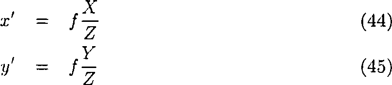
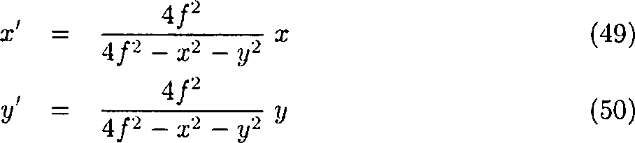
Die
Beziehung zwischen den Omnicam- und Lochkamerakoordinaten sind gegeben
durch eine Kompressionsfunktion, die man aus Gl. (27f) ableiten
kann: ![]()
![]()
Einen
Graphen dieser Kompressionsfunktion zeigt
Die
Omnicam-Bildposition (x, y) entspricht den zentrierten Lochkamerakoordinaten
(X', y') gemäß 
Die inverse Transformation istThe is inverse transformation
Einen
Graph dieses Koeffizienten 4/(4 – ρ2) zeigt
Horizont und FOEHorizon and FOE
Zur
Beschreibung der Effekte der Fahrzeugbewegung im Bild ist benutzt
man die Begriffe Horizont, und Expansionspunkt (oder FOE von engl.
focus of expansion).
Eine Gerade in der Horizontebene ist gegeben durch einen Punkt pV = (0, 0, 1)t und die Richtung lV = (1, 0, 0)t. Eine Normale auf der Horizontebene ist nV = (0, 1, 0)t, und hat die Kamerakoordinaten n = (0, cosτ, sinτ)t. Wie oben diskutiert, muss man zwei Fälle unterscheiden
- – Für Kameraneigung τ = 0 ist der Horizont eine Gerade mit y = 0.
- – Für τ ≠ 0 ist der
Horizont ein Kreisbogen, dessen Mittelpunkt und Radius gegeben sind
durch
- - For camera tilt τ = 0, the horizon is a straight line with y = 0.
- - For τ ≠ 0, the horizon is a circular arc whose center and radius are given by
Für die in
Die
Ordinate ergibt sich für τ ≠ 0 ![]()
![]()
Bei
einer symbolischen Darstellung des Fahrraums durch ein Gittermuster
bestehen nun gerade die Gitterelemente aus senkrechten und waagerechten
Abschnitte von Geraden pi, li,
gemäß der Erläuterung
zu den Gleichungen (29) bis (34), wobei die pi jeweils
Aufpunkte auf den Geradenabschnitten und li jeweils
einen von zwei Einheitsvektoren in Richtung der entsprechenden Gitterelemente
darstellt. Diese Geradenabschnitte werden wie angegeben in Kreisabschnitte
auf der Bildsensorfläche
transformiert und diese als Gittermuster dargestellt. Die ortsfeste
Darstellung der symbolischen Gitterelemente wird nun dadurch bewerkstelligt,
dass bei einer – etwa
durch einen Drehgeber am Rad gemessene – Fahrt um die Strecke s in
Längsrichtung
des Fahrzeugs alle Aufpunkte li um die Strecke
s entgegen der Fahrtrichtung verschoben werden.
Weiterhin ist es sinnvoll, dass der Fahrer sein Fahrzeug nicht unbedingt dauernd bewegen muss, um auf die beschriebene Weise anhand der Bewegungsmuster im Bild die Gefährdung von Objekten zu bestimmen. Es sollte ihm deshalb ermöglicht werden, z.B. durch Betätigung einer Taste eine Wiederholung der letzten Bewegungssequenz auf dem Anzeigesystem zu generieren. Dieses kann z.B. das Bildmaterial der letzten 5m Fahrstrecke mit eingeblendetem Fahrschlauch, dargestellt in einer Endlosschleife sein.Farther It makes sense that the driver does not necessarily keep his vehicle permanently must move in the manner described using the movement pattern in the picture the danger of objects. It should therefore be possible for him e.g. by operation a repeat of the last motion sequence on the button Generate display system. This may e.g. the footage of last 5m driving distance with inserted driving tube, shown be in an infinite loop.
Mögliche Gestaltungselemente des symbolischen Fahrschlauchs, welche die im letzten Abschnitt beschriebenen Bedingungen der klaren geometrischen Struktur und der Transparenz erfüllen sind z.B. die Darstellung der Randbegrenzung mittels eines Gittermusters, einer Aneinanderreihung von Balken oder eines Schachbrettmusters.Possible design elements of the symbolic driving tube, which is the one in the last section described conditions of clear geometric structure and fulfill the transparency are e.g. the representation of the boundary by means of a grid pattern, a sequence of bars or a checkerboard pattern.
Ohne
die Überlagerung
der Bilddaten mit den symbolischen Wänden
Durch
die in den dargestellten Beispielen verwendete klare geometrische
Struktur des symbolischen Fahrschlauchs wird in Verbindung mit einer
verzeichnenden Optik, etwa einem katadioptrischen Objektiv ein weiterer
Vorteil erzielt: durch die Referenzstruktur des auf die gleiche
Art verzeichneten symbolischen Fahrschlauches fällt es dem Fahrer wesentlich
leichter, die Verzeichnungen des Objektivs unbewusst abzuschätzen und
zu berücksichtigen.
Besonders deutlich wird dieses in den
In besonders vorteilhafter Weise eignet sich die Erfindung zur Rückraumüberwachung beim Rangierbetrieb eines Kraftfahrzeuges. Hierbei ist der rückwärtige Raum für den Fahrzeugführer oft nicht direkt einsehbar, so dass er auf eine besonders eingängige Darstellung der Umgebung und der Interaktion seines Fahrzeuges darin angewiesen ist.In Particularly advantageously, the invention is suitable for monitoring the back room when maneuvering a motor vehicle. Here is the back space for the driver Often not directly viewable, giving it a particularly catchy appearance depending on the environment and the interaction of his vehicle therein is.
Eine
weitere Unterstützung
und Entlastung des Fahrers beim Rangieren kann erreicht werden,
wenn ihm der oben beschriebene Vergleich der Bewegung eines ortsfesten
Fahrschlauches mit der tatsächlichen Bewegung
von Gegenständen
im Bild nicht mehr anhand des Augenscheins überlassen, sondern von einer Berechnungseinheit
selbständig
vorgenommen wird. Dieses ist möglich
mit der Anwendung von z.B. der Robotik bekannten Verfahren des Vergleichs
des gemessenen optischen Flusses im Bild mit dem errechneten optischen
Flusses eines Modellvektorfeldes, hier dem Modell eines geometrisch
definierten Fahrschlauches entsprechend
Die für die automatische Auswertung und den Vergleich des optischen Flusses notwendige Algorithmik ist nachstehend beispielhaft für die Verwendung eines Kamerasystems bestehend aus einer kathadioptrischen Kamera (Omnicam) mit einem parabolischen Spiegel beschrieben. Selbstverständlich lassen sich diese Grundlagen entsprechend auch auf andere Kamerasysteme mit anderen optischen Eigenschaften übertragen.The for the automatic evaluation and comparison of the optical flow necessary algorithmics are exemplary of use below a camera system consisting of a cathadioptric camera (Omnicam) with a parabolic mirror. Of course, let These basics also apply to other camera systems transmitted with other optical properties.
Optischer FlussOptical flow
Allgemeiner optischer FlussGeneral optical River
The
derivative of the Omnicam projection equations Die Zeitableitung
der Omnicam-Abbildungsgleichungen
(27f) ist 
Setzt
man die Abbildungsgleichungen (27f) wieder ein, ergibt sich 
Optischer Fluss bei geneigter KameraOptical flow at more inclined camera
Für eine geneigte
Kamera wie in 
Dabei
beachte man, dass R und z von der Bildposition abhängen. Ausführlicher
lautet daher der vertikale Fluss ![]()
![]()
Der Abstand R(x, y) moduliert den horizontalen und vertikalen Fluss mit demselben Vorfaktor. Daher beeinflusst R(x, y) nur die Länge der Flussvektoren, nicht aber deren Richtung. Wie gezeigt, wird die Flussrichtung nur durch die Kamerabewegung bestimmt, d.h. durch die Lage des Expansionspunktes. Für diese Translationsbewegung ist die Richtung der Flussvektoren also unabhängig von der Tiefenstruktur der Umgebung.Of the Distance R (x, y) modulates the horizontal and vertical flow with the same factor. Therefore, R (x, y) only affects the length of the Flow vectors, but not their direction. As shown, the Flow direction determined only by the camera movement, i. by the location of the expansion point. For this translational movement the direction of the flow vectors is therefore independent of the depth structure the environment.
Optische Fluss bei Kamera in FahrtrichtungOptical flow at camera in the direction of travel
Für eine Omnicam,
deren Achse in Fahrtrichtung zeigt, vereinfachen sich die Flussgleichungen
(60f): 
Dies ist dem Flussfeld der Lochkamera sehr ähnlich. Der einzige Unterschied besteht im Nenner R, bei der Lochkamera steht dort Z. Bei beiden Kameratypen ist das Flussfeld in diesem Fall rein radial, d.h. der Flussvektor (x, j) ist parallel zum Radiusvektor (x, y), auch wenn sich R(x, y) über das Bild ändert.This is very similar to the flow field of the pinhole camera. The only difference exists in the denominator R, in the pinhole camera there is Z. In both Camera types is the flow field in this case purely radial, i. the river vector (x, j) is parallel to the radius vector (x, y), even if R (x, y) over the picture changes.
Für eine frontoparallele
Wand bei der Tiefe Z = c folgt aus Gl. (38) ![]()
![]()
Daher
sieht das zugehörige
Flussfeld aus wie in 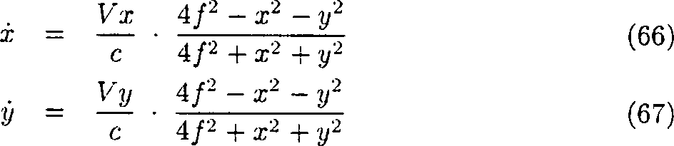
Optischer Fluss einer vertikalen SeitenwandOptical flow of a vertical side wall
Man
betrachte nun wieder eine Kamera mit Neigungswinkel τ am Fahrzeug
wie in 
Ausführlicherlicher
lautet dies so: 
Dies
ist in
Optischer Fluss einer horizontalen EbeneOptical flow of a horizontal plane
Eine
horizontale Ebene (z.B. die Straße oder ein Garagendach) ist
gegeben durch YV = b. Die Wandentfernung
nach Gl. (42) kann man in die allgemeine Flussgleichung (60f) einsetzen: 
Ausführlicherlicher
lautet dies so: 
Dies
ist in
Zur
Vereinfachung kann man noch die dritte binomische Formel anwenden: 
Optischer Fluss eines KorridorsOptical flow of a corridor
Diejenigen Stellen im Bild, an denen der Modellfluss geringer ist, als der tatsächlich gemessene Fluss, sind potentielle Kollisionskandidaten und werden als solche dem Fahrer in einer auffälligen Farbe dargestellt und können bei entsprechender Größe auch zur Generierung eines beispielsweise akustischen Warnsignals herangezogen werden.Those Positions in the picture where the model flow is less than that indeed measured flow, potential collision candidates and are as such, presented to the driver in a flashy color and can with appropriate size too for generating an example acoustic warning signal used become.
Claims (21)
Priority Applications (3)
| Application Number | Priority Date | Filing Date | Title |
|---|---|---|---|
| DE10317044A DE10317044A1 (en) | 2003-04-11 | 2003-04-11 | Optical monitoring system for use in maneuvering road vehicles provides virtual guide surfaces to ensure collision free movement |
| EP04007890A EP1470958B1 (en) | 2003-04-11 | 2004-04-01 | Monitoring of a free space for motor vehicles |
| US10/822,513 US7136754B2 (en) | 2003-04-11 | 2004-04-12 | Free space monitoring system for motor vehicles |
Applications Claiming Priority (1)
| Application Number | Priority Date | Filing Date | Title |
|---|---|---|---|
| DE10317044A DE10317044A1 (en) | 2003-04-11 | 2003-04-11 | Optical monitoring system for use in maneuvering road vehicles provides virtual guide surfaces to ensure collision free movement |
Publications (1)
| Publication Number | Publication Date |
|---|---|
| DE10317044A1 true DE10317044A1 (en) | 2004-10-21 |
Family
ID=32946377
Family Applications (1)
| Application Number | Title | Priority Date | Filing Date |
|---|---|---|---|
| DE10317044A Withdrawn DE10317044A1 (en) | 2003-04-11 | 2003-04-11 | Optical monitoring system for use in maneuvering road vehicles provides virtual guide surfaces to ensure collision free movement |
Country Status (3)
| Country | Link |
|---|---|
| US (1) | US7136754B2 (en) |
| EP (1) | EP1470958B1 (en) |
| DE (1) | DE10317044A1 (en) |
Cited By (10)
| Publication number | Priority date | Publication date | Assignee | Title |
|---|---|---|---|---|
| DE102005051804A1 (en) * | 2005-10-27 | 2007-05-03 | Daimlerchrysler Ag | Driver assistance system for reversing or articulated vehicle has on board display indicating path lines |
| FR2942064A1 (en) * | 2009-02-10 | 2010-08-13 | Peugeot Citroen Automobiles Sa | Method for alerting driver of motor vehicle e.g. bus, during event occurred on back side of vehicle, involves displaying pictogram in form of contour of visible part of reflection of vehicle on glass of rear-view mirrors |
| DE102009053807A1 (en) * | 2009-11-18 | 2011-05-19 | Conti Temic Microelectronic Gmbh | A method of assisting a driver when parking a vehicle |
| DE102014203353A1 (en) * | 2014-02-25 | 2015-08-27 | Volkswagen Aktiengesellschaft | A method of assisting a driver in the passage of a track constriction and driver assistance system therefor |
| DE102016216567A1 (en) | 2016-09-01 | 2018-03-01 | Bayerische Motoren Werke Aktiengesellschaft | A method, apparatus, computer program and computer program product for detecting a constriction of a travel path of a vehicle |
| DE102017221191A1 (en) * | 2017-11-27 | 2019-05-29 | Volkswagen Aktiengesellschaft | Method for displaying the course of a safety zone in front of a vehicle or an object with a display unit, device for carrying out the method and motor vehicle and computer program |
| DE102018127061B3 (en) * | 2018-10-30 | 2019-11-14 | Daimler Ag | Method for operating an assistance system of a vehicle, device for carrying out the method and vehicle |
| DE102018209334A1 (en) * | 2018-06-12 | 2019-12-12 | Robert Bosch Gmbh | Method of visualization |
| WO2021043732A1 (en) | 2019-09-05 | 2021-03-11 | Valeo Schalter Und Sensoren Gmbh | Display of a vehicle environment for moving the vehicle to a target position |
| US11661722B2 (en) | 2020-11-19 | 2023-05-30 | Deere & Company | System and method for customized visualization of the surroundings of self-propelled work vehicles |
Families Citing this family (93)
| Publication number | Priority date | Publication date | Assignee | Title |
|---|---|---|---|---|
| US20050206225A1 (en) * | 2004-03-18 | 2005-09-22 | Ford Global Technologies, Llc | Method and apparatus for predicting the position of a trailer relative to a vehicle |
| DE102005004394B4 (en) * | 2005-01-31 | 2012-09-06 | Continental Automotive Gmbh | Return assistant |
| DE102005018408A1 (en) * | 2005-04-20 | 2006-10-26 | Valeo Schalter Und Sensoren Gmbh | Method and device for evaluating distance measuring data of a distance measuring system of a motor vehicle |
| EP1717757A1 (en) * | 2005-04-28 | 2006-11-02 | Bayerische Motoren Werke Aktiengesellschaft | Method for graphically displaying the surroundings of a motor vehicle |
| DE102005062151B4 (en) * | 2005-12-22 | 2007-09-13 | Daimlerchrysler Ag | Method and device for assisting a driver in the passage of constrictions |
| DE102006008981A1 (en) * | 2006-02-23 | 2007-08-30 | Siemens Ag | Driver assistance system for motor vehicle, has determination unit that combines data with signals from channels during detection of objects/situation by sensors and video sources with respect to control/influence of interface module |
| FR2913798B1 (en) * | 2007-03-16 | 2011-09-02 | Valeo Vision | METHOD FOR DETERMINING THE PASSAGE OF A VEHICLE IN A GOULET |
| EP1892688B1 (en) | 2006-08-24 | 2010-09-01 | Valeo Vision | Method for determining the passing of a vehicle in a bottleneck |
| DE102006041651A1 (en) * | 2006-08-24 | 2008-03-13 | Valeo Schalter Und Sensoren Gmbh | Motor vehicle ability determining method for use in e.g. parking space, in roadway, involves detecting restricted gap in roadway, and defining vehicle image of vehicle, and comparing vehicle image with restricted gap |
| DE102006047131A1 (en) | 2006-10-05 | 2008-04-10 | Robert Bosch Gmbh | Method for automatically controlling a vehicle |
| GB2447672B (en) | 2007-03-21 | 2011-12-14 | Ford Global Tech Llc | Vehicle manoeuvring aids |
| US8233045B2 (en) * | 2007-07-16 | 2012-07-31 | Trw Automotive U.S. Llc | Method and apparatus for distortion correction and image enhancing of a vehicle rear viewing system |
| DE102008044073A1 (en) | 2008-11-26 | 2010-05-27 | Robert Bosch Gmbh | Control device for parking assistance |
| US8493409B2 (en) * | 2009-08-18 | 2013-07-23 | Behavioral Recognition Systems, Inc. | Visualizing and updating sequences and segments in a video surveillance system |
| JP5035643B2 (en) * | 2010-03-18 | 2012-09-26 | アイシン精機株式会社 | Image display device |
| US9230419B2 (en) | 2010-07-27 | 2016-01-05 | Rite-Hite Holding Corporation | Methods and apparatus to detect and warn proximate entities of interest |
| DE102010064277B4 (en) | 2010-12-28 | 2024-03-14 | Robert Bosch Gmbh | Safety feature in a driver assistance system with a rear view camera |
| DE102011013774A1 (en) | 2011-03-12 | 2012-09-13 | Daimler Ag | Method for detecting and displaying vehicle environment of vehicle, involves representing vehicle environment from two different perspectives, where perspective of driver of vehicle is similar to perspective of bird eye view |
| US8909426B2 (en) | 2011-04-19 | 2014-12-09 | Ford Global Technologies | Trailer path curvature control for trailer backup assist |
| US9434414B2 (en) | 2011-04-19 | 2016-09-06 | Ford Global Technologies, Llc | System and method for determining a hitch angle offset |
| US9346396B2 (en) | 2011-04-19 | 2016-05-24 | Ford Global Technologies, Llc | Supplemental vehicle lighting system for vision based target detection |
| US9248858B2 (en) | 2011-04-19 | 2016-02-02 | Ford Global Technologies | Trailer backup assist system |
| US9969428B2 (en) | 2011-04-19 | 2018-05-15 | Ford Global Technologies, Llc | Trailer backup assist system with waypoint selection |
| US9683848B2 (en) | 2011-04-19 | 2017-06-20 | Ford Global Technologies, Llc | System for determining hitch angle |
| US9783230B2 (en) | 2011-04-19 | 2017-10-10 | Ford Global Technologies, Llc | Trailer backup assist system with off-shoot correction |
| US9506774B2 (en) | 2011-04-19 | 2016-11-29 | Ford Global Technologies, Llc | Method of inputting a path for a vehicle and trailer |
| US9493187B2 (en) | 2011-04-19 | 2016-11-15 | Ford Global Technologies, Llc | Control for trailer backup assist system |
| US9937953B2 (en) | 2011-04-19 | 2018-04-10 | Ford Global Technologies, Llc | Trailer backup offset determination |
| US9499200B2 (en) | 2011-04-19 | 2016-11-22 | Ford Global Technologies, Llc | Trailer backup assist system with object detection |
| US9555832B2 (en) | 2011-04-19 | 2017-01-31 | Ford Global Technologies, Llc | Display system utilizing vehicle and trailer dynamics |
| US9500497B2 (en) | 2011-04-19 | 2016-11-22 | Ford Global Technologies, Llc | System and method of inputting an intended backing path |
| US9374562B2 (en) | 2011-04-19 | 2016-06-21 | Ford Global Technologies, Llc | System and method for calculating a horizontal camera to target distance |
| US9723274B2 (en) | 2011-04-19 | 2017-08-01 | Ford Global Technologies, Llc | System and method for adjusting an image capture setting |
| US9708000B2 (en) | 2011-04-19 | 2017-07-18 | Ford Global Technologies, Llc | Trajectory planner for a trailer backup assist system |
| US9290204B2 (en) | 2011-04-19 | 2016-03-22 | Ford Global Technologies, Llc | Hitch angle monitoring system and method |
| US9238483B2 (en) | 2011-04-19 | 2016-01-19 | Ford Global Technologies, Llc | Trailer backup assist system with trajectory planner for multiple waypoints |
| US9854209B2 (en) | 2011-04-19 | 2017-12-26 | Ford Global Technologies, Llc | Display system utilizing vehicle and trailer dynamics |
| US9290202B2 (en) | 2011-04-19 | 2016-03-22 | Ford Global Technologies, Llc | System and method of calibrating a trailer backup assist system |
| US9926008B2 (en) | 2011-04-19 | 2018-03-27 | Ford Global Technologies, Llc | Trailer backup assist system with waypoint selection |
| DE102011082483A1 (en) | 2011-09-12 | 2013-03-14 | Robert Bosch Gmbh | Method for assisting a driver of a motor vehicle |
| US9606542B2 (en) | 2012-01-12 | 2017-03-28 | International Business Machines Corporation | Discovery and monitoring of an environment using a plurality of robots |
| DE102012006679A1 (en) | 2012-03-31 | 2012-09-20 | Daimler Ag | Method for detecting and displaying vehicle environment of vehicle, involves detecting image of vehicle environment by camera device, where vehicle is moved by retention of driving condition |
| DE102012211034A1 (en) * | 2012-06-27 | 2014-01-02 | Robert Bosch Gmbh | Driver assistance system for determining distance of vehicle to obstacle above vehicle for determining clearance height below obstacle, has sensor, which is arranged on vehicle such that distance is measured in vertical direction |
| US9227563B2 (en) * | 2012-09-14 | 2016-01-05 | Bendix Commercial Vehicle Systems Llc | Backward movement indicator apparatus for a vehicle |
| DE102012025322B4 (en) * | 2012-12-22 | 2014-08-21 | Audi Ag | Motor vehicle with camera monitor system |
| US9511799B2 (en) | 2013-02-04 | 2016-12-06 | Ford Global Technologies, Llc | Object avoidance for a trailer backup assist system |
| US9592851B2 (en) | 2013-02-04 | 2017-03-14 | Ford Global Technologies, Llc | Control modes for a trailer backup assist system |
| JP6149676B2 (en) * | 2013-10-09 | 2017-06-21 | 富士通株式会社 | Image processing apparatus, image processing method, and program |
| US9352777B2 (en) | 2013-10-31 | 2016-05-31 | Ford Global Technologies, Llc | Methods and systems for configuring of a trailer maneuvering system |
| DE102013222846A1 (en) | 2013-11-11 | 2015-05-13 | Robert Bosch Gmbh | Method and device for detecting the possibility of passing through a vehicle |
| US20160347329A1 (en) * | 2014-01-28 | 2016-12-01 | GM Global Technology Operations LLC | Situational awareness for a vehicle |
| US9233710B2 (en) | 2014-03-06 | 2016-01-12 | Ford Global Technologies, Llc | Trailer backup assist system using gesture commands and method |
| US9623904B2 (en) | 2014-06-03 | 2017-04-18 | Ford Global Technologies, Llc | Trailer curvature control with adaptive trailer length estimation |
| DE102014008578B4 (en) | 2014-06-12 | 2016-02-18 | Audi Ag | Method for determining position data for use in the operation of a vehicle system of a motor vehicle and position data acquisition and distribution system |
| US9540043B2 (en) | 2014-07-30 | 2017-01-10 | Ford Global Technologies, Llc | Trailer backup assist system with active trailer braking for curvature control |
| US9315212B1 (en) | 2014-10-13 | 2016-04-19 | Ford Global Technologies, Llc | Trailer sensor module and associated method of wireless trailer identification and motion estimation |
| JP6541334B2 (en) * | 2014-11-05 | 2019-07-10 | キヤノン株式会社 | IMAGE PROCESSING APPARATUS, IMAGE PROCESSING METHOD, AND PROGRAM |
| US9522677B2 (en) | 2014-12-05 | 2016-12-20 | Ford Global Technologies, Llc | Mitigation of input device failure and mode management |
| US9533683B2 (en) | 2014-12-05 | 2017-01-03 | Ford Global Technologies, Llc | Sensor failure mitigation system and mode management |
| US9607242B2 (en) | 2015-01-16 | 2017-03-28 | Ford Global Technologies, Llc | Target monitoring system with lens cleaning device |
| US9522699B2 (en) | 2015-02-05 | 2016-12-20 | Ford Global Technologies, Llc | Trailer backup assist system with adaptive steering angle limits |
| US10286950B2 (en) | 2015-02-10 | 2019-05-14 | Ford Global Technologies, Llc | Speed optimized trajectory control for motor vehicles |
| US9616923B2 (en) | 2015-03-03 | 2017-04-11 | Ford Global Technologies, Llc | Topographical integration for trailer backup assist system |
| US9623859B2 (en) | 2015-04-03 | 2017-04-18 | Ford Global Technologies, Llc | Trailer curvature control and mode management with powertrain and brake support |
| US9840240B2 (en) | 2015-04-09 | 2017-12-12 | Ford Global Technologies, Llc | Trailer backup aid speed limiting via braking |
| US9744972B2 (en) | 2015-04-09 | 2017-08-29 | Ford Global Technologies, Llc | Trailer backup aid speed limiting via braking |
| GB2533983A (en) * | 2015-06-04 | 2016-07-13 | Ford Global Tech Llc | Parking assist method and system |
| US9676377B2 (en) | 2015-06-17 | 2017-06-13 | Ford Global Technologies, Llc | Speed limiting comfort enhancement |
| US9896126B2 (en) | 2015-07-08 | 2018-02-20 | Ford Global Technologies, Llc | Jackknife detection for vehicle reversing a trailer |
| US9896130B2 (en) | 2015-09-11 | 2018-02-20 | Ford Global Technologies, Llc | Guidance system for a vehicle reversing a trailer along an intended backing path |
| US9981662B2 (en) | 2015-10-15 | 2018-05-29 | Ford Global Technologies, Llc | Speed limiting comfort enhancement |
| US9836060B2 (en) | 2015-10-28 | 2017-12-05 | Ford Global Technologies, Llc | Trailer backup assist system with target management |
| US9895945B2 (en) | 2015-12-08 | 2018-02-20 | Ford Global Technologies, Llc | Trailer backup assist system with hitch assist |
| US9610975B1 (en) | 2015-12-17 | 2017-04-04 | Ford Global Technologies, Llc | Hitch angle detection for trailer backup assist system |
| US10011228B2 (en) | 2015-12-17 | 2018-07-03 | Ford Global Technologies, Llc | Hitch angle detection for trailer backup assist system using multiple imaging devices |
| US10127459B2 (en) | 2015-12-17 | 2018-11-13 | Ford Global Technologies, Llc | Trailer type identification system |
| US10112646B2 (en) | 2016-05-05 | 2018-10-30 | Ford Global Technologies, Llc | Turn recovery human machine interface for trailer backup assist |
| US10106193B2 (en) | 2016-07-01 | 2018-10-23 | Ford Global Technologies, Llc | Enhanced yaw rate trailer angle detection initialization |
| DE102016218853A1 (en) | 2016-09-29 | 2018-03-29 | Conti Temic Microelectronic Gmbh | Detection and validation of objects from images of a camera |
| DE102016218852A1 (en) | 2016-09-29 | 2018-03-29 | Conti Temic Microelectronic Gmbh | Detection of objects from images of a camera |
| DE102016218849A1 (en) | 2016-09-29 | 2018-03-29 | Conti Temic Microelectronic Gmbh | Detection and tracking of objects from images of a camera |
| US10773721B2 (en) | 2016-10-21 | 2020-09-15 | Ford Global Technologies, Llc | Control method using trailer yaw rate measurements for trailer backup assist |
| JP6730177B2 (en) * | 2016-12-28 | 2020-07-29 | 株式会社デンソーテン | Image generating apparatus and image generating method |
| US10604184B2 (en) | 2017-08-31 | 2020-03-31 | Ford Global Technologies, Llc | Adaptive steering control for robustness to errors in estimated or user-supplied trailer parameters |
| US10710585B2 (en) | 2017-09-01 | 2020-07-14 | Ford Global Technologies, Llc | Trailer backup assist system with predictive hitch angle functionality |
| US10730553B2 (en) | 2017-09-27 | 2020-08-04 | Ford Global Technologies, Llc | Adaptive steering control for robustness to errors in estimated or user-supplied trailer parameters |
| DE102017126600A1 (en) | 2017-11-13 | 2019-05-16 | Valeo Schalter Und Sensoren Gmbh | Free space monitoring |
| US10445598B1 (en) | 2018-04-03 | 2019-10-15 | Ford Global Technologies, Llc | Garage door detection for a vehicle |
| US10814912B2 (en) | 2018-11-28 | 2020-10-27 | Ford Global Technologies, Llc | Trailer backup assist system having advanced user mode with selectable hitch angle limits |
| FR3104524B1 (en) * | 2019-12-13 | 2021-12-31 | Renault Sas | Method and device for assisting the parking of a vehicle and vehicle comprising such a device. |
| CN111601279A (en) * | 2020-05-14 | 2020-08-28 | 大陆投资(中国)有限公司 | Method for displaying dynamic traffic situation in vehicle-mounted display and vehicle-mounted system |
| EP4068153A1 (en) * | 2021-03-31 | 2022-10-05 | Honda Research Institute Europe GmbH | Advanced driver assistance system for assisting a driver of a vehicle |
| US20240116437A1 (en) * | 2022-10-05 | 2024-04-11 | Ford Global Technologies, Llc | Trailer sideswipe avoidance system |
Citations (7)
| Publication number | Priority date | Publication date | Assignee | Title |
|---|---|---|---|---|
| DE19947766A1 (en) * | 1999-10-02 | 2001-05-10 | Bosch Gmbh Robert | Device for monitoring the surroundings of a parking vehicle |
| DE10103924A1 (en) * | 2000-01-31 | 2001-08-16 | Yazaki Corp | Device for monitoring the environment of a vehicle |
| DE10031590A1 (en) * | 2000-06-29 | 2002-01-17 | Am3 Automotive Multimedia Ag | Motor vehicle rear space monitoring device has rear scene directed to camera unit via pivotally controlled reflector |
| DE10059900A1 (en) * | 2000-12-01 | 2002-06-13 | Daimler Chrysler Ag | Method for helping a motor vehicle driver by representation of surrounding objects in birds-eye view, so that especially during parking he can better judge distances and see any hidden or moving objects |
| DE10131720A1 (en) * | 2001-06-30 | 2003-01-16 | Bosch Gmbh Robert | Head-up display system and method |
| DE10138719A1 (en) * | 2001-08-07 | 2003-03-06 | Siemens Ag | Method and device for displaying driving instructions, especially in car navigation systems |
| DE10139735A1 (en) * | 2001-08-13 | 2003-03-06 | Francesco Catalano | Commercial vehicle, especially heavy goods vehicle, has rear view camera that sends image of monitored zone to screen in driver's cab with marker for aligning with defined loading position |
Family Cites Families (6)
| Publication number | Priority date | Publication date | Assignee | Title |
|---|---|---|---|---|
| JP2769052B2 (en) * | 1991-04-09 | 1998-06-25 | インターナショナル・ビジネス・マシーンズ・コーポレイション | Autonomous mobile machine, control apparatus and method for mobile machine |
| JP2952816B2 (en) * | 1996-12-17 | 1999-09-27 | 本田技研工業株式会社 | Automatic vehicle steering system |
| US7366595B1 (en) * | 1999-06-25 | 2008-04-29 | Seiko Epson Corporation | Vehicle drive assist system |
| EP1167120B1 (en) * | 2000-06-30 | 2014-08-27 | Panasonic Corporation | Rendering device for parking aid |
| JP3619753B2 (en) * | 2000-07-03 | 2005-02-16 | トヨタ自動車株式会社 | Rear view display device for moving object |
| DE10128792B4 (en) * | 2001-05-08 | 2005-06-09 | Daimlerchrysler Ag | Collision protection for vehicles |
-
2003
- 2003-04-11 DE DE10317044A patent/DE10317044A1/en not_active Withdrawn
-
2004
- 2004-04-01 EP EP04007890A patent/EP1470958B1/en not_active Expired - Fee Related
- 2004-04-12 US US10/822,513 patent/US7136754B2/en not_active Expired - Fee Related
Patent Citations (7)
| Publication number | Priority date | Publication date | Assignee | Title |
|---|---|---|---|---|
| DE19947766A1 (en) * | 1999-10-02 | 2001-05-10 | Bosch Gmbh Robert | Device for monitoring the surroundings of a parking vehicle |
| DE10103924A1 (en) * | 2000-01-31 | 2001-08-16 | Yazaki Corp | Device for monitoring the environment of a vehicle |
| DE10031590A1 (en) * | 2000-06-29 | 2002-01-17 | Am3 Automotive Multimedia Ag | Motor vehicle rear space monitoring device has rear scene directed to camera unit via pivotally controlled reflector |
| DE10059900A1 (en) * | 2000-12-01 | 2002-06-13 | Daimler Chrysler Ag | Method for helping a motor vehicle driver by representation of surrounding objects in birds-eye view, so that especially during parking he can better judge distances and see any hidden or moving objects |
| DE10131720A1 (en) * | 2001-06-30 | 2003-01-16 | Bosch Gmbh Robert | Head-up display system and method |
| DE10138719A1 (en) * | 2001-08-07 | 2003-03-06 | Siemens Ag | Method and device for displaying driving instructions, especially in car navigation systems |
| DE10139735A1 (en) * | 2001-08-13 | 2003-03-06 | Francesco Catalano | Commercial vehicle, especially heavy goods vehicle, has rear view camera that sends image of monitored zone to screen in driver's cab with marker for aligning with defined loading position |
Cited By (15)
| Publication number | Priority date | Publication date | Assignee | Title |
|---|---|---|---|---|
| DE102005051804A1 (en) * | 2005-10-27 | 2007-05-03 | Daimlerchrysler Ag | Driver assistance system for reversing or articulated vehicle has on board display indicating path lines |
| DE102005051804B4 (en) * | 2005-10-27 | 2007-11-29 | Daimlerchrysler Ag | Rangierhilfe for drivers of vehicles or vehicle combinations, which consist of mutually bendable vehicle elements |
| DE102005063445B4 (en) * | 2005-10-27 | 2010-05-20 | Daimler Ag | Rangierhilfe for drivers of vehicles or vehicle combinations, which consist of mutually bendable vehicle elements |
| FR2942064A1 (en) * | 2009-02-10 | 2010-08-13 | Peugeot Citroen Automobiles Sa | Method for alerting driver of motor vehicle e.g. bus, during event occurred on back side of vehicle, involves displaying pictogram in form of contour of visible part of reflection of vehicle on glass of rear-view mirrors |
| DE102009053807A1 (en) * | 2009-11-18 | 2011-05-19 | Conti Temic Microelectronic Gmbh | A method of assisting a driver when parking a vehicle |
| DE102014203353A1 (en) * | 2014-02-25 | 2015-08-27 | Volkswagen Aktiengesellschaft | A method of assisting a driver in the passage of a track constriction and driver assistance system therefor |
| DE102016216567A1 (en) | 2016-09-01 | 2018-03-01 | Bayerische Motoren Werke Aktiengesellschaft | A method, apparatus, computer program and computer program product for detecting a constriction of a travel path of a vehicle |
| DE102017221191A1 (en) * | 2017-11-27 | 2019-05-29 | Volkswagen Aktiengesellschaft | Method for displaying the course of a safety zone in front of a vehicle or an object with a display unit, device for carrying out the method and motor vehicle and computer program |
| DE102017221191B4 (en) * | 2017-11-27 | 2019-06-13 | Volkswagen Aktiengesellschaft | Method for displaying the course of a safety zone in front of a vehicle or an object with a display unit, device for carrying out the method and motor vehicle and computer program |
| US11325471B2 (en) | 2017-11-27 | 2022-05-10 | Volkswagen Aktiengesellschaft | Method for displaying the course of a safety zone in front of a transportation vehicle or an object by a display unit, device for carrying out the method, and transportation vehicle and computer program |
| DE102018209334A1 (en) * | 2018-06-12 | 2019-12-12 | Robert Bosch Gmbh | Method of visualization |
| DE102018127061B3 (en) * | 2018-10-30 | 2019-11-14 | Daimler Ag | Method for operating an assistance system of a vehicle, device for carrying out the method and vehicle |
| WO2021043732A1 (en) | 2019-09-05 | 2021-03-11 | Valeo Schalter Und Sensoren Gmbh | Display of a vehicle environment for moving the vehicle to a target position |
| CN114585540A (en) * | 2019-09-05 | 2022-06-03 | 法雷奥开关和传感器有限责任公司 | Display of a vehicle environment for moving a vehicle to a target position |
| US11661722B2 (en) | 2020-11-19 | 2023-05-30 | Deere & Company | System and method for customized visualization of the surroundings of self-propelled work vehicles |
Also Published As
| Publication number | Publication date |
|---|---|
| US7136754B2 (en) | 2006-11-14 |
| EP1470958B1 (en) | 2012-06-13 |
| EP1470958A2 (en) | 2004-10-27 |
| EP1470958A3 (en) | 2005-09-14 |
| US20040220724A1 (en) | 2004-11-04 |
Similar Documents
| Publication | Publication Date | Title |
|---|---|---|
| DE10317044A1 (en) | Optical monitoring system for use in maneuvering road vehicles provides virtual guide surfaces to ensure collision free movement | |
| EP3501897B1 (en) | Vision system for detecting the surroundings of a vehicle | |
| DE102008034594B4 (en) | Method and information system for informing an occupant of a vehicle | |
| EP2805183B1 (en) | Method and device for visualizing the surroundings of a vehicle | |
| DE102006003538B3 (en) | Image acquisitions merging method for bird`s eye perspective, involves selecting image sections such that shadowing effects produced by moved objects are projected during transition in overall image from image section to other section | |
| DE102012025322B4 (en) | Motor vehicle with camera monitor system | |
| EP2709069B1 (en) | Method and apparatus for an imaging driver assistance system with adaptive all-round view display | |
| DE102012018326B4 (en) | Method and device for an imaging driver assistance system with concealment-free foresight function | |
| DE102008034606A1 (en) | Method for displaying environment of vehicle on mobile unit, involves wirelessly receiving image signal from vehicle, and generating display image signal on mobile unit through vehicle image signal, where mobile unit has virtual plane | |
| DE102010034139A1 (en) | Method for supporting a parking process of a motor vehicle, driver assistance system and motor vehicle | |
| DE19947766A1 (en) | Device for monitoring the surroundings of a parking vehicle | |
| DE102012203491B4 (en) | Electronic rearview mirror system | |
| DE102010034140A1 (en) | Method for displaying images on a display device and driver assistance system | |
| DE102005035776A1 (en) | Device for the visual control of a vehicle environment | |
| DE102010015079A1 (en) | A method of displaying an image on a display device in a vehicle. Driver assistance system and vehicle | |
| DE102007049821A1 (en) | Method for calibrating an arrangement with at least one omnidirectional camera and an optical display unit | |
| WO2016005232A1 (en) | Merging of partial images to form an image of surroundings of a mode of transport | |
| DE102009035422B4 (en) | Method for geometrical image transformation | |
| DE102016115313A1 (en) | Method for supporting a driver of a team, driver assistance system and team | |
| DE102013209366B4 (en) | Display device and method for displaying information in a vehicle | |
| DE102013012771A1 (en) | Device for controlling entrance to multi-storey car park, has control panel that is positioned at optimal three-dimensional position such that optimum operation of panel is provided for driver through window | |
| DE102016217037A1 (en) | Method for operating a display device of a motor vehicle with a digital display surface and motor vehicle | |
| DE102012005277B3 (en) | Rear area vision system | |
| DE102013220022A1 (en) | Vehicle camera for capturing images from a surrounding area of a vehicle | |
| DE102014111186B4 (en) | METHOD OF DISPLAYING A CAPTURED IMAGE ON A DISPLAY DEVICE OF A DRIVEN VEHICLE |
Legal Events
| Date | Code | Title | Description |
|---|---|---|---|
| OM8 | Search report available as to paragraph 43 lit. 1 sentence 1 patent law | ||
| 8127 | New person/name/address of the applicant |
Owner name: DAIMLERCHRYSLER AG, 70327 STUTTGART, DE |
|
| 8127 | New person/name/address of the applicant |
Owner name: DAIMLER AG, 70327 STUTTGART, DE |
|
| 8141 | Disposal/no request for examination |