EP2910400A1 - Système de réglage de frein régénératif pour véhicule électrique - Google Patents
Système de réglage de frein régénératif pour véhicule électrique Download PDFInfo
- Publication number
- EP2910400A1 EP2910400A1 EP12887222.3A EP12887222A EP2910400A1 EP 2910400 A1 EP2910400 A1 EP 2910400A1 EP 12887222 A EP12887222 A EP 12887222A EP 2910400 A1 EP2910400 A1 EP 2910400A1
- Authority
- EP
- European Patent Office
- Prior art keywords
- regenerative
- vehicle
- torque
- electric motor
- control system
- Prior art date
- Legal status (The legal status is an assumption and is not a legal conclusion. Google has not performed a legal analysis and makes no representation as to the accuracy of the status listed.)
- Granted
Links
- 230000001172 regenerating effect Effects 0.000 title claims abstract description 205
- 230000008929 regeneration Effects 0.000 claims abstract description 71
- 238000011069 regeneration method Methods 0.000 claims abstract description 71
- 230000008859 change Effects 0.000 description 8
- 230000001133 acceleration Effects 0.000 description 7
- 230000007246 mechanism Effects 0.000 description 6
- 230000002950 deficient Effects 0.000 description 5
- 238000006073 displacement reaction Methods 0.000 description 5
- 238000000034 method Methods 0.000 description 5
- 230000008569 process Effects 0.000 description 4
- 230000004044 response Effects 0.000 description 4
- 230000005540 biological transmission Effects 0.000 description 3
- 230000000694 effects Effects 0.000 description 3
- 210000004936 left thumb Anatomy 0.000 description 3
- 230000007423 decrease Effects 0.000 description 2
- 230000003247 decreasing effect Effects 0.000 description 2
- 230000006870 function Effects 0.000 description 2
- 230000004913 activation Effects 0.000 description 1
- 238000002485 combustion reaction Methods 0.000 description 1
- 238000010586 diagram Methods 0.000 description 1
- 230000001629 suppression Effects 0.000 description 1
Images


Classifications
-
- B—PERFORMING OPERATIONS; TRANSPORTING
- B60—VEHICLES IN GENERAL
- B60L—PROPULSION OF ELECTRICALLY-PROPELLED VEHICLES; SUPPLYING ELECTRIC POWER FOR AUXILIARY EQUIPMENT OF ELECTRICALLY-PROPELLED VEHICLES; ELECTRODYNAMIC BRAKE SYSTEMS FOR VEHICLES IN GENERAL; MAGNETIC SUSPENSION OR LEVITATION FOR VEHICLES; MONITORING OPERATING VARIABLES OF ELECTRICALLY-PROPELLED VEHICLES; ELECTRIC SAFETY DEVICES FOR ELECTRICALLY-PROPELLED VEHICLES
- B60L7/00—Electrodynamic brake systems for vehicles in general
- B60L7/10—Dynamic electric regenerative braking
- B60L7/14—Dynamic electric regenerative braking for vehicles propelled by ac motors
-
- B—PERFORMING OPERATIONS; TRANSPORTING
- B60—VEHICLES IN GENERAL
- B60L—PROPULSION OF ELECTRICALLY-PROPELLED VEHICLES; SUPPLYING ELECTRIC POWER FOR AUXILIARY EQUIPMENT OF ELECTRICALLY-PROPELLED VEHICLES; ELECTRODYNAMIC BRAKE SYSTEMS FOR VEHICLES IN GENERAL; MAGNETIC SUSPENSION OR LEVITATION FOR VEHICLES; MONITORING OPERATING VARIABLES OF ELECTRICALLY-PROPELLED VEHICLES; ELECTRIC SAFETY DEVICES FOR ELECTRICALLY-PROPELLED VEHICLES
- B60L15/00—Methods, circuits, or devices for controlling the traction-motor speed of electrically-propelled vehicles
- B60L15/20—Methods, circuits, or devices for controlling the traction-motor speed of electrically-propelled vehicles for control of the vehicle or its driving motor to achieve a desired performance, e.g. speed, torque, programmed variation of speed
- B60L15/2009—Methods, circuits, or devices for controlling the traction-motor speed of electrically-propelled vehicles for control of the vehicle or its driving motor to achieve a desired performance, e.g. speed, torque, programmed variation of speed for braking
-
- B—PERFORMING OPERATIONS; TRANSPORTING
- B60—VEHICLES IN GENERAL
- B60L—PROPULSION OF ELECTRICALLY-PROPELLED VEHICLES; SUPPLYING ELECTRIC POWER FOR AUXILIARY EQUIPMENT OF ELECTRICALLY-PROPELLED VEHICLES; ELECTRODYNAMIC BRAKE SYSTEMS FOR VEHICLES IN GENERAL; MAGNETIC SUSPENSION OR LEVITATION FOR VEHICLES; MONITORING OPERATING VARIABLES OF ELECTRICALLY-PROPELLED VEHICLES; ELECTRIC SAFETY DEVICES FOR ELECTRICALLY-PROPELLED VEHICLES
- B60L50/00—Electric propulsion with power supplied within the vehicle
- B60L50/50—Electric propulsion with power supplied within the vehicle using propulsion power supplied by batteries or fuel cells
- B60L50/51—Electric propulsion with power supplied within the vehicle using propulsion power supplied by batteries or fuel cells characterised by AC-motors
-
- B—PERFORMING OPERATIONS; TRANSPORTING
- B60—VEHICLES IN GENERAL
- B60L—PROPULSION OF ELECTRICALLY-PROPELLED VEHICLES; SUPPLYING ELECTRIC POWER FOR AUXILIARY EQUIPMENT OF ELECTRICALLY-PROPELLED VEHICLES; ELECTRODYNAMIC BRAKE SYSTEMS FOR VEHICLES IN GENERAL; MAGNETIC SUSPENSION OR LEVITATION FOR VEHICLES; MONITORING OPERATING VARIABLES OF ELECTRICALLY-PROPELLED VEHICLES; ELECTRIC SAFETY DEVICES FOR ELECTRICALLY-PROPELLED VEHICLES
- B60L50/00—Electric propulsion with power supplied within the vehicle
- B60L50/50—Electric propulsion with power supplied within the vehicle using propulsion power supplied by batteries or fuel cells
- B60L50/60—Electric propulsion with power supplied within the vehicle using propulsion power supplied by batteries or fuel cells using power supplied by batteries
- B60L50/66—Arrangements of batteries
-
- B—PERFORMING OPERATIONS; TRANSPORTING
- B60—VEHICLES IN GENERAL
- B60L—PROPULSION OF ELECTRICALLY-PROPELLED VEHICLES; SUPPLYING ELECTRIC POWER FOR AUXILIARY EQUIPMENT OF ELECTRICALLY-PROPELLED VEHICLES; ELECTRODYNAMIC BRAKE SYSTEMS FOR VEHICLES IN GENERAL; MAGNETIC SUSPENSION OR LEVITATION FOR VEHICLES; MONITORING OPERATING VARIABLES OF ELECTRICALLY-PROPELLED VEHICLES; ELECTRIC SAFETY DEVICES FOR ELECTRICALLY-PROPELLED VEHICLES
- B60L7/00—Electrodynamic brake systems for vehicles in general
- B60L7/10—Dynamic electric regenerative braking
- B60L7/18—Controlling the braking effect
-
- B—PERFORMING OPERATIONS; TRANSPORTING
- B60—VEHICLES IN GENERAL
- B60L—PROPULSION OF ELECTRICALLY-PROPELLED VEHICLES; SUPPLYING ELECTRIC POWER FOR AUXILIARY EQUIPMENT OF ELECTRICALLY-PROPELLED VEHICLES; ELECTRODYNAMIC BRAKE SYSTEMS FOR VEHICLES IN GENERAL; MAGNETIC SUSPENSION OR LEVITATION FOR VEHICLES; MONITORING OPERATING VARIABLES OF ELECTRICALLY-PROPELLED VEHICLES; ELECTRIC SAFETY DEVICES FOR ELECTRICALLY-PROPELLED VEHICLES
- B60L7/00—Electrodynamic brake systems for vehicles in general
- B60L7/24—Electrodynamic brake systems for vehicles in general with additional mechanical or electromagnetic braking
- B60L7/26—Controlling the braking effect
-
- B—PERFORMING OPERATIONS; TRANSPORTING
- B60—VEHICLES IN GENERAL
- B60T—VEHICLE BRAKE CONTROL SYSTEMS OR PARTS THEREOF; BRAKE CONTROL SYSTEMS OR PARTS THEREOF, IN GENERAL; ARRANGEMENT OF BRAKING ELEMENTS ON VEHICLES IN GENERAL; PORTABLE DEVICES FOR PREVENTING UNWANTED MOVEMENT OF VEHICLES; VEHICLE MODIFICATIONS TO FACILITATE COOLING OF BRAKES
- B60T8/00—Arrangements for adjusting wheel-braking force to meet varying vehicular or ground-surface conditions, e.g. limiting or varying distribution of braking force
- B60T8/24—Arrangements for adjusting wheel-braking force to meet varying vehicular or ground-surface conditions, e.g. limiting or varying distribution of braking force responsive to vehicle inclination or change of direction, e.g. negotiating bends
- B60T8/246—Change of direction
-
- B—PERFORMING OPERATIONS; TRANSPORTING
- B62—LAND VEHICLES FOR TRAVELLING OTHERWISE THAN ON RAILS
- B62J—CYCLE SADDLES OR SEATS; AUXILIARY DEVICES OR ACCESSORIES SPECIALLY ADAPTED TO CYCLES AND NOT OTHERWISE PROVIDED FOR, e.g. ARTICLE CARRIERS OR CYCLE PROTECTORS
- B62J45/00—Electrical equipment arrangements specially adapted for use as accessories on cycles, not otherwise provided for
- B62J45/40—Sensor arrangements; Mounting thereof
- B62J45/41—Sensor arrangements; Mounting thereof characterised by the type of sensor
- B62J45/411—Torque sensors
-
- B—PERFORMING OPERATIONS; TRANSPORTING
- B62—LAND VEHICLES FOR TRAVELLING OTHERWISE THAN ON RAILS
- B62J—CYCLE SADDLES OR SEATS; AUXILIARY DEVICES OR ACCESSORIES SPECIALLY ADAPTED TO CYCLES AND NOT OTHERWISE PROVIDED FOR, e.g. ARTICLE CARRIERS OR CYCLE PROTECTORS
- B62J45/00—Electrical equipment arrangements specially adapted for use as accessories on cycles, not otherwise provided for
- B62J45/40—Sensor arrangements; Mounting thereof
- B62J45/41—Sensor arrangements; Mounting thereof characterised by the type of sensor
- B62J45/412—Speed sensors
-
- B—PERFORMING OPERATIONS; TRANSPORTING
- B62—LAND VEHICLES FOR TRAVELLING OTHERWISE THAN ON RAILS
- B62J—CYCLE SADDLES OR SEATS; AUXILIARY DEVICES OR ACCESSORIES SPECIALLY ADAPTED TO CYCLES AND NOT OTHERWISE PROVIDED FOR, e.g. ARTICLE CARRIERS OR CYCLE PROTECTORS
- B62J45/00—Electrical equipment arrangements specially adapted for use as accessories on cycles, not otherwise provided for
- B62J45/40—Sensor arrangements; Mounting thereof
- B62J45/41—Sensor arrangements; Mounting thereof characterised by the type of sensor
- B62J45/415—Inclination sensors
- B62J45/4151—Inclination sensors for sensing lateral inclination of the cycle
-
- B—PERFORMING OPERATIONS; TRANSPORTING
- B62—LAND VEHICLES FOR TRAVELLING OTHERWISE THAN ON RAILS
- B62J—CYCLE SADDLES OR SEATS; AUXILIARY DEVICES OR ACCESSORIES SPECIALLY ADAPTED TO CYCLES AND NOT OTHERWISE PROVIDED FOR, e.g. ARTICLE CARRIERS OR CYCLE PROTECTORS
- B62J45/00—Electrical equipment arrangements specially adapted for use as accessories on cycles, not otherwise provided for
- B62J45/40—Sensor arrangements; Mounting thereof
- B62J45/42—Sensor arrangements; Mounting thereof characterised by mounting
- B62J45/423—Sensor arrangements; Mounting thereof characterised by mounting on or besides the wheel
-
- B—PERFORMING OPERATIONS; TRANSPORTING
- B62—LAND VEHICLES FOR TRAVELLING OTHERWISE THAN ON RAILS
- B62J—CYCLE SADDLES OR SEATS; AUXILIARY DEVICES OR ACCESSORIES SPECIALLY ADAPTED TO CYCLES AND NOT OTHERWISE PROVIDED FOR, e.g. ARTICLE CARRIERS OR CYCLE PROTECTORS
- B62J50/00—Arrangements specially adapted for use on cycles not provided for in main groups B62J1/00 - B62J45/00
- B62J50/20—Information-providing devices
- B62J50/21—Information-providing devices intended to provide information to rider or passenger
- B62J50/22—Information-providing devices intended to provide information to rider or passenger electronic, e.g. displays
-
- B—PERFORMING OPERATIONS; TRANSPORTING
- B62—LAND VEHICLES FOR TRAVELLING OTHERWISE THAN ON RAILS
- B62K—CYCLES; CYCLE FRAMES; CYCLE STEERING DEVICES; RIDER-OPERATED TERMINAL CONTROLS SPECIALLY ADAPTED FOR CYCLES; CYCLE AXLE SUSPENSIONS; CYCLE SIDE-CARS, FORECARS, OR THE LIKE
- B62K11/00—Motorcycles, engine-assisted cycles or motor scooters with one or two wheels
- B62K11/02—Frames
- B62K11/04—Frames characterised by the engine being between front and rear wheels
-
- B—PERFORMING OPERATIONS; TRANSPORTING
- B62—LAND VEHICLES FOR TRAVELLING OTHERWISE THAN ON RAILS
- B62L—BRAKES SPECIALLY ADAPTED FOR CYCLES
- B62L3/00—Brake-actuating mechanisms; Arrangements thereof
- B62L3/02—Brake-actuating mechanisms; Arrangements thereof for control by a hand lever
-
- B—PERFORMING OPERATIONS; TRANSPORTING
- B60—VEHICLES IN GENERAL
- B60L—PROPULSION OF ELECTRICALLY-PROPELLED VEHICLES; SUPPLYING ELECTRIC POWER FOR AUXILIARY EQUIPMENT OF ELECTRICALLY-PROPELLED VEHICLES; ELECTRODYNAMIC BRAKE SYSTEMS FOR VEHICLES IN GENERAL; MAGNETIC SUSPENSION OR LEVITATION FOR VEHICLES; MONITORING OPERATING VARIABLES OF ELECTRICALLY-PROPELLED VEHICLES; ELECTRIC SAFETY DEVICES FOR ELECTRICALLY-PROPELLED VEHICLES
- B60L2200/00—Type of vehicles
- B60L2200/12—Bikes
-
- B—PERFORMING OPERATIONS; TRANSPORTING
- B60—VEHICLES IN GENERAL
- B60L—PROPULSION OF ELECTRICALLY-PROPELLED VEHICLES; SUPPLYING ELECTRIC POWER FOR AUXILIARY EQUIPMENT OF ELECTRICALLY-PROPELLED VEHICLES; ELECTRODYNAMIC BRAKE SYSTEMS FOR VEHICLES IN GENERAL; MAGNETIC SUSPENSION OR LEVITATION FOR VEHICLES; MONITORING OPERATING VARIABLES OF ELECTRICALLY-PROPELLED VEHICLES; ELECTRIC SAFETY DEVICES FOR ELECTRICALLY-PROPELLED VEHICLES
- B60L2240/00—Control parameters of input or output; Target parameters
- B60L2240/10—Vehicle control parameters
- B60L2240/12—Speed
-
- B—PERFORMING OPERATIONS; TRANSPORTING
- B60—VEHICLES IN GENERAL
- B60L—PROPULSION OF ELECTRICALLY-PROPELLED VEHICLES; SUPPLYING ELECTRIC POWER FOR AUXILIARY EQUIPMENT OF ELECTRICALLY-PROPELLED VEHICLES; ELECTRODYNAMIC BRAKE SYSTEMS FOR VEHICLES IN GENERAL; MAGNETIC SUSPENSION OR LEVITATION FOR VEHICLES; MONITORING OPERATING VARIABLES OF ELECTRICALLY-PROPELLED VEHICLES; ELECTRIC SAFETY DEVICES FOR ELECTRICALLY-PROPELLED VEHICLES
- B60L2240/00—Control parameters of input or output; Target parameters
- B60L2240/40—Drive Train control parameters
- B60L2240/42—Drive Train control parameters related to electric machines
- B60L2240/421—Speed
-
- B—PERFORMING OPERATIONS; TRANSPORTING
- B60—VEHICLES IN GENERAL
- B60L—PROPULSION OF ELECTRICALLY-PROPELLED VEHICLES; SUPPLYING ELECTRIC POWER FOR AUXILIARY EQUIPMENT OF ELECTRICALLY-PROPELLED VEHICLES; ELECTRODYNAMIC BRAKE SYSTEMS FOR VEHICLES IN GENERAL; MAGNETIC SUSPENSION OR LEVITATION FOR VEHICLES; MONITORING OPERATING VARIABLES OF ELECTRICALLY-PROPELLED VEHICLES; ELECTRIC SAFETY DEVICES FOR ELECTRICALLY-PROPELLED VEHICLES
- B60L2240/00—Control parameters of input or output; Target parameters
- B60L2240/40—Drive Train control parameters
- B60L2240/42—Drive Train control parameters related to electric machines
- B60L2240/423—Torque
-
- B—PERFORMING OPERATIONS; TRANSPORTING
- B60—VEHICLES IN GENERAL
- B60L—PROPULSION OF ELECTRICALLY-PROPELLED VEHICLES; SUPPLYING ELECTRIC POWER FOR AUXILIARY EQUIPMENT OF ELECTRICALLY-PROPELLED VEHICLES; ELECTRODYNAMIC BRAKE SYSTEMS FOR VEHICLES IN GENERAL; MAGNETIC SUSPENSION OR LEVITATION FOR VEHICLES; MONITORING OPERATING VARIABLES OF ELECTRICALLY-PROPELLED VEHICLES; ELECTRIC SAFETY DEVICES FOR ELECTRICALLY-PROPELLED VEHICLES
- B60L2250/00—Driver interactions
- B60L2250/16—Driver interactions by display
-
- B—PERFORMING OPERATIONS; TRANSPORTING
- B60—VEHICLES IN GENERAL
- B60L—PROPULSION OF ELECTRICALLY-PROPELLED VEHICLES; SUPPLYING ELECTRIC POWER FOR AUXILIARY EQUIPMENT OF ELECTRICALLY-PROPELLED VEHICLES; ELECTRODYNAMIC BRAKE SYSTEMS FOR VEHICLES IN GENERAL; MAGNETIC SUSPENSION OR LEVITATION FOR VEHICLES; MONITORING OPERATING VARIABLES OF ELECTRICALLY-PROPELLED VEHICLES; ELECTRIC SAFETY DEVICES FOR ELECTRICALLY-PROPELLED VEHICLES
- B60L2250/00—Driver interactions
- B60L2250/24—Driver interactions by lever actuation
-
- B—PERFORMING OPERATIONS; TRANSPORTING
- B60—VEHICLES IN GENERAL
- B60L—PROPULSION OF ELECTRICALLY-PROPELLED VEHICLES; SUPPLYING ELECTRIC POWER FOR AUXILIARY EQUIPMENT OF ELECTRICALLY-PROPELLED VEHICLES; ELECTRODYNAMIC BRAKE SYSTEMS FOR VEHICLES IN GENERAL; MAGNETIC SUSPENSION OR LEVITATION FOR VEHICLES; MONITORING OPERATING VARIABLES OF ELECTRICALLY-PROPELLED VEHICLES; ELECTRIC SAFETY DEVICES FOR ELECTRICALLY-PROPELLED VEHICLES
- B60L2250/00—Driver interactions
- B60L2250/26—Driver interactions by pedal actuation
-
- B—PERFORMING OPERATIONS; TRANSPORTING
- B62—LAND VEHICLES FOR TRAVELLING OTHERWISE THAN ON RAILS
- B62K—CYCLES; CYCLE FRAMES; CYCLE STEERING DEVICES; RIDER-OPERATED TERMINAL CONTROLS SPECIALLY ADAPTED FOR CYCLES; CYCLE AXLE SUSPENSIONS; CYCLE SIDE-CARS, FORECARS, OR THE LIKE
- B62K2204/00—Adaptations for driving cycles by electric motor
-
- Y—GENERAL TAGGING OF NEW TECHNOLOGICAL DEVELOPMENTS; GENERAL TAGGING OF CROSS-SECTIONAL TECHNOLOGIES SPANNING OVER SEVERAL SECTIONS OF THE IPC; TECHNICAL SUBJECTS COVERED BY FORMER USPC CROSS-REFERENCE ART COLLECTIONS [XRACs] AND DIGESTS
- Y02—TECHNOLOGIES OR APPLICATIONS FOR MITIGATION OR ADAPTATION AGAINST CLIMATE CHANGE
- Y02T—CLIMATE CHANGE MITIGATION TECHNOLOGIES RELATED TO TRANSPORTATION
- Y02T10/00—Road transport of goods or passengers
- Y02T10/60—Other road transportation technologies with climate change mitigation effect
- Y02T10/64—Electric machine technologies in electromobility
-
- Y—GENERAL TAGGING OF NEW TECHNOLOGICAL DEVELOPMENTS; GENERAL TAGGING OF CROSS-SECTIONAL TECHNOLOGIES SPANNING OVER SEVERAL SECTIONS OF THE IPC; TECHNICAL SUBJECTS COVERED BY FORMER USPC CROSS-REFERENCE ART COLLECTIONS [XRACs] AND DIGESTS
- Y02—TECHNOLOGIES OR APPLICATIONS FOR MITIGATION OR ADAPTATION AGAINST CLIMATE CHANGE
- Y02T—CLIMATE CHANGE MITIGATION TECHNOLOGIES RELATED TO TRANSPORTATION
- Y02T10/00—Road transport of goods or passengers
- Y02T10/60—Other road transportation technologies with climate change mitigation effect
- Y02T10/70—Energy storage systems for electromobility, e.g. batteries
-
- Y—GENERAL TAGGING OF NEW TECHNOLOGICAL DEVELOPMENTS; GENERAL TAGGING OF CROSS-SECTIONAL TECHNOLOGIES SPANNING OVER SEVERAL SECTIONS OF THE IPC; TECHNICAL SUBJECTS COVERED BY FORMER USPC CROSS-REFERENCE ART COLLECTIONS [XRACs] AND DIGESTS
- Y02—TECHNOLOGIES OR APPLICATIONS FOR MITIGATION OR ADAPTATION AGAINST CLIMATE CHANGE
- Y02T—CLIMATE CHANGE MITIGATION TECHNOLOGIES RELATED TO TRANSPORTATION
- Y02T10/00—Road transport of goods or passengers
- Y02T10/60—Other road transportation technologies with climate change mitigation effect
- Y02T10/72—Electric energy management in electromobility
Definitions
- the present invention relates to a regenerative brake control system of an electric vehicle drives with electric energy.
- Patent Literature 1 discloses a driving control system as an example of the regenerative system.
- the electric motor generates electric power corresponding to the rotational force of the drive wheel. Therefore, a regenerative braking force works, upon the operation of an acceleration operation member such as an accelerator grip being ceased.
- Patent Literature 1 Japanese Laid-Open Patent Application Publication No. 2005-143274
- a regenerative braking force is unique to the rotational power of a drive wheel.
- a regenerative braking force which is undesirable to a rider may be generated.
- an object of the present invention is to provide a regenerative brake control system of an electric vehicle which can improve driving feeling when the electric vehicle is turning.
- a regenerative brake control system comprising: an electric motor; a detecting device for detecting a vehicle state; and a control unit which sets target regenerative torque based on the vehicle state detected by the detecting device, when the control unit determines that a regeneration condition is satisfied based on the detected vehicle state, wherein the control unit suppresses a regenerative braking amount more when the detecting device detects that a vehicle is turning than when the detecting device detects that the vehicle is not turning.
- the above regenerative brake control system is used in the vehicle which turns with a posture which is banked with respect to a posture of the vehicle which is driving straight ahead.
- the vehicle which turns with a banked posture includes, for example, a motorcycle, ATV (all terrain vehicle), PWC (personal watercraft), etc..
- a degree to which the regenerative braking amount is suppressed may be changed based on a driving state, in a state in which the vehicle is turning.
- the degree to which the regenerative braking amount is suppressed may be changed based on at least one of a lean angle, a driving speed, and a turn radius.
- the degree to which the regenerative braking amount is suppressed is changed based on the lean angle or the like, during the turn, it becomes possible to obtain a proper regenerative braking amount based on the driving state, which is the banked state of the vehicle body or the driving speed during the turn, and prevent the regenerative braking amount from becoming excess or deficient.
- the degree to which the regenerative braking amount is suppressed is reduced.
- the regenerative braking amount can be increased, which makes it possible to prevent the regenerative braking amount from becoming deficient (insufficient).
- the lean angle or the turn radius when the lean angle or the turn radius is large, the degree to which the regenerative braking amount is suppressed is increased. Thereby, when the lean angle or the turn radius is large, the regenerative braking amount can be reduced. Therefore, it becomes possible to prevent the regenerative braking amount from becoming excess.
- the degree to which the regenerative braking amount is suppressed when the driving speed is low, the degree to which the regenerative braking amount is suppressed is reduced. Therefore, the regenerative braking amount can be increased during low-speed driving, and thus, it becomes possible to prevent the regenerative braking amount from becoming deficient.
- the driving speed when the driving speed is high, a degree to which the regenerative braking amount is suppressed is increased. Therefore, the regenerative braking amount can be reduced during high-speed driving, and thus, it becomes possible to prevent the regenerative braking amount from becoming excess.
- a limit value of regenerative braking may be set, and the regenerative braking amount may be suppressed by changing the limit value.
- the regenerative braking amount can be set equal when the vehicle is turning and when the vehicle is not turning, for example, in a case where the regenerative braking amount is set small.
- the occasions in which the regenerative braking occurs during the turn are reduced, and as a result, the rider's discomfort can be reduced.
- the regenerative brake control system may further comprise a regeneration operation member which is operated to set regenerative torque of the electric motor, wherein the control unit may control the electric motor such that the electric motor generates adjusted regenerative torque which is obtained by compensating the target regenerative torque based on an operation amount of the regeneration operation member.
- the regenerative braking amount can be increased according to the rider's intention.
- the regenerative braking may be performed such that the limit value is not exceeded, even though the increase command of the regenerative braking is provided by the regeneration operation member, or the regenerative braking may be performed such that the limit value is exceeded, in response to the command of the regenerative braking which is provided by the regeneration operation member.
- the above regenerative brake control system may further comprise a display unit which displays the regenerative torque generated in the electric motor.
- the rider can know the regeneration amount, which is helpful for the rider's operation.
- the display unit may display that an output value of the regenerative torque has reached an allowable limit value.
- the rider can know the limit value of the regenerative torque, which is helpful for the rider's operation.
- Fig. 1 is a left side view of the electric motorcycle 1.
- the electric motorcycle 1 includes a front wheel 2 which is a driven wheel, a rear wheel 3 which is a drive wheel, a vehicle body frame 4 placed between the front wheel 2 and the rear wheel 3, and an electric motor 5 as a driving power source for the electric motorcycle 1.
- the electric motorcycle 1 of the present embodiment does not include an internal combustion engine, and is able to drive on a road by rotating the rear wheel 3 with a driving power generated in the electric motor 5.
- the front wheel 2 is rotatably mounted to the lower end portion of a front fork 6.
- the front fork 6 is coupled to a bar-type handle 8 via a steering shaft 7.
- a vehicle speed sensor 47 is attached to the front wheel 2 at the lower end portion of the front fork 6.
- the steering shaft 7 is rotatably supported on a head pipe 11.
- the head pipe 11 is provided with a main frame 12.
- a seat rail 16 is provided on the rear end portion of the main frame 12.
- a rider straddle seat 9 is mounted onto the seat rail 16.
- the electric motorcycle 1 is a straddle-type vehicle.
- the rider straddles the seat 9 and is seated thereon.
- the rider straddling the seat 9 puts the rider's left leg on a left foot step 10 in a location which is leftward relative to the left part of the pivot frame 14, and puts the rider's right leg on a right foot step 10 in a location which is rightward relative to the right part of the pivot frame 14.
- the rider straddle-type vehicle has a small width in at least a region in the vicinity of the seat 9.
- the motorcycle makes a turn in a state in which a centripetal force generated by banking the vehicle body is balanced with a centrifugal force.
- the electric motorcycle 1 includes a motor case 18, an inverter case 19, and a battery case 80.
- the motor case 18 accommodates an electric motor 5.
- the inverter case 19 accommodates electric components including an inverter unit 20, and an angular velocity sensor 45 provided in the vicinity of the inverter unit 20.
- the battery case 80 accommodates electric components.
- the electric motor 5 operates with the AC power supplied from the inverter unit 20 to the electric motor 5 to generate a driving power for moving the vehicle body.
- the electric motor 5 is, for example, AC motor.
- the driving power generated in the electric motor 5 is transmitted to the rear wheel 3 via a driving power transmission mechanism 17.
- the electric motor 5 is configured to generate the electric power with a rotational force transmitted from the rear wheel 3 to the electric motor 5 via the driving power transmission mechanism 17, during deceleration.
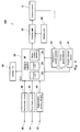
- the regenerative brake control system 100 includes the electric motor 5 as a driving power source, the battery unit 60 as an electric power supply unit for the electric motor 5, the inverter unit 20, a control unit 22 for controlling the electric motorcycle 1, operation members 30 to 35 placed in proper locations of the electric motorcycle 1, sensors 40 to 47 for detecting vehicle states, and a display unit 50 for displaying a speed, etc..
- the battery unit 60 as the electric power supply unit for the electric motor 5 is shown, and the control unit 22 and a low-voltage battery which is other electric component are not shown.
- the electric motor 5 is connected to the battery unit 60 via the inverter unit 20.
- the electric motor 5 performs power running as an electric motor during acceleration of the electric motorcycle 1 and performs regenerative running as an electric generator during deceleration of the electric motorcycle 1.
- the electric motor 5 operates with the AC power supplied from the inverter unit 20 to the electric motor 5 to generate the driving power for moving the vehicle body.
- the driving power generated in the electric motor 5 is transmitted to the rear wheel 3 via the driving power transmission mechanism 17.
- the electric motor 5 outputs driving torque as a driving force to the drive wheel through an output shaft thereof.
- the electric motor 5 generates the electric power with the rotational force transmitted from the rear wheel 3 to the electric motor 5.
- the electric power generated in the electric motor 5 is charged into the battery unit 60 via the inverter unit 20.
- the electric motor 5 generates regenerative torque as a braking force applied to the rear wheel 3 through the output shaft.
- the battery unit 60 is connected to the inverter unit 20 and configured to be charged and discharged via the inverter unit 20. During the power running of the electric motor 5, the battery unit 60 is discharged, while during the regenerative running of the electric motor 5, the battery unit 60 is charged.
- the control unit 22 includes a determiner section 23 configured to receive information input by the operation members 30 to 35 provided in the locations of the electric motorcycle 1, and other information indicating the vehicle states, from the sensors 40 to 47, and to determine whether or not a regeneration condition is satisfied based on the received information.
- the regeneration condition is defined as conditions relating to the vehicle states, which are used to determine whether or not to shift the electric motor 5 to the regenerative running.
- the determiner section 23 determines whether or not the electric motorcycle 1 is turning, when the regeneration condition is satisfied.
- the control unit 22 sets target torque based on the vehicle state, when the regeneration condition is satisfied based on the vehicle state, and suppresses a regenerative braking amount more when it is detected that the electric motorcycle 1 is turning than when it is detected that the electric motorcycle 1 is not turning.
- the specific configuration of the control unit 22 will be described.
- the control unit 22 includes a calculation section 24 configured to perform a target torque calculating process as will be described later, based on the information indicating the vehicle states which are detected by the sensors 40 to 47, according to a result of the determination performed by the determiner section 23.
- the target torque is defined as a target value of the output torque to be generated in the electric motor 5. In a case where the target torque is a positive value, this means that the control unit 22 provides a command to the inverter unit 20 and shifts the electric motor 5 to the power running to allow the electric motor 5 to generate driving torque which is equal to target driving torque.
- the control unit 22 provides a command to the inverter unit 20 and shifts the electric motor 5 to the regenerative running to allow the electric motor 5 to generate regenerative torque which is equal to target regenerative torque.
- the calculation section 24 decides the target torque based on the detected value of an accelerator operation amount and the detected value of a motor rotational speed. Then, the calculation section 24 provides the decided target torque to a motor control section 25. Furthermore, the calculation section 24 sets the value of the target torque such that a regenerative braking amount is suppressed more, when the electric motorcycle 1 is turning than when the electric motorcycle 1 is not turning.
- the control unit 22 includes the motor control section 25 configured to activate the electric motor 5 such that its speed is changeable, by using the inverter unit 20 as a power converter, and to control instantaneous torque of the electric motor 5 during the activation.
- the electric motor 5 is activated such that its speed is changeable by using the power converter in a well-known manner, which will not be described herein.
- the control unit 22 includes a storage section 26 configured to store data such as the reference torque, programs, information indicating the vehicle states detected by the sensors, etc..
- the storage section 26 may contain a torque map indicating the detected value of the accelerator operation amount and the value of the target torque defined by the detected value of the motor rotational speed.
- the control unit 22 is configured as a processor constituting a microcontroller or the like, and operation programs.
- the processor executes specified operation programs to perform the corresponding processing, thereby performing functions.
- the storage section 26 may be implemented by a memory of the microcontroller, or other external memory.
- the handle 8 as a steering device includes a pair of right and left grips 30, 36.
- the pair of right and left grips 30, 36 which are gripping members are provided at the right end portion and the left end portion of the handle 8, respectively.
- the right grip 30 is an accelerator grip for inputting an acceleration command (more specifically, torque command for the power running) for rotating the rear wheel 3 in an accelerative manner.
- the accelerator grip 30 is attached with an accelerator grip sensor 40.
- the accelerator grip sensor 40 provides to the control unit 22 an acceleration command corresponding to an angular displacement amount (hereinafter will be simply referred to as "accelerator operation amount") ⁇ from the reference position of the grip.
- the motor control section 25 of the control unit 22 adjusts the output torque of the electric motor 5 via the inverter unit 20, in response to this acceleration command.
- a brake lever 31 is placed in front of the accelerator grip 30.
- the brake lever 31 is an operation member which is operated to activate a front wheel brake mechanism (not shown) provided for the front wheel 2.
- a front wheel brake mechanism (not shown) provided for the front wheel 2.
- the front wheel brake mechanism is activated to apply a mechanical braking force to the front wheel 2.
- the brake lever 31 is attached with a brake sensor 41.
- the brake sensor 41 detects whether or not the brake lever 31 has been operated, and sends a detected signal to the control unit 22.
- a regeneration adjustment lever 32 is provided behind the left grip 36 of the handle 8.
- the regeneration adjustment lever 32 serves as a first operation member for adjusting the regenerative torque generated in the electric motor 5 during the regenerative running.
- the regeneration adjustment lever 32 can be gripped together with the left grip 36 with the rider's left thumb put on the regeneration adjustment lever 32.
- the regeneration adjustment lever 32 is pivotable to be away from a predetermined reference position.
- the regeneration adjustment lever 32 is applied with a biasing force for returning the regeneration adjustment lever 32 to the reference position.
- the regeneration adjustment lever 32 returns to the reference position.
- the regeneration adjustment lever 32 is attached with a regeneration amount sensor 42 for detecting the operation amount of the regeneration adjustment lever 32.
- the regeneration amount sensor 42 is a position sensor which outputs the adjustment command of the regenerative torque according to a position (i.e., operation amount) with respect to the predetermined reference position.
- the regeneration amount sensor 42 is connected to the control unit 22 and sends the adjustment command of the regenerative torque to the control unit 22.
- the control unit 22 adjusts the regenerative braking force of the electric motor 5 during the regenerative running, in response to the received adjustment command of the regenerative torque.
- the adjustment command of the regenerative torque is set so that the regenerative toque increases as the operation amount of the regeneration adjustment lever 32 increases. In this way, the regenerative toque can be adjusted to be increased easily.
- the electric motorcycle 1 includes a motor rotational speed sensor 43 and a vehicle speed sensor 44, as the sensors for detecting other vehicle states.
- the motor rotational speed sensor 43 and the vehicle speed sensor 44 are connected to the control unit 22, and send the detected signals to the control unit 22.
- the motor rotational speed sensor 43 detects the rotational speed of the electric motorcycle 5, while the vehicle speed sensor 44 detects the speed of the electric motorcycle 1.
- the electric motorcycle 1 includes an angular velocity sensor 45, as the sensor for detecting other vehicle state.
- the angular velocity sensor 45 is, for example, a gyro sensor, and detects an angular velocity ⁇ around a sensor center axis C4 set in a position which is angularly displaced with a predetermined inclination angle ⁇ with respect to a front-rear center axis C1, through a right-left center axis C2, in a plane including the front-rear center axis C1 and a vertical center axis C3.
- the angular velocity sensor 45 is connected to the control unit 22, and provides a detected signal to the control unit 22. When the electric motorcycle 1 is turning, the angular velocity sensor 45 detects a positive acceleration rate ⁇ .
- the electric motorcycle 1 includes the display unit 50 for displaying the speed, and others.
- the display unit 50 displays the vehicle states based on the information sent from the control unit 22 to the display unit 50.
- a display panel 51 of the display unit 50 is implemented by an instrument panel and placed in front of the handle bar 8 at the center in a vehicle width direction.
- the display panel 51 includes a speed display section 52 which displays the speed per hour in a digital format, a motor rotational speed display section 53 which displays the rotational speed of the electric motor 5, a regenerative torque display section 54 which displays the regenerative torque, an accelerative torque display section 55, a SOC (state of charge) display section 56 which displays the SOC of the battery, and a regeneration limit display section 57.
- a driving mode, a gear ratio, a driving distance, a time, etc.. may be displayed on the display panel 51.
- the regenerative torque display section 54 is configured to display the regenerative torque generated in the electric motor 5, in a bar representation.
- the regenerative torque display section 54 may be configured to display a numeric value in a digital format, for example, so long as the rider can check the amount of regenerative torque.
- the regeneration limit display section 57 displays that the output value of the regenerative torque has reached an allowable limit value, independently of the regenerative torque display section 54. In the present embodiment, the regeneration limit display section 57 displays that the output value of the regenerative torque has reached the allowable limit value, by turning ON a lamp. Since the regeneration limit display section 57 displays the limit value, the rider (user) can recognize that a present regenerative braking torque amount is the limit value, and can determine that further regenerative braking is inhibited. For example, the regeneration limit display section 57 may notify the rider that the output value of the regenerative torque has reached the allowable limit value, for example, by changing a color, or emitting a sound. In this way, the rider can know the regeneration amount and the limit value, which is helpful for the rider's operation.
- the handle 8 is attached with a main switch (not shown) which provides a command for starting to supply the electric power to the major electric components of the electric motorcycle 1 or ceasing to supply the electric power to the major electric components.
- the main switch is also configured to activate the regenerative brake control system 100.
- the main switch may be, for example, a push button switch, a rotatable switch which is inserted and rotated, such as a key cylinder, or a switch configured to provide a start command by holding, over the switch, an IC card or a portable terminal which enables wireless communication.
- the electric motorcycle 1 has started and is driving on a road in an accelerative manner or at a constant speed, in a state in which the electric motor 5 is in the power running state.
- the processing performed by the control unit 22 sequentially occurs in predetermined calculating process cycles.
- the determiner section 23 of the control unit 22 determines whether or not the vehicle state of the electric motorcycle 1 being driving on the road in an accelerative manner or at a constant speed satisfies the regeneration condition (step 1).
- the regeneration condition is defined as the condition relating to any of the vehicle states, which is used to determine whether or not to shift the electric motor 5 to the regenerative running.
- the regeneration condition is such that the accelerator operation amount is 0[%] and a driving speed is equal to or higher than 2[km/h].
- the determiner section 23 determines whether or not the regeneration condition is satisfied based on the detected value received from the accelerator grip sensor 40 and the detected value received from the vehicle speed sensor 44.
- the accelerator operation amount is 0[%]
- the accelerator grip 30 is returned from the reference position to an operation amount which is within a specified range (e.g., the angular displacement amount ⁇ of the grip is equal to or larger than 0 degree and equal to or smaller than 1 degree).
- the calculation section 24 of the control unit 22 sets reference regenerative torque T rr which is the reference value of the target torque according to the vehicle state to cause the electric motor 5 to generate the regenerative torque (step S2).
- the reference regenerative torque is set to a negative value, based on the detected value of the motor rotational speed and the detected value of the accelerator operation amount.
- the calculation section 24 sets the reference regenerative torque T rr as the reference value of the target torque, based on the detected value received from the accelerator grip sensor 40 and the detected value received from the motor rotational speed sensor 43.
- the determiner section 23 of the control unit 22 determines whether or not the electric motorcycle 1 is turning (step S3).
- the determiner section 23 determines whether or not the electric motorcycle 1 is turning, based on the detected value received from the angular velocity sensor 45.
- the acceleration rate ⁇ detected by the angular velocity sensor 45 is a positive value, the determiner section 23 determines that the electric motorcycle 1 is turning.
- the calculation section 24 calculates a lean angle ⁇ of the vehicle body (step S4).
- the lean angle ⁇ of the vehicle body is defined as an angle formed when the vehicle body of the electric motorcycle 1 being turning is banked from a vertical direction.
- the lean angle ⁇ of the vehicle body is 0 degree when the vehicle body is standing in an upright position, while the lean angle ⁇ of the vehicle body is 90 degrees when the vehicle body is placed horizontally.
- the calculation section 24 calculates the lean angle ⁇ of the vehicle body of the electric motorcycle 1, based on the angular velocity ⁇ detected by the angular velocity sensor 45, the inclination angle ⁇ of the sensor, and the speed V detected by the vehicle speed sensor 44.
- the angular velocity sensor 45 detects the angular velocity ⁇ around the sensor center axis C4 set in a position which is angularly displaced with a predetermined inclination angle ⁇ with respect to the front-rear center axis C1, through the right-left center axis C2, in the plane including the front-rear center axis C1 and the vertical center axis C3 of the vehicle body of the electric motorcycle 1 being driving straight ahead.
- the lean angle ⁇ may be calculated based on the lean angle ⁇ by a known method.
- the calculation section 24 of the control unit 22 sets the limit value L of the target torque based on the lean angle ⁇ calculated in step S4 (step S5).
- the limit value L of the target torque is set to a value that allows the regenerative braking amount to be less when the electric motorcycle 1 is turning than when the electric motorcycle 1 is not turning. Since the regenerative braking amount is suppressed more when the electric motorcycle 1 is turning than when the the electric motorcycle 1 is not turning, it becomes possible to prevent the regenerative braking amount from becoming excess, and avoid that driving feeling is negatively affected by the regenerative braking.
- the limit value L of the target torque is such that the degree to which the regenerative braking amount is suppressed, is changed based on the lean angle ⁇ .
- the control unit 22 compensates the reference regenerative torque T rr , in response to the input operation of the adjustment lever 32 (step 6). Specifically, the determiner section 23 determines whether or not the regeneration adjustment lever 32 has been operated to input a command, based on the detected value of the regeneration amount sensor 42.
- the calculation section 24 of the control unit 22 calculates the compensation amount of the reference regenerative torque T rr , based on the operation amount of the regeneration adjustment lever 32, i.e., the adjustment command of the regenerative torque which is detected by the regeneration amount sensor 42, and compensates the value of the reference regenerative torque T rr , based on the calculated compensation amount. Since the regeneration amount can be adjusted by using the regeneration adjustment lever 32, the regenerative braking amount can be increased according to the rider's intention.
- the calculation section 24 of the control unit 22 calculates target torque T rc (step S7).
- the calculation section 24 of the control unit 22 sets the reference regenerative torque T rr as the target torque T rc .
- the calculation section 24 of the control unit 22 sets the limit value L of the target torque as the target torque T rc .
- the calculation section 24 provides the calculated target torque T rc to the motor control section 25. This makes it possible to limit the regenerative braking amount more when the electric motorcycle 1 is turning than when the electric motorcycle 1 is not turning.
- step S3 the calculation section 24 sets the reference regenerative torque T rr as the target torque T rc . This is because the limit value L of the target torque for the state in which the electric motorcycle 1 is not turning is set to a value which is smaller than the value of the reference regenerative torque T rr . Then, the calculation section 24 provides the target torque T rc to the motor control section 25. Then, the motor control section 25 provides the control command corresponding to the target torque T rc to the electric motor 5.
- step 1 the power running of the electric motor 5 is continued.
- the calculation section 24 sets the reference driving torque T rd according to the vehicle state (step 8).
- the reference driving torque is set to a positive value based on the detected value of the motor rotational speed and the detected value of the accelerator operation amount.
- the calculation section 24 sets the reference driving torque which is the reference target torque based on the inputs which are the detected value received from the accelerator grip sensor 40 and the detected value received from the motor rotational speed sensor 43.
- the calculation section 24 provides to the motor control section 25 the target torque T rc which is equal to the reference driving torque T rd .
- the electric motorcycle 1 continues to drive in an accelerative manner or at a constant speed.
- Fig. 6 is a graph schematically showing the characteristic of the output torque generated in the electric motor 5 in the regenerative brake control system 100.
- a horizontal axis indicates the motor rotational speed, while a vertical axis indicates the motor output torque.
- Curves in the positive value range of the output torque indicate the characteristics of the output torque of the electric motor 5 during the power running, such that these curves correspond to the accelerator operation amounts, respectively. These curves indicate the torque characteristics corresponding to the accelerator operation amounts of 100%, 90%, 80%, 70% and 50%, respectively, from the upper. As can be seen from these graphs, the driving torque generated in the electric motor 5 during the power running increases, as the accelerator operation amount increases.
- a curve in the negative value range of the output torque indicates the characteristic of the output torque of the electric motor 5 during the regenerative running (accelerator operation amount is 0%).
- broken lines indicate the limit values L1 to L5 of the target torque, based on the lean angles ⁇ , respectively.
- L1 indicates a state in which the lean angle ⁇ is 0 degree, i.e., the limit value of the target torque for the state in which the electric motorcycle 1 is not turning.
- L2 to L5 indicates the limit values of the target torque, corresponding to cases where the lean angles ⁇ are 10 degrees, 20 degrees, 30 degrees, and 40 degrees, respectively.
- the limit value L of the target torque is set such that its absolute value decreases in proportion to the magnitude of the lean angle ⁇ .
- the regenerative braking amount is not limited to a high degree, when the lean angle of the vehicle body is small during the turn, which can prevent an unwanted limitation on regenerative braking.
- the regenerative braking amount is limited to a high degree when the lean angle of the vehicle body is large during the turn, which can prevent the regenerative braking force from becoming excess.
- the limit value of the regenerative braking is changed. Specifically, when the regenerative braking amount is set small, the regenerative braking amount can be set equal for the case where the electric motorcycle 1 is turning and for the case where the electric motorcycle 1 is not turning. Thus, the occasions in which the regenerative braking occurs during the turn are reduced, and as a result, the rider's discomfort can be reduced.
- Fig. 7 is a graph schematically showing the characteristic of output torque of the electric motor in a case where the regenerative torque is adjusted by using the regeneration adjustment lever 32 in the regenerative brake control system.
- a curve in a negative value range of the output torque indicates the output torque characteristic of the electric motor 5 in regenerative running (accelerator operation amount is 0%).
- the output torque characteristic of the electric motor 5 changes with a change in the operation amount of the regeneration adjustment lever 32, during the regenerative running.
- the adjustment command of the regenerative torque is set such that the regenerative torque increases as the displacement amount of the regeneration adjustment lever 32 increases.
- the regenerative torque characteristic increases with an increase in the operation amount of the regeneration adjustment lever 32.
- the regenerative torque exceeds the limit value L, the regenerative torque is limited such that the limit value L becomes the regenerative torque.
- the regeneration adjustment lever 32 Since the regenerative torque does not exceed the limit value even though the adjustment command for increasing the regenerative braking amount, is provided by the regeneration adjustment lever 32, it becomes possible to prevent a situation in which the target torque associated with the operation of the regeneration adjustment lever 32 exceeds the limit value, and it becomes possible to prevent the regenerative braking amount from becoming excess.
- the operation of the regeneration adjustment lever 32 may be handled with a priority, and the regenerative braking may be performed according to the rider's intention such that the target torque exceeds the limit value.
- the regenerative braking amount can be made close to that in the case where the electric motorcycle 1 is not turning, by the rider's operation of the regeneration adjustment lever 32. This can eliminate a need to set the limit value precisely. As a result, the limit value can be set easily.
- the limit value (regeneration suppression amount) may be set based on other vehicle states. For example, when it is determined that the electric motorcycle 1 is turning at a high speed, the regeneration braking amount may be decreased. It may be determined that the electric motorcycle 1 is turning at a high speed, based on one of the driving speed, the turn radius, and the lean angle. However, by using several of the driving speed, the turn radius, and the lean angle, determination accuracy can be made high.
- the limit value may be calculated based on a vehicle state amount, for example, by proportional calculation. This makes it possible to derive the regenerative braking amount in multiple stages, and to decide a proper braking amount.
- the limit value may be set based on a change in the lean angle which occurs with time, a change in a brake operation amount which occurs with time and is just before the turn is initiated, or a change in an accelerator operation amount which occurs with time and is just before the turn is initiated.
- the lean angle, the brake operation amount, or the accelerator operation amount significantly change with a passage of time, the driving state changes significantly, and therefore, the regenerative braking amount is preferably suppressed during the turn.
- the degree to which the regenerative braking amount is suppressed during the turn may be reduced.
- the regenerative braking amount is preferably suppressed during the turn.
- the limit value of the regenerative braking amount is made less when the electric motorcycle 1 is turning than when the electric motorcycle 1 is not turning
- other embodiment may be employed, so long as the regenerative braking amount can be suppressed when the electric motorcycle 1 is turning.
- the regenerative braking amount may be made less when the electric motorcycle 1 is turning than when the electric motorcycle 1 is not turning. More specifically, in step S2 of Fig. 5 , the regenerative braking torque may be made smaller when the electric motorcycle 1 is turning than when the electric motorcycle 1 is not turning.
- Fig. 8 is a graph showing the output torque characteristic of the electric motor, corresponding to the lean angle.
- Curves indicate the regenerative torque characteristics corresponding to the lean angle of 0 degree, the lean angle of 10 degrees, and the lean angle 40 degrees, respectively, from the lower.
- the reference regenerative torque is set smaller when the electric motorcycle 1 is turning (lean angle: 10 degrees, 40 degrees) than when the electric motorcycle 1 is not turning (lean angle: 0 degree), so that the characteristic of the regenerative torque generated in the electric motor changes.
- the regenerative braking amount may be changed during the turn, based on the lean angle. By reducing the regenerative braking amount when the lean angle is large, excess regenerative braking can be prevented during the turn. Also, as in the above described embodiment, the regenerative braking amount may be changed during the turn, based on the driving speed or the turn radius, instead of the lean angle. This makes it possible to obtain a proper regenerative braking amount corresponding to the driving state.
- the turn state is determined by using the angular velocity sensor
- the present invention is not limited to this, and the turn state may be determined by using a turn detecting means, which is other than the angular velocity sensor.
- a position sensor or direction sensor used in GPS may be used.
- the turn state may be detected by using a steering angle sensor for detecting the angular displacement amount of the handle. In this way, the turn state may be detected by using known sensors.
- the lean angle may be determined by using a detecting means which is other than the angular velocity sensor.
- a level sensor may be used.
- the lean angle may be calculated based on the turn angle and the driving speed.
- the regeneration adjustment lever is provided to adjust the target torque value by using the regeneration adjustment lever, the regeneration adjustment lever may be omitted.
- the regenerative brake control system may allow the rider to select whether or not to perform the control for suppressing the regenerative braking. Or, the the regenerative brake control system may allow the rider to select the level to which the regenerative braking is suppressed.
- the reference regenerative torque is set based on the detected value of the motor rotational speed and the detected value of the accelerator operation amount, the present invention is not limited to this.
- the reference regenerative torque may be set based on the vehicle state which is other than the state of the regeneration operation member, such as a change gear ratio, as well as the motor rotational speed and the accelerator operation amount.
- the regeneration condition is such that the accelerator operation amount is 0[%] and the driving speed is equal to or higher than 2[km/h], the present invention is not limited to this.
- the regeneration condition may be such that the accelerator operation amount is less than a predetermined value which is other than 0[%].
- the driving speed is not limited to the value which is equal to or higher than 2[km/h], and may be equal to or higher than a predetermined speed which is other than 2km/h.
- the electric motor 5 is not particularly limited so long as the instantaneous torque of the electric motor 5 can be controlled by using the power converter.
- the electric motor 5 may be a DC motor.
- the limit value of the target torque is set smaller in proportion to the magnitude of the lean angle during the turn of the vehicle
- the present invention is not limited to this.
- the limit value of the target torque may be decreased in proportion to the driving speed during the turn of the vehicle. In this case, when the driving speed of the vehicle is low during the turn, the regenerative braking amount is not suppressed to a high degree. This can prevent an undesired limitation on the regenerative braking.
- the limit value of the target torque may be decided based on both of the lean angle and the driving speed. In this case, since the limit value can be set based on the turn radius decided based on both of the vehicle speed and the lean angle, an undesired limitation on the regenerative braking can be suppressed.
- the present invention is applicable to an electric vehicle which is other than the two-wheeled vehicle.
- the present invention is applicable to a four-wheeled vehicle.
- the present invention is applicable to an ATV (all terrain vehicle), PWC (personal watercraft), or other hybrid vehicles.
- the present invention can effectively improve driving feeling during turn of an electric vehicle.
Landscapes
- Engineering & Computer Science (AREA)
- Mechanical Engineering (AREA)
- Transportation (AREA)
- Power Engineering (AREA)
- Life Sciences & Earth Sciences (AREA)
- Sustainable Development (AREA)
- Sustainable Energy (AREA)
- Physics & Mathematics (AREA)
- Electromagnetism (AREA)
- Electric Propulsion And Braking For Vehicles (AREA)
Applications Claiming Priority (1)
| Application Number | Priority Date | Filing Date | Title |
|---|---|---|---|
| PCT/JP2012/006749 WO2014064730A1 (fr) | 2012-10-22 | 2012-10-22 | Système de réglage de frein régénératif pour véhicule électrique |
Publications (3)
| Publication Number | Publication Date |
|---|---|
| EP2910400A1 true EP2910400A1 (fr) | 2015-08-26 |
| EP2910400A4 EP2910400A4 (fr) | 2016-07-27 |
| EP2910400B1 EP2910400B1 (fr) | 2020-03-25 |
Family
ID=50544136
Family Applications (1)
| Application Number | Title | Priority Date | Filing Date |
|---|---|---|---|
| EP12887222.3A Active EP2910400B1 (fr) | 2012-10-22 | 2012-10-22 | Système de réglage de frein régénératif d'un véhicule électrique |
Country Status (5)
| Country | Link |
|---|---|
| US (1) | US9457668B2 (fr) |
| EP (1) | EP2910400B1 (fr) |
| JP (1) | JP5865509B2 (fr) |
| CN (1) | CN104703837B (fr) |
| WO (1) | WO2014064730A1 (fr) |
Cited By (1)
| Publication number | Priority date | Publication date | Assignee | Title |
|---|---|---|---|---|
| EP3147192A3 (fr) * | 2015-09-28 | 2017-06-21 | Yamaha Hatsudoki Kabushiki Kaisha | Vehicule electrique a enfourcher |
Families Citing this family (34)
| Publication number | Priority date | Publication date | Assignee | Title |
|---|---|---|---|---|
| US9387764B2 (en) * | 2012-10-22 | 2016-07-12 | Kawasaki Jukogyo Kabushiki Kaisha | Regenerative brake control system of electric vehicle |
| US10011323B2 (en) * | 2012-12-25 | 2018-07-03 | Kawasaki Jukogyo Kabushiki Kaisha | Electric vehicle |
| WO2014102851A1 (fr) * | 2012-12-25 | 2014-07-03 | 川崎重工業株式会社 | Véhicule électrique |
| DE102013220426B3 (de) * | 2013-10-10 | 2015-03-19 | Continental Automotive Gmbh | Verfahren zum Betreiben eines Fahrzeugs und Fahrerassistenzsystem für ein Fahrzeug |
| JP6299476B2 (ja) * | 2014-06-23 | 2018-03-28 | 三菱自動車工業株式会社 | 運転支援装置 |
| WO2016017297A1 (fr) * | 2014-07-28 | 2016-02-04 | ボッシュ株式会社 | Dispositif et programme de fourniture d'informations pour motocyclette |
| JP5945572B2 (ja) * | 2014-09-03 | 2016-07-05 | ヤマハ発動機株式会社 | 駆動力制御システムおよび鞍乗り型車両 |
| JP6241616B2 (ja) * | 2014-12-04 | 2017-12-06 | トヨタ自動車株式会社 | 車両用制動力制御装置 |
| ES2926998T3 (es) * | 2015-03-05 | 2022-10-31 | Energica Motor Company S P A | Motocicleta eléctrica con sistema antibloqueo de ruedas |
| JP6475047B2 (ja) * | 2015-03-18 | 2019-02-27 | ブリヂストンサイクル株式会社 | 電動機付自転車 |
| WO2016203452A1 (fr) * | 2015-06-17 | 2016-12-22 | Consortium De Recherche Brp – Universite De Sherbrooke S.E.N.C. | Système et procédé de freinage à récupération |
| US9966785B2 (en) * | 2015-07-10 | 2018-05-08 | Shimano Inc. | Bicycle control system |
| CN104986055A (zh) * | 2015-07-11 | 2015-10-21 | 河南机电高等专科学校 | 一种电动自行车加速度控制器 |
| JP6701662B2 (ja) * | 2015-10-07 | 2020-05-27 | 三菱自動車工業株式会社 | 電動車の回生制動制御装置 |
| EP3437945B1 (fr) * | 2016-03-31 | 2021-05-12 | Honda Motor Co., Ltd. | Dispositif de commande de frein pour motocyclette |
| CN106005127A (zh) * | 2016-07-13 | 2016-10-12 | 天津聚盛龙庄源科技有限公司 | 一种轻便环保智能代步车 |
| DE102016213265A1 (de) * | 2016-07-20 | 2018-01-25 | Continental Automotive Gmbh | Regelungsverfahren für einen elektrischen Antrieb eines Zweirads |
| JP6639362B2 (ja) * | 2016-09-08 | 2020-02-05 | ブリヂストンサイクル株式会社 | 電動機付自転車 |
| JP2018154272A (ja) * | 2017-03-21 | 2018-10-04 | ローベルト ボッシュ ゲゼルシャフト ミット ベシュレンクテル ハフツング | 制御装置及び制御方法 |
| JP6830882B2 (ja) * | 2017-10-20 | 2021-02-17 | 株式会社シマノ | ブレーキ制御装置およびブレーキシステム |
| GB2568503B (en) * | 2017-11-17 | 2021-08-04 | Jaguar Land Rover Ltd | A motorcycle |
| GB2568505B (en) * | 2017-11-17 | 2020-05-27 | Jaguar Land Rover Ltd | A motorcycle |
| JP7155517B2 (ja) * | 2017-12-21 | 2022-10-19 | 三菱自動車工業株式会社 | 走行制御装置 |
| JP2019131133A (ja) * | 2018-02-02 | 2019-08-08 | マツダ株式会社 | 車両の制御方法、車両システム及び車両の制御装置 |
| JP2020050220A (ja) * | 2018-09-28 | 2020-04-02 | ロベルト・ボッシュ・ゲゼルシャフト・ミト・ベシュレンクテル・ハフツングRobert Bosch Gmbh | 制御装置及び制御方法 |
| JP7205989B2 (ja) * | 2018-12-26 | 2023-01-17 | カワサキモータース株式会社 | バッテリパックおよびそれを備える移動体 |
| US11866117B2 (en) | 2019-01-16 | 2024-01-09 | Livewire Ev, Llc | Motorcycle with virtual braking and virtual clutch |
| JP2020175830A (ja) * | 2019-04-22 | 2020-10-29 | ロベルト・ボッシュ・ゲゼルシャフト・ミト・ベシュレンクテル・ハフツングRobert Bosch Gmbh | 制御装置及び制御方法 |
| EP3730391A1 (fr) * | 2019-04-25 | 2020-10-28 | Robert Bosch GmbH | Procédé pour avertir le conducteur d'une motocyclette ainsi qu'un organe de commande d'assistant à la conduite et motocyclette mettant en uvre un tel procédé |
| DE112020003109T5 (de) * | 2019-06-27 | 2022-05-05 | Alps Alpine Co., Ltd. | Betätigungsvorrichtung |
| CN112677945A (zh) * | 2020-12-31 | 2021-04-20 | 拿森汽车科技(杭州)有限公司 | 制动能量回收控制方法及系统 |
| US11958383B2 (en) | 2021-03-14 | 2024-04-16 | Toyota Motor Engineering & Manufacturing North America, Inc. | Regenerative braking control system |
| US20220289036A1 (en) * | 2021-03-14 | 2022-09-15 | Toyota Motor Engineering & Manufacturing North America, Inc. | Regenerative braking control system |
| CN116135578B (zh) * | 2023-04-17 | 2023-07-07 | 富士达电动车(江苏)有限公司 | 一种电动车的节能续航控制机构 |
Family Cites Families (20)
| Publication number | Priority date | Publication date | Assignee | Title |
|---|---|---|---|---|
| US4989922A (en) | 1988-11-23 | 1991-02-05 | Lucas Industries Public Limited Company | Method of anti-lock brake control for motorcycle vehicle |
| JPH0638305A (ja) * | 1992-07-17 | 1994-02-10 | Aqueous Res:Kk | ハイブリッド型車両 |
| JPH0879907A (ja) * | 1994-09-01 | 1996-03-22 | Mitsubishi Motors Corp | 電気自動車用回生ブレーキ制御装置 |
| JP3622395B2 (ja) * | 1997-01-17 | 2005-02-23 | トヨタ自動車株式会社 | 制動装置 |
| JP2001039281A (ja) * | 1999-07-30 | 2001-02-13 | Mazda Motor Corp | 車両の制動装置 |
| JP3882993B2 (ja) * | 2001-11-02 | 2007-02-21 | 本田技研工業株式会社 | 電動車両の回生制御装置 |
| JP2005143274A (ja) | 2003-11-10 | 2005-06-02 | Nissan Motor Co Ltd | 電動車両の駆動制御装置及び駆動制御方法 |
| JP2005153842A (ja) * | 2003-11-20 | 2005-06-16 | Sofutoronikusu Kk | 電動モータ付き自転車のブレーキ制御装置 |
| US7409280B2 (en) * | 2004-01-15 | 2008-08-05 | Nissan Motor Co., Ltd. | Vehicle braking control apparatus |
| JP4631477B2 (ja) | 2005-03-04 | 2011-02-16 | 日産自動車株式会社 | 車両の回生制動制御装置 |
| JP4230483B2 (ja) | 2005-11-14 | 2009-02-25 | マイコム株式会社 | 自動二輪車 |
| JP2008301590A (ja) * | 2007-05-30 | 2008-12-11 | Honda Motor Co Ltd | 電動車両 |
| JP4458300B2 (ja) * | 2007-10-25 | 2010-04-28 | 本田技研工業株式会社 | 電動車両、および電動車両の回生制御方法 |
| US8640809B2 (en) * | 2010-01-05 | 2014-02-04 | Honda Motor Company, Ltd. | Flywheel assemblies and vehicles including same |
| US8706390B2 (en) * | 2010-03-16 | 2014-04-22 | Lit Motors Corporation | Gyroscopic stabilized vehicle |
| US8973690B2 (en) * | 2010-10-04 | 2015-03-10 | W. Morrision Consulting Group, Inc. | Front wheel energy recovery system |
| EP2453203A1 (fr) | 2010-11-10 | 2012-05-16 | Pilot Ltd | Capteur d'orientation |
| US9096132B2 (en) * | 2010-12-28 | 2015-08-04 | Kawasaki Jukogyo Kabushiki Kaisha | Regeneration control system in electric vehicle |
| CN103153723B (zh) * | 2011-06-27 | 2015-06-10 | 日产自动车株式会社 | 车辆制动控制装置 |
| US9718359B2 (en) * | 2011-08-30 | 2017-08-01 | Ford Global Technologies, Llc | Braking display system and method |
-
2012
- 2012-10-22 CN CN201280076472.4A patent/CN104703837B/zh active Active
- 2012-10-22 JP JP2014543005A patent/JP5865509B2/ja active Active
- 2012-10-22 WO PCT/JP2012/006749 patent/WO2014064730A1/fr active Application Filing
- 2012-10-22 US US14/437,188 patent/US9457668B2/en active Active
- 2012-10-22 EP EP12887222.3A patent/EP2910400B1/fr active Active
Cited By (2)
| Publication number | Priority date | Publication date | Assignee | Title |
|---|---|---|---|---|
| EP3147192A3 (fr) * | 2015-09-28 | 2017-06-21 | Yamaha Hatsudoki Kabushiki Kaisha | Vehicule electrique a enfourcher |
| US9950641B2 (en) | 2015-09-28 | 2018-04-24 | Yamaha Hatsudoki Kabushiki Kaisha | Straddle-type electric vehicle |
Also Published As
| Publication number | Publication date |
|---|---|
| CN104703837B (zh) | 2017-03-08 |
| JPWO2014064730A1 (ja) | 2016-09-05 |
| US9457668B2 (en) | 2016-10-04 |
| EP2910400B1 (fr) | 2020-03-25 |
| EP2910400A4 (fr) | 2016-07-27 |
| CN104703837A (zh) | 2015-06-10 |
| US20150274019A1 (en) | 2015-10-01 |
| JP5865509B2 (ja) | 2016-02-17 |
| WO2014064730A1 (fr) | 2014-05-01 |
Similar Documents
| Publication | Publication Date | Title |
|---|---|---|
| US9457668B2 (en) | Regenerative brake control system of electric vehicle | |
| EP2910402B1 (fr) | Système de réglage de frein régénératif de véhicule électrique | |
| EP2910401B1 (fr) | Systeme de commande de frein regeneratif de vehicule electrique | |
| US9889845B2 (en) | Straddled vehicle | |
| EP2711285B1 (fr) | Bicyclette électrique et son procédé de contrôle | |
| EP2476605B1 (fr) | Véhicule à deux roues, appareil de stabilisation d'attitude et procédé de stabilisation d'attitude | |
| US11124268B2 (en) | Human-powered vehicle control device | |
| WO2012090253A1 (fr) | Système de commande de régénération pour véhicule électrique | |
| JP7379324B2 (ja) | モータ制御装置及び電動アシスト車 | |
| TW201924965A (zh) | 車輛 | |
| JP2016107738A (ja) | 電動補助自転車 | |
| US20220203979A1 (en) | Controller and control method | |
| JP2005255074A (ja) | スケータ型車両 | |
| JP2005349887A (ja) | 車両運動制御装置 | |
| US20130274983A1 (en) | Acceleration Control System in Electric Vehicle | |
| JP2006298094A (ja) | 車両停止保持装置 | |
| WO2018030407A1 (fr) | Véhicule | |
| US20230007882A1 (en) | Tetherless shutoff systems and methods for powersport vehicles | |
| JP2012030642A (ja) | 操舵力制御装置 | |
| JP2024051219A (ja) | 人力駆動車用の制御装置 | |
| JP2021049848A (ja) | 制御装置 |
Legal Events
| Date | Code | Title | Description |
|---|---|---|---|
| PUAI | Public reference made under article 153(3) epc to a published international application that has entered the european phase |
Free format text: ORIGINAL CODE: 0009012 |
|
| 17P | Request for examination filed |
Effective date: 20150522 |
|
| AK | Designated contracting states |
Kind code of ref document: A1 Designated state(s): AL AT BE BG CH CY CZ DE DK EE ES FI FR GB GR HR HU IE IS IT LI LT LU LV MC MK MT NL NO PL PT RO RS SE SI SK SM TR |
|
| AX | Request for extension of the european patent |
Extension state: BA ME |
|
| DAX | Request for extension of the european patent (deleted) | ||
| RA4 | Supplementary search report drawn up and despatched (corrected) |
Effective date: 20160623 |
|
| RIC1 | Information provided on ipc code assigned before grant |
Ipc: B60L 7/10 20060101AFI20160617BHEP Ipc: B62J 99/00 20090101ALI20160617BHEP |
|
| STAA | Information on the status of an ep patent application or granted ep patent |
Free format text: STATUS: EXAMINATION IS IN PROGRESS |
|
| 17Q | First examination report despatched |
Effective date: 20181207 |
|
| GRAP | Despatch of communication of intention to grant a patent |
Free format text: ORIGINAL CODE: EPIDOSNIGR1 |
|
| STAA | Information on the status of an ep patent application or granted ep patent |
Free format text: STATUS: GRANT OF PATENT IS INTENDED |
|
| INTG | Intention to grant announced |
Effective date: 20191001 |
|
| GRAS | Grant fee paid |
Free format text: ORIGINAL CODE: EPIDOSNIGR3 |
|
| GRAA | (expected) grant |
Free format text: ORIGINAL CODE: 0009210 |
|
| STAA | Information on the status of an ep patent application or granted ep patent |
Free format text: STATUS: THE PATENT HAS BEEN GRANTED |
|
| RIN1 | Information on inventor provided before grant (corrected) |
Inventor name: MATSUDA, YOSHIMOTO |
|
| AK | Designated contracting states |
Kind code of ref document: B1 Designated state(s): AL AT BE BG CH CY CZ DE DK EE ES FI FR GB GR HR HU IE IS IT LI LT LU LV MC MK MT NL NO PL PT RO RS SE SI SK SM TR |
|
| REG | Reference to a national code |
Ref country code: GB Ref legal event code: FG4D |
|
| REG | Reference to a national code |
Ref country code: AT Ref legal event code: REF Ref document number: 1248187 Country of ref document: AT Kind code of ref document: T Effective date: 20200415 Ref country code: IE Ref legal event code: FG4D |
|
| REG | Reference to a national code |
Ref country code: DE Ref legal event code: R096 Ref document number: 602012068820 Country of ref document: DE |
|
| PG25 | Lapsed in a contracting state [announced via postgrant information from national office to epo] |
Ref country code: FI Free format text: LAPSE BECAUSE OF FAILURE TO SUBMIT A TRANSLATION OF THE DESCRIPTION OR TO PAY THE FEE WITHIN THE PRESCRIBED TIME-LIMIT Effective date: 20200325 Ref country code: NO Free format text: LAPSE BECAUSE OF FAILURE TO SUBMIT A TRANSLATION OF THE DESCRIPTION OR TO PAY THE FEE WITHIN THE PRESCRIBED TIME-LIMIT Effective date: 20200625 Ref country code: RS Free format text: LAPSE BECAUSE OF FAILURE TO SUBMIT A TRANSLATION OF THE DESCRIPTION OR TO PAY THE FEE WITHIN THE PRESCRIBED TIME-LIMIT Effective date: 20200325 |
|
| PG25 | Lapsed in a contracting state [announced via postgrant information from national office to epo] |
Ref country code: BG Free format text: LAPSE BECAUSE OF FAILURE TO SUBMIT A TRANSLATION OF THE DESCRIPTION OR TO PAY THE FEE WITHIN THE PRESCRIBED TIME-LIMIT Effective date: 20200625 Ref country code: GR Free format text: LAPSE BECAUSE OF FAILURE TO SUBMIT A TRANSLATION OF THE DESCRIPTION OR TO PAY THE FEE WITHIN THE PRESCRIBED TIME-LIMIT Effective date: 20200626 Ref country code: SE Free format text: LAPSE BECAUSE OF FAILURE TO SUBMIT A TRANSLATION OF THE DESCRIPTION OR TO PAY THE FEE WITHIN THE PRESCRIBED TIME-LIMIT Effective date: 20200325 Ref country code: LV Free format text: LAPSE BECAUSE OF FAILURE TO SUBMIT A TRANSLATION OF THE DESCRIPTION OR TO PAY THE FEE WITHIN THE PRESCRIBED TIME-LIMIT Effective date: 20200325 Ref country code: HR Free format text: LAPSE BECAUSE OF FAILURE TO SUBMIT A TRANSLATION OF THE DESCRIPTION OR TO PAY THE FEE WITHIN THE PRESCRIBED TIME-LIMIT Effective date: 20200325 |
|
| REG | Reference to a national code |
Ref country code: NL Ref legal event code: MP Effective date: 20200325 |
|
| REG | Reference to a national code |
Ref country code: LT Ref legal event code: MG4D |
|
| PG25 | Lapsed in a contracting state [announced via postgrant information from national office to epo] |
Ref country code: NL Free format text: LAPSE BECAUSE OF FAILURE TO SUBMIT A TRANSLATION OF THE DESCRIPTION OR TO PAY THE FEE WITHIN THE PRESCRIBED TIME-LIMIT Effective date: 20200325 |
|
| PG25 | Lapsed in a contracting state [announced via postgrant information from national office to epo] |
Ref country code: PT Free format text: LAPSE BECAUSE OF FAILURE TO SUBMIT A TRANSLATION OF THE DESCRIPTION OR TO PAY THE FEE WITHIN THE PRESCRIBED TIME-LIMIT Effective date: 20200818 Ref country code: LT Free format text: LAPSE BECAUSE OF FAILURE TO SUBMIT A TRANSLATION OF THE DESCRIPTION OR TO PAY THE FEE WITHIN THE PRESCRIBED TIME-LIMIT Effective date: 20200325 Ref country code: RO Free format text: LAPSE BECAUSE OF FAILURE TO SUBMIT A TRANSLATION OF THE DESCRIPTION OR TO PAY THE FEE WITHIN THE PRESCRIBED TIME-LIMIT Effective date: 20200325 Ref country code: SK Free format text: LAPSE BECAUSE OF FAILURE TO SUBMIT A TRANSLATION OF THE DESCRIPTION OR TO PAY THE FEE WITHIN THE PRESCRIBED TIME-LIMIT Effective date: 20200325 Ref country code: IS Free format text: LAPSE BECAUSE OF FAILURE TO SUBMIT A TRANSLATION OF THE DESCRIPTION OR TO PAY THE FEE WITHIN THE PRESCRIBED TIME-LIMIT Effective date: 20200725 Ref country code: CZ Free format text: LAPSE BECAUSE OF FAILURE TO SUBMIT A TRANSLATION OF THE DESCRIPTION OR TO PAY THE FEE WITHIN THE PRESCRIBED TIME-LIMIT Effective date: 20200325 Ref country code: SM Free format text: LAPSE BECAUSE OF FAILURE TO SUBMIT A TRANSLATION OF THE DESCRIPTION OR TO PAY THE FEE WITHIN THE PRESCRIBED TIME-LIMIT Effective date: 20200325 Ref country code: EE Free format text: LAPSE BECAUSE OF FAILURE TO SUBMIT A TRANSLATION OF THE DESCRIPTION OR TO PAY THE FEE WITHIN THE PRESCRIBED TIME-LIMIT Effective date: 20200325 |
|
| REG | Reference to a national code |
Ref country code: AT Ref legal event code: MK05 Ref document number: 1248187 Country of ref document: AT Kind code of ref document: T Effective date: 20200325 |
|
| REG | Reference to a national code |
Ref country code: DE Ref legal event code: R097 Ref document number: 602012068820 Country of ref document: DE |
|
| PG25 | Lapsed in a contracting state [announced via postgrant information from national office to epo] |
Ref country code: IT Free format text: LAPSE BECAUSE OF FAILURE TO SUBMIT A TRANSLATION OF THE DESCRIPTION OR TO PAY THE FEE WITHIN THE PRESCRIBED TIME-LIMIT Effective date: 20200325 Ref country code: AT Free format text: LAPSE BECAUSE OF FAILURE TO SUBMIT A TRANSLATION OF THE DESCRIPTION OR TO PAY THE FEE WITHIN THE PRESCRIBED TIME-LIMIT Effective date: 20200325 Ref country code: ES Free format text: LAPSE BECAUSE OF FAILURE TO SUBMIT A TRANSLATION OF THE DESCRIPTION OR TO PAY THE FEE WITHIN THE PRESCRIBED TIME-LIMIT Effective date: 20200325 Ref country code: DK Free format text: LAPSE BECAUSE OF FAILURE TO SUBMIT A TRANSLATION OF THE DESCRIPTION OR TO PAY THE FEE WITHIN THE PRESCRIBED TIME-LIMIT Effective date: 20200325 |
|
| PLBE | No opposition filed within time limit |
Free format text: ORIGINAL CODE: 0009261 |
|
| STAA | Information on the status of an ep patent application or granted ep patent |
Free format text: STATUS: NO OPPOSITION FILED WITHIN TIME LIMIT |
|
| PG25 | Lapsed in a contracting state [announced via postgrant information from national office to epo] |
Ref country code: PL Free format text: LAPSE BECAUSE OF FAILURE TO SUBMIT A TRANSLATION OF THE DESCRIPTION OR TO PAY THE FEE WITHIN THE PRESCRIBED TIME-LIMIT Effective date: 20200325 |
|
| 26N | No opposition filed |
Effective date: 20210112 |
|
| PG25 | Lapsed in a contracting state [announced via postgrant information from national office to epo] |
Ref country code: SI Free format text: LAPSE BECAUSE OF FAILURE TO SUBMIT A TRANSLATION OF THE DESCRIPTION OR TO PAY THE FEE WITHIN THE PRESCRIBED TIME-LIMIT Effective date: 20200325 |
|
| REG | Reference to a national code |
Ref country code: CH Ref legal event code: PL |
|
| GBPC | Gb: european patent ceased through non-payment of renewal fee |
Effective date: 20201022 |
|
| PG25 | Lapsed in a contracting state [announced via postgrant information from national office to epo] |
Ref country code: LU Free format text: LAPSE BECAUSE OF NON-PAYMENT OF DUE FEES Effective date: 20201022 Ref country code: MC Free format text: LAPSE BECAUSE OF FAILURE TO SUBMIT A TRANSLATION OF THE DESCRIPTION OR TO PAY THE FEE WITHIN THE PRESCRIBED TIME-LIMIT Effective date: 20200325 |
|
| REG | Reference to a national code |
Ref country code: BE Ref legal event code: MM Effective date: 20201031 |
|
| PG25 | Lapsed in a contracting state [announced via postgrant information from national office to epo] |
Ref country code: GB Free format text: LAPSE BECAUSE OF NON-PAYMENT OF DUE FEES Effective date: 20201022 Ref country code: LI Free format text: LAPSE BECAUSE OF NON-PAYMENT OF DUE FEES Effective date: 20201031 Ref country code: CH Free format text: LAPSE BECAUSE OF NON-PAYMENT OF DUE FEES Effective date: 20201031 Ref country code: BE Free format text: LAPSE BECAUSE OF NON-PAYMENT OF DUE FEES Effective date: 20201031 |
|
| PG25 | Lapsed in a contracting state [announced via postgrant information from national office to epo] |
Ref country code: IE Free format text: LAPSE BECAUSE OF NON-PAYMENT OF DUE FEES Effective date: 20201022 |
|
| PG25 | Lapsed in a contracting state [announced via postgrant information from national office to epo] |
Ref country code: TR Free format text: LAPSE BECAUSE OF FAILURE TO SUBMIT A TRANSLATION OF THE DESCRIPTION OR TO PAY THE FEE WITHIN THE PRESCRIBED TIME-LIMIT Effective date: 20200325 Ref country code: MT Free format text: LAPSE BECAUSE OF FAILURE TO SUBMIT A TRANSLATION OF THE DESCRIPTION OR TO PAY THE FEE WITHIN THE PRESCRIBED TIME-LIMIT Effective date: 20200325 Ref country code: CY Free format text: LAPSE BECAUSE OF FAILURE TO SUBMIT A TRANSLATION OF THE DESCRIPTION OR TO PAY THE FEE WITHIN THE PRESCRIBED TIME-LIMIT Effective date: 20200325 |
|
| REG | Reference to a national code |
Ref country code: DE Ref legal event code: R081 Ref document number: 602012068820 Country of ref document: DE Owner name: KAWASAKI MOTORS, LTD., AKASHI-SHI, JP Free format text: FORMER OWNER: KAWASAKI JUKOGYO KABUSHIKI KAISHA, KOBE-SHI, HYOGO, JP |
|
| PG25 | Lapsed in a contracting state [announced via postgrant information from national office to epo] |
Ref country code: MK Free format text: LAPSE BECAUSE OF FAILURE TO SUBMIT A TRANSLATION OF THE DESCRIPTION OR TO PAY THE FEE WITHIN THE PRESCRIBED TIME-LIMIT Effective date: 20200325 Ref country code: AL Free format text: LAPSE BECAUSE OF FAILURE TO SUBMIT A TRANSLATION OF THE DESCRIPTION OR TO PAY THE FEE WITHIN THE PRESCRIBED TIME-LIMIT Effective date: 20200325 |
|
| PGFP | Annual fee paid to national office [announced via postgrant information from national office to epo] |
Ref country code: FR Payment date: 20230911 Year of fee payment: 12 |
|
| PGFP | Annual fee paid to national office [announced via postgrant information from national office to epo] |
Ref country code: DE Payment date: 20230830 Year of fee payment: 12 |