EP2908425B1 - Apparatus for driving a plurality of permanent magnet synchronous motors using single inverter - Google Patents
Apparatus for driving a plurality of permanent magnet synchronous motors using single inverter Download PDFInfo
- Publication number
- EP2908425B1 EP2908425B1 EP15155482.1A EP15155482A EP2908425B1 EP 2908425 B1 EP2908425 B1 EP 2908425B1 EP 15155482 A EP15155482 A EP 15155482A EP 2908425 B1 EP2908425 B1 EP 2908425B1
- Authority
- EP
- European Patent Office
- Prior art keywords
- current
- motors
- motor
- leg
- pmsm
- Prior art date
- Legal status (The legal status is an assumption and is not a legal conclusion. Google has not performed a legal analysis and makes no representation as to the accuracy of the status listed.)
- Active
Links
- 230000001360 synchronised effect Effects 0.000 title description 7
- 238000006243 chemical reaction Methods 0.000 claims description 42
- 230000007935 neutral effect Effects 0.000 claims description 11
- 230000009466 transformation Effects 0.000 claims description 3
- 238000000034 method Methods 0.000 description 17
- 239000003990 capacitor Substances 0.000 description 8
- 230000004907 flux Effects 0.000 description 7
- 230000009977 dual effect Effects 0.000 description 5
- 230000006870 function Effects 0.000 description 3
- 230000006698 induction Effects 0.000 description 3
- 238000004088 simulation Methods 0.000 description 3
- 230000000116 mitigating effect Effects 0.000 description 2
- 230000003287 optical effect Effects 0.000 description 2
- 238000004364 calculation method Methods 0.000 description 1
- 230000005284 excitation Effects 0.000 description 1
- 238000004519 manufacturing process Methods 0.000 description 1
- 230000004048 modification Effects 0.000 description 1
- 238000012986 modification Methods 0.000 description 1
- 230000001105 regulatory effect Effects 0.000 description 1
Images


Classifications
-
- H—ELECTRICITY
- H02—GENERATION; CONVERSION OR DISTRIBUTION OF ELECTRIC POWER
- H02K—DYNAMO-ELECTRIC MACHINES
- H02K15/00—Methods or apparatus specially adapted for manufacturing, assembling, maintaining or repairing of dynamo-electric machines
-
- H—ELECTRICITY
- H02—GENERATION; CONVERSION OR DISTRIBUTION OF ELECTRIC POWER
- H02P—CONTROL OR REGULATION OF ELECTRIC MOTORS, ELECTRIC GENERATORS OR DYNAMO-ELECTRIC CONVERTERS; CONTROLLING TRANSFORMERS, REACTORS OR CHOKE COILS
- H02P5/00—Arrangements specially adapted for regulating or controlling the speed or torque of two or more electric motors
- H02P5/74—Arrangements specially adapted for regulating or controlling the speed or torque of two or more electric motors controlling two or more ac dynamo-electric motors
-
- H—ELECTRICITY
- H02—GENERATION; CONVERSION OR DISTRIBUTION OF ELECTRIC POWER
- H02K—DYNAMO-ELECTRIC MACHINES
- H02K11/00—Structural association of dynamo-electric machines with electric components or with devices for shielding, monitoring or protection
- H02K11/30—Structural association with control circuits or drive circuits
- H02K11/33—Drive circuits, e.g. power electronics
-
- H—ELECTRICITY
- H02—GENERATION; CONVERSION OR DISTRIBUTION OF ELECTRIC POWER
- H02P—CONTROL OR REGULATION OF ELECTRIC MOTORS, ELECTRIC GENERATORS OR DYNAMO-ELECTRIC CONVERTERS; CONTROLLING TRANSFORMERS, REACTORS OR CHOKE COILS
- H02P21/00—Arrangements or methods for the control of electric machines by vector control, e.g. by control of field orientation
- H02P21/22—Current control, e.g. using a current control loop
-
- H—ELECTRICITY
- H02—GENERATION; CONVERSION OR DISTRIBUTION OF ELECTRIC POWER
- H02P—CONTROL OR REGULATION OF ELECTRIC MOTORS, ELECTRIC GENERATORS OR DYNAMO-ELECTRIC CONVERTERS; CONTROLLING TRANSFORMERS, REACTORS OR CHOKE COILS
- H02P6/00—Arrangements for controlling synchronous motors or other dynamo-electric motors using electronic commutation dependent on the rotor position; Electronic commutators therefor
- H02P6/04—Arrangements for controlling or regulating the speed or torque of more than one motor
- H02P2006/045—Control of current
-
- Y—GENERAL TAGGING OF NEW TECHNOLOGICAL DEVELOPMENTS; GENERAL TAGGING OF CROSS-SECTIONAL TECHNOLOGIES SPANNING OVER SEVERAL SECTIONS OF THE IPC; TECHNICAL SUBJECTS COVERED BY FORMER USPC CROSS-REFERENCE ART COLLECTIONS [XRACs] AND DIGESTS
- Y10—TECHNICAL SUBJECTS COVERED BY FORMER USPC
- Y10T—TECHNICAL SUBJECTS COVERED BY FORMER US CLASSIFICATION
- Y10T29/00—Metal working
- Y10T29/49—Method of mechanical manufacture
- Y10T29/49002—Electrical device making
- Y10T29/49009—Dynamoelectric machine
Definitions
- One or more embodiments of the present disclosure relate to a motor driving apparatus using an inverter, and more particularly to driving a plurality of permanent magnet synchronous motors (PMSM) using a single inverter.
- PMSM permanent magnet synchronous motors
- an inverter is needed to apply a voltage level required to drive the PMSM.
- the voltage level of the PMSM may be variable depending on the speed and torque of the PMSM and a rotator flux position.
- a voltage phase may be variable according to a rotator flux position.
- a vector control method is mainly used for driving the PMSM.
- voltage is applied to place vector current at a position that is electrically forward from a rotator magnetic flux position by 90 degree. Therefore, when a plurality of PMSMs are driven, the same number of inverters is needed.
- the plurality of the PMSMs may be connected to the inverter in parallel.
- Stator coils on each phase of the plurality of PMSMs may be connected to a leg of the inverter corresponding to each phase so that the same voltage is applied to each PMSM of the plurality of PMSMs.
- the applied voltage level may be determined according to the voltage required by the PMSM having the largest load among the plurality of PMSMs.
- the same voltage level is applied to the plurality of PMSMs. If the plurality of PMSMs have the same parameter and load, the plurality of PMSMs may have the same performance. However, in practice, the plurality of PMSMs may have different parameters and loads due to manufacturing differences, so rotator positions may be variable in the plurality of the PMSMs. Therefore, the plurality of PMSMs each require different voltage levels. Various voltage levels, however, cannot be generated by a single inverter.
- a plurality of PMSMs may be driven at the same speed, and one or more of the plurality of PMSMs may be stepped out when the difference between the rotor positions is increased due to the difference in speed of the PMSMs from each other.
- at least two current sensors may be needed for each PMSM. For example, when N PMSMs may be driven by a single inverter, 2N current sensors may be needed in total.
- Dual AC-Drive System With a Reduced Switch Count discloses a dual current-regulated pulsewidth-modulated voltage-source inverter based on multiple two-phase PWM inverters, requiring a dual AC-drive system with reduced switch count.
- a Reduced-Switch Dual-Bridge Inverter Topology for the Mitigation of Bearing Currents, EMI, and DC-Link Voltage Variations - Haoran Zhang et al discloses a reduced-switch-count dual-bridge inverter approach for the mitigation of motor bearing currents and electromagnetic interference (EMI).
- the inverter employs two four-switch inverters and is controlled to generate balanced excitation of dual-voltage-rating induction motors under pulsewidth modulated operation.
- an inverter-motor apparatus to drive a plurality of permanent magnet synchronous motors (PMSM) in consideration of differences in speed and rotor position of each PMSM when the plurality of PMSMs is driven with a single inverter.
- PMSM permanent magnet synchronous motors
- a motor driving apparatus includes a power conversion apparatus configured to supply power to a plurality of motors, and a control apparatus configured to control the power conversion apparatus to adjust a phase current ratio supplied to a plurality of motors from the single power conversion apparatus according to the requirement of the plurality of motors.
- the power conversion apparatus includes a Direct Current (DC) link provided with a neutral point, and a single inverter configured to convert DC power of the DC link to Alternating Current (AC) power required by the plurality of motors.
- DC Direct Current
- AC Alternating Current
- the plurality of motors includes a first motor and a second motor.
- a first leg of the single inverter and a first coil of the first motor are connected.
- a second leg of the single inverter and a second coil of the first motor are connected.
- a third leg of the single inverter and the first coil of the second motor are connected.
- the neutral point of the DC link and the second coil of the second motor are connected.
- a third coil of the first motor and a third coil of the second motor are connected.
- the motor driving apparatus may further include a first current sensor configured to detect current applied through connection between the first leg of the single inverter and the first coil of the first motor, a second current sensor configured to detect current applied through connection between the second leg of the single inverter and the second coil of the first motor, and a third current sensor configured to detect current applied through connection between the third leg of the single inverter and the first coil of the second motor.
- the control apparatus may be configured to generate a modified leg current command to control the power conversion apparatus to adjust the phase current ratio supplied to the plurality of motors from the single power conversion apparatus.
- the generation of the modified leg current command may be modifying the current command to adjust the current ratio applied to each of the plurality of motors according to the requirement by the plurality of motors so that the amount of current required by each of the plurality of motors is applied to the each of the plurality of motors.
- Voltage vA, vB, vC applied to the plurality of motors by the modified current command may be expressed as below.
- v A i c 2 * k 1 + i c 1 * k 2 + 4 i a 1 * + 3 i b 1 * + i a 2 * + 3 i c 2 *
- v C 0 ⁇ k 1 + 2 i c 1 * k 2 + i a 1 * + i b 1 * + 2 i a 2 * + i c 2 * Z
- ia1*, ib1*, ic1*, ia2*, ib2*, ic2* may represent the abc current command converted from the dq current command by coordinate transformation.
- k1 and k2 may represent phase current ratio applied to each of the plurality of motors
- Z may represent stator impedance of the plurality of motors.
- a motor driving apparatus includes a single power conversion apparatus configured to supply power to a plurality of motors, and a control apparatus configured to control the power conversion apparatus to adjust the phase current ratio supplied to each of the plurality of motors from the single power conversion apparatus so that line voltage at respective nodes in which the power conversion apparatus and the plurality of motors are connected may be at a minimum.
- Voltage vA, vB, vC represented as a time function may be expressed as below.
- Z may represent stator impedance of the plurality of motors.
- may represent the size of Z, and ⁇ may represent Phase of Z.
- the power conversion apparatus includes the DC link configured to supply power to the first motor and the second motor, and the single inverter wherein the first leg of the single inverter and the first coil of the first motor are connected, the second leg of the single inverter and the second coil of the first motor are connected, the third leg of the single inverter and the first coil of the second motor are connected, the neutral point of the DC link and the second coil of the second motor are connected, and the third coil of the first coil and the third coil of the second motor are connected.
- FIG. 1 is a view illustrating a permanent magnet synchronous motor (PMSM) in accordance with one embodiment of the present disclosure.
- reference number 110 is referred to as Surface mounted permanent magnet synchronous motor (SPMSM) and reference number 120 is referred to as Interior permanent magnet synchronous motor (IPMSM).
- Reference number 130 is an equivalent circuit of SPMSM 110 and IPMSM 120, and reference 140 is a view illustrating the relation between a rotor flux and current vector (I) and voltage vector (V) in a Synchronous-Reference-Frame.
- SPMSM Surface mounted permanent magnet synchronous motor
- IPMSM Interior permanent magnet synchronous motor
- Reference number 130 is an equivalent circuit of SPMSM 110 and IPMSM 120
- reference 140 is a view illustrating the relation between a rotor flux and current vector (I) and voltage vector (V) in a Synchronous-Reference-Frame.
- the permanent magnets 112 are mounted to the surface of the rotator 114 and a stator 116 is installed around the permanent magnet 112 and the rotator 114 with a gap therebetween.
- Coils 118 are wound around the stator 116. Therefore, when current is applied to the coil 118, the rotator 114 is rotated by force applied in a certain direction according to Fleming's left-hand rule.
- the permanent magnets 122 are inserted into the inside of the rotator 124 and a stator 126 is installed around the permanent magnet 122 and the rotator 124 with a gap therebetween.
- Coils 128 are wound around the stator 126. Therefore, when current is applied to the coil 128, the rotator 124 is rotated by force applied in a certain direction according to Fleming's left-hand rule.
- a three-phase current (a, b, c) is applied to the coils 118 and 128.
- the three-phase current is applied to a magnetic field of the permanent magnet 112 and 122 to generate torque so that the rotators 114 and 124 are rotated.
- direct axis represents an axis generating magnetic flux of the PMSM 100, and becomes a reference axis in vector control of the PMSM 100.
- Quadrature axis represents an axis generating torque in vector control and is perpendicular to the d-axis, which is the reference axis.
- the d-axis and the q-axis marked on the SPMSM 120 and the IPMSM may not form at a right angle in practice, but in a coordinate system, the d-axis and the q-axis may form at a right angle.
- FIG. 2 is a view illustrating a motor driving apparatus in accordance with an embodiment of the present disclosure.
- a motor driving apparatus 200 is configured to apply a determined current and voltage so that the PMSM 100 is driven at a desired speed and torque.
- the motor driving apparatus 200 receives power from an external power source, such as a commercial alternating current power, to supply power to the motor 100 after converting current, voltage and phase.
- the SPMSM 110 or the IPMSM 120 may be provided power in plural. That is, in an embodiment, the motor driving apparatus 200 may provide power to the SPMSM 110 or the IPMSM 120, or to both motors concurrently.
- the motor driving apparatus 200 is configured to simultaneously drive a plurality of motors consisting of the PMSM 100 by a single inverter (refer to 230 in FIG. 2 ).
- the plurality of motors consisting of the PMSM may be divided into a first PMSM 152 and a second PMSM 154.
- the motor driving apparatus 200 may include, for example, a converter 210, a direct current (DC) link 220, an inverter 230, a current sensor 240, a current detecting unit 250, a control unit 260, a speed/location detecting unit 270, and a switching signal output unit 280.
- a converter 210 a direct current (DC) link 220
- an inverter 230 a current sensor 240
- a current detecting unit 250 a control unit 260
- a speed/location detecting unit 270 a switching signal output unit 280.
- the converter 210 is configured to rectify and smooth AC power supplied from the external power supply 300.
- the converter 210 may be comprised of a diode half-wave rectifier circuit, and may smooth sinusoidal alternating current by half wave rectification.
- the DC link 220 may include a plurality of capacitors, such as two capacitors, which are connected in series.
- the DC link 220 may receive current smoothed from the converter 210 and store current smoothed in DC voltage.
- a node where two capacitors are connected is Neutral point (N).
- N Neutral point
- a plurality of capacitors connected in series are charged so that a voltage level, which corresponds to capacitance of the plurality of capacitors, are generated at both end portions of the plurality of capacitors connected in series.
- the inverter 230 converts power stored in the capacitor series circuit of the DC link 220 so as to have current, voltage and phase in the form required by the PMSM 100. Power having current, voltage and phase changed by the inverter 230 is applied to coils of the PMSM 100, refer to 118 and 128 in FIG. 1 , and is used to drive the PMSM 100.
- the inverter 230 may include a six-bridge, two-level, three-leg, voltage source inverter including a plurality of switching elements Q1, Q2, Q3, Q4, Q5, and Q6.
- the plurality of switching elements Q1, Q2, Q3, Q4, Q5, and Q6 may be provided with a freewheeling diode.
- the inverter 230 a pair of switching elements which are connected in series is referred to as a leg. As illustrated in FIG. 2 , the inverter 230 may include three legs, and nodes where switching elements are connected are referred to as leg A, leg B and leg C. Therefore, four different power levels supplied from the Neutral point (N) of the DC link 220 and three legs A, B and C of the inverter 230 are applied to the PMSM 100.
- N Neutral point
- the relation between the inverter 230 and the PMSM 100 is as below.
- One coil on one phase among three-phases in the first PMSM 152 is connected to one coil on one phase among three-phases in the second PMSM 154 (refer to 172 in FIG. 2 ).
- the other two coils in the first PMSM 152 are connected to leg A and leg B of the inverter 230, respectively.
- the other two coils in the second PMSM 154 are connected to leg c of the inverter 230 and the Neutral point (N) of the DC link 220, respectively
- the current sensor 240 may be provided to detect current applied from the inverter 230 to the PMSM 100.
- the current sensor 240 may be installed on the current path between three legs A, B and C, and the PMSM 100. Therefore, the number of current sensors 240 may be same as the number of legs A, B, and C.
- motor driving apparatus 200 may include the current sensor 240, which may be comprised of a three unit current sensor.
- a hall sensor may be employed as the current sensor 240.
- the current detecting unit 250 may generate information iA, iB, iC, which represents current detected by the current sensor 240, and may be provided for the control unit 260.
- the speed/location detecting unit 270 may measure and calculate the rotational speed of the PMSM 100 by a location sensor provided in the PMSM 100.
- the rotational speed of the PMSM 100 ( ⁇ rm1 and ⁇ rm2) detected by the speed/location detecting unit 270 may be provided for the control unit 260.
- ⁇ rm1 is information of rotational speed of the first PMSM 152
- ⁇ rm2 is information of rotational speed of the second PMSM 154.
- the control unit 260 may receive iA, iB, iC, which is information about current applied from the inverter 230 to the PMSM 100, from the current detecting unit 250.
- the control unit 260 may receive ⁇ rm1 and ⁇ rm2, which are information about the rotational speed of the PMSM 100 from the speed/location detecting unit 270.
- a control unit such as a system control unit, may receive speed command ⁇ rm1* and ⁇ rm2*, and location information by users.
- the control unit 260 may generate leg voltage commands vA*, vB*, vC*, which are required to drive the PMSM 100 at a necessary speed according to speed command ⁇ rm1* and ⁇ rm2*, and deliver the leg voltage commands vA*, vB*, vC* to the switching signal output 280.
- the switching signal output 280 may generate switching signals S1, S2, S3, S4, S5, S6 to turn on/off the plurality of the switching elements Q1, Q2, Q3, Q4, Q5, Q6 according to the leg voltage commands vA*, vB*, vC* delivered from the control unit 260.
- the plurality of the switching elements Q1, Q2, Q3, Q4, Q5, Q6 of the inverter 230 are turned on or off by the switching signals S1, S2, S3, S4, S5, S6 so that the voltage level according to the leg voltage commands vA*, vB*, vC* may be applied to the PMSM 100.
- FIG. 3 is a view illustrating a configuration of a control unit 260 of FIG. 2 .
- the control unit 260 may include, for example, a speed control unit 302, a coordinate conversion unit 304, a generating current command unit 306, and a current control unit 308.
- the control unit 260, the speed control unit 302, the coordinate conversion unit 304, the generating current command unit 306, and the current control unit 308 may be provided as an individual hardware module to perform a predetermined operation, or may be provided in the form of integrated control logic to perform calculations.
- a difference between speed command ⁇ rm1* and ⁇ rm2* delivered from the higher control unit, such as the system control unit, or from users, and the rotational speed information ⁇ rm1 and ⁇ rm2 delivered from the speed/location detecting unit 370 may be input to the speed control unit 302
- the speed control unit 302 may generate dq current commands idq1* and idq2*, for the first PMSM 152 and the second PMSM 154, which is the current command at the d-axis and the q-axis, by the difference between speed command ⁇ rm1* and ⁇ rm2 and the rotational speed information ⁇ rm1 and ⁇ rm2.
- the d-axis and the q-axis are mentioned above with reference to 140 of FIG. 1 .
- the dq current commands idq1* and idq2* generated by the speed control unit 302 may be input to the coordinate conversion unit 304.
- the coordinate conversion unit 304 may convert dq current commands idq1* and idq2* to the abc coordinate system. That is, the coordinate conversion unit 304 may convert dq current commands idq1* and idq2* to abc current command, ia1*, ib1*, ic1*, ia2*, ib2*, ic2*.
- the abc current command, ia1*, ib1*, ic1*, ia2*, ib2*, ic2* generated by the coordinate conversion unit 304 may be input to the generating current command unit 306.
- the generating current command unit 306 may generate a modified current command iA*, iB*, iC* from the abc current command, ia1*, ib1*, ic1*, ia2*, ib2*, ic2*.
- the modification of the abc current command, ia1*, ib1*, ic1*, ia2*, ib2*, ic2* may be that the current ratio applied to each of the plurality of the PMSM 152 and 154 are adjusted to the size required by the respective plurality of the PMSM 152 and 154 so that the current size required by the respective plurality of the PMSM 152 and 154 may be applied to the respective plurality of the PMSM 152 and 154.
- the voltage level and current size required by the plurality of the PMSM 152 and 154 may be variable according to each of the speed and torque, and the rotor flux position of the plurality of the PMSM 152 and 154. In particular, the voltage phase may be variable according to the rotor flux position.
- a difference between leg current command iA*, iB*, iC* generated in the generating current command 306 and the current information iA, iB, iC generated in the current detecting unit 250 may be input to the current control unit 308.
- the current control unit 308 may generate the leg voltage commands vA*, vB*, vC* using the difference between leg current command iA*, iB*, iC* and the current information iA, iB, iC.
- the current control unit 308 may use the Proportional-Integral (PI) control method. As mentioned in the description of FIG.
- the leg voltage commands vA*, vB*, vC* generated in the control unit 260 may be delivered to the switching signal output unit 280.
- the switching signal output 280 may generate switching signals Si, S2, S3, S4, S5, S6 to turn on or off the plurality of the switching elements Q1, Q2, Q3, Q4, Q5, Q6 according to the leg voltage commands vA*, vB*, vC* delivered from the control unit 260.
- the motor driving apparatus 200 may control the respective PMSM 152 and 154, separately by using a single inverter to control voltage applied to the plurality of the PMSM 152 and 154 so that the plurality of the PMSM 152 and 154 may be driven at rotational speed different from each other without being stepped out.
- the generating current command 260 may generate the modified leg current command iA*, iB*, iC* by modifying the abc current command ia1*, ib1*, ic1*, ia2*, ib2*, ic2*, and the method of generating the modified leg current command iA*, iB*, iC* is as below.
- FIG. 4 is an equivalent circuit illustrating a coil connecting status of a first PMSM 152 and a second PMSM 154 of FIG. 2 .
- an equivalent circuit indicated by reference number 402 represents the definition of the node and the current and an equivalent circuit indicated by reference number 404 represents the way of current distribution.
- capital letters A, B, C, N represent legs A, B, C of the inverter 230 and the neutral point (N) of the DC link 220. Letters in lowercase represent three-phase a, b, c of the first PMSM 152 and the second PMSM 154.
- one phase coil among the three-phase coils of the first PMSM 152 and one phase coil among the three-phase coil of the second PMSM 154 are connected to each other and current ic1 and ic2 flows in each of the coils.
- the other two coils of the first PMSM 152 are connected to leg A and leg B of the inverter 230 and current ia1 and ibi flows in each of the coils.
- the other two coils of the second PMSM 154 are connected to leg C of the inverter 230 and the neutral point (N) of the DC link 220, and current ia2 and ib2 flows in each of the coils.
- c-phase current ic1 and ic2 of the first PMSM 152 and the second PMSM 154 may be divided and provided to a-phase and b-phase.
- ki and k2 represent a share ratio in which a-phase and b-phase share c-phase current at the first PMSM 152 and the second PMSM 152, as illustrated 404 in FIG. 4 , divided current may flow.
- the generating current command unit 306 may modify the abc current command ia1*, ib1*, ic1*, ia2*, ib2*, ic2* generated by the coordinate conversion unit 304 as illustrated by 404 in FIG. 4 .
- the value of ki and k2 may be determined so that line voltage vAN, vBN, vCN of the node to which the inverter 230 and the PMSM 100 are connected is at a minimum.
- FIG. 5 is a view illustrating voltages of each node according to the current flowing in the stator coil to calculate ki and k2 which is the share ratio of a-phase and b-phase sharing c-phase current.
- iA, iB, iC represent current provided from leg A, B, C, respectively, of the inverter 230 toward the PMSM 100
- Z represents impedance of the stator 116 and 126. Voltage of legs A, B, C where the inverter 230 and the PMSM 100 are connected to each other is expressed as formula 1, 2, or 3, respectively.
- v A i c 2 * k 1 + i c 1 * k 2 + 4 i a 1 * + 3 i b 1 * + i a 2 * + 3 i c 2 * Z
- v B ⁇ i c 2 * k 1 + i c 1 * k 2 + 3 i a 1 * + 4 i b 1 * + i a 2 * + 4 i c 2 * Z
- v C 0 ⁇ k 1 + 2 i c 1 * k 2 + i a 1 * + i b 1 * + 2 i a 2 * + i c 2 * Z
- ia1*, ib1*, ic1*, ia2*, ib2*, ic2* represent the abc current command generated by the coordinate conversion unit 304 and each of the three-phases are balanced.
- Formula 1, 2 and 3 in a time function may be expressed as Formula 4 and 5.
- the amount of current I1 and I2 are determined by torque of the PMSM 100, and rotating frequency ⁇ 1 and ⁇ 2 are determined by the rotational speed of the PMSM 100.
- Z represents impedance of the stator 116 and 126.
- represents the size of Z, and ⁇ represents Phase of Z.
- line voltage vAN, vBN, vCN of the node to which the inverter 230 and the PMSM 100 are connected are determined by formula 6, 7 and 8.
- voltage of the DC link 220 is divided into the first PMSM 152 and the second PMSM 154 so that the voltage level applied to the first PMSM 152 and the second PMSM 154 is lower than in a case when driving one motor by a single inverter.
- ki and k2 may be predetermined in order that line voltage vAN, vBN, vCN of the node to which the inverter 230 and the PMSM 100 are connected, represented by formula 6, 7, and 8 have the smallest value so as to maximize the operational area of the PMSM 100.
- the PMSM 100 may be driven using only a minimal DC link voltage which meets the operating conditions of the PMSM 100, although voltage of the DC link 220, that is, the DC link voltage, is not limited as a predetermined value even if it is sufficiently large.
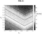
- FIG. 6 the largest line voltage among vAN, vBN, vCN according to k1 and k2 is expressed as in FIG. 6.
- FIG. 6 is a view illustrating a maximum value of line voltages, vAN, vBN, vCN, according to k1 and k2 of the motor driving apparatus in accordance with one embodiment of the present disclosure.
- FIG. 6 is obtained by changing k1 and k2 of formula 6, 7, and 8 into a two-dimensional form.
- FIG. 6 is represented by contour lines so that the three-dimensional value according to ki/k2 is expressed on a two-dimensional form.
- the lower left side represents higher voltage and the right side represents relatively lower voltage.
- the color-coded voltage levels according to the left side graph is expressed in a shape of a strip.
- one of the first PMSM 152 and the second PMSM 154 may be driven while one of the first PMSM 152 and the second PMSM 154 is not driven.
- the abc current command ia1 *, ib1 *, ic1 *, ia2 *, ib2 *, ic2 * is represented as the time function, when current of formula 4 flow on the first PMSM 152 and current of formula 5 are all zero, ic1 of the first PMSM 152 may separately flow on a-phase and b-phase of the second PMSM 154 according to k1 and k2.
- FIGS. 7 , 8 and 9 are views illustrating simulation results of the motor driving apparatus in accordance with an embodiment of the present disclosure.
- Each of the simulation conditions in FIGS. 7 , 8 and 9 are as follows.
- FIG. 7 1200 1200 5 5 0.5 0.5
- FIG. 7 is a view illustrating each speed and phase current of the PMSMs, when two PMSMs are rotated at the same speed.
- each speed command of the two PMSM is 1200 rpm, and load torque is 5 N ⁇ m.
- values of k1 and k2 are 0.5 so that the same amount of current is applied to the two PMSMs.
- the speed waveform shown in FIG. 7 the two PMSMs are determined to be rotated at the same speed.
- phase current of the two PMSMs is overlapped and close to zero and the other two phase currents flow with the same ratio, that is, k1 and k2 are 0.5.
- FIG. 8 is a view illustrating each speed and phase current of two PMSMs when the driving speed and starting time are different from each other.
- Each speed command of the two PMSMs is 1200 rpm and 800 rpm, and the load torque is 5 N ⁇ m. Under this condition, values of k1 and k2 are 0.62 and 1 respectively.
- the second motor is driven, at approximately 0.1s, referring to FIG. 8 , the speed of the first motor Wrpm1 is momentarily reduced, but is restored to the level of 1200 rpm and follows the speed command of 1200 rpm.
- FIG. 8 the speed of the first motor Wrpm1 is momentarily reduced, but is restored to the level of 1200 rpm and follows the speed command of 1200 rpm.
- the other PMSM may be driven, Wrpm1.
- Two PMSM may be driven at different speed from each other so that even when each rotator position of the two PMSMs are different from each other the two PMSMs may be controlled.
- FIG. 9 is a view illustrating each speed and phase current of two PMSMs when the driving speed and the load torque are different from each other.
- Each speed command of the two PMSM is 1200 rpm and 800 rpm, and the load torque is 5 N ⁇ m and 3 N ⁇ m.
- the two PMSMs may be driven at predetermined speed with a predetermined load torque.
- FIG. 10 is a flowchart of a method of connecting a power conversion apparatus to a plurality of motors to supply power to the motors, according to an example.
- the plurality of motors may include a first motor and a second motor.
- a connection method may be used to connect the power conversion apparatus to the first motor and the second motor to supply power from to the first motor and the second motor.
- the power conversion apparatus may be provided with a DC link and a single inverter as described above with reference to FIGS. 1 through 9 .
- a first leg of the single inverter may be connected to a first coil of the first motor.
- a second leg of the single inverter may be connected to a second coil of the first motor.
- a third leg of the single inverter may be connected to the first coil of the second motor.
- a neutral point of the DC link may be connected to the second coil of the second motor.
- a third coil of the first motor may be connected to a third coil of the second motor.
- current applied through the connection between the first leg of the single inverter and the first coil of the first motor may be detected by a first current sensor.
- current applied through the connection between the second leg of the single inverter and the second coil of the first motor may be detected by a second current sensor.
- current applied through the connection between the third leg of the single inverter and the first coil of the second motor may be detected by a third current sensor.
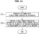
- FIG. 11 is a flowchart of a method of driving a plurality of motors using a single power conversion apparatus, according to an example.
- a single power conversion apparatus is used to generate AC power.
- the single power conversion apparatus is controlled to adjust the phase current ratio supplied from a single power conversion apparatus to each of a plurality of motors according to a power requirement of each of the plurality of motors, which are driven by receiving the generated AC power from the power conversion apparatus.
- FIG. 12 is a flowchart of a method of driving a plurality of motors using a single power conversion apparatus, according to an example.
- a single power conversion apparatus is used to generate AC power.
- the power conversion apparatus is controlled to adjust a phase current ratio supplied from the single power conversion apparatus so that line voltage at a node, at which the single power conversion apparatus and the plurality of motors are connected, is at a minimum.
- the methods according to the above-described examples may be recorded in non-transitory computer-readable media including program instructions to implement various operations embodied by a computer.
- the media may also include, alone or in combination with the program instructions, data files, data structures, and the like.
- the program instructions recorded on the media may be those specially designed and constructed for the purposes of the example embodiments, or they may be of the kind well-known and available to those having skill in the computer software arts.
- the media may also include, alone or in combination with the program instructions, data files, data structures, and the like.
- non-transitory computer-readable media include magnetic media such as hard disks, floppy disks, and magnetic tape; optical media such as CD ROM discs and DVDs; magneto-optical media such as optical discs; and hardware devices that are specially configured to store and perform program instructions, such as read-only memory (ROM), random access memory (RAM), flash memory, and the like.
- magnetic media such as hard disks, floppy disks, and magnetic tape
- optical media such as CD ROM discs and DVDs
- magneto-optical media such as optical discs
- hardware devices that are specially configured to store and perform program instructions, such as read-only memory (ROM), random access memory (RAM), flash memory, and the like.
- Examples of program instructions include both machine code, such as produced by a compiler, and files containing higher level code that may be executed by the computer using an interpreter.
- the described hardware devices may be configured to act as one or more software modules in order to perform the operations of the above-described embodiments, or vice versa.
- Any one or more of the software modules described herein may be executed by a dedicated hardware-based computer or processor unique to that unit or by a hardware-based computer or processor common to one or more of the modules.
- the described methods may be executed on a general purpose computer or processor or may be executed on a particular machine such as the apparatusses described herein.
Applications Claiming Priority (1)
| Application Number | Priority Date | Filing Date | Title |
|---|---|---|---|
| KR1020140017763A KR102272044B1 (ko) | 2014-02-17 | 2014-02-17 | 단일 인버터를 이용한 복수의 영구 자석 동기식 모터의 구동 장치 및 방법 |
Publications (3)
| Publication Number | Publication Date |
|---|---|
| EP2908425A2 EP2908425A2 (en) | 2015-08-19 |
| EP2908425A3 EP2908425A3 (en) | 2015-09-09 |
| EP2908425B1 true EP2908425B1 (en) | 2019-04-03 |
Family
ID=52469767
Family Applications (1)
| Application Number | Title | Priority Date | Filing Date |
|---|---|---|---|
| EP15155482.1A Active EP2908425B1 (en) | 2014-02-17 | 2015-02-17 | Apparatus for driving a plurality of permanent magnet synchronous motors using single inverter |
Country Status (3)
| Country | Link |
|---|---|
| US (1) | US9768715B2 (ko) |
| EP (1) | EP2908425B1 (ko) |
| KR (1) | KR102272044B1 (ko) |
Families Citing this family (17)
| Publication number | Priority date | Publication date | Assignee | Title |
|---|---|---|---|---|
| KR102166362B1 (ko) * | 2013-12-18 | 2020-10-15 | 오티스 엘리베이터 컴파니 | 다중-레벨 회생 드라이브를 위한 버스 커패시터 뱅크 구성 |
| KR101687556B1 (ko) * | 2015-08-31 | 2016-12-19 | 엘지전자 주식회사 | 모터 구동장치 및 이를 구비하는 홈 어플라이언스 |
| JP6230677B1 (ja) * | 2016-10-20 | 2017-11-15 | 三菱電機株式会社 | 回転電機の制御装置および制御方法 |
| US10717401B2 (en) * | 2017-04-21 | 2020-07-21 | Ford Global Technologies, Llc | Terminal block assembly for electrified vehicles |
| WO2019042568A1 (en) * | 2017-09-01 | 2019-03-07 | Electrolux Appliances Aktiebolag | WASHING MACHINE FOR WASHING ARTICLES EQUIPPED WITH AN ELECTRIC DRIVE UNIT FOR OPERATING ELECTRIC MOTORS |
| DE102017125317A1 (de) * | 2017-10-27 | 2019-05-02 | Ebm-Papst Mulfingen Gmbh & Co. Kg | Mehrmotorenbetrieb |
| DE102018103527A1 (de) * | 2018-02-16 | 2019-08-22 | Lloyd Dynamowerke Gmbh | Walzenschrämlader sowie eine Schrämwalze eines Walzenschrämladers |
| KR102137791B1 (ko) * | 2019-01-11 | 2020-07-24 | (주)에이엠케이 | 비엘디씨 모터 |
| CN113273077B (zh) * | 2019-01-16 | 2023-11-14 | 三菱电机株式会社 | 马达控制装置以及空气调和装置 |
| JP6704560B1 (ja) * | 2019-03-18 | 2020-06-03 | 三菱電機株式会社 | 電力変換装置、駆動制御システム、機械学習装置、およびモータ監視方法 |
| WO2020188693A1 (ja) * | 2019-03-18 | 2020-09-24 | 三菱電機株式会社 | 電力変換装置およびモータ監視方法 |
| AU2020202160B2 (en) * | 2019-03-26 | 2021-12-23 | Lg Electronics Inc. | Motor driving device including single inverter for single-phase motor and three-phases motor and appliance having the same |
| KR20210053687A (ko) | 2019-11-04 | 2021-05-12 | 엘지전자 주식회사 | 복수 모터 구동장치 및 이를 구비하는 전기 기기 |
| CN115298559A (zh) * | 2020-03-20 | 2022-11-04 | 麦格纳国际公司 | 用于永磁同步马达的永磁磁链确定 |
| CN112196896B (zh) * | 2020-10-10 | 2021-11-19 | 珠海格力电器股份有限公司 | 一种磁悬浮控制方法、系统、控制器及存储介质 |
| KR102442866B1 (ko) * | 2020-10-12 | 2022-09-15 | 영남대학교 산학협력단 | 복수의 pmsm을 병렬 구동하는 인버터 시스템 |
| US20230327583A1 (en) * | 2022-04-08 | 2023-10-12 | Abb Schweiz Ag | Parallel synchronous machines with single motor drive |
Family Cites Families (4)
| Publication number | Priority date | Publication date | Assignee | Title |
|---|---|---|---|---|
| JP4856493B2 (ja) * | 2006-08-07 | 2012-01-18 | 本田技研工業株式会社 | 2モータ同時駆動システム、およびその制御装置 |
| DE102007030072A1 (de) * | 2007-06-29 | 2009-01-02 | BSH Bosch und Siemens Hausgeräte GmbH | Elektrischen Antriebseinrichtung für ein Wasserführendes Haushaltsgerät |
| WO2012059962A1 (ja) * | 2010-11-05 | 2012-05-10 | 川崎重工業株式会社 | 電動車両の動力装置 |
| EP2755320B1 (en) * | 2011-09-08 | 2018-06-06 | Mitsubishi Electric Corporation | Overtemperature protection device for motor |
-
2014
- 2014-02-17 KR KR1020140017763A patent/KR102272044B1/ko active IP Right Grant
-
2015
- 2015-02-17 EP EP15155482.1A patent/EP2908425B1/en active Active
- 2015-02-18 US US14/624,836 patent/US9768715B2/en active Active
Non-Patent Citations (1)
| Title |
|---|
| None * |
Also Published As
| Publication number | Publication date |
|---|---|
| US20150236625A1 (en) | 2015-08-20 |
| KR102272044B1 (ko) | 2021-07-05 |
| US9768715B2 (en) | 2017-09-19 |
| KR20150096900A (ko) | 2015-08-26 |
| EP2908425A2 (en) | 2015-08-19 |
| EP2908425A3 (en) | 2015-09-09 |
Similar Documents
| Publication | Publication Date | Title |
|---|---|---|
| EP2908425B1 (en) | Apparatus for driving a plurality of permanent magnet synchronous motors using single inverter | |
| US8232753B2 (en) | Control device for electric motor drive apparatus | |
| US10199979B2 (en) | Power conversion device | |
| JP6194113B2 (ja) | モータ駆動装置 | |
| WO2019142877A1 (ja) | 回転電機制御装置 | |
| US20130334937A1 (en) | Rotary electric machine driving system | |
| WO2017141513A1 (ja) | 電力変換装置 | |
| US11705832B2 (en) | Device for driving a plurality of motors and electric apparatus including the same | |
| Hua et al. | Improved model‐predictive‐flux‐control strategy for three‐phase four‐switch inverter‐fed flux‐reversal permanent magnet machine drives | |
| JP2008220117A (ja) | 交流電動機の制御装置 | |
| Mink et al. | Feedback control of high-speed PMSM with synchronous optimal PWM | |
| JP2015109777A (ja) | モータ制御装置 | |
| US10868488B2 (en) | Six-wire three-phase motor, inverter device, and motor system | |
| WO2017030055A1 (ja) | 回転機の制御装置および制御方法 | |
| JP6287636B2 (ja) | 回転機の制御装置 | |
| US11909342B2 (en) | Rotating electrical machine control device | |
| JP6203418B2 (ja) | 電力変換装置およびその制御方法、電動パワーステアリングの制御装置 | |
| CN116648849A (zh) | 旋转电机控制系统 | |
| JP2017175824A (ja) | インバータ制御装置およびインバータ制御方法 | |
| JP6951945B2 (ja) | モータ制御装置及びモータ制御方法 | |
| JP6681266B2 (ja) | 電動機の制御装置及びそれを備えた電動車両 | |
| Prakash et al. | Field oriented control of an open end winding induction machine with zero common mode voltage | |
| WO2023233682A1 (ja) | 交流回転電機の制御装置 | |
| JP6854850B2 (ja) | 電流検出装置および電流検出装置の製造方法 | |
| Khather | Modeling and simulation of a PWM rectifier inverter induction motor drive system implementing speed sensor less direct vector control |
Legal Events
| Date | Code | Title | Description |
|---|---|---|---|
| PUAL | Search report despatched |
Free format text: ORIGINAL CODE: 0009013 |
|
| PUAI | Public reference made under article 153(3) epc to a published international application that has entered the european phase |
Free format text: ORIGINAL CODE: 0009012 |
|
| AK | Designated contracting states |
Kind code of ref document: A2 Designated state(s): AL AT BE BG CH CY CZ DE DK EE ES FI FR GB GR HR HU IE IS IT LI LT LU LV MC MK MT NL NO PL PT RO RS SE SI SK SM TR |
|
| AX | Request for extension of the european patent |
Extension state: BA ME |
|
| AK | Designated contracting states |
Kind code of ref document: A3 Designated state(s): AL AT BE BG CH CY CZ DE DK EE ES FI FR GB GR HR HU IE IS IT LI LT LU LV MC MK MT NL NO PL PT RO RS SE SI SK SM TR |
|
| AX | Request for extension of the european patent |
Extension state: BA ME |
|
| RIC1 | Information provided on ipc code assigned before grant |
Ipc: H02P 21/00 20060101ALI20150805BHEP Ipc: H02P 6/04 20060101ALI20150805BHEP Ipc: H02P 5/74 20060101AFI20150805BHEP |
|
| 17P | Request for examination filed |
Effective date: 20160309 |
|
| RBV | Designated contracting states (corrected) |
Designated state(s): AL AT BE BG CH CY CZ DE DK EE ES FI FR GB GR HR HU IE IS IT LI LT LU LV MC MK MT NL NO PL PT RO RS SE SI SK SM TR |
|
| GRAP | Despatch of communication of intention to grant a patent |
Free format text: ORIGINAL CODE: EPIDOSNIGR1 |
|
| STAA | Information on the status of an ep patent application or granted ep patent |
Free format text: STATUS: GRANT OF PATENT IS INTENDED |
|
| RIC1 | Information provided on ipc code assigned before grant |
Ipc: H02P 21/22 20160101ALI20180713BHEP Ipc: H02P 5/74 20060101AFI20180713BHEP Ipc: H02P 6/04 20060101ALI20180713BHEP |
|
| INTG | Intention to grant announced |
Effective date: 20180803 |
|
| GRAJ | Information related to disapproval of communication of intention to grant by the applicant or resumption of examination proceedings by the epo deleted |
Free format text: ORIGINAL CODE: EPIDOSDIGR1 |
|
| STAA | Information on the status of an ep patent application or granted ep patent |
Free format text: STATUS: REQUEST FOR EXAMINATION WAS MADE |
|
| GRAR | Information related to intention to grant a patent recorded |
Free format text: ORIGINAL CODE: EPIDOSNIGR71 |
|
| GRAS | Grant fee paid |
Free format text: ORIGINAL CODE: EPIDOSNIGR3 |
|
| STAA | Information on the status of an ep patent application or granted ep patent |
Free format text: STATUS: GRANT OF PATENT IS INTENDED |
|
| INTC | Intention to grant announced (deleted) | ||
| RAP1 | Party data changed (applicant data changed or rights of an application transferred) |
Owner name: SAMSUNG ELECTRONICS CO., LTD. Owner name: SEOUL NATIONAL UNIVERSITY R&DB FOUNDATION |
|
| RIC1 | Information provided on ipc code assigned before grant |
Ipc: H02P 6/04 20160101ALI20180713BHEP Ipc: H02P 5/74 20060101AFI20180713BHEP Ipc: H02P 21/22 20160101ALI20180713BHEP |
|
| INTG | Intention to grant announced |
Effective date: 20190115 |
|
| GRAA | (expected) grant |
Free format text: ORIGINAL CODE: 0009210 |
|
| STAA | Information on the status of an ep patent application or granted ep patent |
Free format text: STATUS: THE PATENT HAS BEEN GRANTED |
|
| AK | Designated contracting states |
Kind code of ref document: B1 Designated state(s): AL AT BE BG CH CY CZ DE DK EE ES FI FR GB GR HR HU IE IS IT LI LT LU LV MC MK MT NL NO PL PT RO RS SE SI SK SM TR |
|
| REG | Reference to a national code |
Ref country code: GB Ref legal event code: FG4D |
|
| REG | Reference to a national code |
Ref country code: CH Ref legal event code: EP Ref country code: AT Ref legal event code: REF Ref document number: 1116989 Country of ref document: AT Kind code of ref document: T Effective date: 20190415 |
|
| REG | Reference to a national code |
Ref country code: DE Ref legal event code: R096 Ref document number: 602015027421 Country of ref document: DE |
|
| REG | Reference to a national code |
Ref country code: IE Ref legal event code: FG4D |
|
| REG | Reference to a national code |
Ref country code: NL Ref legal event code: MP Effective date: 20190403 |
|
| REG | Reference to a national code |
Ref country code: LT Ref legal event code: MG4D |
|
| REG | Reference to a national code |
Ref country code: AT Ref legal event code: MK05 Ref document number: 1116989 Country of ref document: AT Kind code of ref document: T Effective date: 20190403 |
|
| PG25 | Lapsed in a contracting state [announced via postgrant information from national office to epo] |
Ref country code: NL Free format text: LAPSE BECAUSE OF FAILURE TO SUBMIT A TRANSLATION OF THE DESCRIPTION OR TO PAY THE FEE WITHIN THE PRESCRIBED TIME-LIMIT Effective date: 20190403 |
|
| PG25 | Lapsed in a contracting state [announced via postgrant information from national office to epo] |
Ref country code: AL Free format text: LAPSE BECAUSE OF FAILURE TO SUBMIT A TRANSLATION OF THE DESCRIPTION OR TO PAY THE FEE WITHIN THE PRESCRIBED TIME-LIMIT Effective date: 20190403 Ref country code: ES Free format text: LAPSE BECAUSE OF FAILURE TO SUBMIT A TRANSLATION OF THE DESCRIPTION OR TO PAY THE FEE WITHIN THE PRESCRIBED TIME-LIMIT Effective date: 20190403 Ref country code: PT Free format text: LAPSE BECAUSE OF FAILURE TO SUBMIT A TRANSLATION OF THE DESCRIPTION OR TO PAY THE FEE WITHIN THE PRESCRIBED TIME-LIMIT Effective date: 20190803 Ref country code: SE Free format text: LAPSE BECAUSE OF FAILURE TO SUBMIT A TRANSLATION OF THE DESCRIPTION OR TO PAY THE FEE WITHIN THE PRESCRIBED TIME-LIMIT Effective date: 20190403 Ref country code: NO Free format text: LAPSE BECAUSE OF FAILURE TO SUBMIT A TRANSLATION OF THE DESCRIPTION OR TO PAY THE FEE WITHIN THE PRESCRIBED TIME-LIMIT Effective date: 20190703 Ref country code: FI Free format text: LAPSE BECAUSE OF FAILURE TO SUBMIT A TRANSLATION OF THE DESCRIPTION OR TO PAY THE FEE WITHIN THE PRESCRIBED TIME-LIMIT Effective date: 20190403 Ref country code: CZ Free format text: LAPSE BECAUSE OF FAILURE TO SUBMIT A TRANSLATION OF THE DESCRIPTION OR TO PAY THE FEE WITHIN THE PRESCRIBED TIME-LIMIT Effective date: 20190403 Ref country code: LT Free format text: LAPSE BECAUSE OF FAILURE TO SUBMIT A TRANSLATION OF THE DESCRIPTION OR TO PAY THE FEE WITHIN THE PRESCRIBED TIME-LIMIT Effective date: 20190403 Ref country code: HR Free format text: LAPSE BECAUSE OF FAILURE TO SUBMIT A TRANSLATION OF THE DESCRIPTION OR TO PAY THE FEE WITHIN THE PRESCRIBED TIME-LIMIT Effective date: 20190403 |
|
| PG25 | Lapsed in a contracting state [announced via postgrant information from national office to epo] |
Ref country code: RS Free format text: LAPSE BECAUSE OF FAILURE TO SUBMIT A TRANSLATION OF THE DESCRIPTION OR TO PAY THE FEE WITHIN THE PRESCRIBED TIME-LIMIT Effective date: 20190403 Ref country code: PL Free format text: LAPSE BECAUSE OF FAILURE TO SUBMIT A TRANSLATION OF THE DESCRIPTION OR TO PAY THE FEE WITHIN THE PRESCRIBED TIME-LIMIT Effective date: 20190403 Ref country code: GR Free format text: LAPSE BECAUSE OF FAILURE TO SUBMIT A TRANSLATION OF THE DESCRIPTION OR TO PAY THE FEE WITHIN THE PRESCRIBED TIME-LIMIT Effective date: 20190704 Ref country code: BG Free format text: LAPSE BECAUSE OF FAILURE TO SUBMIT A TRANSLATION OF THE DESCRIPTION OR TO PAY THE FEE WITHIN THE PRESCRIBED TIME-LIMIT Effective date: 20190703 Ref country code: LV Free format text: LAPSE BECAUSE OF FAILURE TO SUBMIT A TRANSLATION OF THE DESCRIPTION OR TO PAY THE FEE WITHIN THE PRESCRIBED TIME-LIMIT Effective date: 20190403 |
|
| PG25 | Lapsed in a contracting state [announced via postgrant information from national office to epo] |
Ref country code: IS Free format text: LAPSE BECAUSE OF FAILURE TO SUBMIT A TRANSLATION OF THE DESCRIPTION OR TO PAY THE FEE WITHIN THE PRESCRIBED TIME-LIMIT Effective date: 20190803 Ref country code: AT Free format text: LAPSE BECAUSE OF FAILURE TO SUBMIT A TRANSLATION OF THE DESCRIPTION OR TO PAY THE FEE WITHIN THE PRESCRIBED TIME-LIMIT Effective date: 20190403 |
|
| REG | Reference to a national code |
Ref country code: DE Ref legal event code: R097 Ref document number: 602015027421 Country of ref document: DE |
|
| PG25 | Lapsed in a contracting state [announced via postgrant information from national office to epo] |
Ref country code: DK Free format text: LAPSE BECAUSE OF FAILURE TO SUBMIT A TRANSLATION OF THE DESCRIPTION OR TO PAY THE FEE WITHIN THE PRESCRIBED TIME-LIMIT Effective date: 20190403 Ref country code: EE Free format text: LAPSE BECAUSE OF FAILURE TO SUBMIT A TRANSLATION OF THE DESCRIPTION OR TO PAY THE FEE WITHIN THE PRESCRIBED TIME-LIMIT Effective date: 20190403 Ref country code: RO Free format text: LAPSE BECAUSE OF FAILURE TO SUBMIT A TRANSLATION OF THE DESCRIPTION OR TO PAY THE FEE WITHIN THE PRESCRIBED TIME-LIMIT Effective date: 20190403 Ref country code: SK Free format text: LAPSE BECAUSE OF FAILURE TO SUBMIT A TRANSLATION OF THE DESCRIPTION OR TO PAY THE FEE WITHIN THE PRESCRIBED TIME-LIMIT Effective date: 20190403 |
|
| PLBE | No opposition filed within time limit |
Free format text: ORIGINAL CODE: 0009261 |
|
| STAA | Information on the status of an ep patent application or granted ep patent |
Free format text: STATUS: NO OPPOSITION FILED WITHIN TIME LIMIT |
|
| PG25 | Lapsed in a contracting state [announced via postgrant information from national office to epo] |
Ref country code: SM Free format text: LAPSE BECAUSE OF FAILURE TO SUBMIT A TRANSLATION OF THE DESCRIPTION OR TO PAY THE FEE WITHIN THE PRESCRIBED TIME-LIMIT Effective date: 20190403 Ref country code: IT Free format text: LAPSE BECAUSE OF FAILURE TO SUBMIT A TRANSLATION OF THE DESCRIPTION OR TO PAY THE FEE WITHIN THE PRESCRIBED TIME-LIMIT Effective date: 20190403 |
|
| 26N | No opposition filed |
Effective date: 20200106 |
|
| PG25 | Lapsed in a contracting state [announced via postgrant information from national office to epo] |
Ref country code: TR Free format text: LAPSE BECAUSE OF FAILURE TO SUBMIT A TRANSLATION OF THE DESCRIPTION OR TO PAY THE FEE WITHIN THE PRESCRIBED TIME-LIMIT Effective date: 20190403 |
|
| PG25 | Lapsed in a contracting state [announced via postgrant information from national office to epo] |
Ref country code: SI Free format text: LAPSE BECAUSE OF FAILURE TO SUBMIT A TRANSLATION OF THE DESCRIPTION OR TO PAY THE FEE WITHIN THE PRESCRIBED TIME-LIMIT Effective date: 20190403 |
|
| REG | Reference to a national code |
Ref country code: CH Ref legal event code: PL |
|
| REG | Reference to a national code |
Ref country code: BE Ref legal event code: MM Effective date: 20200229 |
|
| PG25 | Lapsed in a contracting state [announced via postgrant information from national office to epo] |
Ref country code: LU Free format text: LAPSE BECAUSE OF NON-PAYMENT OF DUE FEES Effective date: 20200217 Ref country code: MC Free format text: LAPSE BECAUSE OF FAILURE TO SUBMIT A TRANSLATION OF THE DESCRIPTION OR TO PAY THE FEE WITHIN THE PRESCRIBED TIME-LIMIT Effective date: 20190403 |
|
| PG25 | Lapsed in a contracting state [announced via postgrant information from national office to epo] |
Ref country code: LI Free format text: LAPSE BECAUSE OF NON-PAYMENT OF DUE FEES Effective date: 20200229 Ref country code: CH Free format text: LAPSE BECAUSE OF NON-PAYMENT OF DUE FEES Effective date: 20200229 |
|
| PG25 | Lapsed in a contracting state [announced via postgrant information from national office to epo] |
Ref country code: FR Free format text: LAPSE BECAUSE OF NON-PAYMENT OF DUE FEES Effective date: 20200229 Ref country code: IE Free format text: LAPSE BECAUSE OF NON-PAYMENT OF DUE FEES Effective date: 20200217 |
|
| PG25 | Lapsed in a contracting state [announced via postgrant information from national office to epo] |
Ref country code: BE Free format text: LAPSE BECAUSE OF NON-PAYMENT OF DUE FEES Effective date: 20200229 |
|
| PG25 | Lapsed in a contracting state [announced via postgrant information from national office to epo] |
Ref country code: MT Free format text: LAPSE BECAUSE OF FAILURE TO SUBMIT A TRANSLATION OF THE DESCRIPTION OR TO PAY THE FEE WITHIN THE PRESCRIBED TIME-LIMIT Effective date: 20190403 Ref country code: CY Free format text: LAPSE BECAUSE OF FAILURE TO SUBMIT A TRANSLATION OF THE DESCRIPTION OR TO PAY THE FEE WITHIN THE PRESCRIBED TIME-LIMIT Effective date: 20190403 |
|
| PG25 | Lapsed in a contracting state [announced via postgrant information from national office to epo] |
Ref country code: MK Free format text: LAPSE BECAUSE OF FAILURE TO SUBMIT A TRANSLATION OF THE DESCRIPTION OR TO PAY THE FEE WITHIN THE PRESCRIBED TIME-LIMIT Effective date: 20190403 |
|
| PGFP | Annual fee paid to national office [announced via postgrant information from national office to epo] |
Ref country code: GB Payment date: 20230119 Year of fee payment: 9 Ref country code: DE Payment date: 20230119 Year of fee payment: 9 |
|
| PGFP | Annual fee paid to national office [announced via postgrant information from national office to epo] |
Ref country code: DE Payment date: 20240122 Year of fee payment: 10 Ref country code: GB Payment date: 20240122 Year of fee payment: 10 |