EP2907609A2 - Appareil pour manipuler des objets de section tubulaire et ronde - Google Patents
Appareil pour manipuler des objets de section tubulaire et ronde Download PDFInfo
- Publication number
- EP2907609A2 EP2907609A2 EP15151565.7A EP15151565A EP2907609A2 EP 2907609 A2 EP2907609 A2 EP 2907609A2 EP 15151565 A EP15151565 A EP 15151565A EP 2907609 A2 EP2907609 A2 EP 2907609A2
- Authority
- EP
- European Patent Office
- Prior art keywords
- tool unit
- bearing
- workpiece
- frame element
- threaded shaft
- Prior art date
- Legal status (The legal status is an assumption and is not a legal conclusion. Google has not performed a legal analysis and makes no representation as to the accuracy of the status listed.)
- Withdrawn
Links
Images


Classifications
-
- B—PERFORMING OPERATIONS; TRANSPORTING
- B23—MACHINE TOOLS; METAL-WORKING NOT OTHERWISE PROVIDED FOR
- B23Q—DETAILS, COMPONENTS, OR ACCESSORIES FOR MACHINE TOOLS, e.g. ARRANGEMENTS FOR COPYING OR CONTROLLING; MACHINE TOOLS IN GENERAL CHARACTERISED BY THE CONSTRUCTION OF PARTICULAR DETAILS OR COMPONENTS; COMBINATIONS OR ASSOCIATIONS OF METAL-WORKING MACHINES, NOT DIRECTED TO A PARTICULAR RESULT
- B23Q3/00—Devices holding, supporting, or positioning work or tools, of a kind normally removable from the machine
-
- B—PERFORMING OPERATIONS; TRANSPORTING
- B23—MACHINE TOOLS; METAL-WORKING NOT OTHERWISE PROVIDED FOR
- B23D—PLANING; SLOTTING; SHEARING; BROACHING; SAWING; FILING; SCRAPING; LIKE OPERATIONS FOR WORKING METAL BY REMOVING MATERIAL, NOT OTHERWISE PROVIDED FOR
- B23D21/00—Machines or devices for shearing or cutting tubes
- B23D21/04—Tube-severing machines with rotating tool-carrier
-
- B—PERFORMING OPERATIONS; TRANSPORTING
- B23—MACHINE TOOLS; METAL-WORKING NOT OTHERWISE PROVIDED FOR
- B23D—PLANING; SLOTTING; SHEARING; BROACHING; SAWING; FILING; SCRAPING; LIKE OPERATIONS FOR WORKING METAL BY REMOVING MATERIAL, NOT OTHERWISE PROVIDED FOR
- B23D45/00—Sawing machines or sawing devices with circular saw blades or with friction saw discs
- B23D45/12—Sawing machines or sawing devices with circular saw blades or with friction saw discs with a circular saw blade for cutting tubes
- B23D45/126—Sawing machines or sawing devices with circular saw blades or with friction saw discs with a circular saw blade for cutting tubes with the tool turning around the workpieces
-
- B—PERFORMING OPERATIONS; TRANSPORTING
- B23—MACHINE TOOLS; METAL-WORKING NOT OTHERWISE PROVIDED FOR
- B23D—PLANING; SLOTTING; SHEARING; BROACHING; SAWING; FILING; SCRAPING; LIKE OPERATIONS FOR WORKING METAL BY REMOVING MATERIAL, NOT OTHERWISE PROVIDED FOR
- B23D21/00—Machines or devices for shearing or cutting tubes
- B23D21/06—Hand-operated tube-cutters
-
- B—PERFORMING OPERATIONS; TRANSPORTING
- B23—MACHINE TOOLS; METAL-WORKING NOT OTHERWISE PROVIDED FOR
- B23D—PLANING; SLOTTING; SHEARING; BROACHING; SAWING; FILING; SCRAPING; LIKE OPERATIONS FOR WORKING METAL BY REMOVING MATERIAL, NOT OTHERWISE PROVIDED FOR
- B23D45/00—Sawing machines or sawing devices with circular saw blades or with friction saw discs
- B23D45/006—Sawing machines or sawing devices with circular saw blades or with friction saw discs with means to attach the sawing device to the workpiece
-
- B—PERFORMING OPERATIONS; TRANSPORTING
- B23—MACHINE TOOLS; METAL-WORKING NOT OTHERWISE PROVIDED FOR
- B23D—PLANING; SLOTTING; SHEARING; BROACHING; SAWING; FILING; SCRAPING; LIKE OPERATIONS FOR WORKING METAL BY REMOVING MATERIAL, NOT OTHERWISE PROVIDED FOR
- B23D45/00—Sawing machines or sawing devices with circular saw blades or with friction saw discs
- B23D45/12—Sawing machines or sawing devices with circular saw blades or with friction saw discs with a circular saw blade for cutting tubes
-
- B—PERFORMING OPERATIONS; TRANSPORTING
- B23—MACHINE TOOLS; METAL-WORKING NOT OTHERWISE PROVIDED FOR
- B23D—PLANING; SLOTTING; SHEARING; BROACHING; SAWING; FILING; SCRAPING; LIKE OPERATIONS FOR WORKING METAL BY REMOVING MATERIAL, NOT OTHERWISE PROVIDED FOR
- B23D45/00—Sawing machines or sawing devices with circular saw blades or with friction saw discs
- B23D45/16—Hand-held sawing devices with circular saw blades
-
- B—PERFORMING OPERATIONS; TRANSPORTING
- B23—MACHINE TOOLS; METAL-WORKING NOT OTHERWISE PROVIDED FOR
- B23D—PLANING; SLOTTING; SHEARING; BROACHING; SAWING; FILING; SCRAPING; LIKE OPERATIONS FOR WORKING METAL BY REMOVING MATERIAL, NOT OTHERWISE PROVIDED FOR
- B23D47/00—Sawing machines or sawing devices working with circular saw blades, characterised only by constructional features of particular parts
- B23D47/02—Sawing machines or sawing devices working with circular saw blades, characterised only by constructional features of particular parts of frames; of guiding arrangements for work-table or saw-carrier
-
- B—PERFORMING OPERATIONS; TRANSPORTING
- B23—MACHINE TOOLS; METAL-WORKING NOT OTHERWISE PROVIDED FOR
- B23D—PLANING; SLOTTING; SHEARING; BROACHING; SAWING; FILING; SCRAPING; LIKE OPERATIONS FOR WORKING METAL BY REMOVING MATERIAL, NOT OTHERWISE PROVIDED FOR
- B23D47/00—Sawing machines or sawing devices working with circular saw blades, characterised only by constructional features of particular parts
- B23D47/04—Sawing machines or sawing devices working with circular saw blades, characterised only by constructional features of particular parts of devices for feeding, positioning, clamping, or rotating work
-
- B—PERFORMING OPERATIONS; TRANSPORTING
- B23—MACHINE TOOLS; METAL-WORKING NOT OTHERWISE PROVIDED FOR
- B23Q—DETAILS, COMPONENTS, OR ACCESSORIES FOR MACHINE TOOLS, e.g. ARRANGEMENTS FOR COPYING OR CONTROLLING; MACHINE TOOLS IN GENERAL CHARACTERISED BY THE CONSTRUCTION OF PARTICULAR DETAILS OR COMPONENTS; COMBINATIONS OR ASSOCIATIONS OF METAL-WORKING MACHINES, NOT DIRECTED TO A PARTICULAR RESULT
- B23Q7/00—Arrangements for handling work specially combined with or arranged in, or specially adapted for use in connection with, machine tools, e.g. for conveying, loading, positioning, discharging, sorting
-
- B—PERFORMING OPERATIONS; TRANSPORTING
- B25—HAND TOOLS; PORTABLE POWER-DRIVEN TOOLS; MANIPULATORS
- B25B—TOOLS OR BENCH DEVICES NOT OTHERWISE PROVIDED FOR, FOR FASTENING, CONNECTING, DISENGAGING OR HOLDING
- B25B5/00—Clamps
- B25B5/06—Arrangements for positively actuating jaws
- B25B5/10—Arrangements for positively actuating jaws using screws
- B25B5/103—Arrangements for positively actuating jaws using screws with a hinge
-
- B—PERFORMING OPERATIONS; TRANSPORTING
- B23—MACHINE TOOLS; METAL-WORKING NOT OTHERWISE PROVIDED FOR
- B23Q—DETAILS, COMPONENTS, OR ACCESSORIES FOR MACHINE TOOLS, e.g. ARRANGEMENTS FOR COPYING OR CONTROLLING; MACHINE TOOLS IN GENERAL CHARACTERISED BY THE CONSTRUCTION OF PARTICULAR DETAILS OR COMPONENTS; COMBINATIONS OR ASSOCIATIONS OF METAL-WORKING MACHINES, NOT DIRECTED TO A PARTICULAR RESULT
- B23Q2703/00—Work clamping
- B23Q2703/02—Work clamping means
- B23Q2703/10—Devices for clamping workpieces of a particular form or made from a particular material
Definitions
- the invention relates to an apparatus for manipulating, such as machining and especially cutting tubular and round-bar type objects.
- a variety of tools are known from the prior art for machining, such as for cutting a tubular or round-bar type piece.
- One exemplary tool of the prior art is an apparatus comprising a clamping mechanism adapted to be fastened to the workpiece rotatably there around.
- the clamping mechanism has attached thereto a tool unit, which is provided with adjustment means for displacing said tool unit relative to the clamping mechanism towards or away from the workpiece.
- the clamping mechanism included a frame element and first and second arms extending therefrom, the arms being articulated at one end to the frame element of the clamping mechanism and each arm has its free end fitted with a bearing axle, which is provided with at least one bearing wheel.
- the clamping mechanism has its frame element provided in a rotatable and axially immobile fashion with a threaded shaft, whose first end has a right-handed thread provided with a first nut and whose second end has a left-handed thread provided with a second nut.
- the threaded shaft is provided with a member for rotating the threaded shaft, and the first arm and the first nut are articulated to each other by means of a first suspension arm and the second arm and the second nut are articulated to each other by means of a second suspension arm.
- This apparatus has functioned excellently. However the user must concentrate to the machining operation very carefully and press the apparatus against the object during the operation. This is especially the case when machining, such as cutting the workpiece in a certain direction, for example cutting it perpendicularly. This might be in some situations cumbersome and causes danger.
- An object of the invention is to alleviate and eliminate the problems relating to the known prior art. Especially the object of the invention is to provide an apparatus, which can be used more easily and more safety.
- the invention relates to an apparatus according to claim 1.
- the apparatus comprises a locking member which allows the apparatus to be locked in the manipulating position in a releasable manner. This makes the manipulating operation much easier, because the user has not to press the apparatus against the workpiece during the machining process. The locking from the machining position can be easily released when needed.
- the apparatus further comprises two second bearing axles, fitted either fixed manner or adjustably relative to their mutual distance between the arms and the frame element, each of said axles being provided with at least one bearing wheel.
- the working force produced by a blade of the tool unit applies to the workpiece a force, in response to which the workpiece presses against the bearing wheels mounted on said second bearing axles. Consequently, the overall flexures remain as insignificant as possible.
- said second bearing axles are adapted to be adjusted by means of the threaded shaft concurrently with the bearing axles present at the ends of the arms.
- each of said second bearing axles is connected to one of the nuts of the threaded shaft.
- each of said second bearing axles is connected to one of the arms.
- the arrangement is such that at least one of the bearing wheels of the bearing axles is adapted to rotate in one direction only. This arrangement enables preventing a relative rotation of the tool unit and/or the pipe in a wrong direction, which would result in exceptional working forces that could develop flexures, which in turn would have an adverse effect on the resulting cut surface.
- the apparatus is provided also with a lateral adjusting means for adjusting the tool unit in a lateral direction, which is perpendicular in relative to the displacing movement happening towards or away from the workpiece. Accordingly also alignment or track of any saw or blade or other manipulating device of the tool unit is adjusted in a lateral direction in relation to the workpiece, such as a pipe, at the same when the too unit is adjusted. This allows adjusting the travelling direction of the tool unit, as well as especially the track of the manipulating device along the workpiece to be manipulated.
- One example is a track of sawing, when the pipe is sawed.
- the tool unit comprises preferably a circular saw, a bandsaw, or a piercing saw. Also a bevelling saw for machining a bevel with a certain angle, e.g. 30° angle, at the end of the pipe can be used. Additionally the rotation speed of the tool unit is advantageously adjustable depending e.g. on material of the workpiece in question, whereupon the tool unit, saw or blade can be saved for damages. It is to be noted that the tool unit is not limited to those examples only but may also comprise other types of saws or machining means.
- the present invention offers advantages over the known prior art, such as it simplifies and facilitates the manipulating procedure.
- the user does not need to focus to press the apparatus, such as keeping the blade as pressed during the operation due to locking, but he can concentrate to feeding process, such as feeding velocity, which is a clear advantage.
- the invention minimizes also the risks related to concentration of two different tasks, such as pressing and feeding operations.
- the user can concentrate to the feeding velocity and feeding force, it is very advantage for the blade life time, since the smoother the feeding velocity and feeding force, the longer the life time of the blade.
- embodiments of the invention allows also the operation of the apparatus and locking operations with one hand, whereupon the user is free to use the other hand for other possible tasks.
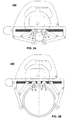
- Figures 1A-1C and 2A-2B illustrate example embodiment of an apparatus 100, 200 according to an advantageous embodiment of the invention for working tubular or round-bar type pieces, such as for cutting a pipe 1.
- a tool unit 3 of the apparatus comprises advantageously a machining blade 13, such as a circular saw.
- the apparatus is designed as a hand tool.
- the apparatus comprises a clamping mechanism 2, which is adapted to be fastened or grip to the pipe 1 to be machined rotatably therearound. Rotation occurs in such a way that the apparatus essentially retains its position in the axial direction of the pipe.
- the clamping mechanism or apparatus comprises advantageously wheels 15, 16, 35, 36 (or any other similarly functioning supporting means, like a slide), which are advantageously mounted with bearings in such a way that, when pressed against the pipe's 1 external surface, the clamping mechanism 2 can be rotated in a plane essentially perpendicular to the centre axis of the pipe 1 or, respectively, the pipe 1 can be rotated relative to the clamping mechanism 2.
- the clamping mechanism 2 is fitted with a tool unit 3, which in the illustrated example comprises a circular saw pivotably mounted by way of an axle 4 to the clamping mechanism 2 for displacing the saw 3 relative to the clamping mechanism 2 towards or away from the pipe 1 (an arrow A, Fig. 1A, 1B ).
- the saw 3 has its blade 13 adapted to operate from outside a common rolling path of the wheels 15, 16, 35, 36.
- the axle 4 is advantageously parallel to the axis of rotation 30 of the blade.
- the clamping mechanism 2 includes a frame element 5, and first and second arms 6, 7 extending therefrom, said arms being articulated at one end thereof to the frame element 5 of the clamping mechanism 2 and the free end of each arm 6, 7.
- the arms 6, 7 are according to an embodiment fitted with a bearing axle 31, 32, on which is mounted at least one bearing wheel 15, 16.
- the apparatus comprises two second bearing axles 33, 34, each of said axles being provided with at least one bearing wheel 35, 36.
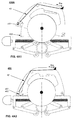
- the second bearing axles 33, 34 might be fitted adjustably (as is the case with Figures 1A-1C ) so that their mutual distance between the arms 6, 7 and the frame element 5 can be changed, or alternatively according to an embodiment they are fixedly fitted to the frame element 5 (as is the case with Figures 2A-2B ).
- each of said second bearing axles 33, 34 (when adjustable) is connected to one of the threaded shaft's 20 nuts 21, 22.
- the second bearing axles 33, 34 are arranged so that the working force developed by the tool unit's 3 blade 13 applies to the workpiece 1 a force, in response to which the workpiece 1 presses against the bearing wheels 35, 36 mounted on said second bearing axles 33, 34.
- Said second bearing axles 33, 34 may be adapted to be adjusted by means of a threaded shaft 20.
- said second bearing axles 33, 34 may be adapted to be adjusted concurrently with the bearing axles 31, 32 present at the ends of the arms 6, 7.
- the clamping mechanism 2 has its frame element 5 fitted rotatably and axially immovably with the threaded shaft 20.
- the threaded shaft 20 has its first end provided with a right-handed thread for a first nut 21 and its second end with a left-handed thread for a second nut 22.
- the threaded shaft 20 is provided with a member 23, in the illustrated example with a turning knob, for rotating the threaded shaft 20.
- the threaded shaft may have in its end a gear system with specific gear ratios for a high-speed movement and an actual engagement.
- first arm 6 and the first nut 21 are articulated to each other by means of a first suspension arm 24.
- second arm 7 and the second nut 22 are articulated to each other by means of a second suspension arm 25.
- second bearing axles 33, 34 are coupled with said suspension arms 24, 25.
- Pivot axles 26, 27 between the arms 6, 7 and the clamping mechanism's 2 frame element 5 are parallel to the bearing axles 31, 32, 33, 34.
- Each bearing axle 31, 32, 33, 34 may carry one or more wheels 15, 16, 35, 36.
- the wheels 15, 16, 35, 36 are arranged pairwise, as depicted in Fig. 1C .
- At least one 15 of the bearing wheels 15, 16, 35, 36 mounted on the bearing axles 31, 32, 33, 34 may be adapted to rotate in one direction only, by means of a per se known ratchet device (having a tongue member 301A and a corresponding gearing 301 B), as is illustrated in Figure 3B .
- a per se known ratchet device having a tongue member 301A and a corresponding gearing 301 B
- This enables a relative rotation of the apparatus and the workpiece 1 in one direction only.
- a wheel enables preventing incorrect operation of the apparatus and deformation possibly caused by adverse cutting forces resulting therefrom and irregularities in the cut surface caused thereby.
- At least one 16 of the bearing wheels 15, 16, 35, 36 may be mounted via an axis 16A on the apparatus in an eccentrically adjustable way (as is depicted in Figure 3A ) so that the track of the apparatus when travelling along the surface of the workpiece to be machined is adjustable.
- the eccentrically adjustable bearing wheel 16 has an outer surface 16C arranged to rotate around a member 16D, which is mounted via the axis 16A.
- the member 16D can be locked in different positions by a locking member 16B. By this one can ensure good quality and direct sawing and seam.
- At least one of the bearing wheels 15, 16, 35, 36 is configured to increase friction of the bearing wheel 15, 16, 35, 36 in the axial direction of the workpiece to be machined and thereby preventing sliding of the wheels and whole apparatus in relative to the workpiece.
- the width of the wheel can be extended and is advantageously at least 2 cm.
- the material of bearing wheel is advantageously chosen so to increase the friction and is for example urethane or rubber.
- the inventive apparatus operates as follows.
- the clamping mechanism 2, along with its saw 3, is laid on top of the pipe 1 at a desired cutting point and the clamping mechanism 2 is fastened thereon by means of the turning knob 23.
- Rotation of the turning knob 23 causes the nut 21 present in the right-handed section of the threaded shaft 20 and the nut 22 present in its left-banded section to move either towards or away from each other, depending on the turning direction.
- Transmitted by the suspension arms 24, 25 and the arms 6, 7, the motion progresses also to the wheels 15, 16, 35, 36, which respectively move either closer to or further away from each other.
- the wheels 15, 16, 35, 36 can thus be brought to press at a desired force against the pipe's 1 external surface.
- the saw 3 can be pivoted towards the pipe 1 relative to the axle 4 included in the frame element 5 of the clamping mechanism 2, whereby the saw's 3 blade penetrates through the pipe's 1 wall to its bottom position, and which is adjustable in a per se known manner. This is followed by circling the clamping mechanism 2, along with its saw 3, around the pipe 1 or, as generally considered more beneficial, the pipe 1 is rotated with the saw 3 remaining stationary until the pipe 1 breaks off.
- the tool unit 3 is arranged in relation to the frame element 5 so that in the machining conditions (i.e. at the moment when the blade is penetrating into the workpiece) the pressing force vector induced via a handgrip of said tool unit 3 intersects an area formed between the first bearing wheel pair 15, 16 or between the second bearing wheel pair 35, 36, most advantageously points towards a midpoint of said tubular or round-bar type piece to be machined.
- any distortion forces can be minimized and additionally usability and ergonomics can be increase.
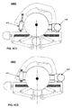
- FIGs 4A1-4F2 illustrate an example of a locking means 400A-400F of the apparatus according to an advantageous embodiment of the invention.
- the locking means 400A is implemented by a hook 402 and corresponding notch 403 to which said hook is configured to be locked when the tool unit 3 is pressed at the machining position ( Fig. 4B ).
- the apparatus 100, 200 is configured to be locked in the manipulating position in a releasable manner, where the releasing is implemented by a releasing means 401, 404 so when actuated, it releases the hook 402 from the notch 403. It is to be noted that this is only an example and the locking function can be implemented also other ways.
- the apparatus may comprise a locking means 400B with number of the notches 403, whereupon the tool unit 3 may be locked in different manipulating positions, as is illustrated in Figures 4B1-4B4 .
- This allows adjusting e.g. the cutting depth or machining angle of the blade used for cutting and thereby enabling longer lifetime for the blade, as well as good quality of the cutting surface.
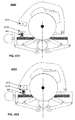
- the locking means 400C may be implemented by a hydraulic or pneumatic cylinder 405 (having advantageously an operating hydraulic or pneumatic pump 406), whereupon the manipulating position of the tool unit, such as a cutting depth, can be adjusted very accurately and in practice continuously, as is illustrated in Figures 4C1-4C2 .
- the locking means 400D may be implemented by using electromagnets 407A, 407B as a locking means.
- the electromagnetic locking means may have own operating switch or alternatively the controlling of the function of the electromagnetic locking means is coupled with the main switch of the apparatus.
- the apparatus may comprise also an adjusting means for setting a limit or manipulating position, such as cutting or machining depth, beforehand.
- One example of the adjusting means is a mechanical blocking member or a screw 408, whereupon the manipulating position of the tool unit can be adjusted by turning the screw.
- the locking may also be implemented by embodiments described in Figures 4E1-4F2 .
- the locking means 400E may be implemented mechanically by a pivot member 409, such as a pin or tap or elongated like member and a corresponding hole 410 as its counterpart, which is configured to lock the tool unit in a certain manipulating position when the pivot member is at least partially inserted into its counterpart 410.
- the locking means 400F may be implemented mechanically by a latch member 411 and a corresponding notch portion 412 being a counterpart for the latch, which is configured to lock the tool unit in a certain manipulating position when the latch member 411 is moved or turned into its counterpart 412.
- both of the apparatus 100, 200 can be provided with any locking means described in this document.
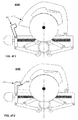
- FIGS 5A-5B illustrate an example of a sawdust managing means 501 of the apparatus according to an advantageous embodiment of the invention, where the sawdust managing means 501 is implemented by a conduit 501 for removing and guiding sawdust (cuttings) produced by a blade 13 of the apparatus during the machining.
- the section 13A of the blade 13 is advantageously arranged to rotate in the portion of said conduit and thereby guiding the sawdust into and from the conduit.
- the apparatus may also comprise an opening and closing means 502 in the connection with the conduit 501 to open and close the conduit and thereby controlling the output of the sawdust from said conduit.
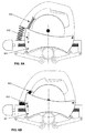
- FIGs 6A-6B illustrate an example of a protection cover 601 for a blade 13 of an apparatus according to an advantageous embodiment of the invention.
- the protection cover 601 is for example a lockable protection means (cover) 601 in the bottom portion of the tool unit so that the locking function is configured to be released for a machining operation.
- the protection cover 601 is configured to be pressed 602 against the workpiece during the machining (see. Fig 5B ) so that the protection cover 601 slides 603 in relation to the tool unit when pressed against the workpiece.
- a spring 602 or the like causes a pressing force, which kept the protection cover 601 against the workpiece during machining.
- a slide 603 is configured to guide the movement of the protection cover 601 during pressing.
- Figures 7A-7C illustrate an example of adjusting means 701, 702, 703, 704 for adjusting the tool 3 unit in a lateral direction according to an advantageous embodiment of the invention, where the lateral direction is perpendicular in relation to the displacing movement happening around the adjustment means 4, which is illustrated e.g. Figures 1A and 1B .
- the lateral adjusting allows controlling and aligning of the travelling direction of the tool unit and the saw or blade or other manipulating means of the tool unit along the workpiece to be manipulated.
- the lateral adjusting means 701, 702, 703, 704 comprises a hinge means 701, around which the lateral adjusting happens.
- the lateral adjusting means comprises a threaded shaft 703 having a finger nut 704 in its first end so that when the finger nut 704 is turned, also the threaded shaft 703 at the same.
- the finger nut is again coupled with the frame element 5.
- the frame element 5 may comprise bracket means arranged around the finger nut 704 so that the finger nut does not essentially move in lateral direction in relation to the frame element 5.
- the threaded shaft 703 is coupled with a coupling means 702 in a fixed manner in its second end.
- the coupling means 702 is again coupled with a tool unit 3 so that when the finger nut 704 and at the same also the threaded shaft 703 is turned, the coupling means 702 displaces the tool unit 3 around hinge means 701 and thereby moving the tool unit 3 laterally in relation to the frame element 5.
- the lateral adjusting means with devices 701, 702, 703, 704 disclosed in Figures 7A-7C is only an example, and that the lateral adjusting can be naturally implemented also with other suitable devices, such as a stepping motor suitable for moving the moving the tool unit 3 with the manipulating means laterally in relation to the frame element, or hook and corresponding notch or number of the notches, hydraulic or pneumatic cylinder, a pivot member, such as a pin or tap or elongated like member and a corresponding hole or holes as its counterpart, or a latch member and a corresponding notch portion or portions being a counterpart for the latch, as an example.
- suitable devices such as a stepping motor suitable for moving the moving the tool unit 3 with the manipulating means laterally in relation to the frame element, or hook and corresponding notch or number of the notches, hydraulic or pneumatic cylinder, a pivot member, such as a pin or tap or elongated like member and a corresponding hole or holes as its counterpart, or a latch member and a corresponding notch portion
- the apparatus is suitable for manipulating, such as especially machining, cutting, bevelling, grooving, welding or otherwise manipulating the tubular and round-bar type pieces.
- the tool unit can also be mounted by the axle 4 to the clamping mechanism 2 in the other end of the apparatus, whereupon the path of the hand when pressing the apparatus might be advantageous in certain embodiment.
Landscapes
- Engineering & Computer Science (AREA)
- Mechanical Engineering (AREA)
- Sawing (AREA)
- Turning (AREA)
- Gripping Jigs, Holding Jigs, And Positioning Jigs (AREA)
- Shearing Machines (AREA)
- Accessories And Tools For Shearing Machines (AREA)
- Jigs For Machine Tools (AREA)
Applications Claiming Priority (1)
| Application Number | Priority Date | Filing Date | Title |
|---|---|---|---|
| FI20145061A FI125718B (en) | 2014-01-22 | 2014-01-22 | A device for treating a tubular or rotary bar |
Publications (2)
| Publication Number | Publication Date |
|---|---|
| EP2907609A2 true EP2907609A2 (fr) | 2015-08-19 |
| EP2907609A3 EP2907609A3 (fr) | 2015-11-11 |
Family
ID=52354818
Family Applications (1)
| Application Number | Title | Priority Date | Filing Date |
|---|---|---|---|
| EP15151565.7A Withdrawn EP2907609A3 (fr) | 2014-01-22 | 2015-01-19 | Appareil pour manipuler des objets de section tubulaire et ronde |
Country Status (9)
| Country | Link |
|---|---|
| US (1) | US20150202699A1 (fr) |
| EP (1) | EP2907609A3 (fr) |
| JP (1) | JP2015136789A (fr) |
| KR (1) | KR20150087820A (fr) |
| CN (2) | CN104842175A (fr) |
| AU (1) | AU2015200262A1 (fr) |
| CA (1) | CA2879265A1 (fr) |
| FI (1) | FI125718B (fr) |
| RU (1) | RU2015101340A (fr) |
Cited By (10)
| Publication number | Priority date | Publication date | Assignee | Title |
|---|---|---|---|---|
| WO2018099747A1 (fr) * | 2016-11-30 | 2018-06-07 | Robert Bosch Gmbh | Bloc hydraulique d'un groupe hydraulique d'une régulation de freinage et procédé de fabrication dudit bloc |
| WO2021058859A1 (fr) * | 2019-09-24 | 2021-04-01 | Exact Tools Oy | Appareil de manipulation d'objets ayant une section tubulaire et ronde |
| US20210114244A1 (en) * | 2018-06-15 | 2021-04-22 | Battenfeld-Cincinnati Germany Gmbh | Device and method for cutting an extruded pipe to length |
| CN113500232A (zh) * | 2021-09-13 | 2021-10-15 | 启东汇斯隆机械有限公司 | 一种船用直梯加工机械手 |
| US11305405B2 (en) | 2017-08-28 | 2022-04-19 | Husqvarna Ab | Cutter clamp, an attachment device, a cutter clamp kit and a holding frame |
| US11691208B2 (en) | 2018-10-27 | 2023-07-04 | Ridge Tool Company | Pipe cut-off tool and accessories for such tools |
| US11697189B2 (en) | 2018-10-05 | 2023-07-11 | Ridge Tool Company | Clamping systems for pipes |
| US11904394B2 (en) | 2018-10-27 | 2024-02-20 | Ridge Tool Company | Interface for powered pipe-working tools |
| US11938650B2 (en) | 2018-10-27 | 2024-03-26 | Ridge Tool Company | Frame grab bars for pipe cut-off tool clamping system |
| US11958208B2 (en) | 2018-10-27 | 2024-04-16 | Ridge Tool Company | Dual blade guard for pipe cut-off tools |
Families Citing this family (32)
| Publication number | Priority date | Publication date | Assignee | Title |
|---|---|---|---|---|
| FI123958B (fi) * | 2010-10-05 | 2014-01-15 | Exact Tools Oy | Laite putkimaisen tai pyörötankomaisen kappaleen työstämiseksi, erityisesti katkaisemiseksi |
| DE102014109150A1 (de) * | 2014-06-30 | 2015-12-31 | Rothenberger Ag | Haltevorrichtung zum verdrehbaren Haltern eines zu bearbeitenden Rohres |
| FI127184B (en) * | 2015-06-23 | 2017-12-29 | Exact Tools Oy | Device for manipulating tubular and circular bodies |
| CN106743540A (zh) * | 2015-11-20 | 2017-05-31 | 华南理工大学 | 一种管材的抱紧运输机械臂 |
| FI20165277A (fi) * | 2016-04-01 | 2017-10-02 | Exact Tools Oy | Laite työstöyksikön tukemiseksi kappaleen manipuloimista varten |
| TWM531342U (zh) * | 2016-07-07 | 2016-11-01 | Lee Yeong Ind Co Ltd | 平鋸機 |
| CN106239336A (zh) * | 2016-08-30 | 2016-12-21 | 卢碧娴 | 新起点金属切割机 |
| JP6072971B1 (ja) * | 2016-09-16 | 2017-02-01 | 株式会社中田製作所 | 管切断機 |
| EP3513894B1 (fr) * | 2016-09-16 | 2021-11-24 | Nakata Manufacturing Co., Ltd. | Machine de coupe de tuyau |
| US10058976B2 (en) * | 2016-11-11 | 2018-08-28 | Att Technology, Ltd. | Hardbanding removal device and method |
| JP6993341B2 (ja) * | 2017-01-20 | 2022-01-13 | 株式会社中田製作所 | 管切断機 |
| US10408091B2 (en) * | 2017-03-31 | 2019-09-10 | General Electric Company | Mounting apparatuses secured to turbine airfoils of turbine systems |
| CN107599085B (zh) * | 2017-10-09 | 2022-10-18 | 庆元县春晓自动化科技有限公司 | 展竹内节钻孔机 |
| WO2019245954A1 (fr) * | 2018-06-18 | 2019-12-26 | Illinois Tool Works Inc. | Système d'usinage de tuyau pour positionner un appareil d'usinage de tuyau dans un système de coordonnées tridimensionnelles |
| PL3778082T3 (pl) * | 2019-08-14 | 2022-08-22 | Smw-Autoblok Spannsysteme Gmbh | Urządzenie mocujące z punktem zerowym |
| CN110450077A (zh) * | 2019-09-12 | 2019-11-15 | 上海精智实业股份有限公司 | 一种对中夹紧装置 |
| CN110814415A (zh) * | 2019-10-17 | 2020-02-21 | 巢湖鹏远金属焊管有限公司 | 一种金属焊管的夹持切割装置 |
| CN111036989A (zh) * | 2019-12-17 | 2020-04-21 | 北京万高众业科技股份有限公司 | 一种气道螺旋线切割装置 |
| CN111112683B (zh) * | 2020-01-02 | 2020-10-27 | 浙江津海机械科技有限公司 | 一种循环流化床锅炉风帽制造加工处理机械 |
| CN111097954B (zh) * | 2020-01-13 | 2021-03-19 | 张贵阳 | 一种方便实用的金属管道切割设备 |
| CN111299696A (zh) * | 2020-03-23 | 2020-06-19 | 东莞市固达机械制造有限公司 | 一种一机多用的圆盘锯床 |
| CN111992797B (zh) * | 2020-08-14 | 2021-07-20 | 邢台职业技术学院 | 一种耐腐钢材料加工设备及加工方法 |
| CN112171744B (zh) * | 2020-10-28 | 2022-02-25 | 江西中浦建材科技有限公司 | 一种信息技术圆形pvc材料切割设备 |
| CN112692761B (zh) * | 2020-12-29 | 2023-11-21 | 霍山嘉远智能制造有限公司 | 一种套筒定位双面加工装置 |
| CN113500248B (zh) * | 2021-09-09 | 2021-11-19 | 南通嘉蒂体育用品有限公司 | 一种安全环保型运动器材加工用切板机 |
| CN114160820B (zh) * | 2021-12-20 | 2022-11-08 | 浙江广厦建设职业技术大学 | 车床加工设备 |
| CN114029637B (zh) * | 2021-12-23 | 2023-11-03 | 武汉誉城千里建工有限公司 | 一种供气管道带压应急抢修用液压开孔设备 |
| CN115647457B (zh) * | 2022-10-31 | 2023-08-08 | 河北北方铸业有限公司 | 用于加工铸钢件的高速切削装置及切削工艺 |
| CN116871587B (zh) * | 2023-09-06 | 2023-11-14 | 江苏兴海特钢有限公司 | 一种手持式管道切割工具 |
| CN117300223B (zh) * | 2023-11-29 | 2024-03-22 | 常州华登液压设备有限公司 | 变量叶片泵加工设备及加工工艺 |
| CN117600547B (zh) * | 2024-01-24 | 2024-04-19 | 江苏迪欧姆股份有限公司 | 精密焊接钢管输送加工设备 |
| CN117943630A (zh) * | 2024-03-27 | 2024-04-30 | 太原正天盖尔机电设备有限公司 | 一种齿轮加工夹紧装置及齿轮加工机床及方法 |
Family Cites Families (3)
| Publication number | Priority date | Publication date | Assignee | Title |
|---|---|---|---|---|
| FI118076B (fi) * | 2003-05-22 | 2007-06-29 | Exact Tools Oy | Laite putkimaisten ja pyörötankomaisten kappaleiden työstämistä, erityisesti katkaisemista varten |
| FI123958B (fi) * | 2010-10-05 | 2014-01-15 | Exact Tools Oy | Laite putkimaisen tai pyörötankomaisen kappaleen työstämiseksi, erityisesti katkaisemiseksi |
| DE202013005723U1 (de) * | 2013-06-26 | 2013-08-01 | Stefan Frank | Trenn- und/oder Abtrennvorrichtung |
-
2014
- 2014-01-22 FI FI20145061A patent/FI125718B/en not_active IP Right Cessation
- 2014-02-13 CN CN201410049517.XA patent/CN104842175A/zh active Pending
-
2015
- 2015-01-19 EP EP15151565.7A patent/EP2907609A3/fr not_active Withdrawn
- 2015-01-19 RU RU2015101340A patent/RU2015101340A/ru not_active Application Discontinuation
- 2015-01-21 CA CA2879265A patent/CA2879265A1/fr not_active Abandoned
- 2015-01-21 US US14/601,577 patent/US20150202699A1/en not_active Abandoned
- 2015-01-21 AU AU2015200262A patent/AU2015200262A1/en not_active Abandoned
- 2015-01-22 KR KR1020150010870A patent/KR20150087820A/ko not_active Application Discontinuation
- 2015-01-22 CN CN201510096156.9A patent/CN104858681A/zh active Pending
- 2015-01-22 JP JP2015010448A patent/JP2015136789A/ja active Pending
Non-Patent Citations (1)
| Title |
|---|
| None |
Cited By (15)
| Publication number | Priority date | Publication date | Assignee | Title |
|---|---|---|---|---|
| US11180129B2 (en) | 2016-11-30 | 2021-11-23 | Robert Bosch Gmbh | Hydraulic block for a hydraulic unit of a brake control system and method for the manufacture thereof |
| CN109982903A (zh) * | 2016-11-30 | 2019-07-05 | 罗伯特·博世有限公司 | 制动调节装置的液压单元用的液压块和制造液压块的方法 |
| KR20190087550A (ko) * | 2016-11-30 | 2019-07-24 | 로베르트 보쉬 게엠베하 | 브레이크 제어부의 유압 유닛용 유압 블록 및 그 제조 방법 |
| WO2018099747A1 (fr) * | 2016-11-30 | 2018-06-07 | Robert Bosch Gmbh | Bloc hydraulique d'un groupe hydraulique d'une régulation de freinage et procédé de fabrication dudit bloc |
| CN109982903B (zh) * | 2016-11-30 | 2022-02-11 | 罗伯特·博世有限公司 | 制动调节装置的液压单元用的液压块和制造液压块的方法 |
| US11305405B2 (en) | 2017-08-28 | 2022-04-19 | Husqvarna Ab | Cutter clamp, an attachment device, a cutter clamp kit and a holding frame |
| US20210114244A1 (en) * | 2018-06-15 | 2021-04-22 | Battenfeld-Cincinnati Germany Gmbh | Device and method for cutting an extruded pipe to length |
| US11697189B2 (en) | 2018-10-05 | 2023-07-11 | Ridge Tool Company | Clamping systems for pipes |
| US11691208B2 (en) | 2018-10-27 | 2023-07-04 | Ridge Tool Company | Pipe cut-off tool and accessories for such tools |
| US11904394B2 (en) | 2018-10-27 | 2024-02-20 | Ridge Tool Company | Interface for powered pipe-working tools |
| US11938650B2 (en) | 2018-10-27 | 2024-03-26 | Ridge Tool Company | Frame grab bars for pipe cut-off tool clamping system |
| US11958208B2 (en) | 2018-10-27 | 2024-04-16 | Ridge Tool Company | Dual blade guard for pipe cut-off tools |
| WO2021058859A1 (fr) * | 2019-09-24 | 2021-04-01 | Exact Tools Oy | Appareil de manipulation d'objets ayant une section tubulaire et ronde |
| CN113500232A (zh) * | 2021-09-13 | 2021-10-15 | 启东汇斯隆机械有限公司 | 一种船用直梯加工机械手 |
| CN113500232B (zh) * | 2021-09-13 | 2021-11-26 | 启东汇斯隆机械有限公司 | 一种船用直梯加工机械手 |
Also Published As
| Publication number | Publication date |
|---|---|
| AU2015200262A1 (en) | 2015-08-06 |
| US20150202699A1 (en) | 2015-07-23 |
| FI20145061A (fi) | 2015-07-23 |
| EP2907609A3 (fr) | 2015-11-11 |
| FI125718B (en) | 2016-01-29 |
| KR20150087820A (ko) | 2015-07-30 |
| CN104858681A (zh) | 2015-08-26 |
| CN104842175A (zh) | 2015-08-19 |
| JP2015136789A (ja) | 2015-07-30 |
| CA2879265A1 (fr) | 2015-07-22 |
| RU2015101340A (ru) | 2016-08-10 |
Similar Documents
| Publication | Publication Date | Title |
|---|---|---|
| EP2907609A2 (fr) | Appareil pour manipuler des objets de section tubulaire et ronde | |
| EP3313601B1 (fr) | Appareil de manipulation d'objets ayant une section tubulaire et ronde | |
| EP1628797B1 (fr) | Appareil d'usinage, destine en particulier a couper des corps de section tubulaire et ronde | |
| US9868164B2 (en) | Apparatus for machining, particularly for cutting a tubular or round section body | |
| KR100955217B1 (ko) | 면취기의 원터치식 면취량 조절장치 | |
| KR100955216B1 (ko) | 원터치식 면취량 조절이 가능한 용접 비드면 가공용 면취기 | |
| US5357714A (en) | Apparatus for shaping the ends of tubular workpieces with recesses of different diameters | |
| US5038473A (en) | Power saw | |
| DE102008015480A1 (de) | Hand-Werkzeugmaschine | |
| WO2017168057A1 (fr) | Appareil pour supporter une unité d'outil pour manipuler une pièce à usiner | |
| US10625438B2 (en) | Metal or wood working equipment with work-piece securing apparatus | |
| EP3132886B1 (fr) | Dispositif rotateur de tube et système permettant de faire tourner des tubes | |
| EP0588515A1 (fr) | Table de scier avec dispositif d'arrêt détachable | |
| KR101687214B1 (ko) | 오토캐리지 | |
| WO2021058859A1 (fr) | Appareil de manipulation d'objets ayant une section tubulaire et ronde | |
| JPH0657398B2 (ja) | 輪切り冷凍魚等の切断装置 | |
| TWM506676U (zh) | 虎鉗 | |
| Bradley | Power saw | |
| JPH0531535A (ja) | ロール溝彫装置 | |
| CA2407368A1 (fr) | Guide d'etabli |
Legal Events
| Date | Code | Title | Description |
|---|---|---|---|
| PUAI | Public reference made under article 153(3) epc to a published international application that has entered the european phase |
Free format text: ORIGINAL CODE: 0009012 |
|
| AK | Designated contracting states |
Kind code of ref document: A2 Designated state(s): AL AT BE BG CH CY CZ DE DK EE ES FI FR GB GR HR HU IE IS IT LI LT LU LV MC MK MT NL NO PL PT RO RS SE SI SK SM TR |
|
| AX | Request for extension of the european patent |
Extension state: BA ME |
|
| PUAL | Search report despatched |
Free format text: ORIGINAL CODE: 0009013 |
|
| AK | Designated contracting states |
Kind code of ref document: A3 Designated state(s): AL AT BE BG CH CY CZ DE DK EE ES FI FR GB GR HR HU IE IS IT LI LT LU LV MC MK MT NL NO PL PT RO RS SE SI SK SM TR |
|
| AX | Request for extension of the european patent |
Extension state: BA ME |
|
| RIC1 | Information provided on ipc code assigned before grant |
Ipc: B23D 45/12 20060101AFI20151005BHEP |
|
| 17P | Request for examination filed |
Effective date: 20160511 |
|
| RBV | Designated contracting states (corrected) |
Designated state(s): AL AT BE BG CH CY CZ DE DK EE ES FI FR GB GR HR HU IE IS IT LI LT LU LV MC MK MT NL NO PL PT RO RS SE SI SK SM TR |
|
| STAA | Information on the status of an ep patent application or granted ep patent |
Free format text: STATUS: THE APPLICATION IS DEEMED TO BE WITHDRAWN |
|
| 18D | Application deemed to be withdrawn |
Effective date: 20170801 |