EP2907222B1 - A rotary device, a motor and a method of cooling a motor - Google Patents
A rotary device, a motor and a method of cooling a motor Download PDFInfo
- Publication number
- EP2907222B1 EP2907222B1 EP13771207.1A EP13771207A EP2907222B1 EP 2907222 B1 EP2907222 B1 EP 2907222B1 EP 13771207 A EP13771207 A EP 13771207A EP 2907222 B1 EP2907222 B1 EP 2907222B1
- Authority
- EP
- European Patent Office
- Prior art keywords
- rotor
- fluid
- coolant
- motor
- impeller
- Prior art date
- Legal status (The legal status is an assumption and is not a legal conclusion. Google has not performed a legal analysis and makes no representation as to the accuracy of the status listed.)
- Active
Links
Images


Classifications
-
- H—ELECTRICITY
- H02—GENERATION; CONVERSION OR DISTRIBUTION OF ELECTRIC POWER
- H02K—DYNAMO-ELECTRIC MACHINES
- H02K1/00—Details of the magnetic circuit
- H02K1/06—Details of the magnetic circuit characterised by the shape, form or construction
- H02K1/22—Rotating parts of the magnetic circuit
- H02K1/27—Rotor cores with permanent magnets
- H02K1/2706—Inner rotors
- H02K1/272—Inner rotors the magnetisation axis of the magnets being perpendicular to the rotor axis
- H02K1/274—Inner rotors the magnetisation axis of the magnets being perpendicular to the rotor axis the rotor consisting of two or more circumferentially positioned magnets
-
- H—ELECTRICITY
- H02—GENERATION; CONVERSION OR DISTRIBUTION OF ELECTRIC POWER
- H02K—DYNAMO-ELECTRIC MACHINES
- H02K1/00—Details of the magnetic circuit
- H02K1/06—Details of the magnetic circuit characterised by the shape, form or construction
- H02K1/22—Rotating parts of the magnetic circuit
- H02K1/32—Rotating parts of the magnetic circuit with channels or ducts for flow of cooling medium
-
- H—ELECTRICITY
- H02—GENERATION; CONVERSION OR DISTRIBUTION OF ELECTRIC POWER
- H02K—DYNAMO-ELECTRIC MACHINES
- H02K1/00—Details of the magnetic circuit
- H02K1/06—Details of the magnetic circuit characterised by the shape, form or construction
- H02K1/22—Rotating parts of the magnetic circuit
- H02K1/27—Rotor cores with permanent magnets
- H02K1/2706—Inner rotors
- H02K1/272—Inner rotors the magnetisation axis of the magnets being perpendicular to the rotor axis
- H02K1/274—Inner rotors the magnetisation axis of the magnets being perpendicular to the rotor axis the rotor consisting of two or more circumferentially positioned magnets
- H02K1/2753—Inner rotors the magnetisation axis of the magnets being perpendicular to the rotor axis the rotor consisting of two or more circumferentially positioned magnets the rotor consisting of magnets or groups of magnets arranged with alternating polarity
- H02K1/278—Surface mounted magnets; Inset magnets
- H02K1/2781—Magnets shaped to vary the mechanical air gap between the magnets and the stator
-
- H—ELECTRICITY
- H02—GENERATION; CONVERSION OR DISTRIBUTION OF ELECTRIC POWER
- H02K—DYNAMO-ELECTRIC MACHINES
- H02K1/00—Details of the magnetic circuit
- H02K1/06—Details of the magnetic circuit characterised by the shape, form or construction
- H02K1/22—Rotating parts of the magnetic circuit
- H02K1/28—Means for mounting or fastening rotating magnetic parts on to, or to, the rotor structures
- H02K1/30—Means for mounting or fastening rotating magnetic parts on to, or to, the rotor structures using intermediate parts, e.g. spiders
-
- H—ELECTRICITY
- H02—GENERATION; CONVERSION OR DISTRIBUTION OF ELECTRIC POWER
- H02K—DYNAMO-ELECTRIC MACHINES
- H02K9/00—Arrangements for cooling or ventilating
- H02K9/19—Arrangements for cooling or ventilating for machines with closed casing and closed-circuit cooling using a liquid cooling medium, e.g. oil
- H02K9/197—Arrangements for cooling or ventilating for machines with closed casing and closed-circuit cooling using a liquid cooling medium, e.g. oil in which the rotor or stator space is fluid-tight, e.g. to provide for different cooling media for rotor and stator
Definitions
- the present invention relates to a rotary device and a motor.
- Electric motors are used widely as a means of generating traction.
- a problem that arises with traction motors is that significant heat can be generated within them. Cooling of the motor is important so as to avoid damage to thermally sensitive components within the motor.
- motors that satisfy this desire can experience more significant heating of the rotor within the motor in normal operation.
- a motor such as a three-phase synchronous motor will typically include both a stator and a rotor.
- the stator is arranged, in use, to receive electrical power so as to generate a varying magnetic field.
- the rotor arranged coaxially within and typically enclosed by the stator, comprises a number of permanent magnets which, under the influence of the varying magnetic field, cause the rotor to rotate.
- a rotational output can be derived.
- the same apparatus can be used in a reverse order to generate electricity. In other words, if the rotor is driven by a rotational drive input, voltage will be generated in the stator coils.
- the remaining heat path for heat loss available to the rotor is via the shaft and bearings. This is typically a poor heat path which does not provide for significant heat transfer, so despite creating less heat by laminating the rotor, the rotor can still easily overheat due to the very poor heat loss mechanisms available.
- stator As hot as possible (high temperature stator materials are relatively inexpensive) and the rotor as cool as possible so as to keep magnet costs to a minimum.
- a rotor assembly cooling system in which a portion of a rotor shaft is hollow and includes an open end and a closed end.
- a coolant feed tube is rigidly attached to the rotor shaft.
- Coolant is pumped through the feed tube until it exits the end of the feed tube and flows against the inside surface of the closed end of the rotor shaft causing the coolant to change direction and flow back through the coolant flow region. Fluid is therefore caused to flow in the space between the outer surface of the feed tube and the inner surface of the hollow rotor shaft.
- a continuous helical member is provided in the form of a continuous support strut which helically wraps around the feed tube and couples it to the shaft. Due to the helical shape of the member, coolant is actively pumped in the region separating the feed tube from the shaft, thus ensuring continuous coolant flow to the rotor assembly.
- US-A-7,489,057 is a related patent to Zhou.
- an oil cooled generator is provided.
- a flow of coolant oil is provided via an opening.
- the coolant oil then flows through helical paths before entering the axial shaft of the generator rotor.
- the fluid passes towards the end of the rotor where it is reflected from the inner surface of the rotor housing and passes back through further helical paths.
- the coolant passes out of the device.
- an oil cooled generator is provided in which the helical path is used to control the flow of cooling oil and in which the fluid feed tube rotates with the rotor.
- fluid-cooled motors or generators include those as described in US-A-4,647,805 , US-A-5,589,720 , WO-A-90/09053 , DE-A-19913199 , US-A-4,692,644 , US-A-8,022,582 , US-A-2001/0308071 , US-A-3,521,094 , US-A-3,060,335 , US-A-3,240,967 , US-A-4,350,908 , US-A-5,424,593 , GB-A-16979 , GB-A-2483122 and DE-A-3622231 .
- DE102009025929 discloses a rotray assembly having an internal bush arranged on shafts of a rotor and being arranged to carry impeller blades.
- An outer bush is formed as a rotor base element, and comprises slots in a longitudinal direction to receive electric sheet packages. Permanent magnets are arranged between the electric sheet packages.
- a rotary device not belonging to the invention, comprising: a stator for receiving or outputting electrical power; a rotor arranged coaxially within the stator and having one or more magnets arranged thereon, the rotor comprising a rotor housing having an inner wall, the magnets being arranged around the housing, and wherein the rotor also comprises conduit having an axial component for the flow of a coolant between a first end of the rotor and a second distal end of the rotor; the rotor further comprising one or more radial fluid conduits, the radial fluid conduits being fluidly coupled to the axial fluid conduit and arranged in use to receive coolant from or provide coolant to the axial fluid conduit, the inner wall having one or more fluid paths for the flow of coolant, thereby to cool the rotor; and a fluid impeller arranged at the first or distal end of rotor and arranged to rotate with the rotor and impart rotary movement to or remove rotary movement from fluid entering or leaving the
- a rotary device not belonging to the invention is provided.
- the rotary device could function as a motor or a generator
- electrical power is provided to the stator which generates a changing magnetic field and causes rotation of the rotor by interaction with the magnets thereon.
- the rotor is driven round which generates power in the stator by virtue of the varying magnetic field to which it is exposed.
- An impeller is provided arranged to rotate with the rotor and impart and/or maintain rotary movement to or remove rotary movement from fluid entering or leaving the rotary device. This means that pressure losses are avoided in cooling fluid flowing through the rotary device.
- An axial fluid conduit is provided which enables fluid to flow in a generally axial direction, i.e.
- the axial fluid conduit is preferably arranged centrally such that fluid can flow through it in a central longitudinal axial position.
- the axial fluid conduit or conduits are arranged at some radial distance from the central longitudinal axis of the rotor.
- a rotary device comprising: a stator for receiving or outputting electrical power; a rotor arranged coaxially within the stator and having one or more magnets arranged thereon, the rotor comprising a rotor housing having an inner wall, the magnets being arranged around the housing, and wherein the rotor also comprises an axial fluid conduit for the flow of a coolant between a first end of the rotor and a second distal end of the rotor; the rotor further comprising one or more radial fluid conduits, the radial fluid conduits being fluidly coupled to the axial fluid conduit and arranged in use to receive coolant from or provide coolant to the axial fluid conduit, the inner wall having one or more tortuous paths for the flow of coolant, thereby to cool the rotor; and a fluid impeller arranged at the first or distal end of rotor and arranged to rotate with the rotor and impart rotary movement to or remove rotary movement from fluid entering
- a rotary device - not belonging to the invention - is provided.
- the rotary device could function as a motor or a generator
- stator As a motor, electrical power is provided to the stator which generates a changing magnetic field and causes rotation of the rotor by interaction with the magnets thereon.
- the rotor In use as a generator, the rotor is driven round which generates power in the stator by virtue of the varying magnetic field to which it is exposed.
- An impeller is provided arranged to rotate with the rotor and impart and/or maintain rotary movement to or remove rotary movement from fluid entering or leaving the rotary device. This means that pressure losses are avoided in cooling fluid flowing through the rotary device.
- One or more tortuous paths are provided on the inner wall for the flow of coolant. These provide a means by which fluid can be made to cover a significant proportion of the surface of the inner thereby ensuring good thermal contact of the fluid with a significant part of the rotor.
- the impeller is arranged to guide the fluid towards the rotor axis for removal from the motor or radially outwardly towards the one or more tortuous paths. This is particularly useful in an example in which fluid flows (in one direction of flow) from an initially central axial position, along the length of the rotor, radially outwards to flow along the tortuous paths and then is brought back in to an axial position.
- the impeller in this example provides a continuous conduit for the fluid whilst not allowing the fluid to flow rotationally relative to the impeller so that when the fluid is brought back to an axial position it has had removed from it its rotational movement. With fluid flowing in the opposite direction the impeller provides a means by which the fluid can be accelerated rotationally without introducing any rotational velocity relative to the rotor.
- the impeller is a unitary moulded component having guide ribs to guide coolant.
- the impeller ribs are curved.
- the impeller ribs are curved with varying curvature.
- the impeller ribs are straight.
- the impeller ribs are formed by drillings, such as cylindrical drillings.
- the coolant enters and leaves the rotor at the same axial end thereof.
- the coolant enters and leaves the rotor axially.
- the coolant enters the rotor axially and leaves the rotor radially.
- the coolant enters the rotor radially and leaves the rotor axially.
- the stator has a labyrinthine path defined therein for the flow of coolant fluid.
- the magnets are staggered or rotationally offset varying with axial displacement along rotor.
- a motor for generating rotary power comprising: a stator for receiving electrical power; a rotor arranged coaxially within the stator and having one or more magnets arranged thereon so that in response to the stator receiving the electrical power, the rotor is caused to rotate, the rotor comprising a rotor housing having an inner wall, the magnets being arranged around the housing, and wherein the rotor also comprises a central fluid conduit for the axial flow of a coolant between a first end of the rotor and a second distal end of the rotor; the rotor further comprising one or more radial fluid conduits at the second distal end of the rotor, the conduits being fluidly coupled to the central fluid conduit and arranged in use to receive coolant from or provide coolant to the central fluid conduit, the inner wall having plural tortuous paths for the flow of coolant, thereby to cool the rotor.
- the rotor has a cylindrical body with one or more tortuous paths arranged thereon.
- the inner wall is cylindrical.
- the rotor Upon application of power to the stator, e.g. application of a voltage to the stator, the rotor is caused to rotate.
- the tortuous paths guide the coolant on the surface of the cylindrical body thus ensuring good coverage of the cylindrical body by the coolant.
- radial fluid conduits are provided to guide the coolant from an axial position within the rotor to the paths on the external surface of the cylindrical body (or in the opposite direction depending on direction of fluid flow). The use of radial conduits in this way ensures that the fluid is delivered conveniently to (or received from) the paths for onward propagation.
- the combination of the radial conduits and the tortuous paths provides an effective and efficient way to enable cooling of the rotor to be achieved. Furthermore, the use of conduits for the fluid ensures that the fluid can be delivered to or received from, the tortuous paths without sudden changes in relative velocity between the rotor parts and the fluid, thus minimising resistance to the flow of coolant.
- One further advantage of the use of radial conduits is that fluid is permitted to be transferred from the central axis to the outside cylinder close to the heat source and back again (or vice versa) with relatively low (if any) pressure loss.
- tortuous paths provided on the surface of the cylindrical body ensure that the fluid flows at relatively high velocity, i.e. higher than it would without the paths.
- relatively high velocity fluid flow means that there is good heat transfer into the fluid.
- tortuous paths rather than straight, narrow paths as a means to generate high velocity can be advantageous in terms of resistance to blockage and required manufacturing tolerances, although straight paths can also be used as discussed below..
- the flow of fluid over the cylindrical surface ensures that the coolant is located close to the source of the heat (the magnets) and so heat transfer from the source is managed efficiently.
- the tortuous paths are defined by guide ribs on or grooves in the inner wall.
- the ribs or grooves are helical.
- the angle of helical ribs or grooves is within a certain range.
- the inner wall is cylindrical such that the rotor housing is hollow.
- the motor comprises a fluid inlet and a fluid outlet, wherein the fluid outlet is at a greater radius than the fluid inlet.
- the number of ribs or grooves is the same as the number of radial fluid conduits.
- the number of ribs or grooves is 4.
- the one or more radial conduits is or are formed as drillings or bores in an end cap fixedly mounted to the inner wall.
- the central fluid conduit and the one or more radial fluid conduits are formed as a unitary component.
- the one or more radial fluid conduits is or are curved.
- the central fluid conduit acts as a rotor shaft and has a first end mounted in a bearing at a first end of rotor and second end mounted in a bearing at a second distal end of the rotor.
- the hollow cylinder comprises a sealed air-filled cavity under a heat transfer zone within the motor.
- the motor comprises a fluid impeller arranged at the first end of rotor to receive coolant from or provide coolant to the spiral ribs and guide the fluid towards the rotor axis for removal from the motor or radially outwardly towards the spiral ribs.
- the impeller is a unitary moulded component having guide ribs to guide coolant.
- the impeller ribs are curved.
- the impeller ribs are curved with varying curvature.
- the impeller ribs are straight.
- the coolant enters and leaves the rotor at the same axial end thereof.
- the coolant enters and leaves the rotor axially.
- the coolant enters the rotor axially and leaves the rotor radially.
- the coolant enters the rotor radially and leaves the rotor axially.
- fluid flow can be provided in any desired direction within the rotor.
- the fluid is provided radially and taken from the rotor after its passage through it, from the same end of the rotor.
- the fluid is provided axially at one end and leaves radially at the other.
- fluid is provided radially at one end and leaves radially at the opposite end. In the example where fluid leaves from a different end from which it is input, it is typically fed directly into the tortuous paths for a single pass down the rotor before it leaves at the second end.
- the stator has a labyrinthine path defined therein for the flow of coolant fluid.
- the magnets are staggered or rotationally offset varying with axial displacement along rotor.
- an electricity generator comprising: a stator having electrical contacts for outputting generated power; a rotor arranged coaxially within the stator and having one or more magnets arranged thereon, the rotor having a drive input for receiving a rotary input so that in response to the rotor being driven, electrical power is generated in the stator; the rotor comprising a housing having an inner wall, the magnets being arranged around the housing, and wherein the rotor also comprises a central fluid conduit for the axial flow of a coolant between a first end of the rotor and a second distal end of the rotor; the rotor further comprising radial fluid conduits at the second distal end of the rotor, fluidly coupled to the central fluid conduit and arranged in use to receive coolant from or provide fluid to the central fluid conduit, the inner wall having plural tortuous paths for the flow of coolant, thereby to cool the rotor.
- a method of cooling a rotor in a motor for generating rotary power comprising: in a motor having a stator for receiving electrical power, a rotor arranged coaxially within the stator and having one or more magnets arranged thereon, providing the rotor with a cylindrical rotor housing having an inner wall, the magnets arranged around the housing, and also providing the rotor with a central fluid conduit for the flow of a coolant axially between a first input end of the rotor and a second distal end of the rotor; and providing the rotor with one or more radial fluid conduits at the second distal end of the rotor, fluidly coupled to the central fluid conduit and arranged in use to receive coolant from or provide coolant to the central fluid conduit, the inner wall having tortuous guide ribs to define plural tortuous paths for the flow of coolant, thereby to cool the rotor.
- the method comprises providing coolant to the central fluid conduit such that the coolant is caused to flow into the radial conduits and along the tortuous paths to cool the rotor.
- a motor for generating rotary power comprising: a stator for receiving electrical power; a rotor arranged coaxially within the stator and having one or more magnets arranged thereon so that in response to the stator receiving the electrical power, the rotor is caused to rotate, the rotor comprising a rotor housing having an inner wall, the magnets being arranged around the housing, and wherein the rotor also comprises a central fluid conduit for the flow of a coolant from a first input end of the rotor axially to a second distal end of the rotor; the rotor further comprising an end member arranged at the second distal end of the rotor having radial fluid conduits fluidly coupled to the central fluid conduit and arranged in use to receive coolant from the central fluid conduit, the inner wall having tortuous guide ribs to define plural tortuous paths for the flow of coolant from the second distal end to the first input end, thereby to cool the rotor.
- the rotor has a cylindrical body with plural tortuous paths arranged thereon.
- the fluid paths could instead be straight and axially aligned in any desired manner. What matters is that the fluid paths cover a significant proportion of the inner wall..
- the rotor Upon application of power to the stator, e.g. application of a voltage to the stator, the rotor is caused to rotate.
- a cylindrical inner wall can be provided and the fluid paths guide the coolant on the surface of the cylindrical body thus ensuring good coverage of the cylindrical body by the coolant.
- the fluid paths cover at least 35%, of the surface of the inner wall. More preferably the fluid paths are arranged to cover a majority of the surface area of the inner wall, e.g. at least 50%, and even more preferably at least 75% of the surface area of the inner wall.
- tortuous paths One convenient way by which such surface coverage can be achieved is with the use of tortuous paths which is therefore preferred.
- the minimum flow rate of fluid within the fluid paths 50 is 0.5m/s.
- radial fluid conduits are provided to guide the coolant from an axial position within the rotor to the paths on the external surface of the cylindrical body.
- the use of radial conduits in this way ensures that the fluid is delivered conveniently to the paths for onward propagation along the cylindrical wall.
- the combination of the radial conduits and the tortuous paths provides an effective and efficient way to enable cooling of the rotor to be achieved.
- the use of conduits for the fluid ensures that the fluid can be delivered to, and returned from the tortuous paths without sudden changes in relative velocity between the rotor parts and the fluid, thus minimising resistance to the flow of coolant.
- One further advantage of the use of radial conduits is that fluid is permitted to be transferred from the central axis to the outside cylinder close to the heat source and back again with relatively low (if any) pressure loss.
- tortuous paths provided on the surface of the cylindrical body ensure that the fluid flows at relatively high velocity, i.e. higher than it would without the paths.
- relatively high velocity fluid flow means that there is good heat transfer into the fluid.
- tortuous paths rather than straight, narrow paths as a means to generate high velocity is advantageous in terms of resistance to blockage and required manufacturing tolerances.
- the flow of fluid over the cylindrical surface ensures that the coolant is located close to the source of the heat (the magnets) and so heat transfer from the source is managed efficiently.
- ribs are provided to define the tortuous paths.
- the ribs are preferably spiral. This ensures that full coverage of the cylindrical surface with coolant can be achieved, which in turn ensures that heat transfer from the rotor can be performed effectively.
- the angle of ribs i.e. the spiral angle with respect to the longitudinal dimension of the rotor is within a defined range so as to ensure good coverage of the rotor cylindrical wall and a fast fluid flow rate for good heat transfer.
- a 4 start helical thread pattern is used, which, together with the width of flow passage or pitch, yields 10 degrees as a helix angle.
- the width and height of passage was determined by the target flow area, which in turn results from a 2m/s target velocity, consistent with good heat transfer without excessive pressure drop.
- a flow area of 48mm 2 is provided.
- Similar cooling performance may be achieved with 3 or 6 radial drillings and a helix angle in the range 5 to 30 degrees.
- the angle of helical ribs or grooves is in the range of 5 to 30 degrees.
- the cylindrical rotor housing is hollow. This is particularly advantageous since it ensures that a rotor can be provided in the motor, wherein the rotor has low inertia and mass. This is important in terms of being able to start and stop the motor, and more generally reduces the required power to accelerate or decelerate the motor.
- the magnets are staggered or rotationally offset varying with axial displacement along rotor. This enables an optimal response to the varying field generated by the coils within the stator and reduces the magnetic-field-induced harmonic distortion in the driving A/C waveform.
- the number of paths or ribs is the same as the number of radial fluid conduits. This enables a one-to-one correspondence to be established between the conduits and the paths which provides for efficient passing of the coolant from the radial conduits to the paths.
- the number of tortuous paths ribs is 4 (the number of ribs will correspond). This provides good coverage of the cylindrical surface of the rotor whilst being easy to manufacture.
- the radial conduits are formed as drillings or bores in the end member.
- central fluid conduit connects to the end member drilling may extend into the central fluid conduit too so as to enable the fluid to leave from the cylindrical outer wall of the central fluid conduit directly into the drillings or bores within the end member.
- the central fluid conduit and end member (including the radial fluid conduits) are formed as a unitary component. This reduces part count of the motor as a whole and ensures good connection between the central fluid conduit and end member.
- the central fluid conduit acts as a rotor shaft and has a first end mounted in bearing at first end of rotor and second end mounted in bearing at distal end, wherein the rotor shaft extends into and is supported by the bearing.
- the hollow cylinder comprises a sealed air-filled cavity.
- the air filled cavity is arranged within the rotor under the heat transfer zone. The use of an air-filled cavity minimises inertia and thereby reduces the power required to start, stop, accelerate or decelerate the motor.
- the motor comprises a fluid impeller arranged at the first end of rotor to receive coolant from the spiral ribs and guide the fluid towards the rotor axis for removal from the motor.
- the impeller is a unitary moulded component having guide ribs to guide coolant. This enables the benefits of the impeller to be achieved with minimal additional part count. It also means that the impeller can in practice be a simple moulded component within the motor assembly.
- the impeller ribs are curved, which provides for a smooth and gentle removal of whirl from the received coolant.
- the impeller is a simple moulded component the provision of appropriately shaped ribs is easy to achieve.
- the impeller ribs are curved with varying curvature.
- the use of a gradually varying curvature in the ribs allows the control of the removal of whirl to be more accurately achieved.
- the stator has a labyrinthine path defined therein for the flow of coolant fluid. This enables the stator to be kept cool as well.
- the coolant fluid path within the stator and the coolant fluid path within the rotor are a continuous path for fluid. This means that a single fluid cycle can be used to cool the rotor and stator of the motor, i.e. the entire motor.
- a coolant flow rate of 15l/min is specified to cool a motor of greater than 100kW output and overall package volume of 8 litres.
- the fluid inlet to the rotor and outlet from the rotor are at different radii.
- the rotor itself acts as centrifugal pump which can obviate the need for an additional coolant pump.
- an electricity generator comprising: a stator having electrical contacts for outputting generated electricity; a rotor arranged coaxially within the stator and having one or more magnets arranged thereon, the rotor having a drive input for receiving a rotary input so that in response to the rotor being driven, a voltage is generated in the stator; the rotor comprising a cylindrical rotor housing having a cylindrical wall, the magnets being arranged around the housing, and wherein the rotor also comprises a central fluid conduit for the flow of a coolant from a first input end of the rotor axially to a second distal end of the rotor; the rotor further comprising an end member arranged at the second distal end of the rotor having radial fluid conduits fluidly coupled to the central fluid conduit and arranged in use to receive coolant from the central fluid conduit, the cylindrical wall having tortuous guide ribs to define plural tortuous paths for the flow of coolant from the second distal end to the first input end
- a generator As well as a motor, in one aspect there is also provided a generator. It will be appreciated that in terms of components the two are very similar. Whereas a motor is used to generate a rotary output from an electrical signal, a generator is used to generate an electrical output from a rotary input. The advantages ascribed above to the motor therefore apply also to the generator.
- the tortuous paths guide the coolant on the surface of the cylindrical body thus ensuring good coverage of the cylindrical body by the coolant.
- the radial fluid conduits are provided to guide the coolant from an axial position within the rotor to the paths on the external surface of the cylindrical body. The use of radial conduits in this way ensures that the fluid is delivered conveniently to the paths for onward propagation along the cylindrical wall.
- the combination of the radial conduits and the tortuous paths provides an effective and efficient way to enable cooling of the rotor to be achieved. Furthermore, the use of conduits for the fluid ensures that the fluid can be delivered to the start of the tortuous paths without significant turbulence being introduced to the fluid flow.
- a method of cooling a rotor in a motor for generating rotary power comprising: in a motor having a stator for receiving electrical power, a rotor arranged coaxially within the stator and having one or more magnets arranged thereon, providing the rotor with a cylindrical rotor housing having a cylindrical wall, the magnets arranged around the housing, and also providing the rotor with a central fluid conduit for the flow of a coolant from a first input end of the rotor axially to a second distal end of the rotor; and providing the rotor with an end member arranged at the second distal end of the rotor having radial fluid conduits fluidly coupled to the central fluid conduit and arranged in use to receive coolant from the central fluid conduit, the cylindrical wall having tortuous guide ribs to define plural tortuous paths for the flow of coolant from the second distal end to the first input end, thereby to cool the rotor.
- the method comprises providing coolant to the central fluid conduit such that the coolant is caused to flow into the radial conduits and along the tortuous paths to cool the rotor.
- a motor for generating rotary power comprising: a stator for receiving electrical power; a rotor arranged coaxially within the stator and having one or more magnets arranged thereon so that in response to the stator receiving the electrical, the rotor is caused to rotate, the rotor comprising a cylindrical rotor housing having a cylindrical wall, the magnets being arranged around the housing, and wherein the rotor also comprises a central fluid conduit for the flow of a coolant from a first input end of the rotor axially to a second distal end of the rotor; the rotor further comprising an end member arranged at the second distal end of the rotor having radial fluid conduits fluidly coupled to the central fluid conduit and arranged in use to receive coolant from the central fluid conduit, the cylindrical wall having plural tortuous paths for the flow of coolant from the second distal end to the first input end, thereby to cool the rotor.
- a method of cooling a generator comprising: in a generator having a stator and a rotor arranged coaxially within the stator having one or more magnets arranged thereon and being arranged to receive a rotary drive input, providing the rotor with a rotor housing having an inner wall, the magnets arranged around the inner wall, and also providing the rotor with a central fluid conduit for the flow of a coolant from a first input end of the rotor axially to a second distal end of the rotor; and providing the rotor with one or more radial fluid conduits at the second distal end of the rotor, fluidly coupled to the central fluid conduit and arranged in use to receive coolant from the central fluid conduit, the inner wall having tortuous guide ribs to define plural tortuous paths for the flow of coolant from the second distal end to the first input end, thereby to cool the rotor.
- a rotary device comprising: a stator for receiving or outputting electrical power; a rotor arranged coaxially within the stator and having one or more magnets arranged thereon, the rotor comprising a rotor housing having an inner wall, the magnets being arranged around the housing, and wherein the rotor also comprises a central fluid conduit for the axial flow of a coolant between a first end of the rotor and a second distal end of the rotor; the rotor further comprising one or more radial fluid conduits at the second distal end of the rotor, the conduits being fluidly coupled to the central fluid conduit and arranged in use to receive coolant from or provide coolant to the central fluid conduit, the inner wall having plural tortuous paths for the flow of coolant, thereby to cool the rotor.
- a rotary device comprising: a stator for receiving or outputting electrical power; a rotor arranged coaxially within the stator and having one or more magnets arranged thereon, the rotor comprising a rotor housing having an inner wall, the magnets being arranged around the housing, and wherein the rotor also comprises an axial fluid conduit for the flow of a coolant between a first end of the rotor and a second distal end of the rotor; the rotor further comprising one or more radial fluid conduits, the radial fluid conduits being fluidly coupled to the axial fluid conduit and arranged in use to receive coolant from or provide coolant to the axial fluid conduit, the inner wall having one or more fluid paths for the flow of coolant, thereby to cool the rotor, the fluid paths having internal surfaces that are in use, wetted by the flow of cooling fluid thereby defining a wetted surface area, wherein the total wetted surface area is at least 35% of the inner
- the total wetted surface area is at least 50% of the surface area of the magnets.
- the total wetted surface area is at least 75% of the surface area of the magnets. More preferably, the total wetted surface area is at least 100% of the surface area of the magnets and most preferably, the total wetted surface area is greater than 100%, e.g. at least 125% or 150%, of the inner surface area 51 of the magnets.
- a fluid impeller arranged at the first or distal end of rotor and arranged to rotate with the rotor and impart rotary movement to or remove rotary movement from fluid entering or leaving the rotary device.
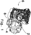
- Figure 1 is a view of a traction motor 2 installed on an engine 6.
- the traction motor 2 is arranged within a housing 4 coupled to the engine 6. Further description of the engine 6 will not be provided. It will be understood that any appropriate type of engine may be used.
- the housing 4 of the motor 2 is coupled to the engine 6 using connectors 8 such as bolts or rivets although the particular type of connector used is not important.
- the engine 6 can produce a power output either by the combustion of an appropriate fuel or by the output of the electric motor 2.
- Such hybrid power supply systems are known and further description will not be provided thereof.
- Such a power supply system is as might be provided in a "hybrid vehicle", i.e. a vehicle powered by a power system capable of providing power either from a combustion engine or from an electric motor.
- a generator is used to generate an electrical output from a rotary input.
- the description herein will be predominantly with respect to use of the device as a motor for generating rotary power, although it could be used instead as a generator of electrical power from a rotary power input.
- the term "rotary device" is used to cover both generators and motors.
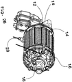
- Figure 2 shows a schematic representation of a motor (a traction motor) as might be provided in the system or engine of Figure 1 .
- the motor 2 has an outer casing 10 that would be in use arranged within the housing 4 shown in Figure 1 .
- the basic structure of the motor and housing is that of a three phase synchronous motor comprising an outer stator including windings together with a coaxially mounted rotor including permanent magnets.
- an AC power signal is provided to the windings such as to generate a rotating magnetic field which causes corresponding rotation of the rotor within the stator.
- this AC power source may be derived from a DC battery or cell assembly with the use of an interconnected inverter.
- FIGS 2A and 2B show views of the stator 22, with all or part of the inner casing 10 removed.
- the rotor can of course not be seen in these figures since it is enclosed by the stator.
- a labyrinthine path 12 is provided within the stator 22.
- the labyrinthine path 12 includes longitudinal path sections 14 together with turning portions 16 arranged generally at the axial ends of the stator.
- An inlet 18 is provided through which a coolant is caused to flow.
- An appropriate pump such as an electric motor driven centrifugal pump may be used to drive coolant through the motor assembly.
- the fluid enters via the inlet 18 and passes up or down along each of the channels 14 along the labyrinthine path 12, changing direction in the turning portions 16, such as to cover substantially all of the external cylindrical surface of the stator 22 with coolant.
- a significant amount of heat transfer from the stator is enabled by the use of such a labyrinthine heat transfer fluid path.
- a branching point 23 is provided at which the coolant flowing through the stator either continues on its path through the stator or splits and continues into the rotor as will now be explained in detail.
- the relative proportion of coolant that flows in each of the rotor and the stator can be controlled by a controllable valve or is determined by the relative dimensions of the various flow paths and conduits.
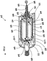
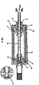
- FIG 3 is a longitudinal cross section through the motor assembly of Figure 2 .
- the motor assembly includes a stator 22 which typically comprises windings (not shown).
- the stator 22 is arranged within the casing 10 of the motor assembly.
- a rotor designated generally at 24 Arranged within the motor assembly 2 is a rotor designated generally at 24.
- the rotor will be described in greater detail below.
- the rotor comprises magnets 26 arranged around a rotor housing 28.
- the magnets are preferably permanent magnets which include materials such as dysprosium.
- the rotor 24 is arranged to rotate due to the interaction of the magnets 28 with the powered windings 22.
- Bearings 30 and 32 are provided to support rotation of the rotor 24 within the motor assembly.
- the magnets are angularly displaced with respect to each other along the length of the rotor housing 24, as will be explained in greater detail below with reference to Figure 7 .
- the rotor housing 24 has a central shaft of rotation 34. At one end thereof, referred to herein as the "second end”, splines 36 are provided to enable rotational coupling between the rotor 24 and an output shaft (not shown). Thus, as the rotor 24 is driven due to the varying AC power signal provided to the stator 22, a rotational output can be taken from the motor assembly 2 via the shaft 34 and splines 36.
- the "first end” a bearing journal 78 is provided for supporting the rotation of the rotor 24.
- the bearing journal 78 couples fixedly to the rotor housing 28.
- the bearing journal 78 is described in greater detail below with particular reference to Figure 8 .
- the labyrinthine path 12 of the stator can be seen.
- a connecting region of the path (not shown) is arranged to provide a route from the labyrinthine path 12 to the inlet to the feed tube of the rotor, as mentioned above with reference to Figure 2A .
- an outlet 38 is provided through which coolant is routed as it leaves the rotor and connects to the output 20 seen in Figure 2B .
- FIGS. 4 and 7 to 13 show the rotor in isolation together with a number of its individual components.
- the rotor 24 comprises an outer wrap 42.
- an air gap 43 is provided between the outer wrap 42 of the rotor 24 and an inner cylindrical surface of the stator 22. Due to the cooling mechanisms provided and described herein heat transfer from the rotor to the stator via this air gap is not required.
- the rotor 24 comprises an inner wall 44, which in part defines, in this example a cylinder of circular cross-section.
- the inner wall 44 may be referred to as a cylindrical housing. This is shown in isolation in Figure 9 . It is preferred that the inner wall housing is cylindrical but other shaped housings can also be used.
- the inner cylindrical housing 44 comprises plural external helical ribs 46 which terminate at the ends of the rotor at rib ends 48.
- the ribs 46 define discrete tortuous channels (in this case helical channels) or fluid paths 50 around the outer cylindrical surface of the inner cylindrical housing 44, defined in part also by the inner cylindrical surface of the rotor housing 28.
- four helical ribs 46 are provided, thereby defining four discrete tortuous paths 50 therebetween.
- the fluid paths 50 could instead be straight and axially aligned. What matters is that the fluid paths cover a significant proportion of the surface of the inner wall to ensure good thermal engagement therewith and with the magnets which they are arranged primarily to cool.
- the stator e.g. application of a voltage to the stator
- the rotor is caused to rotate.
- a cylindrical inner wall can be provided and the fluid paths guide the coolant on the surface of the cylindrical body thus ensuring good coverage of the cylindrical body by the coolant.
- the fluid paths cover at least 35% of the surface of the inner wall.
- the fluid paths are arranged to cover at least 50% and even more preferably at least 75% of the surface are of the inner wall.
- One convenient way by which such surface coverage can be achieved is with the use of helical paths which is therefore preferred.
- the minimum flow rate of fluid within the fluid paths 50 is 0.5m/s. In an alternative the minimum flow rate is set at 1.0m/s or 2m/s.
- the inner wall 44 forms part of the rotor housing which is preferably hollow (whatever its cross-section) as shown in Figure 4 so as to provide a rotor with low mass and inertia. This reduces the power needed to accelerate or decelerate the rotor.
- Any desired number of tortuous channels could be provided. In one example there are four provided, whereas in another only a single tortuous channel is provided.
- the tortuous paths are shown in the example as being helical in shape. However it will be appreciated that other shapes may be used. For example it could be that the paths flow up and down the rotor similar to the flow paths of fluid in the stator as shown in and described with reference to Figure 2B .
- the surface of the inner cylindrical housing is planar with grooves formed in it so as to define the discrete paths for coolant.
- tortuous paths are provided for the flow of coolant on the surface of the rotor housing.
- the grooves could be formed by etching or milling the surface of the inner cylindrical housing 44.
- the cross sectional area of each of the tortuous paths will depend on each specific application although it is preferred that a range of 20 to 60mm 2 will be used.
- ribs or grooves may be formed on the cylindrical inner surface of rotor housing 28, so as to again define tortuous paths 50 on an inner wall of the rotor.
- the tortuous paths in use, with the rotor rotating, the channels or paths 50 rotate together with other components of the rotor, e.g. the magnets.
- the tortuous paths as an integrated part of the component 44, as part of the rotor housing 28, or indeed as a combination of the two.
- additional components could be provided, such as a cylindrical shell to surround and enclose (from the outside) the inner wall 44 or (from the inside) paths formed in the rotor housing 28. What matters is that one or more tortuous paths are provided on or associated with an inner wall of the rotor.
- the rotor also comprises caps or end members 52 and 54 at opposite axial ends of the inner wall or cylindrical housing 44.
- the plugs are fixedly engaged with the inner wall 44 such that the caps and inner wall 44 rotate together.
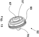
- the plugs 52 and 54 are shown removed from the inner wall or cylindrical housing 44 in Figures 11 and 13 , respectively.
- the rotor 24 has an inlet tube 56 through which coolant enters the rotor.
- the inlet tube 56 is fixedly and rotationally coupled to the plugs 52 and 54. Therefore, as the rotor rotates in use, the inlet tube 56 rotates with it.
- the inlet tube 56 is followed by a fluid coupling member 58 (or coolant tube) which receives the fluid from the inlet tube 56.
- the coupling member 58 is shown in Figure 12 .
- the coupling member 58 serves to connect the rotor caps 52 and 54 and provide a passage for coolant therebetween.
- the coolant tube 58 has grooves 60 and 62 which, in use, are arranged to receive seals for sealing against fluid leakage.
- the inlet tube 56 and coupling member 58 may be provided in combination as a unitary component. In combination either as separate components or a unitary component, they may be thought of as the coolant inlet assembly. Furthermore, the coolant inlet assembly together with the caps 52 and 54 may be provided as a unitary component.
- the coolant tube 58 has a first end arranged to receive the coolant from the inlet tube 56 and a second end 64 arranged to allow the coolant to continue on its passage through the rotor 24 and motor assembly more generally.
- openings 66 ( Figure 12 ) through which coolant exits the tube and passes on to the helical paths 50 on the external cylindrical surface of the component 44.
- a central inlet tube 40 is provided.
- the axis or line of rotation of the rotor lies within the inlet tube 40. This means that when fluid is introduced to the rotor it need not have any rotational velocity already as it is at a substantially central axial position. It is preferable that the inlet to the rotor is axially central (or very close to the central axis) so as to minimise the change in velocity, and hence losses, at the entry.
- the end cap 54 has a socket 110 arranged to receive the second end 64 of the coolant tube 58.
- the cap 54 also has radial bores or cross drillings 68 which define radial transmission paths from the second end 64 of the coolant tube 58 to the start of the helical paths 50.
- the radial bores may be straight or curved but in any event serve to provide one or more conduits from the radially inner region of the device to the radially outer region of the device. In one example, where a double helical path is provided two straight radial bores are provided to define a fluid transmission path from the second end 64 of the coolant tube 58 to the start of the helical paths 50.
- the number of radial bores is preferably selected to correspond to the number of helical paths 50. In some examples however, described in detail below, the number of helical paths is not the same as the number of radial bores or conduits.
- the cap 54 also has an axial protrusion 115, seen clearly in Figure 3 , arranged to be received within the start of the output shaft 72 from the rotor 24.
- the drillings 68 within the cap 54 terminate in substantially circular openings 74 which provide defined and fixed paths for the coolant from the coolant tube 58 to the helical paths 50.
- the housing 44 is cylindrical and has four discrete helical paths defined thereon.
- the housing 44 when arranged in a rotor, is in a fixed angular relationship with the cap 54 such that the openings 74 from the bore or drillings 68 lead into a respective one of the helical paths 50. It is preferred so as to provide for a uniform coating of the coolant on the outer surface of the inner cylindrical housing 44, that at least four discrete helical paths are used. However it will be appreciated that any appropriate number could be used. In one example, three helical paths are used and the angular arrangement of the bores or drillings 68 within the cap 54 provided accordingly.
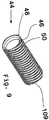
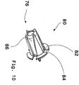
- an impeller 76 (described in detail with reference to Figure 10 ) is provided.
- the impeller is provided coupled to the cap 52 and within a bearing journal 78 for the rotor.
- the impeller 76 is arranged so as to receive the coolant that has passed through the helical paths 50 along the length of the outer cylindrical surface of the inner cylindrical housing 44.
- the impeller 76 serves to route the coolant back towards the central axis of the rotor and motor assembly and from there onwards to an output for regeneration.
- the impeller is a component essential for the invention that prevents relative angular rotation between the fluid and rotor parts when the fluid is encouraged to change its radial displacement. Indeed the conduits and/or guide vanes in the impeller both do this.
- the impeller thus serves as a mechanism that ensures that the fluid that changes radius is always rotated at the same (or close to same) rotational velocity (or angular velocity or whirl velocity) as the rotor throughout its change in radius, until very close to the radius of the inlet or outlet (depending on the direction of fluid flowing through it).
- the impeller is a rotating part of the rotor that has conduits for the flow of fluid whereby rotation of the impeller causes rotation of the fluid within it.
- the fluid does not rotate relative to the impeller, but rotates with the impeller relative to the stator.
- the impeller provides a rotating fluid reaction surface and should be construed broadly in this manner.
- the impeller can serve to impart or remove rotational energy from the fluid as its radius changes.
- the impeller 76 comprises a frusto-conical housing 80 having radial flanges 82.
- the radial flanges 82 define openings 84 through which coolant is arranged to flow from the exits from the helical paths 50 and via conduits 94 within cap 52, described in detail below.
- the impeller is shaped or provided with one or more grooves 86 to provide a controlled passage for the coolant from the conduits 94, onwards to an appropriate exit from the motor assembly.
- the function of the impeller is important in embodiments since it provides a controlled and effective manner to bring the coolant fluid back to a position close to the axis of rotation of the motor assembly prior to exit from the motor itself. This is important since it serves to maintain or ensure zero relative circumferential velocity (whirl) between the coolant and the rotor. This minimises pressure losses in the fluid.
- the impeller 76 functions as a means by which the fluid can increase or decrease its rotational velocity as it moves from a radially outer position, e.g. at the output from radial conduit 94, to a radially inner position at the plenum 38 from which the fluid may be removed from the device.
- the radial distance from the axis of rotation of the inlet tube 58 is less than that of the outlet tube 98, such that the annular region 96 (see Figure 4 ) which defines the outlet from the rotor is radially further from the axis of rotation than the inlet tube.
- the fluid at the start of the drillings 68 (close to the end of the coupling member 58) has little if any tangential velocity. As it passes along the length of the drilling its tangential velocity increases (linearly with radius). However, within the drillings it simply moves along in a straight linear direction. This same effect is achieved at the inlet and outlet of the rotor with the use of the impeller 76.
- the housing 80 of the impeller is preferred to have a generally angled outer surface such as to define a generally frusto-conical form. This enables a smooth deceleration of the coolant as it moves to the centre line velocity whilst avoiding the imparting of whirl to the fluid.
- the grooves or vanes 86 in an aspect may be moulded into the body of the impeller and have a desired or appropriate shape. In one example, the vanes are straight. In another example, the vanes are curved such as to provide a gradual change in direction for coolant flowing therethrough.
- the impeller is a single unitary moulded component with the vanes being an integrated part of it
- the coupling member could include radial deviations such that it is not simply a straight tube along the centre of the rotor.
- the movement of the fluid (and the conduit that carries it) from the input to the rotor to the inlets to the helical paths is axial in that it has a component that is along the axial direction of the rotor.
- the helical paths themselves are axial in this example as they have an axial component for the flow of a coolant between a first end of the rotor and a second distal end of the rotor.
- the fluid flows radially outwardly in the bores or drillings 68.
- the radial passage of the coolant fluid is aided by rotation of the rotor due to centrifugal forces.
- the fluid enters the helical paths and travels back along the helical paths to and for the entire length of the inner cylindrical housing 44, until it reaches openings 93 to radial conduits 94 which guide the fluid into impeller 76 and the vanes 86 therein. From here, the fluid passes along an annular or cylindrical path 96 defined by the outer surface of inlet tube 40 and the inner cylindrical surface of the protrusion 48 of the bearing journal.
- the coolant then passes into plenum 38 such as to be removed from the motor and regenerated.
- the fluid paths 50 have cross sections which are in these examples square or rectangular.
- the inner surfaces of the fluid paths 50 (square or rectangular in cross section in these examples) define what may be referred to as "wetted surfaces".
- the paths 50 are formed so as to achieve a certain wetted surface, as compared, say, to the inner surface 51 of the magnets 26. In general it is desired to maximise the wetted surfaces of the fluid paths so as to achieve an optimal amount of heat transfer to the fluid from the rotor.
- the inner surface 51 of the magnets within the rotor will typically define in cross section a cylinder or prism of some cross-section such as a hexagonal prism, (sometimes staggered along the length of the rotor as in Figure 7 ). As it is typically the inner surface of the magnets through which heat passes from the stator to the fluid paths 50, the wetted surface area of the paths is in some embodiments formed to be of some size or magnitude with respect to the inner surface 51 of the magnets.
- the total wetted surface area of the fluid paths 50 is at least 35% or more preferably at least 50% of the inner surface area of the magnets or indeed the outer surface area of the wall 28.
- the total wetted surface area is at least 75% of the surface area of the magnets. More preferably, the total wetted surface area is at least 100% of the surface area of the magnets and most preferably, the total wetted surface area is greater than 100%, e.g. at least 125% or 150%, of the inner surface area 51 of the magnets.
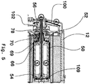
- Figure 5 shows a further example of the overall passage for fluid through the motor.
- the coolant enters the rotor from the serpentine path 12 of the stator 22.
- the fluid passes into the inlet tube 56 along fluid feed conduit or path 100.
- the fluid passes through the length of the coolant feed tube assembly, out through the bores or drillings 68 within the cap 54, along the helical paths 50, radially inwardly along guided conduits 52, through the impeller 76 and then through a plenum 104 and out along an output conduit 102.
- the materials from which the rotor parts are preferably manufactured include appropriate metals such as steels and Aluminium.
- the magnet seats 28 and bearing journal 78 are typically made of steel, whereas the plugs 52 and 54 and rotor cylinder 44 are typically made of Aluminium.
- the impeller is preferably made of a plastic material. The skilled person would be aware of the materials from which other parts of the rotor and motor assembly could be formed.
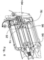
- FIG. 6 shows in slightly greater detail the output path for the coolant fluid from the rotor and motor assembly.
- a plenum 104 is provided which serves as a chamber to receive the fluid from the impeller 76 as described above.
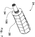
- the rotor 24 comprises seats 28 upon which are provided permanent magnets 26 (not shown in Figure 7 ).
- the rotor with the seats 28, at any point along the length of rotor, has a hexagonal cross-section.
- the outer surfaces of the magnets are preferably curved such that once arranged on the seats 28, the outer surface of the rotor is cylindrical, as seen in Figure 4 .
- each set of magnets that forms a ring on the rotor is angularly offset slightly as compared its upstream and/or downstream neighbours. As mentioned above, this reduces the magnetic-field-induced harmonic distortion in the driving A/C waveform.
- the output member 34 of the rotor can be seen clearly together with grooves 106.
- the grooves 106 serve to house one or more seals for the rotor within the motor assembly.
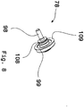
- FIG 8 shows the bearing journal for the rotor.
- the bearing journal 78 includes grooves 108 which, again, are preferably used for one or more seals.
- the bearing journal is arranged within bearings 30 which serve to control the positioning of the rotor within the motor assembly. Referring to both Figures 3 and 8 , the bearing journal will now be described in greater detail.
- the bearing journal comprises on one axial side, the projection 98 described above which helps to define the outlet path for the coolant from the rotor.
- the bearing journal also includes an annular flange 99 having notches 109.
- the flange and notches provide means by which the bearing journal 78 may be fixedly coupled to the wall 28 of the rotor.
- Figure 3 shows how the wall 28 may be provided with recesses 55 for receiving fixing elements (not shown) such a screws or rivets.
- fixing elements such as screws or rivets.
- appropriately sized holes could be provided in the flange to receive the fixing elements.
- FIGs 11 and 13 show the rotor caps 52 and 54, respectively.
- the rotor cap 54 is shown which would in use be arranged at the second distal end of the rotor, i.e. the end through which fluid leaves the inlet tube 58.
- the rotor cap 54 includes cross drillings 68 which define the radial conduits through which the fluid passes as it moves from the inlet tube 58 to the helical paths 50.
- Flats 112 are provided which are preferably used to ensure that the cross drillings 68 align with the openings 66 in the distal end of the inlet tube 58.
- a circular rim 111 is provided which is sized to engage with the inner cylindrical surface of the cylindrical housing component 44.
- annular ring flat 113 is provided which engages the annular end surface 109 (see Figures 6 and 9 ) of the cylindrical housing component 44.
- An axial tubular boss 110 is provided which is sized and arranged to receive within it the end of the inlet tube 58, such that coolant that passes along the inlet tube 58 is routed through the openings 66 and onwards into the cross drillings 68.
- Toroidal grooves 115 and 117 are provided which serve to reduce the weight and inertia of the rotor cap 54 without affecting its function in other ways.
- the rotor cap 52 arranged in use at the first end of the rotor will now be described in detail.
- the cap 52 comprises an axial projection 70 on which is mounted the impeller 76.
- a cylindrical boss 57 In addition on the opposite axial surface of the cap 52 there is provided a cylindrical boss 57.
- the boss 57 has a cylindrical recess 67 sized to receive the first end of the inlet tube 58.
- the cylindrical recess 67 has an inner shoulder 69 which engages the end axial toroidal surface of the inlet tube 58.
- the projection 70 is hollow and in combination with the inlet tube 58 engaged with the shoulder 69, provides a substantially continuous conduit for coolant as it passes into the motor.
- Radial grooves 94 provide a route for the coolant received from the helical paths 50 through the cap 52 and onwards into the impeller 76.
- circular opening 93 are provided as the inlets to the radial grooves 94.
- the number of grooves is selected to correspond to the number of helical paths 50 provided on the cylindrical housing component 44. Accordingly in almost all cases the number of radial grooves in the two caps 52 and 54 will be the same so as to correspond to the number of helical paths on the cylindrical housing component 44.
- the radial grooves are preferably straight grooves of circular cross section arranged in a radial direction. However, in some examples, the grooves could be curved.
- FIG. 6 shows curved grooves 94 in the caps 52 and 54.
- Either or both of the caps 52 and 54 could be provided with straight and/or curved radial grooves, but in all cases the grooves route fluid between a circumferential area of maximum radius and an inner central region of smaller radius.
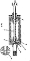
- Figures 14 and 15 show further examples of rotors for use in a motor assembly.
- Figure 14 shows a further example of a rotor for use in a motor assembly.
- a cylindrical housing component 44 is provided with end caps 52 and 54.
- An impeller 76 is provided between the end cap 52 and the rotor journal bearing 78.
- the end cap 54 includes a longitudinal drilling 114 as well as the axial cross drillings 68, described above.
- the operation and function of the rotor will be as described above, with reference to, e.g., Figures 3 and 4 .
- Figures 14 and 15 show clearly the fluid inlets and outlets from the rotor. As can be seen, the fluid outlet is at a larger radius than the fluid thus enabling the rotor to self-pump as a result of the centrifugal forces imparted to the fluid by rotation of the rotor.
- Figure 15 shows a further embodiment.
- the inlet tube 58 continues into a recess 116 within the cap 54. Openings 118 are provided in the tube 58 to align with the inputs 120 to the cross drillings 68.
- the openings are simple drillings within the inlet tube to allow the coolant fluid to exit radially or from the side of the inlet instead of from the end face.
- the operation and arrangement of the rotor is as described above with reference to other of the figures.
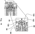
- Figure 16 shows a schematic representation of one example of an inlet tube seal that is preferably used at the fluid input to the motor assembly.
- the inlet tube 56 is coupled to the plenum housing 122 via an energised face seal 124.
- a sealing member 126 is provided around the input to the tube 56.
- the sealing member is preferably formed of a low friction material such as PTFE and is provided in the form of a "top hat”.
- the bore of the PTFE seal 124 is transition fit onto the inlet tube 56.
- the PTFE seal 124 has a tight fit to the inlet tube and a loose fit to the housing and is designed to seal effectively against the perpendicular face of the stationary housing 122. This permits good sealing despite any "wobble" or run-out in the shaft.
- the use of the arrangement described herein enables peak component temperatures within the stator to be limited to approximately 200 degrees Centigrade.
- the component temperatures of the stator are limited to 207 degrees Centigrade.
- the rotor cooling using the disclosed examples, is able to limit the peak component temperatures of the rotor wrap to within the range 160 to 210 degrees Centigrade.
- the overall motor system pressure drop is limited to 0.5 or 0.4 bar, given an overall flow rate of 15 litres per minute, sufficient to cool a motor of output greater than 100kW and total package volume of 8 litres.
- the system is able to hold coolant without leaks at greater than 3.5 bar gauge inlet pressure.
- the overall pressure of fluid within the outboard extremities of the rotor is dominated by the centrifugal pressure (proportional to the square of rotational speed).
- this centrifugal pressure contributes an additional 17 bar when the frequency of rotation is 18,000 rpm and the rotor flow paths are at a radius of 30mm. It is envisaged that in future using the rotor and cooling described herein speeds of up to 25,000rpm could be achieved.
- the high fluid velocity is attainable which therefore enables good heat transfer to the coolant.
- a higher flow rate or fluid velocity ensures that the resident time of fluid within the motor is correspondingly small.
- the fluid is continually replenished with fresh cool fluid and therefore able to receiver a higher amount of heat in unit time as well as increasing the heat transfer coefficient.
- high amounts of cooling can be achieved.
- more than 50% of the rotor heat has been removed using the cooling mechanism and methods described herein.
- thermochromic paint it has been determined that the rotor temperature in a motor of 8 litres overall package volume was less than 50 degrees centigrade above the coolant temperature after 10 minutes of motor operation at a power of 110 kW.
- the use of the impeller also enables minimal pressure losses which therefore avoids the need for a high pressure coolant pump and complex sealing systems.
- the coolant is close to the source of the heat and therefore provides for good heat transfer therefrom.
- the use of plural helical paths ensures uniform coverage of hot parts of the rotor, again, ensuring good heat transfer capability.
- the disclosed embodiment would typically be used with an ethylene-glycol and water mixture, although other coolants may also be used. All or part of the coolant passes through the rotor cooling system. The coolant enters and leaves the rotor close to the rotor axis, as described above. As mentioned above, the outlet, although close to the rotor axis is at a larger radius than the inlet thus enabling the self-pumping nature of the rotor to be realised. It is preferred that, as in the enclosed embodiments, the coolant enters and leaves the rotor at the same longitudinal or axial end of the rotor. This enables a simple connection to the vehicle transmission at the other end of the rotor. In other words, since no conduits for coolant fluid need to be provided at the distal end of the rotor, the output can lead directly to an output shaft without the need to provide any fluid conduits and or corresponding seals.
- a rotating sealing system is provided which prevents fluid entering the rotor cavity in the stator. This prevents fluid sheer friction losses and heat generation.
- a further rotating sealing system may be provided to separate inlet and outlet fluids mixing. This maximises the effectiveness of the system. It is to be noted that the cooling heat transfer occurs in the zone at significantly larger radius than the inlet and outlets. In other words, since the cooling takes place on the outer cylindrical surface of the inner cylindrical housing 44, this is at a significant radial distance from the axis of the rotor. This ensures good heat transfer (since the heat transfer is at the source of the heat) but also minimum rotor mass and inertia due to the hollow nature of the inner cylindrical housing 44.
- the impeller is used to maintain or guarantee zero relative circumferential velocity (whirl) between the coolant and the rotor. This minimises pressure losses in the fluid and thus obviates the need for a high pressure pump to force the coolant through the motor.
- a multi-start helical path for the coolant in the heat transfer zone is provided. This ensures high fluid velocity and even and substantially uniform fluid distribution.
- the component parts of the rotor housing can be made to normal manufacturing tolerances.
- a sealed air filled cavity is provided under the heat transfer zone which minimises rotor inertia.
- the cooling liquid is provided so as to flow in the opposite direction as previously described.
- the cooling fluid passes along the annular or cylindrical path 96 defined by the outer surface of inlet tube 40 and the inner cylindrical surface of the protrusion 48 of the bearing journal. From here the fluid flows through the impeller 76 guided by the vanes 86. It then flows on to the radial conduits 94 which guide the fluid to the start of the helical path or paths around the rotor.
- the fluid passes along the entire length of the inner cylindrical housing 44 and eventually reaches the one or more radial drillings or bores 68 along which it flows radially inwardly to reach the conduit 58, referred to above as the "inlet tube".
- the fluid may be considered an "outlet tube".
- the fluid passes along the length of the tube 58 from the distal end towards the proximal end where it can be fed out of the device.
- the fluid path is substantially opposite to that described above where the fluid enters the assembly via the inlet tube 58.
- a pump is provided to provide additional or sufficient fluid pressure to drive the fluid in the manner described.
- the radial bores may be straight or curved but in this case serve to provide one or more conduits from the radially outer region of the device to the radially inner region of the device.
- two straight radial bores are provided to define a transmission path to the second end 64 of the coolant tube 58 from the end of the helical paths 50.
- the number of radial bores is preferably selected to correspond to the number of helical paths 50.
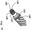
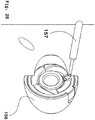
- Figure 17 is a schematic representation of an aspect of a rotor 138 for use in a motor.
- the rotor is generally similar to that described above with reference to, for example, Figures 3 to 6 .
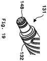
- the rotor has three general sections, which are the first end section 131, the central section 133 and the second end section 135.
- the first and section end sections 131 and 135 generally include journal parts for engagement with rotor bearings within a motor or other rotary device.
- the first and second end sections 131 and 135 include a number of journal surfaces for engagement with bearings within a rotary device such as a motor or generator.
- first end section 131 comprises generally cylindrical bearing journal 123 for engagement with a bearing (not shown).
- a number of annular grooves 127 are provided within which seals such as O-rings and the like will be provided to avoid or reduce fluid leakage.
- the tortuous paths are defined by double helixes 130.
- the helixes are "double" in that a single feed inlet 132 feeds two parallel connected paths or branches134 and 136. Liquid enters the double helix via the inlet 132 and passes along both branches 134 and 136 of the helix.
- Return inlets 150 are provided at the second end of the central section 133 of the rotor, to receive fluid from the helical paths and direct it back through the rotor towards fluid outlets 148 in the first end section 131 described in detail below.
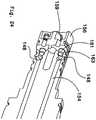
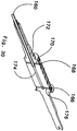
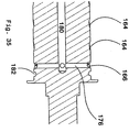
- Figures 23 and 24 show in more detail a part longitudinal section through the first end section 131 of the rotor.
- a number of feed conduits 140 are provided through which a cooling liquid is fed into the rotor.
- the feed conduits 140 comprise parallel axial sections 142 and subsequently radial sections 144 along which the fluid flows so as to reach the inlets 132 to the helical paths 130.
- Figure 23 shows clearly a single inlet 132 feeding two branches 134 and 136 of helical path 130.
- Inlets 146 to the axial sections 142 of feed conduits 140 are provided at an axial end of the rotor. In use, once liquid is fed into the rotor it will pass along the feed conduits and then along the helical paths towards the second end section 135 of the rotor. Once there, it passes through return ports and conduits as will now be described with reference, in particular, to Figures 17 , 18 , 20 , 24 and 26 .
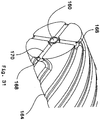
- return ports 148 are provided which serve as an outlet for cooling liquid that has passed through the rotor. Cooling liquid that has passed along the helical paths 134 and 136 reaches the end of the central section 133 close to the second end 135 of the rotor and then commences its passage back towards the first end section 131.
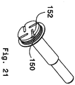
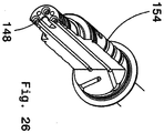
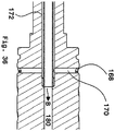
- Passage of the fluid through the rotor is thus as follows. Fluid is introduced via the feed conduits140. The fluid then passes along the radial sections 144 ( Figures 22 and 23 ) of the feed conduits140and on to the helical path inlets 132. From here, the fluid passes along the double helical paths 130 until it reaches the distal end of the rotor, i.e. the part of the central section 133 closest to the second end section 135. At this point, the fluid passes into return inlets 150. Radial inlet tubes or drillings 152 ( Figure 21 ) are provided to route fluid from the return inlets 150 into one or more axial return paths 154 (see Figure 26 ).
- the radial inlet tubes or drillings are formed within the body of the rotor and again, as with the feed conduits 140, any appropriate number can be provided. Typically the number will be the same as the number of helical paths. However, where double helixes are provided as in the aspect shown in Figure 17 , half the number of radial inlet tubes 152 will be provided.
- the inlet tubes 152 are arranged so as to lead to the inlets of the axial return paths 154.
- the inlet tubes, in the aspect shown are straight but as with the radial conduits 68 described above, they may be curved. It is simply required that they provide a generally radial path for the liquid to move from the helical paths to the axial return paths 154. Thus, in one aspect they have a generally spiral configuration leading from the inlets 150 to the axial return paths 154.
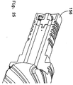
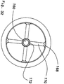
- an impeller 156 is provided.
- the impeller 156 is coupled to the rotor and rotates with it. It serves to provide rotational velocity to the cooling liquid prior to its introduction to the feed conduits 140.
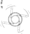
- the inlets to the impeller 158 are not on the central axis of rotation of the rotor and, as the impeller will be rotating with the rest of the rotor at high rotational speeds, its inputs will be moving at some significant tangential velocity. So as ensure that fluid that enters is in the same or similar rotational frame of reference, some means such as fluid jets may be provided to impart tangential velocity to the fluid before it enters the impeller. This is described in more detail below with reference to Figures 27 and 28 .
- the impeller 156 has curved inlet paths 158 shown most clearly in Figure 20 .
- Jets or inlets 157 for jets may be provided to supply the liquid to the impeller 156.
- the jets 157 serve to provide the liquid with some tangential (as well as axial) velocity.
- the blade angle of the impeller curved surfaces 158 is shallow, thus reducing or minimising losses in fluid pressure whilst still imparting desired rotational or velocity to the liquid as it passes into the rotor.
- FIG 24 is a schematic representation of an impeller 156 and coupling spigots for a rotor such as that shown in Figure 17 , all arranged generally at the first end section 131 of the rotor.
- the impeller 156 comprises impeller inlet paths 159 through which liquid passes as it enters the rotor.
- a plurality of spigots 161 are provided which engage with corresponding openings 163 in the rotor body, seen clearly in Figures 18 and 23 .
- 4 spigots 161 are provided.
- the spigots 161 also form end faces to close off the axial return paths 154. Thus once fluid has reached the end of axial return paths 154 it is forced out of the return ports or outlet openings 148 via engagement with the end faces of the spigots 161.
- Figures 17 to 28 operates in a manner substantially similar to that of the embodiment described above with reference to Figures 1 to 16 and so further description will not be provided.
- various seals and bearings are provided to enable the rotor to operate within a rotary device such as a motor or generator.
- Figures 29 to 37 show a further aspect of the rotor.
- Figures 29 to 37 is similar to the embodiment of Figures 1 to 17 .
- the inlet and outlet paths, by which fluid is introduced to and removed from the rotor, are substantially parallel and co-axial with the rotor.
- a central inlet conduit 160 is provided.
- the outlet for the fluid that has passed through the rotor 162 is along the annular pathway surrounding the inlet conduit 160.
- the rotor has three general sections, which are the first end section 131, the central section 133 and the second end section 135.
- the first and section end sections 131 and 135 generally include journal parts for engagement with rotor bearings within a motor or other rotary device and/or appropriate seals and the like.
- the rotor of Figures 29 to 31 is similar to that of Figure 17 in that double helixes 164 are provided.
- the inlet 166 to the helix is at the distal end of the rotor, i.e. at the end closest to the second end section 135.
- the fluid thus passes along the central conduit 160 until it passes radially outwards to the inlets 166.
- the fluid is forced along the helical paths 164 until it reaches the outlets 168 from the helical paths.
- the fluid flows along radial conduits 170 and into the annular outlet path 172.
- Figure 30 shows a section through the shaft assembly in which the central conduit 174 can be seen along which fluid is communicated to radial conduits 176 and subsequently to inlets 166.
- Figure 31 the helical paths 164 can be seen clearly terminating at outlets 168 from the helical paths leading into the radial conduits 170.
- Figure 32 is an end-on transverse section through the rotor showing the outlets 168 from the helical paths (also the inlets to the radial conduits 170).
- Figure 33 is a schematic representation of a section through the liquid inlet-outlet manifold and Figure 34 is a schematic representation of a section through a rotor including the liquid inlet-outlet manifold of Figure 33 .
- the inlet conduit 160 is able to receive coolant liquid from its open end 178. The liquid flows along inlet conduit 160 in the direction B and into the central conduit 180. Once the liquid has passed along the helical paths along the outer surface of the rotor, it returns along the radial inlet conduits 170 seen most clearly in Figure 36 . At this point, the liquid enters the annular outlet conduit and from here is removed from the assembly.
- the outlet is radially further from the axis of rotation than the fluid inlet to the rotor so that the device is self-pumping and again acts analogously to a gravitational syphon.
- the inlet conduit 160 functions as the impeller since liquid fed into it will be imparted with rotational velocity as well as axial velocity.
- the impeller thus serves as a mechanism that ensures fluid that enters it is rotated at the same (or close to same) rotational velocity (or angular velocity or whirl velocity) as the rotor.
- the inlet conduit or impeller 160 is a rotating part of the rotor that has a central axial conduit for the flow of fluid whereby rotation of the impeller causes rotation of the fluid within it.
- Figure 35 shows a section through the coolant inlet port 166 to the helical paths on the rotor. Coolant received via the central conduit 180 passes along the radial conduits 176, to one of the corresponding inlets 166 and then into the helical paths 164.
- Various seals and the like may be provided as required to ensure efficient operation of the device.
- a seal groove 182 is provided which may receive an O-ring.
- the O-ring like all other O-rings provided for operation with the rotor may be formed of an appropriate material, e.g. a rubber or elastomeric material.
- Figures 36 and 37 show schematic cross sections through a part of the shaft assembly showing the liquid or coolant inlet and outlet parts.
- coolant is provided via inlet region 184. From there, the coolant flows in through the inlet conduit 160 and onwards through the rotor as described above. On its return, once the fluid has passed along the helical or tortuous paths described above, it passes through ports 168 and along the radial conduits 170 and from there into annular outlet 172. Then the coolant flows into radial outlet conduits 186 and subsequently to outlet 188.
- various seals 190 are provided to determine fluid flow and stop unwanted leakage.
Landscapes
- Engineering & Computer Science (AREA)
- Power Engineering (AREA)
- Motor Or Generator Cooling System (AREA)
- Connection Of Motors, Electrical Generators, Mechanical Devices, And The Like (AREA)
- Iron Core Of Rotating Electric Machines (AREA)
Applications Claiming Priority (2)
| Application Number | Priority Date | Filing Date | Title |
|---|---|---|---|
| GB1218092.3A GB2501952B (en) | 2012-10-09 | 2012-10-09 | A motor and a method of cooling a motor |
| PCT/GB2013/052558 WO2014057245A2 (en) | 2012-10-09 | 2013-10-01 | A rotary device, a motor and a method of cooling a motor |
Publications (2)
| Publication Number | Publication Date |
|---|---|
| EP2907222A2 EP2907222A2 (en) | 2015-08-19 |
| EP2907222B1 true EP2907222B1 (en) | 2022-01-05 |
Family
ID=47294518
Family Applications (1)
| Application Number | Title | Priority Date | Filing Date |
|---|---|---|---|
| EP13771207.1A Active EP2907222B1 (en) | 2012-10-09 | 2013-10-01 | A rotary device, a motor and a method of cooling a motor |
Country Status (6)
| Country | Link |
|---|---|
| US (1) | US20150288255A1 (enExample) |
| EP (1) | EP2907222B1 (enExample) |
| JP (1) | JP6542667B2 (enExample) |
| CN (1) | CN104838567B (enExample) |
| GB (1) | GB2501952B (enExample) |
| WO (1) | WO2014057245A2 (enExample) |
Families Citing this family (54)
| Publication number | Priority date | Publication date | Assignee | Title |
|---|---|---|---|---|
| DE102014207470A1 (de) * | 2014-04-17 | 2015-10-22 | Zf Friedrichshafen Ag | E-Maschine mit einem gekühlten Rotor |
| DE102014107843B3 (de) | 2014-06-04 | 2015-11-26 | Thyssenkrupp Presta Teccenter Ag | Medientransport in Rotorwelle |
| US10554091B2 (en) * | 2014-08-22 | 2020-02-04 | Regal Beloit America, Inc. | Electric machine with rotor, stator and housing cooling passages |
| US20160294231A1 (en) | 2015-04-02 | 2016-10-06 | Hamilton Sundstrand Corporation | Stator heat transfer feature |
| FR3036553B1 (fr) * | 2015-05-20 | 2018-05-18 | Valeo Equipements Electriques Moteur | Machine electrique tournante a circuit de refroidissement optimise |
| US10277096B2 (en) * | 2015-11-13 | 2019-04-30 | General Electric Company | System for thermal management in electrical machines |
| DE102016200423A1 (de) * | 2016-01-15 | 2017-07-20 | Continental Automotive Gmbh | Elektrische Maschine |
| CN105680729A (zh) * | 2016-03-31 | 2016-06-15 | 亿昇(天津)科技有限公司 | 一种磁悬浮电机 |
| DE102016209173A1 (de) * | 2016-05-25 | 2017-11-30 | Volkswagen Aktiengesellschaft | Rotor für eine elektrische Maschine |
| GB2552678B (en) * | 2016-08-02 | 2019-04-03 | Integral Powertrain Ltd | A rotary device, a motor and a method of cooling a motor |
| DE102016216685A1 (de) * | 2016-09-02 | 2018-03-08 | Continental Automotive Gmbh | Rotor für eine elektrische Maschine |
| DE102016118026B4 (de) | 2016-09-23 | 2022-01-27 | Hirschvogel Umformtechnik Gmbh | Rotor, insbesondere Rotor für eine elektrische Maschine, elektrische Maschine und Verfahren zur Herstellung eines Rotors |
| GB2562760B (en) | 2017-05-24 | 2020-04-01 | Equipmake Ltd | A rotor for an electric motor |
| WO2019032686A1 (en) | 2017-08-08 | 2019-02-14 | American Axle & Manufacturing, Inc. | ELECTRIC DRIVE MODULE EQUIPPED WITH A THERMAL DISSIPATOR INSERT ENGINE IN A ROTOR SHAFT |
| JP6888514B2 (ja) * | 2017-10-18 | 2021-06-16 | トヨタ自動車株式会社 | 回転電機のロータ |
| US10752373B2 (en) * | 2017-11-16 | 2020-08-25 | Textron Innovation Inc. | Air management systems for stacked motor assemblies |
| CN110277842A (zh) * | 2018-03-15 | 2019-09-24 | 蔚来汽车有限公司 | 带有冷却套件的电机 |
| DE102018118276A1 (de) | 2018-07-27 | 2020-01-30 | Valeo Siemens Eautomotive Germany Gmbh | Rotoranordnung für eine elektrische Maschine, elektrische Maschine für ein Fahrzeug und Fahrzeug |
| DE102018118275A1 (de) * | 2018-07-27 | 2020-01-30 | Valeo Siemens Eautomotive Germany Gmbh | Rotoranordnung für eine elektrische Maschine, elektrische Maschine für ein Fahrzeug und Fahrzeug |
| US11121597B2 (en) * | 2018-08-08 | 2021-09-14 | Schaeffler Technologies AG & Co. KG | Hybrid module including rotor having coolant flow channels |
| US11146133B2 (en) * | 2018-08-30 | 2021-10-12 | General Electric Company | Electric machine with rotor coolant and lubrication distribution system, and systems and methods of cooling and lubricating an electric machine |
| US11387693B2 (en) * | 2018-12-12 | 2022-07-12 | Aurora Flight Sciences Corporation | Motor cooling system and method |
| EP3667870B1 (en) * | 2018-12-13 | 2023-07-26 | Hamilton Sundstrand Corporation | Cooling of electric motors |
| KR102172262B1 (ko) * | 2019-01-25 | 2020-10-30 | 엘지전자 주식회사 | 전동기 |
| US11329585B2 (en) * | 2019-01-25 | 2022-05-10 | General Electric Company | Electric machines with air gap control systems, and systems and methods of controlling an air gap in an electric machine |
| DE102019211559A1 (de) * | 2019-08-01 | 2021-02-04 | Zf Friedrichshafen Ag | Elektrische Maschine eines Fahrzeuges mit einer Kühlfluidversorgung |
| BE1027496B1 (nl) * | 2019-08-12 | 2021-03-16 | Atlas Copco Airpower Nv | Compressorinrichting |
| US10933375B1 (en) | 2019-08-30 | 2021-03-02 | Fluid Equipment Development Company, Llc | Fluid to fluid pressurizer and method of operating the same |
| GB2586991B (en) | 2019-09-11 | 2021-12-29 | Rolls Royce Plc | Electric drive systems |
| GB2587187B (en) | 2019-09-11 | 2022-07-27 | Rolls Royce Plc | Electric Machines |
| GB2587186A (en) * | 2019-09-11 | 2021-03-24 | Rolls Royce Plc | Electric Machines |
| GB2586989B (en) | 2019-09-11 | 2022-07-27 | Rolls Royce Plc | Electric Machines |
| DE102019214695A1 (de) * | 2019-09-25 | 2021-03-25 | Mahle International Gmbh | Elektrische Antriebsvorrichtung und Herstellverfahren für eine Wärmetauschereinrichtung, insbesondere zur Verwendung bei einer elektrischen Antriebsvorrichtung |
| US11476733B2 (en) * | 2019-11-01 | 2022-10-18 | GM Global Technology Operations LLC | Electric machine with forced convection-based rotor cooling of rotor magnets |
| WO2021117884A1 (ja) * | 2019-12-12 | 2021-06-17 | 株式会社Ihi | 回転装置 |
| CN110855065B (zh) * | 2019-12-13 | 2020-06-12 | 浙江巨龙电机股份有限公司 | 一种高效散热电机 |
| CN119315766A (zh) | 2020-01-15 | 2025-01-14 | 华为数字能源技术有限公司 | 电机转子及汽车 |
| CN111162633A (zh) * | 2020-01-15 | 2020-05-15 | 华为技术有限公司 | 电机转子及汽车 |
| DE102020110861B4 (de) | 2020-04-21 | 2022-03-24 | Iav Gmbh Ingenieurgesellschaft Auto Und Verkehr | Vorrichtung zur Kühlung einer elektrischen Maschine |
| FR3111025B1 (fr) * | 2020-05-29 | 2023-06-23 | Novares France | Rotor pour moteur électrique muni d’un circuit de refroidissement |
| EP3965266B1 (en) * | 2020-09-03 | 2023-11-08 | Wuhan Lotus Cars Co., Ltd. | Electric machine rotor cooling cartridge |
| CN112104119A (zh) * | 2020-09-15 | 2020-12-18 | 华育昌(肇庆)智能科技研究有限公司 | 一种永磁同步电机高强度贴合的电机转子 |
| US12166381B2 (en) * | 2020-12-30 | 2024-12-10 | Volvo Car Corporation | Stator cooling for electric machines |
| US11824425B2 (en) | 2021-02-04 | 2023-11-21 | Volvo Car Corporation | Electric machine |
| KR102618055B1 (ko) * | 2021-05-20 | 2023-12-27 | 현대모비스 주식회사 | 로터 조립체 및 이를 포함하는 모터 |
| SE545702C2 (en) * | 2022-03-11 | 2023-12-12 | Scania Cv Ab | A rotor for an electric rotating machine |
| CN114598078B (zh) * | 2022-03-21 | 2025-11-18 | 珠海格力电器股份有限公司 | 电机转子组件、电机、车辆 |
| DE102022203783A1 (de) | 2022-04-14 | 2023-10-19 | Volkswagen Aktiengesellschaft | Elektrische Maschine mit einer Kühlleitung |
| US12224627B2 (en) * | 2022-07-19 | 2025-02-11 | Borgwarner Inc. | Rotor assembly for an electric motor |
| US12323025B2 (en) * | 2022-10-24 | 2025-06-03 | Schaeffler Technologies AG & Co. KG | Heat exchanger system for an electric motor with fluid circuits arranged between shafts |
| US12273011B2 (en) * | 2023-02-06 | 2025-04-08 | Schaeffler Technologies AG & Co. KG | Electric motor shaft including inner helix pattern |
| US20250079917A1 (en) * | 2023-09-01 | 2025-03-06 | Borgwarner Inc. | Rotor having a plurality of cooling jets and electric motor including the same |
| US20250112524A1 (en) * | 2023-09-28 | 2025-04-03 | Deere & Company | Closed-circuit rotor cooling arrangement and electric machine having same |
| US20250192642A1 (en) * | 2023-12-12 | 2025-06-12 | Ge Aviation Systems Llc | Electric machine and method of operating aircraft |
Family Cites Families (24)
| Publication number | Priority date | Publication date | Assignee | Title |
|---|---|---|---|---|
| GB191416979A (en) * | 1914-07-17 | 1915-07-08 | Siemens Brothers Dynamo Works | Improvements in or relating Cooling Arrangements for Dynamo-electric Machinery. |
| DE3622231A1 (de) * | 1986-07-02 | 1988-01-07 | Bosch Gmbh Robert | Permanentmagnetrotor fuer elektrische maschinen |
| US5288215A (en) * | 1992-11-19 | 1994-02-22 | Chancellor Dennis H | Integral motor centrifugal pump |
| DE4320559A1 (de) * | 1993-06-21 | 1994-12-22 | Siemens Ag | Elektrische Maschine mit einem innengekühlten Läufer |
| JPH10285876A (ja) * | 1997-03-28 | 1998-10-23 | Toyo Electric Mfg Co Ltd | 羽根車付き液冷式回転電動機 |
| EP0989658A1 (fr) * | 1998-09-28 | 2000-03-29 | The Swatch Group Management Services AG | Machine électrique asynchrone refroidie par liquide |
| GB9920581D0 (en) * | 1999-09-01 | 1999-11-03 | Alstom Uk Ltd | Improvements in rotating electrical machines |
| JP2001190047A (ja) * | 1999-12-28 | 2001-07-10 | Honda Motor Co Ltd | 電動モータのロータ冷却装置 |
| US6879069B1 (en) * | 2000-06-21 | 2005-04-12 | Bae Systems Controls Inc. | Rotating machine with cooled hollow rotor bars |
| JP2002325394A (ja) * | 2001-04-26 | 2002-11-08 | Nissan Motor Co Ltd | 電機子 |
| JP2003079101A (ja) * | 2001-06-21 | 2003-03-14 | Nissan Motor Co Ltd | 回転電機の冷却構造 |
| US6727609B2 (en) * | 2001-08-08 | 2004-04-27 | Hamilton Sundstrand Corporation | Cooling of a rotor for a rotary electric machine |
| JP3758583B2 (ja) * | 2002-02-06 | 2006-03-22 | 日産自動車株式会社 | 回転体の冷却構造 |
| JP2004180491A (ja) * | 2002-11-11 | 2004-06-24 | Mitsubishi Electric Corp | 永久磁石式回転電機 |
| US7021905B2 (en) * | 2003-06-25 | 2006-04-04 | Advanced Energy Conversion, Llc | Fluid pump/generator with integrated motor and related stator and rotor and method of pumping fluid |
| US7282823B2 (en) * | 2004-10-29 | 2007-10-16 | Emerson Electric Co. | Self-cooling electric machine |
| JP5017120B2 (ja) * | 2005-11-09 | 2012-09-05 | 株式会社東芝 | 回転電機用回転子及び回転電機 |
| JP5123008B2 (ja) * | 2008-03-05 | 2013-01-16 | 株式会社ミツバ | ブラシレスモータ |
| US8022582B2 (en) * | 2008-12-30 | 2011-09-20 | Caterpillar Inc. | Liquid cooled permanent magnet rotor |
| DE102009025929A1 (de) * | 2009-06-05 | 2010-12-09 | Ulrich Spevacek | Läuferaufbau für eine permanentmagneterregte, rotierende elektrische Maschine |
| CN102906969B (zh) * | 2010-04-23 | 2015-05-13 | 株式会社Ihi | 旋转机械 |
| GB201014073D0 (en) * | 2010-08-24 | 2010-10-06 | Dyson Technology Ltd | Rotor core assembly |
| DE102010064010A1 (de) * | 2010-12-23 | 2012-06-28 | Siemens Aktiengesellschaft | Elektrische Maschine mit geschlossenem, autarkem Kühlmediumkreislauf |
| US8405262B1 (en) * | 2011-11-30 | 2013-03-26 | Kollmorgen Corporation | Cooling of electric motor with coolant pipe and conduction plates or cups |
-
2012
- 2012-10-09 GB GB1218092.3A patent/GB2501952B/en active Active
-
2013
- 2013-10-01 US US14/434,703 patent/US20150288255A1/en not_active Abandoned
- 2013-10-01 WO PCT/GB2013/052558 patent/WO2014057245A2/en not_active Ceased
- 2013-10-01 JP JP2015536217A patent/JP6542667B2/ja active Active
- 2013-10-01 EP EP13771207.1A patent/EP2907222B1/en active Active
- 2013-10-01 CN CN201380063993.0A patent/CN104838567B/zh active Active
Also Published As
| Publication number | Publication date |
|---|---|
| CN104838567B (zh) | 2019-07-30 |
| WO2014057245A3 (en) | 2015-05-14 |
| CN104838567A (zh) | 2015-08-12 |
| GB2501952B (en) | 2014-03-26 |
| GB201218092D0 (en) | 2012-11-21 |
| GB2501952A (en) | 2013-11-13 |
| US20150288255A1 (en) | 2015-10-08 |
| WO2014057245A2 (en) | 2014-04-17 |
| JP2015534803A (ja) | 2015-12-03 |
| EP2907222A2 (en) | 2015-08-19 |
| JP6542667B2 (ja) | 2019-07-10 |
Similar Documents
| Publication | Publication Date | Title |
|---|---|---|
| EP2907222B1 (en) | A rotary device, a motor and a method of cooling a motor | |
| US8154158B2 (en) | Cooling an electrical machine | |
| CN109698574B (zh) | 电机 | |
| EP1719236B1 (en) | Cooling system for dynamoelectric machine | |
| CN107093933B (zh) | 用于机动车的电机,用于电机的线圈架和机动车 | |
| EP2779366B1 (en) | Electrical machine having cooling features | |
| CN103312089A (zh) | 具有双回路冷却器的电机 | |
| CN102857031A (zh) | 电机 | |
| US20150381014A1 (en) | Water-cooled motor | |
| US20070063594A1 (en) | Electric machine with centrifugal impeller | |
| CN102934330A (zh) | 电机冷却系统和方法 | |
| CN108649749A (zh) | 一种具有注水型绕组和轴-径-周多向自循环通风系统的开关磁阻电机 | |
| US12413129B2 (en) | Magnetic geared electrical machine and power generation system using the same | |
| US20240195249A1 (en) | Cooling of an electric motor | |
| EP2662952B1 (en) | Generator, in particular for a wind turbine | |
| KR102227199B1 (ko) | 냉각수 차압손실 저감이 가능한 전기자동차 구동 모터 | |
| JP7399279B2 (ja) | 一体型でモジュール式のモータまたは発電機、並びに同軸の流体流れを備える小型でモジュール式のポンプまたはタービン | |
| KR20210064656A (ko) | 베어링 냉각 효율이 우수한 전기자동차 구동 모터 | |
| RU2410818C1 (ru) | Электрическая машина с системой воздушного охлаждения | |
| EP3522335A1 (en) | Electric machine | |
| EP3070816B1 (en) | Method and assembly for cooling an electric machine | |
| US20110221288A1 (en) | System and method for cooling in electric machines | |
| CN110556973B (zh) | 用于冷却电机的系统 |
Legal Events
| Date | Code | Title | Description |
|---|---|---|---|
| PUAI | Public reference made under article 153(3) epc to a published international application that has entered the european phase |
Free format text: ORIGINAL CODE: 0009012 |
|
| 17P | Request for examination filed |
Effective date: 20150410 |
|
| AK | Designated contracting states |
Kind code of ref document: A2 Designated state(s): AL AT BE BG CH CY CZ DE DK EE ES FI FR GB GR HR HU IE IS IT LI LT LU LV MC MK MT NL NO PL PT RO RS SE SI SK SM TR |
|
| AX | Request for extension of the european patent |
Extension state: BA ME |
|
| DAX | Request for extension of the european patent (deleted) | ||
| STAA | Information on the status of an ep patent application or granted ep patent |
Free format text: STATUS: EXAMINATION IS IN PROGRESS |
|
| 17Q | First examination report despatched |
Effective date: 20161128 |
|
| GRAP | Despatch of communication of intention to grant a patent |
Free format text: ORIGINAL CODE: EPIDOSNIGR1 |
|
| STAA | Information on the status of an ep patent application or granted ep patent |
Free format text: STATUS: GRANT OF PATENT IS INTENDED |
|
| INTG | Intention to grant announced |
Effective date: 20210721 |
|
| GRAS | Grant fee paid |
Free format text: ORIGINAL CODE: EPIDOSNIGR3 |
|
| GRAA | (expected) grant |
Free format text: ORIGINAL CODE: 0009210 |
|
| STAA | Information on the status of an ep patent application or granted ep patent |
Free format text: STATUS: THE PATENT HAS BEEN GRANTED |
|
| AK | Designated contracting states |
Kind code of ref document: B1 Designated state(s): AL AT BE BG CH CY CZ DE DK EE ES FI FR GB GR HR HU IE IS IT LI LT LU LV MC MK MT NL NO PL PT RO RS SE SI SK SM TR |
|
| REG | Reference to a national code |
Ref country code: GB Ref legal event code: FG4D |
|
| REG | Reference to a national code |
Ref country code: CH Ref legal event code: EP |
|
| REG | Reference to a national code |
Ref country code: AT Ref legal event code: REF Ref document number: 1461463 Country of ref document: AT Kind code of ref document: T Effective date: 20220115 |
|
| REG | Reference to a national code |
Ref country code: DE Ref legal event code: R096 Ref document number: 602013080597 Country of ref document: DE |
|
| REG | Reference to a national code |
Ref country code: IE Ref legal event code: FG4D |
|
| REG | Reference to a national code |
Ref country code: LT Ref legal event code: MG9D |
|
| REG | Reference to a national code |
Ref country code: NL Ref legal event code: MP Effective date: 20220105 |
|
| REG | Reference to a national code |
Ref country code: AT Ref legal event code: MK05 Ref document number: 1461463 Country of ref document: AT Kind code of ref document: T Effective date: 20220105 |
|
| PG25 | Lapsed in a contracting state [announced via postgrant information from national office to epo] |
Ref country code: NL Free format text: LAPSE BECAUSE OF FAILURE TO SUBMIT A TRANSLATION OF THE DESCRIPTION OR TO PAY THE FEE WITHIN THE PRESCRIBED TIME-LIMIT Effective date: 20220105 |
|
| PG25 | Lapsed in a contracting state [announced via postgrant information from national office to epo] |
Ref country code: SE Free format text: LAPSE BECAUSE OF FAILURE TO SUBMIT A TRANSLATION OF THE DESCRIPTION OR TO PAY THE FEE WITHIN THE PRESCRIBED TIME-LIMIT Effective date: 20220105 Ref country code: RS Free format text: LAPSE BECAUSE OF FAILURE TO SUBMIT A TRANSLATION OF THE DESCRIPTION OR TO PAY THE FEE WITHIN THE PRESCRIBED TIME-LIMIT Effective date: 20220105 Ref country code: PT Free format text: LAPSE BECAUSE OF FAILURE TO SUBMIT A TRANSLATION OF THE DESCRIPTION OR TO PAY THE FEE WITHIN THE PRESCRIBED TIME-LIMIT Effective date: 20220505 Ref country code: NO Free format text: LAPSE BECAUSE OF FAILURE TO SUBMIT A TRANSLATION OF THE DESCRIPTION OR TO PAY THE FEE WITHIN THE PRESCRIBED TIME-LIMIT Effective date: 20220405 Ref country code: LT Free format text: LAPSE BECAUSE OF FAILURE TO SUBMIT A TRANSLATION OF THE DESCRIPTION OR TO PAY THE FEE WITHIN THE PRESCRIBED TIME-LIMIT Effective date: 20220105 Ref country code: HR Free format text: LAPSE BECAUSE OF FAILURE TO SUBMIT A TRANSLATION OF THE DESCRIPTION OR TO PAY THE FEE WITHIN THE PRESCRIBED TIME-LIMIT Effective date: 20220105 Ref country code: ES Free format text: LAPSE BECAUSE OF FAILURE TO SUBMIT A TRANSLATION OF THE DESCRIPTION OR TO PAY THE FEE WITHIN THE PRESCRIBED TIME-LIMIT Effective date: 20220105 Ref country code: BG Free format text: LAPSE BECAUSE OF FAILURE TO SUBMIT A TRANSLATION OF THE DESCRIPTION OR TO PAY THE FEE WITHIN THE PRESCRIBED TIME-LIMIT Effective date: 20220405 |
|
| REG | Reference to a national code |
Ref country code: FR Ref legal event code: PLFP Year of fee payment: 10 |
|
| PG25 | Lapsed in a contracting state [announced via postgrant information from national office to epo] |
Ref country code: PL Free format text: LAPSE BECAUSE OF FAILURE TO SUBMIT A TRANSLATION OF THE DESCRIPTION OR TO PAY THE FEE WITHIN THE PRESCRIBED TIME-LIMIT Effective date: 20220105 Ref country code: LV Free format text: LAPSE BECAUSE OF FAILURE TO SUBMIT A TRANSLATION OF THE DESCRIPTION OR TO PAY THE FEE WITHIN THE PRESCRIBED TIME-LIMIT Effective date: 20220105 Ref country code: GR Free format text: LAPSE BECAUSE OF FAILURE TO SUBMIT A TRANSLATION OF THE DESCRIPTION OR TO PAY THE FEE WITHIN THE PRESCRIBED TIME-LIMIT Effective date: 20220406 Ref country code: FI Free format text: LAPSE BECAUSE OF FAILURE TO SUBMIT A TRANSLATION OF THE DESCRIPTION OR TO PAY THE FEE WITHIN THE PRESCRIBED TIME-LIMIT Effective date: 20220105 Ref country code: AT Free format text: LAPSE BECAUSE OF FAILURE TO SUBMIT A TRANSLATION OF THE DESCRIPTION OR TO PAY THE FEE WITHIN THE PRESCRIBED TIME-LIMIT Effective date: 20220105 |
|
| PG25 | Lapsed in a contracting state [announced via postgrant information from national office to epo] |
Ref country code: IS Free format text: LAPSE BECAUSE OF FAILURE TO SUBMIT A TRANSLATION OF THE DESCRIPTION OR TO PAY THE FEE WITHIN THE PRESCRIBED TIME-LIMIT Effective date: 20220505 |
|
| REG | Reference to a national code |
Ref country code: DE Ref legal event code: R097 Ref document number: 602013080597 Country of ref document: DE |
|
| PG25 | Lapsed in a contracting state [announced via postgrant information from national office to epo] |
Ref country code: SM Free format text: LAPSE BECAUSE OF FAILURE TO SUBMIT A TRANSLATION OF THE DESCRIPTION OR TO PAY THE FEE WITHIN THE PRESCRIBED TIME-LIMIT Effective date: 20220105 Ref country code: SK Free format text: LAPSE BECAUSE OF FAILURE TO SUBMIT A TRANSLATION OF THE DESCRIPTION OR TO PAY THE FEE WITHIN THE PRESCRIBED TIME-LIMIT Effective date: 20220105 Ref country code: RO Free format text: LAPSE BECAUSE OF FAILURE TO SUBMIT A TRANSLATION OF THE DESCRIPTION OR TO PAY THE FEE WITHIN THE PRESCRIBED TIME-LIMIT Effective date: 20220105 Ref country code: EE Free format text: LAPSE BECAUSE OF FAILURE TO SUBMIT A TRANSLATION OF THE DESCRIPTION OR TO PAY THE FEE WITHIN THE PRESCRIBED TIME-LIMIT Effective date: 20220105 Ref country code: DK Free format text: LAPSE BECAUSE OF FAILURE TO SUBMIT A TRANSLATION OF THE DESCRIPTION OR TO PAY THE FEE WITHIN THE PRESCRIBED TIME-LIMIT Effective date: 20220105 Ref country code: CZ Free format text: LAPSE BECAUSE OF FAILURE TO SUBMIT A TRANSLATION OF THE DESCRIPTION OR TO PAY THE FEE WITHIN THE PRESCRIBED TIME-LIMIT Effective date: 20220105 |
|
| PLBE | No opposition filed within time limit |
Free format text: ORIGINAL CODE: 0009261 |
|
| STAA | Information on the status of an ep patent application or granted ep patent |
Free format text: STATUS: NO OPPOSITION FILED WITHIN TIME LIMIT |
|
| PG25 | Lapsed in a contracting state [announced via postgrant information from national office to epo] |
Ref country code: AL Free format text: LAPSE BECAUSE OF FAILURE TO SUBMIT A TRANSLATION OF THE DESCRIPTION OR TO PAY THE FEE WITHIN THE PRESCRIBED TIME-LIMIT Effective date: 20220105 |
|
| 26N | No opposition filed |
Effective date: 20221006 |
|
| PG25 | Lapsed in a contracting state [announced via postgrant information from national office to epo] |
Ref country code: SI Free format text: LAPSE BECAUSE OF FAILURE TO SUBMIT A TRANSLATION OF THE DESCRIPTION OR TO PAY THE FEE WITHIN THE PRESCRIBED TIME-LIMIT Effective date: 20220105 |
|
| PG25 | Lapsed in a contracting state [announced via postgrant information from national office to epo] |
Ref country code: MC Free format text: LAPSE BECAUSE OF FAILURE TO SUBMIT A TRANSLATION OF THE DESCRIPTION OR TO PAY THE FEE WITHIN THE PRESCRIBED TIME-LIMIT Effective date: 20220105 |
|
| REG | Reference to a national code |
Ref country code: CH Ref legal event code: PL |
|
| REG | Reference to a national code |
Ref country code: BE Ref legal event code: MM Effective date: 20221031 |
|
| PG25 | Lapsed in a contracting state [announced via postgrant information from national office to epo] |
Ref country code: LU Free format text: LAPSE BECAUSE OF NON-PAYMENT OF DUE FEES Effective date: 20221001 |
|
| PG25 | Lapsed in a contracting state [announced via postgrant information from national office to epo] |
Ref country code: LI Free format text: LAPSE BECAUSE OF NON-PAYMENT OF DUE FEES Effective date: 20221031 Ref country code: IT Free format text: LAPSE BECAUSE OF FAILURE TO SUBMIT A TRANSLATION OF THE DESCRIPTION OR TO PAY THE FEE WITHIN THE PRESCRIBED TIME-LIMIT Effective date: 20220105 Ref country code: CH Free format text: LAPSE BECAUSE OF NON-PAYMENT OF DUE FEES Effective date: 20221031 |
|
| PG25 | Lapsed in a contracting state [announced via postgrant information from national office to epo] |
Ref country code: BE Free format text: LAPSE BECAUSE OF NON-PAYMENT OF DUE FEES Effective date: 20221031 |
|
| PG25 | Lapsed in a contracting state [announced via postgrant information from national office to epo] |
Ref country code: IE Free format text: LAPSE BECAUSE OF NON-PAYMENT OF DUE FEES Effective date: 20221001 |
|
| PG25 | Lapsed in a contracting state [announced via postgrant information from national office to epo] |
Ref country code: HU Free format text: LAPSE BECAUSE OF FAILURE TO SUBMIT A TRANSLATION OF THE DESCRIPTION OR TO PAY THE FEE WITHIN THE PRESCRIBED TIME-LIMIT; INVALID AB INITIO Effective date: 20131001 |
|
| PG25 | Lapsed in a contracting state [announced via postgrant information from national office to epo] |
Ref country code: CY Free format text: LAPSE BECAUSE OF FAILURE TO SUBMIT A TRANSLATION OF THE DESCRIPTION OR TO PAY THE FEE WITHIN THE PRESCRIBED TIME-LIMIT Effective date: 20220105 |
|
| PG25 | Lapsed in a contracting state [announced via postgrant information from national office to epo] |
Ref country code: MK Free format text: LAPSE BECAUSE OF FAILURE TO SUBMIT A TRANSLATION OF THE DESCRIPTION OR TO PAY THE FEE WITHIN THE PRESCRIBED TIME-LIMIT Effective date: 20220105 |
|
| PG25 | Lapsed in a contracting state [announced via postgrant information from national office to epo] |
Ref country code: MT Free format text: LAPSE BECAUSE OF FAILURE TO SUBMIT A TRANSLATION OF THE DESCRIPTION OR TO PAY THE FEE WITHIN THE PRESCRIBED TIME-LIMIT Effective date: 20220105 |
|
| PGFP | Annual fee paid to national office [announced via postgrant information from national office to epo] |
Ref country code: GB Payment date: 20240923 Year of fee payment: 12 |
|
| PGFP | Annual fee paid to national office [announced via postgrant information from national office to epo] |
Ref country code: DE Payment date: 20240925 Year of fee payment: 12 |
|
| PGFP | Annual fee paid to national office [announced via postgrant information from national office to epo] |
Ref country code: FR Payment date: 20241001 Year of fee payment: 12 |