EP2906920B1 - Elektronische messeinheit für eine polymorphe vorrichtung zur kraftmessung und polymorphe vorrichtung damit - Google Patents
Elektronische messeinheit für eine polymorphe vorrichtung zur kraftmessung und polymorphe vorrichtung damit Download PDFInfo
- Publication number
- EP2906920B1 EP2906920B1 EP13812116.5A EP13812116A EP2906920B1 EP 2906920 B1 EP2906920 B1 EP 2906920B1 EP 13812116 A EP13812116 A EP 13812116A EP 2906920 B1 EP2906920 B1 EP 2906920B1
- Authority
- EP
- European Patent Office
- Prior art keywords
- lateral
- electronic unit
- polymorphous
- support structure
- external covering
- Prior art date
- Legal status (The legal status is an assumption and is not a legal conclusion. Google has not performed a legal analysis and makes no representation as to the accuracy of the status listed.)
- Active
Links
Images


Classifications
-
- G—PHYSICS
- G01—MEASURING; TESTING
- G01L—MEASURING FORCE, STRESS, TORQUE, WORK, MECHANICAL POWER, MECHANICAL EFFICIENCY, OR FLUID PRESSURE
- G01L5/00—Apparatus for, or methods of, measuring force, work, mechanical power, or torque, specially adapted for specific purposes
- G01L5/16—Apparatus for, or methods of, measuring force, work, mechanical power, or torque, specially adapted for specific purposes for measuring several components of force
- G01L5/161—Apparatus for, or methods of, measuring force, work, mechanical power, or torque, specially adapted for specific purposes for measuring several components of force using variations in ohmic resistance
- G01L5/1627—Apparatus for, or methods of, measuring force, work, mechanical power, or torque, specially adapted for specific purposes for measuring several components of force using variations in ohmic resistance of strain gauges
-
- G—PHYSICS
- G01—MEASURING; TESTING
- G01L—MEASURING FORCE, STRESS, TORQUE, WORK, MECHANICAL POWER, MECHANICAL EFFICIENCY, OR FLUID PRESSURE
- G01L1/00—Measuring force or stress, in general
- G01L1/005—Measuring force or stress, in general by electrical means and not provided for in G01L1/06 - G01L1/22
-
- G—PHYSICS
- G01—MEASURING; TESTING
- G01L—MEASURING FORCE, STRESS, TORQUE, WORK, MECHANICAL POWER, MECHANICAL EFFICIENCY, OR FLUID PRESSURE
- G01L1/00—Measuring force or stress, in general
- G01L1/04—Measuring force or stress, in general by measuring elastic deformation of gauges, e.g. of springs
-
- G—PHYSICS
- G01—MEASURING; TESTING
- G01L—MEASURING FORCE, STRESS, TORQUE, WORK, MECHANICAL POWER, MECHANICAL EFFICIENCY, OR FLUID PRESSURE
- G01L1/00—Measuring force or stress, in general
- G01L1/20—Measuring force or stress, in general by measuring variations in ohmic resistance of solid materials or of electrically-conductive fluids; by making use of electrokinetic cells, i.e. liquid-containing cells wherein an electrical potential is produced or varied upon the application of stress
- G01L1/22—Measuring force or stress, in general by measuring variations in ohmic resistance of solid materials or of electrically-conductive fluids; by making use of electrokinetic cells, i.e. liquid-containing cells wherein an electrical potential is produced or varied upon the application of stress using resistance strain gauges
- G01L1/2206—Special supports with preselected places to mount the resistance strain gauges; Mounting of supports
-
- G—PHYSICS
- G01—MEASURING; TESTING
- G01L—MEASURING FORCE, STRESS, TORQUE, WORK, MECHANICAL POWER, MECHANICAL EFFICIENCY, OR FLUID PRESSURE
- G01L3/00—Measuring torque, work, mechanical power, or mechanical efficiency, in general
-
- G—PHYSICS
- G01—MEASURING; TESTING
- G01L—MEASURING FORCE, STRESS, TORQUE, WORK, MECHANICAL POWER, MECHANICAL EFFICIENCY, OR FLUID PRESSURE
- G01L3/00—Measuring torque, work, mechanical power, or mechanical efficiency, in general
- G01L3/02—Rotary-transmission dynamometers
- G01L3/14—Rotary-transmission dynamometers wherein the torque-transmitting element is other than a torsionally-flexible shaft
-
- G—PHYSICS
- G01—MEASURING; TESTING
- G01L—MEASURING FORCE, STRESS, TORQUE, WORK, MECHANICAL POWER, MECHANICAL EFFICIENCY, OR FLUID PRESSURE
- G01L5/00—Apparatus for, or methods of, measuring force, work, mechanical power, or torque, specially adapted for specific purposes
- G01L5/0061—Force sensors associated with industrial machines or actuators
- G01L5/0076—Force sensors associated with manufacturing machines
- G01L5/009—Force sensors associated with material gripping devices
Definitions
- the present invention relates to an electronic measurement unit for a polymorphous device for force measurement and a polymorphous device including this electronic measurement unit.
- a six-axis load cell which will henceforth be referred to as a load cell for brevity, is an electronic system designed to provide the measurements of three components of a force acting on the electronic system, these three components being measured with respect to a reference system of the load cell.
- the load cell is designed to provide the measurements of three components of torque acting on the load cell, these three components also being measured with respect to the reference system of the load cell.
- the load cell has three radial arms, which are made in one piece and arranged such that pairs of radial arms form angles of 120°. Each radial arm extends from a central portion, made in one piece with the radial arms.
- the load cell comprises a frame, which encircles the radial arms.
- each radial arm has a first end, which is connected to the central portion, and a second end, opposite to the first end and constrained to the frame. Furthermore, one or more sensors are mounted on each radial arm that are capable of detecting the deformation to which the associated radial arm is subjected following application of the aforesaid force and torque.
- each radial arm substantially has the shape of a parallelepiped and in which a corresponding strain gauge is arranged on each face of the parallelepiped.
- two of the four strain gauges arranged on opposite faces of the radial arm, are electrically connected to a first pair of fixed resistors, so as to form a first Wheatstone bridge, of the so-called half-bridge type.
- the other two strain gauges are connected to a second pair of fixed resistors, so as to form a second Wheatstone bridge, this also of the so-called half-bridge type.
- strain gauges are electrically connected to a processing unit. In addition, each strain gauge provides an electrical signal indicative of a corresponding local stress.
- the processing unit is capable of determining a corresponding local vector, formed by three pairs of local forces.
- Each pair of local forces includes a first and a second local force, which are orthogonal to each other and act on a corresponding radial arm.
- the corresponding first and second local forces are the constraining reactions to which the radial arm is subjected to where it is constrained to the frame.
- the processing unit is also capable of determining the aforesaid three components of the force acting on the load cell, as well as the aforesaid three components of the torque acting on the load cell, this force and torque acting on the geometric centre of the load cell.
- the reference system with respect to which this force and torque are calculated usually coincides with the reference system of the load cell's frame.
- Patent application WO2011/096367 describes a floor reaction force measuring device, which is constrained beneath the sole of a user's foot.
- the device comprises a first unit, suitable for being constrained close to the heel and a second unit, suitable for being constrained close to the big toe; both the first and the second units comprise three reaction force sensors, which are arranged in a planar manner.
- US6,622,575 discloses a fingertip-mounted six-axis force sensor, which includes a fingerstall into which a fingertip of a human can be inserted.
- DE 10 2005 033527 discloses a plate accepting force, which rests against beams of two force-sensing components, the beam direction being transverse to that of force introduction. Strain gauges are fitted to the beams; furthermore, the strain gauge surfaces are parallel to the direction of force introduction.
- the electronic devices of known type are characterized by the capacity to measure gripping forces quite accurately.
- these electronic devices have low flexibility of use, as each one of them is designed according to a corresponding grip mode; in other words, each electronic device has a shape that is predefined according to the expected use, i.e. depending on the manner in which the user is expected to handle the device. Possible variations with respect to the expected uses therefore entail profound changes to the electronic devices, and in particular to the respective electronic circuitry.
- the object of the present invention is to provide a force measuring device that at least partially solves the drawbacks of the known art.
- an electronic unit and a force measuring device are provided as defined in the appended claims.
- the present polymorphous device is essentially formed by a central electronic unit that can be mechanically coupled to a plurality of external covering elements, which form a structure arranged externally with respect to the central electronic unit and that is suitable for being grasped, or in any case handled.
- the external covering elements are available with different shapes, so that the external structure can assume different shapes, according to needs, without it being necessary to replace or modify the central electronic unit.
- the present polymorphous device therefore forms a modular structure, which enables changing the geometry of a surface suitable for interacting, for example, with the hand of a user, without it being necessary to modify the underlying electronics.
- Figure 1 shows the present polymorphous device, indicated as a whole by reference numeral 1.
- the polymorphous device 1 comprises the aforesaid central electronic unit 2, which in turn comprises six lateral structures 4 (only four lateral structures are shown in Figure 1 ) .
- Each lateral structure 4 comprises a corresponding load cell 6, which is of a type in itself known.
- Each load cell 6 comprises, in a manner which is in itself known, a closed support element 8, which acts as a frame, and inside which three spokes 10 extend, formed in one piece and arranged so as to define three pairs of spokes, each pair of spokes forming an angle of 120°.
- the closed support element 8 circumscribes the three spokes 10; furthermore, each spoke 10 has a parallelepipedal shape and is constrained, at a corresponding end, to the closed support element 8.
- the spokes 10 form one piece with the closed support element 8.
- each spoke 10 is fitted with, in a manner in itself known, a corresponding sensor system 12, which includes, for example, four strain gauges 14 able to provide electrical signals indicative of corresponding local stresses on the spoke 10.
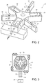
- the central electronic unit 2 also comprises a processing unit 20 ( Figure 3 ), which is connected to the sensor systems 12. Thus, the processing unit 20 is shared between the six load cells 6.
- the processing unit 20 is capable of determining, on the basis of the electrical signals supplied by the three corresponding sensor systems 12 and in a manner in itself known, a corresponding lateral structure vector, which includes the three components of the force acting on the corresponding load cell 6, as well as the three components of the torque acting on this load cell 6, this force and torque acting at the geometric centre of the load cell 6.
- a corresponding lateral structure vector which includes the three components of the force acting on the corresponding load cell 6, as well as the three components of the torque acting on this load cell 6, this force and torque acting at the geometric centre of the load cell 6.
- the six components of any local structure vector are determined such that they refer to the support element 8, and so that they are null when the aforesaid force and torque acting at the geometric centre of the load cell 6 are null.
- each of them comprises a central region 22 ( Figure 2 ).
- the geometric centre of each load cell 6 is therefore the centroid of the solid formed by the three corresponding spokes 10 and the corresponding central region 22.
- the central region 22 forms the central portion 26 of the corresponding load cell 6, i.e. the portion from which the spokes 10 of the load cell 6 extend.
- the central region 22 also forms three internal coupling regions 28, which form one piece with the central portion 26, and therefore with the spokes 10, and are arranged so as to define three pairs of internal coupling regions 28, each pair forming an angle of 120°. Furthermore, the internal coupling regions 28 are arranged such that each one of them is radially arranged between a corresponding pair of spokes 10 and is set apart from each of these spokes by an angular distance of 60°. In addition, each internal coupling region 28 delimits a corresponding upward-facing blind internal cavity 30.
- Each lateral structure 4 also comprises a respective protective layer 32, which is constrained to the corresponding closed support element 8, overlies the corresponding load cell 6 and defines a pass-through upper opening 33, which overlies the internal cavities 30, so as to give access to the internal cavities 30 from the outside.
- a respective protective layer 32 which is constrained to the corresponding closed support element 8, overlies the corresponding load cell 6 and defines a pass-through upper opening 33, which overlies the internal cavities 30, so as to give access to the internal cavities 30 from the outside.
- only one protective layer 32 is shown in Figure 1 .
- Each protective layer 32 performs the function of protecting the underlying portions during the phases of assembly and handling of the central electronic unit 2.
- the six lateral structures 4 are constrained such that the central electronic unit 2 assumes the form of a cube, the faces of which are formed precisely by the lateral structures 4. To this end, considering any one of the lateral structure 4, this is constrained to the four lateral structures 4 adjacent to it.
- first lateral structure shown in Figure 4 , where it is indicated by reference numeral 4'
- second lateral structure in Figure 4
- the closed support elements of the first and the second lateral structures 4' and 4" respectively form a first threaded hole 35 and a first unthreaded hole 36, which are aligned with one another, the first threaded hole 35 being pass-through and communicating with the first unthreaded hole 36.
- the first threaded hole 35 has a smaller diameter than the first unthreaded hole 36.
- the coupling screw extends through the first threaded hole 35 and the first unthreaded hole 36. More specifically, the coupling screw 34' is such as to engage the first threaded hole 35, making direct contact with the first threaded hole 35; furthermore, the coupling screw 34' is such that it engages, with play, the first unthreaded hole 36, i.e. not in contact with the walls of the first unthreaded hole 36.
- the coupling screw 34' is characterized by easier removal and insertion.
- the first lateral structure 4' is also valid for the all the other lateral structures 4 of the central electronic unit 2, and considering that the six lateral structures 6 form a polyhedral solid complete with all its faces (and therefore closed), the lateral structures 4 are consequently all constrained by each other, so as to assure the assembly of the central electronic unit 2. Furthermore, the central electronic unit 2 is assembled so as to reduce stresses inside the central electronic unit 2, these stresses generally being caused by tolerance and misalignments between the mechanical parts of the central electronic unit 2. In particular, the stresses to which the closed support elements 8, and therefore also the spokes 10, are subjected following assembly of the central electronic unit 2, are reduced.
- the assembly of the central electronic unit 2 by means of the coupling screws 34 can take place by using preliminary screws 39.
- the closed support elements 8', 8" of the first and second lateral structure 4' and 4" respectively form a second unthreaded hole 37 and a second threaded hole 38, which are aligned with one another, the second unthreaded hole 37 being pass-through and communicating with the second threaded hole 38.
- the second threaded hole 38 has a smaller diameter than the second unthreaded hole 37.
- the preliminary screw 39 passes in the second unthreaded hole 37 with play, while it couples with the second threaded hole 38. Furthermore, the head of the preliminary screw 39 touches the closed support element 8' of the first lateral structure 4', so as to constrain it to the closed support element 8" of the second lateral structure 4".
- the first and second lateral structures 4' and 4" are fastened to one another and so insertion of the coupling screw 34' is facilitated. Once the coupling screw 34' is inserted, the preliminary screw 39 is removed.
- the preliminary screws 39 are also shown, although, as explained, they are preferably absent once assembly of the central electronic unit 2 is finished.
- the coupling screws 34 and the preliminary screws 39 are parallel to one another and are arranged so as to form four pairs of screws, each pair being arranged close to a respective vertex of a square defined by the corresponding closed support element 8.
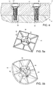
- the polymorphous device 1 comprises six external covering elements 40 ( Figures 5a-5d ), each of which is electrically passive and suitable for being mechanically coupled to a corresponding lateral structure 4, and therefore to a corresponding load cell 6.
- each external covering element 40 can be coupled to the corresponding central region 22, by using a fastening screw 42.
- each central region 22 forms a fastening cavity 43, which is threaded and can be engaged by a corresponding fastening screw 42.
- the geometric centre of each load cell 6 falls within the corresponding fastening cavity 43.
- the outer surfaces of the external covering elements 40 i.e. the surfaces that, in use, do not face towards the central electronic unit 2 have a shape that can be chosen from: squares ( Figure 5a ), portions of a sphere ( Figure 5b ), circles ( Figure 5c ) and portions of a cylinder ( Figure 5d ).
- each external covering element 40 forms an external coupling region 48, which faces towards the corresponding lateral structure 4 when the external covering element 40 is coupled to the central electronic unit 2.
- the external region 48 extends through the upper opening 33 defined by the corresponding protective layer 32, to couple with the underlying central region 22.
- the external coupling region 48 forms three protrusions 50, each of which has a parallelepipedal shape and can be housed inside a corresponding internal cavity 30, when the external covering element 40 is coupled to the central electronic unit 2, thus touching the internal coupling regions 28 and therefore the central region 22.
- the protrusions 50 also enable easily aligning the external covering element 40 with the underlying lateral structure 4, so that it assumes a predetermined position with respect to the latter.
- Coupling external covering elements 40 of opportune shape to the central electronic unit 2 produces a contact surface 60 of the polymorphous device 1, which is formed by the set of outer surfaces of the external covering elements 40 and, unlike the underlying central electronic unit 2, can be directly manipulated by a user. Therefore, the contact surface 60 prevents the user from accessing the central electronic unit 2; in addition, the contact surface 60 is at least locally curved.
- the contact surface 60 can assume a shape chosen from a cubical surface, a spherical surface and a cylindrical surface.
- the cubical surface may have a side 5 cm long; the spherical surface may have a diameter of 7 cm, and the cylindrical surface may have a diameter of 7 cm and a length of 12 cm.
- the overall weight of the polymorphous device 1 is, for example, less than three hundred grams.
- this external covering element 40 In use, assuming that a user touches the contact surface 60, and therefore applies an external force at a point of contact of a given external covering element 40, this external covering element 40, in turn, transmits a force to the corresponding load cell 6, through the corresponding fastening screw 42 and its protrusions 50.
- the processing unit 20 determines the corresponding lateral structure vector, on the basis of the electrical signals supplied by the corresponding load cell 6.
- This lateral structure vector comprises three components of an internal force, which acts on the geometric centre of the corresponding load cell 6, as well as the three components of the torque acting on the geometric centre of that load cell 6.
- the processing unit 20 is further configured to determine, on the basis of the aforesaid lateral structure vector and the (known) shape of the external covering element 40, the point of contact, as well as the external force.
- the processing unit 20 can implement the algorithms described, for example, by A. Bicchi, J. K. Salisbury, et al., in "Contact Sensing from Force Measurements", International Journal of Robotics Research 12, pages 249-252 , or the algorithms implemented in so-called force plates.
- the processing unit is then able to determine, for each external covering element 40, an external force applied to it, as well as the corresponding point of application. In the case where multiple external forces are applied to a given external covering element 40, the processing unit 20 determines the net force.
- Information regarding the quantities determined by the processing unit 20 is made available, for example, to an external computer (not shown), to which the electronic processing unit 20 can be connected.
- the central electronic unit 2 comprises, for each load cell 6, a printed-circuit board (PCB) 70, which is soldered onto the central portion 26 and the internal coupling regions 28 of the load cell 6, in order to achieve greater constructional simplicity.
- the PCB 70 has conductive tracks 72 that are electrically connected to the strain gauges 14 inside the sensor systems 12 by the interposition of conductive wires 76.
- two strain gauges 14, two conductive tracks 72 and two conductive wires 76 are shown in Figure 3 .
- the PCB 70 further comprises a flexible bus 78, inside which the conductive tracks 72 run.
- the flexible bus 78 is in turn connected to the processing unit 20, so as to electrically connect the strain gauges 14 to the processing unit 20 in a simple and reliable manner. In this way, possible maintenance and disassembly operations on the central electronic unit 2, as well as routing operations on the electrical paths, are also facilitated.
- each load cell 6 comprises three protection pins 80, each of which corresponds to a respective internal coupling region 28.
- each protection pin 80 is shown in Figure 2 .
- the corresponding protection pin 80 passes through the corresponding closed support element 8, inside which it is press fitted. Furthermore, the protection pin 80 protrudes beyond the closed support element 8, so as to extend inside a protective cavity 90 formed inside the internal coupling region 28 and different from the internal cavity 30 defined by the same internal coupling region 28.
- the protective cavity 90 is a cylindrically shaped blind hole, with a diameter such that when the load cell 6 is not deformed, the protection pin 80 extends with play inside the protective cavity 90. Therefore, in the absence of deformation, or in the presence of deformations below a threshold value, the protection pin 80 does not touch with the corresponding internal coupling region 28.
- the protection pin 80 touches the walls of the protective cavity 90, and therefore becomes coupled with the internal coupling region 28, preventing, or in any case limiting, further deformation of this internal coupling region 28, and therefore of the load cell 6. In this way, overload situations that could damage the load cell 6 are avoided.
- the present polymorphous device has a single electronic unit, which can be coupled with different external covering elements, so as to produce an interaction surface having opportune geometry, according to needs, without modifying the underlying electronic unit.
- the present polymorphous device is therefore characterized, amongst other things, by low operating costs and high flexibility of use.
- the present polymorphous device enables determining the forces and torques acting on the device, as well as the corresponding points of application of these forces.
- the central electronic unit could be formed by a different number of lateral structures.
- the central electronic unit could be formed by four lateral structures, arranged so as to form a tetrahedron.
- corresponding pins could be present.
- the lateral structures form the faces of any polyhedral solid, preferably, but not necessarily, complete with all of its faces.
- the central electronic unit could be equipped with inertial sensors and/or accelerometers for the purpose of providing further information regarding the manipulation of the polymorphous device.
- the central electronic unit could comprise a battery and a wireless communications module to enable transmission of the data it has computed.
- external covering elements may be coarse, at least in part, to facilitate grasping.
- they may be made, at least in part, of a polymeric material.
- one or more external covering elements may be formed, at least in part, by tactile sensors, for example of a type chosen from: resistive, conductive, capacitive, piezoelectric, barometric, etc.
- each tactile sensor can function in on/off mode, so as to enable the detection of multiple contact points, or in continuous mode, in order to measure the pressure exerted during grasping.
- each load cell may be of a different type. Each one of them may therefore comprise a different number of spokes and sensor systems of a different type; for example, each load cell may include a different number of strain gauges, which may also be connected in a different manner to that described. Thus, embodiments are possible, for example, in which each load cell comprises only six strain gauges, which provide six electrical signals indicative of the applied load and defining a measurement with six degrees of freedom.
- the internal coupling regions and the external coupling regions may be absent, or in any case may have different shapes and arrangements with respect to that shown and described. It is also possible that one or more load cells are substituted by different sensors, which are, in any case, capable of generating electrical signals indicative of deformation of the corresponding support structures.
- an external covering element may be made integral with a fixed surface (not shown), in which case the polymorphous device provides measurements of the forces and torques applied to the device, with reference to the fixed surface, these measurements being provided by the load cell that corresponds to the external covering element made integral with the fixed surface.
- the polymorphous device could be used to form a complex system suitable for being manipulated by several users.
Landscapes
- Physics & Mathematics (AREA)
- General Physics & Mathematics (AREA)
- Chemical & Material Sciences (AREA)
- Analytical Chemistry (AREA)
- Force Measurement Appropriate To Specific Purposes (AREA)
- Analysing Materials By The Use Of Radiation (AREA)
Claims (13)
- Elektronische Messeinheit für eine polymorphe Vorrichtung (1) zur Kraftmessung eines Handgriffs, mit mindestens vier seitlichen Strukturen (4), wobei jede seitliche Struktur aufweist:eine Tragstruktur (8, 10, 22, 26, 28);mindestens einen Sensor (12, 14), der an der Tragstruktur befestigt und dafür konfiguriert ist, ein elektrisches Signal zu erzeugen, das eine Verformung der Tragstruktur anzeigt; undeine Verbindungseinrichtung (43), die dafür konfiguriert ist, ein entsprechendes durch einen Benutzer manipulierbares externes Abdeckelement (40) auf eine lösbare Weise an der Tragstruktur zu befestigen, so dass, wenn das entsprechende externe Abdeckelement an der Tragstruktur befestigt ist und eine äußere Kraft auf das entsprechende äußere Abdeckelement einwirkt, das elektrische Signal die äußere Kraft anzeigt,wobei die elektronische Messeinheit dadurch gekennzeichnet ist, dass die seitlichen Strukturen (4) derart angeordnet sind, dass sie ein Polyeder bilden, und wobei jede seitliche Struktur (4') mit den diesem benachbarten seitlichen Strukturen mittels entsprechender Verbindungselemente (34') verbunden ist, wobei jedes Verbindungselement mit der Tragstruktur (8') der seitlichen Struktur verbunden ist und sich mit Spiel teilweise in einem innerhalb der Tragstruktur (8") der entsprechenden angrenzenden seitlichen Struktur (4") ausgebildeten Gehäusehohlraum (36) erstreckt.
- Elektronische Einheit nach Anspruch 1, wobei die Verbindungselemente Schrauben (34) sind, und wobei die Tragstruktur (8) jeder seitlichen Struktur (4) für jede benachbarte seitliche Struktur einen jeweiligen Gewindehohlraum (35), bildet, der mit dem entsprechenden Gehäusehohlraum (36) kommuniziert, wobei die Schraube, die sich mit Spiel in dem entsprechenden Gehäusehohlraum erstreckt, mit dem jeweiligen Gewindehohlraum verbunden ist.
- Elektronische Einheit nach einem der vorangehenden Ansprüche, ferner mit einer Verarbeitungseinheit (20), die mit den Sensoren (12, 14) verbunden und dafür konfiguriert ist, für jede seitliche Struktur (4) einen Messwert der auf das entsprechende äußere Abdeckelement (40) wirkenden äußeren Kraft zu bestimmen
- Elektronische Einheit nach Anspruch 3, wobei die Verarbeitungseinheit (20) ferner dafür konfiguriert ist, für jede seitliche Struktur (4) den Angriffspunkt der auf das entsprechende äußere Abdeckelement (40) wirkenden äußeren Kraft zu bestimmen.
- Elektronische Einheit nach Anspruch 4, wobei jede seitliche Struktur (4) eine jeweilige sechsachsige Wägezelle (6) bildet, die mehrere Speichen (10) aufweist, die miteinander verbunden sind und von einem Tragrahmen (8) umschrieben sind, an dem sie befestigt sind, und wobei die Verarbeitungseinheit (20) ferner dafür konfiguriert ist, für jede seitliche Struktur einen entsprechenden Vektor zu bestimmen, der durch drei Komponenten einer inneren Kraft und drei Komponenten eines Drehmoments gebildet wird, wobei die innere Kraft und das Drehmoment an einem Punkt der Tragstruktur (8, 10, 22, 26, 28) der seitlichen Struktur einwirken und durch die auf das entsprechende äußere Abdeckelement (40) wirkende äußere Kraft verursacht werden.
- Elektronische Einheit nach Anspruch 5, wobei die Verarbeitungseinheit (20) dafür konfiguriert ist, für jede seitliche Struktur (4) den Messwert der auf das entsprechende äußere Abdeckelement (40) einwirkenden äußeren Kraft und den Angriffspunkt der entsprechenden äußeren Kraft basierend auf dem entsprechenden Vektor zu bestimmen.
- Elektronische Einheit nach Anspruch 5 oder 6, wobei jede Wägezelle (6) mehrere Dehnungsmessstreifen (14) aufweist und ferner für jede Wägezelle eine entsprechende Leiterplatte (70) aufweist, wobei die Dehnungsmessstreifen jeder Wägezelle durch Zwischenschaltung der entsprechenden Leiterplatte elektrisch mit der Verarbeitungseinheit (20) verbunden sind.
- Elektronische Einheit nach einem der Ansprüche 5 bis 7, wobei jede Tragstruktur (8, 10, 22, 26, 28) einen entsprechenden Mittenbereich (22) bildet, an dem die entsprechenden Speichen (10) befestigt sind, wobei der Mittenbereich eine Anzahl von Kopplungshohlräumen (30) bildet, die dafür konfiguriert sind, entsprechende Vorsprünge (50) des entsprechenden externen Abdeckelements (40) aufzunehmen, wobei die Kopplungshohlräume in Bezug auf die entsprechenden Speichen (10) radial nach außen versetzt sind.
- Elektronische Einheit nach Anspruch 8, wobei jeder Mittenbereich (22) eine Anzahl innerer Kopplungsbereiche (28) bildet, von denen jeder einen entsprechenden Kopplungshohlraum (30) bildet, wobei die elektronische Einheit ferner mindestens ein Schutzelement (80) aufweist, das an einem der Tragrahmen (30) befestigt ist und sich teilweise mit Spiel in einem Schutzhohlraum (90) erstreckt, der in einem entsprechenden inneren Kopplungsbereich (28) ausgebildet ist, so dass das Schutzelement die Wände des Schutzhohlraums berührt, wenn sich der entsprechende innere Kopplungsbereich lokal über einen Verformungsschwellenwert hinausgehend verformt, wodurch eine weitere Verformung des entsprechenden inneren Kopplungsbereichs verhindert wird.
- Elektronische Einheit nach einem der vorangehenden Ansprüche, wobei die Kopplungseinrichtung einen Befestigungshohlraum (43) aufweist, der innerhalb der Tragstruktur (8, 10, 22, 26) ausgebildet und dafür konfiguriert ist, mit einer entsprechenden Befestigungsschraube (42) verbunden zu werden.
- Polymorphe Vorrichtung mit der elektronischen Messeinheit (2) nach einem der vorangehenden Ansprüche und mehreren äußeren Abdeckelementen (40), die dafür konfiguriert sind, eine durch einen Benutzer manipulierbare Kontaktfläche (60) zu bilden, wenn sie mit den entsprechenden Tragstrukturen (8, 10, 22, 26, 28) verbunden sind.
- Polymorphe Vorrichtung nach Anspruch 11, wobei die äußeren Abdeckelemente (40) derart ausgebildet sind, dass die Kontaktfläche (60) konfiguriert ist, einen Zugriff des Benutzers auf die elektronische Messeinheit (2) zu verhindern.
- Polymorphe Vorrichtung nach Anspruch 11, insofern abhängig von Anspruch 9, wobei jedes der äußeren Abdeckelemente (40) eine Anzahl von Vorsprüngen (50) aufweist, die dafür konfiguriert sind, mit den Kopplungshohlräumen (30) in Eingriff zu kommen, so dass das äußere Abdeckelement in Bezug auf die entsprechende Tragstruktur (10, 22, 26, 28) eine vorgegebene Position einnimmt.
Applications Claiming Priority (2)
| Application Number | Priority Date | Filing Date | Title |
|---|---|---|---|
| IT000890A ITTO20120890A1 (it) | 2012-10-11 | 2012-10-11 | Unita' elettronica di misura per un dispositivo polimorfico per la misura di forze, e dispositivo polimorfico includente la medesima |
| PCT/IB2013/059323 WO2014057479A2 (en) | 2012-10-11 | 2013-10-11 | Electronic measurement unit for a polymorphous device for force measurement and polymorphous device including the same |
Publications (2)
| Publication Number | Publication Date |
|---|---|
| EP2906920A2 EP2906920A2 (de) | 2015-08-19 |
| EP2906920B1 true EP2906920B1 (de) | 2020-03-18 |
Family
ID=47278470
Family Applications (1)
| Application Number | Title | Priority Date | Filing Date |
|---|---|---|---|
| EP13812116.5A Active EP2906920B1 (de) | 2012-10-11 | 2013-10-11 | Elektronische messeinheit für eine polymorphe vorrichtung zur kraftmessung und polymorphe vorrichtung damit |
Country Status (5)
| Country | Link |
|---|---|
| US (1) | US9719868B2 (de) |
| EP (1) | EP2906920B1 (de) |
| CN (1) | CN104919291B (de) |
| IT (1) | ITTO20120890A1 (de) |
| WO (1) | WO2014057479A2 (de) |
Families Citing this family (14)
| Publication number | Priority date | Publication date | Assignee | Title |
|---|---|---|---|---|
| DE102015104410B4 (de) * | 2015-03-24 | 2018-09-13 | Tdk-Micronas Gmbh | Drucksensor |
| GB201617097D0 (en) * | 2016-10-07 | 2016-11-23 | King S College London | Multi-Axis force sensor |
| EP3526565A1 (de) * | 2016-10-17 | 2019-08-21 | Kistler Holding AG | Kraft- und momentensensor, kraftaufnehmermodul für einen solchen kraft- und momentensensor und roboter mit einem solchen kraft- und momentensensor |
| DE112019002964T5 (de) * | 2018-06-14 | 2021-02-25 | Sintokogio, Ltd. | Dehnungselement, Verfahren zum Herstellen von Dehnungselementen und Sensor zum Messen physikalischer Größen |
| JP7207886B2 (ja) * | 2018-07-26 | 2023-01-18 | キヤノン株式会社 | センサ、センサの制御方法、ロボットハンド、ロボットハンドの制御方法、ロボット装置、ロボット装置を用いた物品の制御方法、構造体、制御プログラムおよび記録媒体 |
| CN110857896B (zh) * | 2018-08-10 | 2023-05-02 | 新东工业株式会社 | 力传感器 |
| TWI716789B (zh) * | 2018-12-20 | 2021-01-21 | 財團法人工業技術研究院 | 多軸力感測裝置 |
| JP7262320B2 (ja) * | 2019-06-18 | 2023-04-21 | アズビル株式会社 | モーメントセンサ |
| JP2020204565A (ja) * | 2019-06-18 | 2020-12-24 | アズビル株式会社 | モーメントセンサ |
| JP2020204562A (ja) * | 2019-06-18 | 2020-12-24 | アズビル株式会社 | モーメントセンサ |
| JP2020204564A (ja) * | 2019-06-18 | 2020-12-24 | アズビル株式会社 | モーメントセンサ |
| CN110793700B (zh) * | 2019-10-30 | 2021-07-16 | 中国空空导弹研究院 | 一种六轴向组合按压传感器 |
| CN111780836B (zh) * | 2020-07-08 | 2021-09-14 | 浙江佳鹏电脑科技股份有限公司 | 应变桥、包含应变桥的弹性变量测量单元及其安装方法 |
| JP7592957B2 (ja) * | 2020-12-24 | 2024-12-03 | ミネベアミツミ株式会社 | センサチップ、力覚センサ装置 |
Citations (2)
| Publication number | Priority date | Publication date | Assignee | Title |
|---|---|---|---|---|
| JPS6093933A (ja) * | 1983-10-28 | 1985-05-25 | Fuji Electric Corp Res & Dev Ltd | 荷重計 |
| EP0611958A2 (de) * | 1993-02-15 | 1994-08-24 | Japan Electronics Industry, Ltd. | Ausgesuchte Trägerstelle für einen Belastungssensor einer Vorrichtung zur Messung der Krafteinwirkung auf ein Rad |
Family Cites Families (27)
| Publication number | Priority date | Publication date | Assignee | Title |
|---|---|---|---|---|
| US3904234A (en) * | 1973-10-15 | 1975-09-09 | Stanford Research Inst | Manipulator with electromechanical transducer means |
| US3948093A (en) * | 1975-06-30 | 1976-04-06 | International Business Machines Corporation | Six degree of freedom force transducer for a manipulator system |
| US4640138A (en) * | 1985-03-06 | 1987-02-03 | Mts Systems Corporation | Multiple axis load sensitive transducer |
| DE3611336A1 (de) * | 1986-04-04 | 1987-10-15 | Deutsche Forsch Luft Raumfahrt | Kraft-drehmoment-fuehler |
| JP3141954B2 (ja) * | 1991-07-17 | 2001-03-07 | 株式会社ワコー | 圧電素子を用いた力・加速度・磁気のセンサ |
| JP3131642B2 (ja) * | 1994-09-14 | 2001-02-05 | 日本電子工業株式会社 | 応力複合化センサ及びこれを用いた構造体の応力測定装置 |
| US5490427A (en) * | 1994-10-17 | 1996-02-13 | Fanuc Usa Corporation | Six axis force sensor employing multiple shear strain gages |
| US5648617A (en) * | 1995-08-25 | 1997-07-15 | Applied Robotics, Inc. | Single axis robot force sensor assembly |
| US5526700A (en) * | 1995-09-29 | 1996-06-18 | Akeel; Hadi A. | Six component force gage |
| KR100199691B1 (ko) * | 1997-05-19 | 1999-06-15 | 김동진 | 6분력 로드셀 |
| JP3261653B2 (ja) * | 1999-07-07 | 2002-03-04 | 独立行政法人産業技術総合研究所 | 指装着型6軸力覚センサ |
| WO2002048875A2 (en) * | 2000-12-15 | 2002-06-20 | Mts Systems Corporation | Multi-axis load cell |
| ITMI20031500A1 (it) | 2003-07-22 | 2005-01-23 | Milano Politecnico | Dispositivo e metodo per la misura di forze e momenti |
| JP2005241470A (ja) * | 2004-02-26 | 2005-09-08 | Denso Corp | タイヤ作用力検出装置及びタイヤ作用力検出方法 |
| GB0417683D0 (en) * | 2004-08-09 | 2004-09-08 | C13 Ltd | Sensor |
| DE102005033527B4 (de) * | 2005-07-14 | 2009-07-16 | Schenck Process Gmbh | Vorrichtung zur Erfassung von Kräften und/oder Momenten |
| US7743672B2 (en) * | 2008-06-06 | 2010-06-29 | Kulite Semiconductor Products, Inc. | Multiple axis load cell controller |
| JP4912477B2 (ja) * | 2010-02-02 | 2012-04-11 | 公立大学法人高知工科大学 | 移動型床反力計測装置 |
| EP2422935B1 (de) * | 2010-08-31 | 2015-02-25 | Kabushiki Kaisha Yaskawa Denki | Roboter, Robotersystem, Robotersteuerungsvorrichtung und Statusbestimmungsverfahren |
| JP2012088263A (ja) * | 2010-10-22 | 2012-05-10 | Seiko Epson Corp | 検出装置、電子機器及びロボット |
| JP2012122823A (ja) * | 2010-12-08 | 2012-06-28 | Seiko Epson Corp | 検出装置、電子機器、及びロボット |
| JP2012163333A (ja) * | 2011-02-03 | 2012-08-30 | Seiko Epson Corp | 検出装置、電子機器及びロボット |
| JP5836633B2 (ja) * | 2011-05-10 | 2015-12-24 | キヤノン株式会社 | 力覚センサ及び組立ロボット |
| JP5880934B2 (ja) * | 2011-12-20 | 2016-03-09 | セイコーエプソン株式会社 | センサーデバイス、センサーモジュール、力検出装置、ロボット |
| JP5880935B2 (ja) * | 2011-12-20 | 2016-03-09 | セイコーエプソン株式会社 | センサーデバイス、センサーモジュール、ロボット、センサーデバイスの製造方法 |
| JP5895615B2 (ja) * | 2012-03-09 | 2016-03-30 | セイコーエプソン株式会社 | センサーモジュール、力検出装置及びロボット |
| JP2015184005A (ja) * | 2014-03-20 | 2015-10-22 | セイコーエプソン株式会社 | 力検出装置、およびロボット |
-
2012
- 2012-10-11 IT IT000890A patent/ITTO20120890A1/it unknown
-
2013
- 2013-10-11 EP EP13812116.5A patent/EP2906920B1/de active Active
- 2013-10-11 CN CN201380053477.XA patent/CN104919291B/zh not_active Expired - Fee Related
- 2013-10-11 WO PCT/IB2013/059323 patent/WO2014057479A2/en not_active Ceased
- 2013-10-11 US US14/435,154 patent/US9719868B2/en not_active Expired - Fee Related
Patent Citations (2)
| Publication number | Priority date | Publication date | Assignee | Title |
|---|---|---|---|---|
| JPS6093933A (ja) * | 1983-10-28 | 1985-05-25 | Fuji Electric Corp Res & Dev Ltd | 荷重計 |
| EP0611958A2 (de) * | 1993-02-15 | 1994-08-24 | Japan Electronics Industry, Ltd. | Ausgesuchte Trägerstelle für einen Belastungssensor einer Vorrichtung zur Messung der Krafteinwirkung auf ein Rad |
Non-Patent Citations (1)
| Title |
|---|
| BOURAUEL C ET AL: "KRAFT-MOMENTEN-AUFNEHMER FUER DIE KIEFERORTHOPAEDIE", FEINWERKTECHNIK + MESSTECHNIK, HANSER, MUNCHEN, DE, vol. 98, no. 10, 1 October 1990 (1990-10-01), pages 419 - 422, XP000165963, ISSN: 0340-1952 * |
Also Published As
| Publication number | Publication date |
|---|---|
| US9719868B2 (en) | 2017-08-01 |
| CN104919291A (zh) | 2015-09-16 |
| EP2906920A2 (de) | 2015-08-19 |
| WO2014057479A2 (en) | 2014-04-17 |
| ITTO20120890A1 (it) | 2014-04-12 |
| US20150233774A1 (en) | 2015-08-20 |
| WO2014057479A3 (en) | 2014-06-12 |
| CN104919291B (zh) | 2017-07-21 |
Similar Documents
| Publication | Publication Date | Title |
|---|---|---|
| US9719868B2 (en) | Electronic measurement unit for a polymorphous device for force measurement and polymorphous device including the same | |
| CN110871460B (zh) | 传感器单元、传感器系统、机械手、机械臂、服务器装置 | |
| KR101115418B1 (ko) | 힘센서를 이용한 6축 힘센서 구조 및 그 구조에 의한 힘 및 모멘트 측정방법 | |
| EP1782030B1 (de) | Vollachsensensor zur erkennung von eingangskraft und -drehmoment | |
| Li et al. | Multiaxis force/torque sensor technologies: Design principles and robotic force control applications: A review | |
| US20200030981A1 (en) | Robot and abnormality detection method of robot | |
| JPS6034295A (ja) | 皮膚感覚センサ | |
| Choi et al. | A soft three-axis force sensor based on radially symmetric pneumatic chambers | |
| CN104205022B (zh) | 操作位置检测装置和车载装置 | |
| WO2016126821A1 (en) | Force/torque transducer and method of operating the same | |
| WO2016145011A1 (en) | Soft-body deformation and force sensing | |
| Kim et al. | High-stiffness torque sensor with a strain amplification mechanism for cooperative industrial manipulators | |
| US8265792B2 (en) | Method and apparatus for calibrating multi-axis load cells in a dexterous robot | |
| Park et al. | Tactile sensor integrated fingertip capable of detecting precise contact force for robotic grippers | |
| Park et al. | Three-axis flat and lightweight force/torque sensor for enhancing kinesthetic sensing capability of robotic hand | |
| KR20110098070A (ko) | 6축 힘-모멘트 감지센서 | |
| KR101310012B1 (ko) | 복합형 다축센서 | |
| EP4469248B1 (de) | Sensorisierter finger für einen greifer | |
| JP5318831B2 (ja) | 操作位置検出装置 | |
| JP2010112864A (ja) | 力センサー | |
| WO2018135416A1 (ja) | 身体部位接触力センサ | |
| Nasir et al. | Calibration of embedded force sensor for robotic hand manipulation | |
| CN223903954U (zh) | 一种机械手爪传感装置 | |
| KR100597558B1 (ko) | 스트레인 게이지를 이용한 zmp감지장치 및 그 감지방법 | |
| Fritzsche et al. | A tactile sensor with cushioning elements for enhanced safety in human-robot interaction |
Legal Events
| Date | Code | Title | Description |
|---|---|---|---|
| PUAI | Public reference made under article 153(3) epc to a published international application that has entered the european phase |
Free format text: ORIGINAL CODE: 0009012 |
|
| 17P | Request for examination filed |
Effective date: 20150415 |
|
| AK | Designated contracting states |
Kind code of ref document: A2 Designated state(s): AL AT BE BG CH CY CZ DE DK EE ES FI FR GB GR HR HU IE IS IT LI LT LU LV MC MK MT NL NO PL PT RO RS SE SI SK SM TR |
|
| AX | Request for extension of the european patent |
Extension state: BA ME |
|
| DAX | Request for extension of the european patent (deleted) | ||
| GRAP | Despatch of communication of intention to grant a patent |
Free format text: ORIGINAL CODE: EPIDOSNIGR1 |
|
| STAA | Information on the status of an ep patent application or granted ep patent |
Free format text: STATUS: GRANT OF PATENT IS INTENDED |
|
| INTG | Intention to grant announced |
Effective date: 20190730 |
|
| GRAJ | Information related to disapproval of communication of intention to grant by the applicant or resumption of examination proceedings by the epo deleted |
Free format text: ORIGINAL CODE: EPIDOSDIGR1 |
|
| GRAS | Grant fee paid |
Free format text: ORIGINAL CODE: EPIDOSNIGR3 |
|
| GRAJ | Information related to disapproval of communication of intention to grant by the applicant or resumption of examination proceedings by the epo deleted |
Free format text: ORIGINAL CODE: EPIDOSDIGR1 |
|
| GRAL | Information related to payment of fee for publishing/printing deleted |
Free format text: ORIGINAL CODE: EPIDOSDIGR3 |
|
| STAA | Information on the status of an ep patent application or granted ep patent |
Free format text: STATUS: REQUEST FOR EXAMINATION WAS MADE |
|
| INTC | Intention to grant announced (deleted) | ||
| GRAR | Information related to intention to grant a patent recorded |
Free format text: ORIGINAL CODE: EPIDOSNIGR71 |
|
| STAA | Information on the status of an ep patent application or granted ep patent |
Free format text: STATUS: GRANT OF PATENT IS INTENDED |
|
| GRAA | (expected) grant |
Free format text: ORIGINAL CODE: 0009210 |
|
| STAA | Information on the status of an ep patent application or granted ep patent |
Free format text: STATUS: THE PATENT HAS BEEN GRANTED |
|
| INTG | Intention to grant announced |
Effective date: 20200205 |
|
| AK | Designated contracting states |
Kind code of ref document: B1 Designated state(s): AL AT BE BG CH CY CZ DE DK EE ES FI FR GB GR HR HU IE IS IT LI LT LU LV MC MK MT NL NO PL PT RO RS SE SI SK SM TR |
|
| REG | Reference to a national code |
Ref country code: GB Ref legal event code: FG4D |
|
| REG | Reference to a national code |
Ref country code: DE Ref legal event code: R096 Ref document number: 602013067004 Country of ref document: DE |
|
| REG | Reference to a national code |
Ref country code: AT Ref legal event code: REF Ref document number: 1246449 Country of ref document: AT Kind code of ref document: T Effective date: 20200415 Ref country code: IE Ref legal event code: FG4D |
|
| PG25 | Lapsed in a contracting state [announced via postgrant information from national office to epo] |
Ref country code: RS Free format text: LAPSE BECAUSE OF FAILURE TO SUBMIT A TRANSLATION OF THE DESCRIPTION OR TO PAY THE FEE WITHIN THE PRESCRIBED TIME-LIMIT Effective date: 20200318 Ref country code: FI Free format text: LAPSE BECAUSE OF FAILURE TO SUBMIT A TRANSLATION OF THE DESCRIPTION OR TO PAY THE FEE WITHIN THE PRESCRIBED TIME-LIMIT Effective date: 20200318 Ref country code: NO Free format text: LAPSE BECAUSE OF FAILURE TO SUBMIT A TRANSLATION OF THE DESCRIPTION OR TO PAY THE FEE WITHIN THE PRESCRIBED TIME-LIMIT Effective date: 20200618 |
|
| REG | Reference to a national code |
Ref country code: NL Ref legal event code: MP Effective date: 20200318 |
|
| PG25 | Lapsed in a contracting state [announced via postgrant information from national office to epo] |
Ref country code: LV Free format text: LAPSE BECAUSE OF FAILURE TO SUBMIT A TRANSLATION OF THE DESCRIPTION OR TO PAY THE FEE WITHIN THE PRESCRIBED TIME-LIMIT Effective date: 20200318 Ref country code: SE Free format text: LAPSE BECAUSE OF FAILURE TO SUBMIT A TRANSLATION OF THE DESCRIPTION OR TO PAY THE FEE WITHIN THE PRESCRIBED TIME-LIMIT Effective date: 20200318 Ref country code: HR Free format text: LAPSE BECAUSE OF FAILURE TO SUBMIT A TRANSLATION OF THE DESCRIPTION OR TO PAY THE FEE WITHIN THE PRESCRIBED TIME-LIMIT Effective date: 20200318 Ref country code: GR Free format text: LAPSE BECAUSE OF FAILURE TO SUBMIT A TRANSLATION OF THE DESCRIPTION OR TO PAY THE FEE WITHIN THE PRESCRIBED TIME-LIMIT Effective date: 20200619 Ref country code: BG Free format text: LAPSE BECAUSE OF FAILURE TO SUBMIT A TRANSLATION OF THE DESCRIPTION OR TO PAY THE FEE WITHIN THE PRESCRIBED TIME-LIMIT Effective date: 20200618 |
|
| REG | Reference to a national code |
Ref country code: LT Ref legal event code: MG4D |
|
| PG25 | Lapsed in a contracting state [announced via postgrant information from national office to epo] |
Ref country code: NL Free format text: LAPSE BECAUSE OF FAILURE TO SUBMIT A TRANSLATION OF THE DESCRIPTION OR TO PAY THE FEE WITHIN THE PRESCRIBED TIME-LIMIT Effective date: 20200318 |
|
| PG25 | Lapsed in a contracting state [announced via postgrant information from national office to epo] |
Ref country code: IS Free format text: LAPSE BECAUSE OF FAILURE TO SUBMIT A TRANSLATION OF THE DESCRIPTION OR TO PAY THE FEE WITHIN THE PRESCRIBED TIME-LIMIT Effective date: 20200718 Ref country code: SK Free format text: LAPSE BECAUSE OF FAILURE TO SUBMIT A TRANSLATION OF THE DESCRIPTION OR TO PAY THE FEE WITHIN THE PRESCRIBED TIME-LIMIT Effective date: 20200318 Ref country code: SM Free format text: LAPSE BECAUSE OF FAILURE TO SUBMIT A TRANSLATION OF THE DESCRIPTION OR TO PAY THE FEE WITHIN THE PRESCRIBED TIME-LIMIT Effective date: 20200318 Ref country code: RO Free format text: LAPSE BECAUSE OF FAILURE TO SUBMIT A TRANSLATION OF THE DESCRIPTION OR TO PAY THE FEE WITHIN THE PRESCRIBED TIME-LIMIT Effective date: 20200318 Ref country code: EE Free format text: LAPSE BECAUSE OF FAILURE TO SUBMIT A TRANSLATION OF THE DESCRIPTION OR TO PAY THE FEE WITHIN THE PRESCRIBED TIME-LIMIT Effective date: 20200318 Ref country code: CZ Free format text: LAPSE BECAUSE OF FAILURE TO SUBMIT A TRANSLATION OF THE DESCRIPTION OR TO PAY THE FEE WITHIN THE PRESCRIBED TIME-LIMIT Effective date: 20200318 Ref country code: PT Free format text: LAPSE BECAUSE OF FAILURE TO SUBMIT A TRANSLATION OF THE DESCRIPTION OR TO PAY THE FEE WITHIN THE PRESCRIBED TIME-LIMIT Effective date: 20200812 Ref country code: LT Free format text: LAPSE BECAUSE OF FAILURE TO SUBMIT A TRANSLATION OF THE DESCRIPTION OR TO PAY THE FEE WITHIN THE PRESCRIBED TIME-LIMIT Effective date: 20200318 |
|
| REG | Reference to a national code |
Ref country code: AT Ref legal event code: MK05 Ref document number: 1246449 Country of ref document: AT Kind code of ref document: T Effective date: 20200318 |
|
| REG | Reference to a national code |
Ref country code: DE Ref legal event code: R097 Ref document number: 602013067004 Country of ref document: DE |
|
| PLBE | No opposition filed within time limit |
Free format text: ORIGINAL CODE: 0009261 |
|
| STAA | Information on the status of an ep patent application or granted ep patent |
Free format text: STATUS: NO OPPOSITION FILED WITHIN TIME LIMIT |
|
| PG25 | Lapsed in a contracting state [announced via postgrant information from national office to epo] |
Ref country code: DK Free format text: LAPSE BECAUSE OF FAILURE TO SUBMIT A TRANSLATION OF THE DESCRIPTION OR TO PAY THE FEE WITHIN THE PRESCRIBED TIME-LIMIT Effective date: 20200318 Ref country code: AT Free format text: LAPSE BECAUSE OF FAILURE TO SUBMIT A TRANSLATION OF THE DESCRIPTION OR TO PAY THE FEE WITHIN THE PRESCRIBED TIME-LIMIT Effective date: 20200318 Ref country code: ES Free format text: LAPSE BECAUSE OF FAILURE TO SUBMIT A TRANSLATION OF THE DESCRIPTION OR TO PAY THE FEE WITHIN THE PRESCRIBED TIME-LIMIT Effective date: 20200318 |
|
| 26N | No opposition filed |
Effective date: 20201221 |
|
| PG25 | Lapsed in a contracting state [announced via postgrant information from national office to epo] |
Ref country code: PL Free format text: LAPSE BECAUSE OF FAILURE TO SUBMIT A TRANSLATION OF THE DESCRIPTION OR TO PAY THE FEE WITHIN THE PRESCRIBED TIME-LIMIT Effective date: 20200318 |
|
| PG25 | Lapsed in a contracting state [announced via postgrant information from national office to epo] |
Ref country code: SI Free format text: LAPSE BECAUSE OF FAILURE TO SUBMIT A TRANSLATION OF THE DESCRIPTION OR TO PAY THE FEE WITHIN THE PRESCRIBED TIME-LIMIT Effective date: 20200318 |
|
| REG | Reference to a national code |
Ref country code: CH Ref legal event code: PL |
|
| PG25 | Lapsed in a contracting state [announced via postgrant information from national office to epo] |
Ref country code: MC Free format text: LAPSE BECAUSE OF FAILURE TO SUBMIT A TRANSLATION OF THE DESCRIPTION OR TO PAY THE FEE WITHIN THE PRESCRIBED TIME-LIMIT Effective date: 20200318 Ref country code: LU Free format text: LAPSE BECAUSE OF NON-PAYMENT OF DUE FEES Effective date: 20201011 |
|
| REG | Reference to a national code |
Ref country code: BE Ref legal event code: MM Effective date: 20201031 |
|
| PG25 | Lapsed in a contracting state [announced via postgrant information from national office to epo] |
Ref country code: BE Free format text: LAPSE BECAUSE OF NON-PAYMENT OF DUE FEES Effective date: 20201031 Ref country code: CH Free format text: LAPSE BECAUSE OF NON-PAYMENT OF DUE FEES Effective date: 20201031 Ref country code: LI Free format text: LAPSE BECAUSE OF NON-PAYMENT OF DUE FEES Effective date: 20201031 |
|
| PG25 | Lapsed in a contracting state [announced via postgrant information from national office to epo] |
Ref country code: IE Free format text: LAPSE BECAUSE OF NON-PAYMENT OF DUE FEES Effective date: 20201011 |
|
| PG25 | Lapsed in a contracting state [announced via postgrant information from national office to epo] |
Ref country code: TR Free format text: LAPSE BECAUSE OF FAILURE TO SUBMIT A TRANSLATION OF THE DESCRIPTION OR TO PAY THE FEE WITHIN THE PRESCRIBED TIME-LIMIT Effective date: 20200318 Ref country code: MT Free format text: LAPSE BECAUSE OF FAILURE TO SUBMIT A TRANSLATION OF THE DESCRIPTION OR TO PAY THE FEE WITHIN THE PRESCRIBED TIME-LIMIT Effective date: 20200318 Ref country code: CY Free format text: LAPSE BECAUSE OF FAILURE TO SUBMIT A TRANSLATION OF THE DESCRIPTION OR TO PAY THE FEE WITHIN THE PRESCRIBED TIME-LIMIT Effective date: 20200318 |
|
| PG25 | Lapsed in a contracting state [announced via postgrant information from national office to epo] |
Ref country code: MK Free format text: LAPSE BECAUSE OF FAILURE TO SUBMIT A TRANSLATION OF THE DESCRIPTION OR TO PAY THE FEE WITHIN THE PRESCRIBED TIME-LIMIT Effective date: 20200318 Ref country code: AL Free format text: LAPSE BECAUSE OF FAILURE TO SUBMIT A TRANSLATION OF THE DESCRIPTION OR TO PAY THE FEE WITHIN THE PRESCRIBED TIME-LIMIT Effective date: 20200318 |
|
| P01 | Opt-out of the competence of the unified patent court (upc) registered |
Effective date: 20230414 |
|
| PGFP | Annual fee paid to national office [announced via postgrant information from national office to epo] |
Ref country code: GB Payment date: 20231024 Year of fee payment: 11 |
|
| PGFP | Annual fee paid to national office [announced via postgrant information from national office to epo] |
Ref country code: IT Payment date: 20231003 Year of fee payment: 11 Ref country code: FR Payment date: 20231026 Year of fee payment: 11 Ref country code: DE Payment date: 20231027 Year of fee payment: 11 |
|
| REG | Reference to a national code |
Ref country code: DE Ref legal event code: R119 Ref document number: 602013067004 Country of ref document: DE |
|
| GBPC | Gb: european patent ceased through non-payment of renewal fee |
Effective date: 20241011 |
|
| PG25 | Lapsed in a contracting state [announced via postgrant information from national office to epo] |
Ref country code: DE Free format text: LAPSE BECAUSE OF NON-PAYMENT OF DUE FEES Effective date: 20250501 |
|
| PG25 | Lapsed in a contracting state [announced via postgrant information from national office to epo] |
Ref country code: GB Free format text: LAPSE BECAUSE OF NON-PAYMENT OF DUE FEES Effective date: 20241011 |
|
| PG25 | Lapsed in a contracting state [announced via postgrant information from national office to epo] |
Ref country code: FR Free format text: LAPSE BECAUSE OF NON-PAYMENT OF DUE FEES Effective date: 20241031 |
|
| PG25 | Lapsed in a contracting state [announced via postgrant information from national office to epo] |
Ref country code: IT Free format text: LAPSE BECAUSE OF NON-PAYMENT OF DUE FEES Effective date: 20241011 |