EP2906891B1 - Werkstückträger - Google Patents
Werkstückträger Download PDFInfo
- Publication number
- EP2906891B1 EP2906891B1 EP13779775.9A EP13779775A EP2906891B1 EP 2906891 B1 EP2906891 B1 EP 2906891B1 EP 13779775 A EP13779775 A EP 13779775A EP 2906891 B1 EP2906891 B1 EP 2906891B1
- Authority
- EP
- European Patent Office
- Prior art keywords
- cfc
- latching
- workpiece support
- support according
- latched
- Prior art date
- Legal status (The legal status is an assumption and is not a legal conclusion. Google has not performed a legal analysis and makes no representation as to the accuracy of the status listed.)
- Not-in-force
Links
Images


Classifications
-
- F—MECHANICAL ENGINEERING; LIGHTING; HEATING; WEAPONS; BLASTING
- F27—FURNACES; KILNS; OVENS; RETORTS
- F27D—DETAILS OR ACCESSORIES OF FURNACES, KILNS, OVENS OR RETORTS, IN SO FAR AS THEY ARE OF KINDS OCCURRING IN MORE THAN ONE KIND OF FURNACE
- F27D5/00—Supports, screens or the like for the charge within the furnace
- F27D5/0006—Composite supporting structures
-
- C—CHEMISTRY; METALLURGY
- C21—METALLURGY OF IRON
- C21D—MODIFYING THE PHYSICAL STRUCTURE OF FERROUS METALS; GENERAL DEVICES FOR HEAT TREATMENT OF FERROUS OR NON-FERROUS METALS OR ALLOYS; MAKING METAL MALLEABLE, e.g. BY DECARBURISATION OR TEMPERING
- C21D9/00—Heat treatment, e.g. annealing, hardening, quenching or tempering, adapted for particular articles; Furnaces therefor
- C21D9/0006—Details, accessories not peculiar to any of the following furnaces
- C21D9/0025—Supports; Baskets; Containers; Covers
Definitions
- the present invention relates to a workpiece carrier comprising at least two component elements, which are each composed of a carbon fiber reinforced carbon (CFC).
- CFC carbon fiber reinforced carbon
- CFC workpiece carriers are used to support or hold workpieces in high temperature environments.
- charging racks are used as a carrier, wherein the heat treatment to be subjected to workpieces are placed on a support surface of the charging frame in the simplest case.
- workpiece carriers made of CFC are characterized in particular by increased temperature resistance and better dimensional stability.
- the assembly of a workpiece carrier of a plurality of component elements is advantageous in terms of manufacturing costs and flexibility. In particular, this makes it possible to build complex frames, which are tuned to the respective workpiece type and quantity.
- the individual component elements can be plugged together, for example by means of frictional connection elements.
- a workpiece carrier for hardened material which is composed of four frame-like assembled CFC strips is, for example, in DE 295 12 569 U1 disclosed.
- At least two of the at least two CFC component elements are locked together.
- a latch engage at least two corresponding locking teeth form fit into each other and hold the two CFC component elements in a defined detent position, but under force overcoming the positive connection is possible in at least one direction. That is, when mating and possibly when pulling apart the component elements mentioned gear elements can slide past each other.
- a snap connection or click connection reaching the detent position is often audible and / or tactile perceptible (“clicking" or "snapping").
- the two CFC components are therefore not only plugged together and thereby frictionally connected, but there is also a positive connection due to the latching, which increases the stability of the overall component and prevents unwanted loosening or loosening of the individual components.
- An elaborate gluing is not required here. Due to the increase in the load-bearing capacity of the connection caused by the positive connection, material can be saved in the design of the component elements, as a result of which the production costs decrease.
- the latching of the at least two CFC component elements can preferably be achieved by overcoming a latching resistor.
- the workpiece carrier can then be easily disassembled if necessary.
- the force to be exerted on one of the two CFC component elements to overcome the detent resistance is at least 10 N.
- An adapted detent resistance on the one hand ensures sufficiently high security against unintentional release of the detent connection and on the other hand facilitates easy assembly and disassembly of the workpiece carrier , If a subsequent dismantling of the workpiece carrier is not considered, the detent resistance can also so be interpreted large that a non-destructive release of the locking is practically impossible.
- the workpiece carrier can also comprise at least three CFC component elements, wherein each of the at least three CFC component elements is latched with at least one further of the at least three CFC component elements.
- a workpiece carrier may comprise two CFC component elements designed as longitudinal members, which are arranged parallel to one another and overlapped by at least one CFC component element designed as a cross member, the cross member being latched at each end to one of the longitudinal members. In this way, in particular the construction of a rust- or lattice-like workpiece carrier is possible, which is suitable for supporting a plurality of different workpieces.
- a bearing surface for a workpiece can be formed on at least one of the at least two CFC component elements and preferably on each of the at least two CFC component elements.
- special fixing elements such as recesses or stirrups, to be provided on the CFC component elements that overlap the workpiece to be held.
- a locking projection may be provided on at least one of the at least two CFC component elements latched to each other, which latching projection is provided in a CFC component element locked to another of the at least two mutually latched components Locking engagement engages.
- the latching protrusion may be any area of material that protrudes from a base surface of the CFC component element, such as a flat wall. Depending on the application, such a locking projection may be tooth-shaped, hump-like or nose-shaped.
- the latching projection is configured in the manner of a ramp in order to provide a ramp for easier latching.
- the latching projection could be designed as a separate component element. However, it is preferred if the latching projection is formed directly on the associated CFC component element.
- the latching projection by a distance between 0.05 mm and 1.5 mm, preferably between 0.1 mm and 0.7 mm and particularly preferably between 0.2 mm and 0.4 mm relative to the base surface of associated CFC component element protrudes.
- Such distances have proved to be particularly favorable in that on the one hand a secure locking connection is ensured and on the other hand, a slight engagement or clicking one CFC component element in the other CFC component element is possible.
- both a latching projection and a latching receptacle are provided on each of the at least two mutually latched CFC component elements, the latching projections and the latching receptacles of two mutually latched CFC component elements being mutually engaged.
- the at least two CFC component elements can be plugged together for latching along an insertion direction, wherein the latching projection and the latching receptacle of each of the at least two CFC component elements are arranged one behind the other with respect to the insertion direction.
- the latching projection of one CFC component element thus automatically enters the latching receptacle of the other CFC component element and vice versa, so that a particularly simple latching is possible.
- At least one of the at least two interlocked CFC component elements may have a groove for receiving a male portion of the respective other CFC component element, wherein the latching projection projects from a side wall of the groove.
- the male portion may be any portion of the respective CFC component member whose width is matched to the width of the groove.
- the groove then serves as a guide for the CFC component element to be inserted and on the other hand provides the locking projection serving for latching.
- the at least two mutually locked CFC component elements are plate-like and each have at least one groove, wherein the grooves mutually engage.
- Such CFC component elements are relatively easy to produce and are particularly suitable for the construction of grid-like charging racks.
- the groove may in particular have a rectangular cross-section. This allows a particularly simple production.
- a further embodiment of the invention provides that at least one of the at least two interconnected CFC component elements, and preferably each of the at least two interconnected CFC component elements, has at least three spaced-apart grooves for receiving an insertion portion of another CFC component element.
- the grooves may have a rounded cross section, wherein the radius of curvature of the rounding is at least 0.1 mm and preferably at least 0.3 mm.
- At least one side wall of the groove may be formed a ramp-like locking projection and an adjacent thereto groove.
- the groove facilitates the snapping or clicking the locking projection into the associated locking receptacle.
- the at least two CFC component elements are each composed of a carbon fiber-reinforced carbon which comprises carbonized and / or graphitized polyacrylonitrile fibers. With such fibers particularly good results were achieved.
- the at least two CFC component elements are each composed of a carbon reinforced with carbon fibers, carbon fibers and / or drawn fibers.
- the at least two CFC component elements are each composed of a carbon fiber reinforced carbon comprising carbon fibers having an average diameter of between 5 ⁇ m and 10 ⁇ m.
- a particularly favorable value has been found to be an average diameter of the carbon fibers of about 7 ⁇ m.
- the at least two CFC component elements are each composed of a carbon fiber-reinforced carbon which is at least 30% by volume, preferably at least 50% by volume and more preferably at least 70 vol .-% of carbon fibers.
- the at least two CFC component elements have a temperature resistance of at least 1,500 ° C., and preferably of at least 2,500 ° C.
- the workpiece carrier can be composed exclusively of, preferably identical, CFC component elements. This allows a particularly cost-effective production.
- the workpiece carrier has a size (BxLxH) of at least 50 mm ⁇ 50 mm ⁇ 10 mm, preferably of at least 100 mm ⁇ 100 mm ⁇ 10 mm and particularly preferably of at least 300 mm ⁇ 300 mm ⁇ 20 mm, for example of 1200 mm x 1,200 mm x 50 mm, on.
- Workpiece carrier of this Size are commonly used as charging racks when curing or sintering components.
- Another object of the present invention is the use of a previously described workpiece carrier as a charging rack in a high temperature environment.
- plate-shaped component member 11 is made entirely of a carbon fiber reinforced carbon (CFC) and is used to construct a workpiece carrier such as a Chargiergestells.
- CFC carbon fiber reinforced carbon
- the carbon fiber reinforced carbon comprises carbonized and / or graphitized polyacrylonitrile continuous filaments embedded in a matrix of carbon in a proportion of at least 80% by volume.
- the fibers have an average diameter of about 7 microns.
- the CFC component element 11 is configured in the form of an elongate strip and has a longitudinal axis L.
- Four grooves 13 of rectangular cross-section are formed along the longitudinal axis L spaced apart in the CFC component element 11.
- the width B of each groove corresponds to that in the Fig. 1 not apparent thickness of the plate-shaped CFC component element 11.
- the CFC component element 11 has four rectangular recesses 15, which are each adjacent to a groove 13 and whose width corresponds to the width B of the grooves 13.
- each groove 13 has two opposing side walls 17, wherein in each of the side walls 17 are two mutually parallel and transverse to the longitudinal axis L spaced apart grooves 19 are formed. Between the two grooves 19 of a side wall 17 is in each case a slightly rounded Rastbuckel 20, which protrudes relative to the surface of the side wall 17 by about 0.35 mm.
- the recesses 15 and the Rastbuckel 20 can each two according to the Fig. 1 designed CFC component elements 11 are locked together, as will be explained in more detail below.
- the two CFC component elements 11 to be joined are initially arranged in a fundamentally known manner such that their longitudinal axes L run at right angles to one another and an upper-side groove 13 of one CFC component element 11 opposes a lower-side groove 13 of the other CFC component element 11.
- the two CFC component elements 11 are then brought together along an insertion direction E pointing transversely to the two longitudinal axes L, wherein the grooves 13 mutually intermesh.
- the locking resistance can be adjusted relatively accurately to an application-related default value.
- three or more CFC component elements 11 can be easily frame or lattice-like workpiece carrier in the manner described, in which the narrow sides 23 of the CFC component elements 11 form respective bearing surfaces 25 for workpieces.
- Such workpiece carriers are particularly suitable as charging racks in hardening or sintering furnaces. The fact that the associated component elements 11 are made exclusively of CFC, a sufficient temperature resistance and dimensional stability is guaranteed.
- Assembling a workpiece carrier by latching the CFC component elements 11 is simple and requires no special knowledge. It can therefore also be performed by a respective end customer, while the manufacturer of the workpiece carrier provides only a set of CFC component elements 11 for individual mating as a kit.
- a particular advantage of the illustrated system is that there are no undercuts, which require the consideration of different plug-in directions and the maintenance of a particular order during assembly during assembly. There are also no gluing or separate fasteners such as pins or pins necessary because the stability of the CFC component assembly is ensured by the latches.
- Fig. 3 shows an alternative embodiment of a CFC component element 11 according to the invention, wherein instead of a Rastbuckels here a locking lug 27 is provided with a ramp portion 29 and a shoulder 31.
- the approach shoulder 31 is followed by a single groove 19.
- the ramp portion 29 of the locking lug 27 forms a ramp for the insertion portion 21 of the other CFC component element 11, thus facilitating the mating of the two CFC component elements 11.
- the shoulder 31 provides for this in comparison to the embodiment according to the Fig. 1 and 2 increased locking resistance.
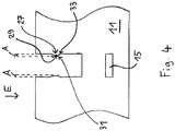
- FIG. 4 Another embodiment of the invention is in Fig. 4 shown.
- a detent 27 is provided, but no groove in the side wall 17 of the groove 13 is formed.
- the shoulder 31 runs here rather in a rounding 33.
- the distance A by which the latching nose 27 protrudes from the side wall 17, highlighted by dashed lines.
- the latch Compared to a purely frictional nesting of the CFC component elements 11, the latch not only allows greater stability, but also a simplified assembly.
Landscapes
- Engineering & Computer Science (AREA)
- Chemical & Material Sciences (AREA)
- Mechanical Engineering (AREA)
- General Engineering & Computer Science (AREA)
- Crystallography & Structural Chemistry (AREA)
- Thermal Sciences (AREA)
- Physics & Mathematics (AREA)
- Materials Engineering (AREA)
- Metallurgy (AREA)
- Organic Chemistry (AREA)
- Jigs For Machine Tools (AREA)
- Furnace Charging Or Discharging (AREA)
- Connection Of Plates (AREA)
- Powder Metallurgy (AREA)
Priority Applications (2)
| Application Number | Priority Date | Filing Date | Title |
|---|---|---|---|
| SI201330527A SI2906891T1 (sl) | 2012-10-10 | 2013-10-09 | Nosilec za obdelovance |
| PL13779775T PL2906891T3 (pl) | 2012-10-10 | 2013-10-09 | Wspornik dla przedmiotu obrabianego |
Applications Claiming Priority (2)
| Application Number | Priority Date | Filing Date | Title |
|---|---|---|---|
| DE102012218491.0A DE102012218491A1 (de) | 2012-10-10 | 2012-10-10 | Werkstückträger |
| PCT/EP2013/071090 WO2014057002A1 (de) | 2012-10-10 | 2013-10-09 | Werkstückträger |
Publications (2)
| Publication Number | Publication Date |
|---|---|
| EP2906891A1 EP2906891A1 (de) | 2015-08-19 |
| EP2906891B1 true EP2906891B1 (de) | 2016-12-14 |
Family
ID=49448120
Family Applications (1)
| Application Number | Title | Priority Date | Filing Date |
|---|---|---|---|
| EP13779775.9A Not-in-force EP2906891B1 (de) | 2012-10-10 | 2013-10-09 | Werkstückträger |
Country Status (11)
| Country | Link |
|---|---|
| US (1) | US20150211799A1 (lt) |
| EP (1) | EP2906891B1 (lt) |
| DE (1) | DE102012218491A1 (lt) |
| DK (1) | DK2906891T3 (lt) |
| ES (1) | ES2617736T3 (lt) |
| HU (1) | HUE033202T2 (lt) |
| LT (1) | LT2906891T (lt) |
| PL (1) | PL2906891T3 (lt) |
| PT (1) | PT2906891T (lt) |
| SI (1) | SI2906891T1 (lt) |
| WO (1) | WO2014057002A1 (lt) |
Cited By (1)
| Publication number | Priority date | Publication date | Assignee | Title |
|---|---|---|---|---|
| DE102019203594A1 (de) * | 2019-03-15 | 2020-09-17 | Sgl Carbon Se | Chargiergestell |
Families Citing this family (2)
| Publication number | Priority date | Publication date | Assignee | Title |
|---|---|---|---|---|
| US20170321964A1 (en) * | 2016-05-03 | 2017-11-09 | Saint-Gobain Ceramics & Plastics, Inc. | High temperature ceramic support rack |
| DE102018101994B4 (de) * | 2018-01-30 | 2025-06-05 | Ald Vacuum Technologies Gmbh | Vorrichtung zur Abstützung metallischer Werkstücke und Verfahren zur thermochemischen Behandlung |
Family Cites Families (13)
| Publication number | Priority date | Publication date | Assignee | Title |
|---|---|---|---|---|
| US652126A (en) * | 1899-03-14 | 1900-06-19 | Elmer R Lionberger | Egg-case filler. |
| US1443283A (en) * | 1920-04-17 | 1923-01-23 | Russell Company | Box cell case |
| DE8119990U1 (de) * | 1981-07-09 | 1981-12-24 | Friedrich, Uwe W., 4444 Bad Bentheim | Zusammenklappbarer Transportkasten |
| DE9404102U1 (de) * | 1994-03-11 | 1995-07-13 | Pies, Gerrit, 42699 Solingen | Verbindung eines Profilstabs mit einer daran zu befestigenden Profilleiste |
| DE29512569U1 (de) | 1995-08-04 | 1995-11-30 | Schunk Kohlenstofftechnik GmbH, 35452 Heuchelheim | Träger für Härtegut |
| DE19651408C2 (de) * | 1996-12-11 | 2001-04-19 | Fraunhofer Ges Forschung | Werkstückträger zum Wärmebehandeln von Werkstücken und Verwendung des Werkstückträgers |
| JP2000169910A (ja) * | 1998-12-02 | 2000-06-20 | Akio Shinba | 熱処理用治具 |
| CA2409061A1 (en) * | 2002-10-21 | 2004-04-21 | Corrugated Partitions Inc. | Carton divider |
| DE502004004737D1 (de) * | 2003-06-13 | 2007-10-04 | Schunk Kohlenstofftechnik Gmbh | Träger für Bauteile |
| DE20319600U1 (de) * | 2003-12-17 | 2004-03-18 | Sgl Carbon Ag | Werkstückträger aus faserverstärkter Keramik zum Wärmebehandeln von Werkstücken |
| DE102004017566A1 (de) * | 2004-04-07 | 2005-11-03 | Fraunhofer-Gesellschaft zur Förderung der angewandten Forschung e.V. | Werkstückträger zum Wärmebehandeln von Werkstücken |
| DE102009037293B4 (de) * | 2009-08-14 | 2013-05-23 | Gtd Graphit Technologie Gmbh | Verbesserter Werkstückträger |
| DE202010015436U1 (de) * | 2010-11-16 | 2011-01-27 | Sgl Carbon Se | Verriegelungselement, CFC-Bauteil und Halterungseinrichtung |
-
2012
- 2012-10-10 DE DE102012218491.0A patent/DE102012218491A1/de not_active Ceased
-
2013
- 2013-10-09 WO PCT/EP2013/071090 patent/WO2014057002A1/de not_active Ceased
- 2013-10-09 LT LTEP13779775.9T patent/LT2906891T/lt unknown
- 2013-10-09 SI SI201330527A patent/SI2906891T1/sl unknown
- 2013-10-09 EP EP13779775.9A patent/EP2906891B1/de not_active Not-in-force
- 2013-10-09 HU HUE13779775A patent/HUE033202T2/en unknown
- 2013-10-09 DK DK13779775.9T patent/DK2906891T3/en active
- 2013-10-09 ES ES13779775.9T patent/ES2617736T3/es active Active
- 2013-10-09 PT PT137797759T patent/PT2906891T/pt unknown
- 2013-10-09 PL PL13779775T patent/PL2906891T3/pl unknown
-
2015
- 2015-04-10 US US14/683,353 patent/US20150211799A1/en not_active Abandoned
Cited By (1)
| Publication number | Priority date | Publication date | Assignee | Title |
|---|---|---|---|---|
| DE102019203594A1 (de) * | 2019-03-15 | 2020-09-17 | Sgl Carbon Se | Chargiergestell |
Also Published As
| Publication number | Publication date |
|---|---|
| ES2617736T3 (es) | 2017-06-19 |
| PT2906891T (pt) | 2017-03-10 |
| SI2906891T1 (sl) | 2017-06-30 |
| EP2906891A1 (de) | 2015-08-19 |
| LT2906891T (lt) | 2017-05-25 |
| DE102012218491A1 (de) | 2014-04-10 |
| US20150211799A1 (en) | 2015-07-30 |
| WO2014057002A1 (de) | 2014-04-17 |
| PL2906891T3 (pl) | 2017-08-31 |
| HUE033202T2 (en) | 2017-11-28 |
| DK2906891T3 (en) | 2017-03-13 |
Similar Documents
| Publication | Publication Date | Title |
|---|---|---|
| EP3718176B1 (de) | Ver- und entriegelbarer steckverbinder | |
| EP2810829B1 (de) | Befestigungsclip | |
| DE19710489A1 (de) | Faltbares Schutzelement für Leitungen | |
| DE102007018254A1 (de) | Vorrichtung zum Befestigen von Ladegut in einem Transportmittel | |
| DE102016215037A1 (de) | Federvorrichtung und Verbindungsvorrichtung | |
| EP2677184B1 (de) | Segment eines wälzlagerkäfigs | |
| EP2906891B1 (de) | Werkstückträger | |
| DE202015100360U1 (de) | Kabelhalter und Kabelhaltersystem | |
| DE202008006934U1 (de) | Gehäuse für Lichtwellenleiter-Ferrule | |
| DE102012101117A1 (de) | Stangenschloss mit zusätzlicher Stangenstabilisierung | |
| DE112012003007T5 (de) | Verbinder | |
| EP4405606B1 (de) | Steckverbinder mit vormontagesicherung | |
| DE102015004158A1 (de) | Rastverbindungsvorrichtung zur lösbaren Befestigung eines Verkleidungsteils in einem Fahrzeuginnenraum | |
| EP2663708B1 (de) | Laufrollenträger für eine schiebetür | |
| EP3161331B1 (de) | Verbindungsanordnung | |
| DE102010026100A1 (de) | Schnellkupplung für Fluidleitungen | |
| DE102011006030B4 (de) | Segment eines Wälzlagerkäfigs | |
| DE112019004011T5 (de) | Montagesystem für ein Kastenprofil | |
| EP1587195B1 (de) | Kabelkanalsystem | |
| DE102016201263A1 (de) | Befestigungssystem | |
| EP3921554A1 (de) | Gleitelement | |
| DE102005024061A1 (de) | Zerstörungsfrei wiederlösbare Befestigungsmethode aus Kraft-, Formschluss | |
| DE102010042629A1 (de) | Halteelement eines Beschlagteils eines Treibstangenbeschlages | |
| EP2754762A1 (de) | Entwässerungs- und/oder Flüssigkeitsspeichervorrichtung zum Einbau ins Erdreich | |
| DE102008007135A1 (de) | Befestigungselement |
Legal Events
| Date | Code | Title | Description |
|---|---|---|---|
| PUAI | Public reference made under article 153(3) epc to a published international application that has entered the european phase |
Free format text: ORIGINAL CODE: 0009012 |
|
| 17P | Request for examination filed |
Effective date: 20150511 |
|
| AK | Designated contracting states |
Kind code of ref document: A1 Designated state(s): AL AT BE BG CH CY CZ DE DK EE ES FI FR GB GR HR HU IE IS IT LI LT LU LV MC MK MT NL NO PL PT RO RS SE SI SK SM TR |
|
| AX | Request for extension of the european patent |
Extension state: BA ME |
|
| DAX | Request for extension of the european patent (deleted) | ||
| GRAP | Despatch of communication of intention to grant a patent |
Free format text: ORIGINAL CODE: EPIDOSNIGR1 |
|
| INTG | Intention to grant announced |
Effective date: 20160623 |
|
| INTG | Intention to grant announced |
Effective date: 20160627 |
|
| GRAS | Grant fee paid |
Free format text: ORIGINAL CODE: EPIDOSNIGR3 |
|
| GRAA | (expected) grant |
Free format text: ORIGINAL CODE: 0009210 |
|
| AK | Designated contracting states |
Kind code of ref document: B1 Designated state(s): AL AT BE BG CH CY CZ DE DK EE ES FI FR GB GR HR HU IE IS IT LI LT LU LV MC MK MT NL NO PL PT RO RS SE SI SK SM TR |
|
| REG | Reference to a national code |
Ref country code: GB Ref legal event code: FG4D Free format text: NOT ENGLISH |
|
| REG | Reference to a national code |
Ref country code: CH Ref legal event code: EP |
|
| REG | Reference to a national code |
Ref country code: IE Ref legal event code: FG4D Free format text: LANGUAGE OF EP DOCUMENT: GERMAN |
|
| REG | Reference to a national code |
Ref country code: AT Ref legal event code: REF Ref document number: 853973 Country of ref document: AT Kind code of ref document: T Effective date: 20170115 |
|
| REG | Reference to a national code |
Ref country code: DE Ref legal event code: R096 Ref document number: 502013005770 Country of ref document: DE |
|
| PG25 | Lapsed in a contracting state [announced via postgrant information from national office to epo] |
Ref country code: LV Free format text: LAPSE BECAUSE OF FAILURE TO SUBMIT A TRANSLATION OF THE DESCRIPTION OR TO PAY THE FEE WITHIN THE PRESCRIBED TIME-LIMIT Effective date: 20161214 |
|
| REG | Reference to a national code |
Ref country code: PT Ref legal event code: SC4A Ref document number: 2906891 Country of ref document: PT Date of ref document: 20170310 Kind code of ref document: T Free format text: AVAILABILITY OF NATIONAL TRANSLATION Effective date: 20170303 |
|
| REG | Reference to a national code |
Ref country code: DK Ref legal event code: T3 Effective date: 20170309 |
|
| REG | Reference to a national code |
Ref country code: SE Ref legal event code: TRGR |
|
| REG | Reference to a national code |
Ref country code: NL Ref legal event code: FP |
|
| REG | Reference to a national code |
Ref country code: EE Ref legal event code: FG4A Ref document number: E013405 Country of ref document: EE Effective date: 20170303 |
|
| REG | Reference to a national code |
Ref country code: NO Ref legal event code: T2 Effective date: 20161214 |
|
| PG25 | Lapsed in a contracting state [announced via postgrant information from national office to epo] |
Ref country code: GR Free format text: LAPSE BECAUSE OF FAILURE TO SUBMIT A TRANSLATION OF THE DESCRIPTION OR TO PAY THE FEE WITHIN THE PRESCRIBED TIME-LIMIT Effective date: 20170315 |
|
| PG25 | Lapsed in a contracting state [announced via postgrant information from national office to epo] |
Ref country code: RS Free format text: LAPSE BECAUSE OF FAILURE TO SUBMIT A TRANSLATION OF THE DESCRIPTION OR TO PAY THE FEE WITHIN THE PRESCRIBED TIME-LIMIT Effective date: 20161214 Ref country code: HR Free format text: LAPSE BECAUSE OF FAILURE TO SUBMIT A TRANSLATION OF THE DESCRIPTION OR TO PAY THE FEE WITHIN THE PRESCRIBED TIME-LIMIT Effective date: 20161214 |
|
| REG | Reference to a national code |
Ref country code: ES Ref legal event code: FG2A Ref document number: 2617736 Country of ref document: ES Kind code of ref document: T3 Effective date: 20170619 |
|
| PG25 | Lapsed in a contracting state [announced via postgrant information from national office to epo] |
Ref country code: RO Free format text: LAPSE BECAUSE OF FAILURE TO SUBMIT A TRANSLATION OF THE DESCRIPTION OR TO PAY THE FEE WITHIN THE PRESCRIBED TIME-LIMIT Effective date: 20161214 |
|
| PG25 | Lapsed in a contracting state [announced via postgrant information from national office to epo] |
Ref country code: SM Free format text: LAPSE BECAUSE OF FAILURE TO SUBMIT A TRANSLATION OF THE DESCRIPTION OR TO PAY THE FEE WITHIN THE PRESCRIBED TIME-LIMIT Effective date: 20161214 Ref country code: BG Free format text: LAPSE BECAUSE OF FAILURE TO SUBMIT A TRANSLATION OF THE DESCRIPTION OR TO PAY THE FEE WITHIN THE PRESCRIBED TIME-LIMIT Effective date: 20170314 |
|
| REG | Reference to a national code |
Ref country code: DE Ref legal event code: R097 Ref document number: 502013005770 Country of ref document: DE |
|
| PLBE | No opposition filed within time limit |
Free format text: ORIGINAL CODE: 0009261 |
|
| STAA | Information on the status of an ep patent application or granted ep patent |
Free format text: STATUS: NO OPPOSITION FILED WITHIN TIME LIMIT |
|
| REG | Reference to a national code |
Ref country code: FR Ref legal event code: PLFP Year of fee payment: 5 |
|
| 26N | No opposition filed |
Effective date: 20170915 |
|
| REG | Reference to a national code |
Ref country code: HU Ref legal event code: AG4A Ref document number: E033202 Country of ref document: HU |
|
| PG25 | Lapsed in a contracting state [announced via postgrant information from national office to epo] |
Ref country code: MC Free format text: LAPSE BECAUSE OF FAILURE TO SUBMIT A TRANSLATION OF THE DESCRIPTION OR TO PAY THE FEE WITHIN THE PRESCRIBED TIME-LIMIT Effective date: 20161214 |
|
| PG25 | Lapsed in a contracting state [announced via postgrant information from national office to epo] |
Ref country code: LU Free format text: LAPSE BECAUSE OF NON-PAYMENT OF DUE FEES Effective date: 20171009 |
|
| PG25 | Lapsed in a contracting state [announced via postgrant information from national office to epo] |
Ref country code: MT Free format text: LAPSE BECAUSE OF FAILURE TO SUBMIT A TRANSLATION OF THE DESCRIPTION OR TO PAY THE FEE WITHIN THE PRESCRIBED TIME-LIMIT Effective date: 20161214 |
|
| REG | Reference to a national code |
Ref country code: FR Ref legal event code: PLFP Year of fee payment: 6 |
|
| PG25 | Lapsed in a contracting state [announced via postgrant information from national office to epo] |
Ref country code: CY Free format text: LAPSE BECAUSE OF FAILURE TO SUBMIT A TRANSLATION OF THE DESCRIPTION OR TO PAY THE FEE WITHIN THE PRESCRIBED TIME-LIMIT Effective date: 20161214 |
|
| PGFP | Annual fee paid to national office [announced via postgrant information from national office to epo] |
Ref country code: CZ Payment date: 20190927 Year of fee payment: 7 Ref country code: LT Payment date: 20190927 Year of fee payment: 7 |
|
| PG25 | Lapsed in a contracting state [announced via postgrant information from national office to epo] |
Ref country code: MK Free format text: LAPSE BECAUSE OF FAILURE TO SUBMIT A TRANSLATION OF THE DESCRIPTION OR TO PAY THE FEE WITHIN THE PRESCRIBED TIME-LIMIT Effective date: 20161214 |
|
| PGFP | Annual fee paid to national office [announced via postgrant information from national office to epo] |
Ref country code: IE Payment date: 20191021 Year of fee payment: 7 Ref country code: NO Payment date: 20191022 Year of fee payment: 7 Ref country code: NL Payment date: 20191022 Year of fee payment: 7 Ref country code: PT Payment date: 20191003 Year of fee payment: 7 Ref country code: HU Payment date: 20190925 Year of fee payment: 7 Ref country code: SE Payment date: 20191023 Year of fee payment: 7 Ref country code: FI Payment date: 20191022 Year of fee payment: 7 |
|
| PGFP | Annual fee paid to national office [announced via postgrant information from national office to epo] |
Ref country code: SI Payment date: 20190927 Year of fee payment: 7 Ref country code: EE Payment date: 20191021 Year of fee payment: 7 Ref country code: LV Payment date: 20191024 Year of fee payment: 7 Ref country code: IS Payment date: 20191017 Year of fee payment: 7 Ref country code: DK Payment date: 20191022 Year of fee payment: 7 Ref country code: BE Payment date: 20191022 Year of fee payment: 7 Ref country code: PL Payment date: 20191001 Year of fee payment: 7 |
|
| PG25 | Lapsed in a contracting state [announced via postgrant information from national office to epo] |
Ref country code: TR Free format text: LAPSE BECAUSE OF FAILURE TO SUBMIT A TRANSLATION OF THE DESCRIPTION OR TO PAY THE FEE WITHIN THE PRESCRIBED TIME-LIMIT Effective date: 20161214 |
|
| PGFP | Annual fee paid to national office [announced via postgrant information from national office to epo] |
Ref country code: AT Payment date: 20191018 Year of fee payment: 7 Ref country code: CH Payment date: 20191023 Year of fee payment: 7 |
|
| PG25 | Lapsed in a contracting state [announced via postgrant information from national office to epo] |
Ref country code: AL Free format text: LAPSE BECAUSE OF FAILURE TO SUBMIT A TRANSLATION OF THE DESCRIPTION OR TO PAY THE FEE WITHIN THE PRESCRIBED TIME-LIMIT Effective date: 20161214 |
|
| PG25 | Lapsed in a contracting state [announced via postgrant information from national office to epo] |
Ref country code: CZ Free format text: LAPSE BECAUSE OF NON-PAYMENT OF DUE FEES Effective date: 20201009 |
|
| REG | Reference to a national code |
Ref country code: EE Ref legal event code: MM4A Ref document number: E013405 Country of ref document: EE Effective date: 20201031 |
|
| REG | Reference to a national code |
Ref country code: NO Ref legal event code: MMEP Ref country code: DK Ref legal event code: EBP Effective date: 20201031 |
|
| REG | Reference to a national code |
Ref country code: CH Ref legal event code: PL Ref country code: FI Ref legal event code: MAE |
|
| REG | Reference to a national code |
Ref country code: SE Ref legal event code: EUG |
|
| REG | Reference to a national code |
Ref country code: NL Ref legal event code: MM Effective date: 20201101 |
|
| REG | Reference to a national code |
Ref country code: AT Ref legal event code: MM01 Ref document number: 853973 Country of ref document: AT Kind code of ref document: T Effective date: 20201009 |
|
| REG | Reference to a national code |
Ref country code: BE Ref legal event code: MM Effective date: 20201031 |
|
| PG25 | Lapsed in a contracting state [announced via postgrant information from national office to epo] |
Ref country code: NL Free format text: LAPSE BECAUSE OF NON-PAYMENT OF DUE FEES Effective date: 20201101 Ref country code: NO Free format text: LAPSE BECAUSE OF NON-PAYMENT OF DUE FEES Effective date: 20201031 Ref country code: EE Free format text: LAPSE BECAUSE OF NON-PAYMENT OF DUE FEES Effective date: 20201031 Ref country code: PT Free format text: LAPSE BECAUSE OF NON-PAYMENT OF DUE FEES Effective date: 20210409 Ref country code: FI Free format text: LAPSE BECAUSE OF NON-PAYMENT OF DUE FEES Effective date: 20201009 |
|
| REG | Reference to a national code |
Ref country code: LT Ref legal event code: MM4D Effective date: 20201009 |
|
| PG25 | Lapsed in a contracting state [announced via postgrant information from national office to epo] |
Ref country code: LV Free format text: LAPSE BECAUSE OF NON-PAYMENT OF DUE FEES Effective date: 20201009 Ref country code: BE Free format text: LAPSE BECAUSE OF NON-PAYMENT OF DUE FEES Effective date: 20201031 Ref country code: AT Free format text: LAPSE BECAUSE OF NON-PAYMENT OF DUE FEES Effective date: 20201009 Ref country code: CH Free format text: LAPSE BECAUSE OF NON-PAYMENT OF DUE FEES Effective date: 20201031 Ref country code: SE Free format text: LAPSE BECAUSE OF NON-PAYMENT OF DUE FEES Effective date: 20201010 Ref country code: SI Free format text: LAPSE BECAUSE OF NON-PAYMENT OF DUE FEES Effective date: 20201010 Ref country code: HU Free format text: LAPSE BECAUSE OF NON-PAYMENT OF DUE FEES Effective date: 20201010 Ref country code: LI Free format text: LAPSE BECAUSE OF NON-PAYMENT OF DUE FEES Effective date: 20201031 |
|
| REG | Reference to a national code |
Ref country code: SI Ref legal event code: KO00 Effective date: 20210811 |
|
| PG25 | Lapsed in a contracting state [announced via postgrant information from national office to epo] |
Ref country code: LT Free format text: LAPSE BECAUSE OF NON-PAYMENT OF DUE FEES Effective date: 20201009 Ref country code: IE Free format text: LAPSE BECAUSE OF NON-PAYMENT OF DUE FEES Effective date: 20201009 |
|
| PG25 | Lapsed in a contracting state [announced via postgrant information from national office to epo] |
Ref country code: DK Free format text: LAPSE BECAUSE OF NON-PAYMENT OF DUE FEES Effective date: 20201031 |
|
| PG25 | Lapsed in a contracting state [announced via postgrant information from national office to epo] |
Ref country code: PL Free format text: LAPSE BECAUSE OF NON-PAYMENT OF DUE FEES Effective date: 20201009 |
|
| PGFP | Annual fee paid to national office [announced via postgrant information from national office to epo] |
Ref country code: SK Payment date: 20231002 Year of fee payment: 11 |
|
| PGFP | Annual fee paid to national office [announced via postgrant information from national office to epo] |
Ref country code: GB Payment date: 20231025 Year of fee payment: 11 |
|
| PGFP | Annual fee paid to national office [announced via postgrant information from national office to epo] |
Ref country code: ES Payment date: 20231117 Year of fee payment: 11 |
|
| PGFP | Annual fee paid to national office [announced via postgrant information from national office to epo] |
Ref country code: IT Payment date: 20231031 Year of fee payment: 11 Ref country code: FR Payment date: 20231023 Year of fee payment: 11 Ref country code: DE Payment date: 20231018 Year of fee payment: 11 |
|
| P01 | Opt-out of the competence of the unified patent court (upc) registered |
Free format text: CASE NUMBER: APP_37195/2024 Effective date: 20240621 |
|
| REG | Reference to a national code |
Ref country code: DE Ref legal event code: R119 Ref document number: 502013005770 Country of ref document: DE |
|
| REG | Reference to a national code |
Ref country code: SK Ref legal event code: MM4A Ref document number: E 23576 Country of ref document: SK Effective date: 20241009 |
|
| GBPC | Gb: european patent ceased through non-payment of renewal fee |
Effective date: 20241009 |
|
| PG25 | Lapsed in a contracting state [announced via postgrant information from national office to epo] |
Ref country code: DE Free format text: LAPSE BECAUSE OF NON-PAYMENT OF DUE FEES Effective date: 20250501 |
|
| PG25 | Lapsed in a contracting state [announced via postgrant information from national office to epo] |
Ref country code: GB Free format text: LAPSE BECAUSE OF NON-PAYMENT OF DUE FEES Effective date: 20241009 |
|
| PG25 | Lapsed in a contracting state [announced via postgrant information from national office to epo] |
Ref country code: FR Free format text: LAPSE BECAUSE OF NON-PAYMENT OF DUE FEES Effective date: 20241031 |
|
| PG25 | Lapsed in a contracting state [announced via postgrant information from national office to epo] |
Ref country code: SK Free format text: LAPSE BECAUSE OF NON-PAYMENT OF DUE FEES Effective date: 20241009 |
|
| PG25 | Lapsed in a contracting state [announced via postgrant information from national office to epo] |
Ref country code: IT Free format text: LAPSE BECAUSE OF NON-PAYMENT OF DUE FEES Effective date: 20241009 |
|
| PG25 | Lapsed in a contracting state [announced via postgrant information from national office to epo] |
Ref country code: IS Free format text: LAPSE BECAUSE OF NON-PAYMENT OF DUE FEES Effective date: 20210512 |
|
| REG | Reference to a national code |
Ref country code: ES Ref legal event code: FD2A Effective date: 20251128 |
|
| PG25 | Lapsed in a contracting state [announced via postgrant information from national office to epo] |
Ref country code: ES Free format text: LAPSE BECAUSE OF NON-PAYMENT OF DUE FEES Effective date: 20241010 |