EP2906891B1 - Workpiece support - Google Patents
Workpiece support Download PDFInfo
- Publication number
- EP2906891B1 EP2906891B1 EP13779775.9A EP13779775A EP2906891B1 EP 2906891 B1 EP2906891 B1 EP 2906891B1 EP 13779775 A EP13779775 A EP 13779775A EP 2906891 B1 EP2906891 B1 EP 2906891B1
- Authority
- EP
- European Patent Office
- Prior art keywords
- cfc
- latching
- workpiece support
- support according
- latched
- Prior art date
- Legal status (The legal status is an assumption and is not a legal conclusion. Google has not performed a legal analysis and makes no representation as to the accuracy of the status listed.)
- Not-in-force
Links
Images


Classifications
-
- F—MECHANICAL ENGINEERING; LIGHTING; HEATING; WEAPONS; BLASTING
- F27—FURNACES; KILNS; OVENS; RETORTS
- F27D—DETAILS OR ACCESSORIES OF FURNACES, KILNS, OVENS OR RETORTS, IN SO FAR AS THEY ARE OF KINDS OCCURRING IN MORE THAN ONE KIND OF FURNACE
- F27D5/00—Supports, screens or the like for the charge within the furnace
- F27D5/0006—Composite supporting structures
-
- C—CHEMISTRY; METALLURGY
- C21—METALLURGY OF IRON
- C21D—MODIFYING THE PHYSICAL STRUCTURE OF FERROUS METALS; GENERAL DEVICES FOR HEAT TREATMENT OF FERROUS OR NON-FERROUS METALS OR ALLOYS; MAKING METAL MALLEABLE, e.g. BY DECARBURISATION OR TEMPERING
- C21D9/00—Heat treatment, e.g. annealing, hardening, quenching or tempering, adapted for particular articles; Furnaces therefor
- C21D9/0006—Details, accessories not peculiar to any of the following furnaces
- C21D9/0025—Supports; Baskets; Containers; Covers
Definitions
- the present invention relates to a workpiece carrier comprising at least two component elements, which are each composed of a carbon fiber reinforced carbon (CFC).
- CFC carbon fiber reinforced carbon
- CFC workpiece carriers are used to support or hold workpieces in high temperature environments.
- charging racks are used as a carrier, wherein the heat treatment to be subjected to workpieces are placed on a support surface of the charging frame in the simplest case.
- workpiece carriers made of CFC are characterized in particular by increased temperature resistance and better dimensional stability.
- the assembly of a workpiece carrier of a plurality of component elements is advantageous in terms of manufacturing costs and flexibility. In particular, this makes it possible to build complex frames, which are tuned to the respective workpiece type and quantity.
- the individual component elements can be plugged together, for example by means of frictional connection elements.
- a workpiece carrier for hardened material which is composed of four frame-like assembled CFC strips is, for example, in DE 295 12 569 U1 disclosed.
- At least two of the at least two CFC component elements are locked together.
- a latch engage at least two corresponding locking teeth form fit into each other and hold the two CFC component elements in a defined detent position, but under force overcoming the positive connection is possible in at least one direction. That is, when mating and possibly when pulling apart the component elements mentioned gear elements can slide past each other.
- a snap connection or click connection reaching the detent position is often audible and / or tactile perceptible (“clicking" or "snapping").
- the two CFC components are therefore not only plugged together and thereby frictionally connected, but there is also a positive connection due to the latching, which increases the stability of the overall component and prevents unwanted loosening or loosening of the individual components.
- An elaborate gluing is not required here. Due to the increase in the load-bearing capacity of the connection caused by the positive connection, material can be saved in the design of the component elements, as a result of which the production costs decrease.
- the latching of the at least two CFC component elements can preferably be achieved by overcoming a latching resistor.
- the workpiece carrier can then be easily disassembled if necessary.
- the force to be exerted on one of the two CFC component elements to overcome the detent resistance is at least 10 N.
- An adapted detent resistance on the one hand ensures sufficiently high security against unintentional release of the detent connection and on the other hand facilitates easy assembly and disassembly of the workpiece carrier , If a subsequent dismantling of the workpiece carrier is not considered, the detent resistance can also so be interpreted large that a non-destructive release of the locking is practically impossible.
- the workpiece carrier can also comprise at least three CFC component elements, wherein each of the at least three CFC component elements is latched with at least one further of the at least three CFC component elements.
- a workpiece carrier may comprise two CFC component elements designed as longitudinal members, which are arranged parallel to one another and overlapped by at least one CFC component element designed as a cross member, the cross member being latched at each end to one of the longitudinal members. In this way, in particular the construction of a rust- or lattice-like workpiece carrier is possible, which is suitable for supporting a plurality of different workpieces.
- a bearing surface for a workpiece can be formed on at least one of the at least two CFC component elements and preferably on each of the at least two CFC component elements.
- special fixing elements such as recesses or stirrups, to be provided on the CFC component elements that overlap the workpiece to be held.
- a locking projection may be provided on at least one of the at least two CFC component elements latched to each other, which latching projection is provided in a CFC component element locked to another of the at least two mutually latched components Locking engagement engages.
- the latching protrusion may be any area of material that protrudes from a base surface of the CFC component element, such as a flat wall. Depending on the application, such a locking projection may be tooth-shaped, hump-like or nose-shaped.
- the latching projection is configured in the manner of a ramp in order to provide a ramp for easier latching.
- the latching projection could be designed as a separate component element. However, it is preferred if the latching projection is formed directly on the associated CFC component element.
- the latching projection by a distance between 0.05 mm and 1.5 mm, preferably between 0.1 mm and 0.7 mm and particularly preferably between 0.2 mm and 0.4 mm relative to the base surface of associated CFC component element protrudes.
- Such distances have proved to be particularly favorable in that on the one hand a secure locking connection is ensured and on the other hand, a slight engagement or clicking one CFC component element in the other CFC component element is possible.
- both a latching projection and a latching receptacle are provided on each of the at least two mutually latched CFC component elements, the latching projections and the latching receptacles of two mutually latched CFC component elements being mutually engaged.
- the at least two CFC component elements can be plugged together for latching along an insertion direction, wherein the latching projection and the latching receptacle of each of the at least two CFC component elements are arranged one behind the other with respect to the insertion direction.
- the latching projection of one CFC component element thus automatically enters the latching receptacle of the other CFC component element and vice versa, so that a particularly simple latching is possible.
- At least one of the at least two interlocked CFC component elements may have a groove for receiving a male portion of the respective other CFC component element, wherein the latching projection projects from a side wall of the groove.
- the male portion may be any portion of the respective CFC component member whose width is matched to the width of the groove.
- the groove then serves as a guide for the CFC component element to be inserted and on the other hand provides the locking projection serving for latching.
- the at least two mutually locked CFC component elements are plate-like and each have at least one groove, wherein the grooves mutually engage.
- Such CFC component elements are relatively easy to produce and are particularly suitable for the construction of grid-like charging racks.
- the groove may in particular have a rectangular cross-section. This allows a particularly simple production.
- a further embodiment of the invention provides that at least one of the at least two interconnected CFC component elements, and preferably each of the at least two interconnected CFC component elements, has at least three spaced-apart grooves for receiving an insertion portion of another CFC component element.
- the grooves may have a rounded cross section, wherein the radius of curvature of the rounding is at least 0.1 mm and preferably at least 0.3 mm.
- At least one side wall of the groove may be formed a ramp-like locking projection and an adjacent thereto groove.
- the groove facilitates the snapping or clicking the locking projection into the associated locking receptacle.
- the at least two CFC component elements are each composed of a carbon fiber-reinforced carbon which comprises carbonized and / or graphitized polyacrylonitrile fibers. With such fibers particularly good results were achieved.
- the at least two CFC component elements are each composed of a carbon reinforced with carbon fibers, carbon fibers and / or drawn fibers.
- the at least two CFC component elements are each composed of a carbon fiber reinforced carbon comprising carbon fibers having an average diameter of between 5 ⁇ m and 10 ⁇ m.
- a particularly favorable value has been found to be an average diameter of the carbon fibers of about 7 ⁇ m.
- the at least two CFC component elements are each composed of a carbon fiber-reinforced carbon which is at least 30% by volume, preferably at least 50% by volume and more preferably at least 70 vol .-% of carbon fibers.
- the at least two CFC component elements have a temperature resistance of at least 1,500 ° C., and preferably of at least 2,500 ° C.
- the workpiece carrier can be composed exclusively of, preferably identical, CFC component elements. This allows a particularly cost-effective production.
- the workpiece carrier has a size (BxLxH) of at least 50 mm ⁇ 50 mm ⁇ 10 mm, preferably of at least 100 mm ⁇ 100 mm ⁇ 10 mm and particularly preferably of at least 300 mm ⁇ 300 mm ⁇ 20 mm, for example of 1200 mm x 1,200 mm x 50 mm, on.
- Workpiece carrier of this Size are commonly used as charging racks when curing or sintering components.
- Another object of the present invention is the use of a previously described workpiece carrier as a charging rack in a high temperature environment.
- plate-shaped component member 11 is made entirely of a carbon fiber reinforced carbon (CFC) and is used to construct a workpiece carrier such as a Chargiergestells.
- CFC carbon fiber reinforced carbon
- the carbon fiber reinforced carbon comprises carbonized and / or graphitized polyacrylonitrile continuous filaments embedded in a matrix of carbon in a proportion of at least 80% by volume.
- the fibers have an average diameter of about 7 microns.
- the CFC component element 11 is configured in the form of an elongate strip and has a longitudinal axis L.
- Four grooves 13 of rectangular cross-section are formed along the longitudinal axis L spaced apart in the CFC component element 11.
- the width B of each groove corresponds to that in the Fig. 1 not apparent thickness of the plate-shaped CFC component element 11.
- the CFC component element 11 has four rectangular recesses 15, which are each adjacent to a groove 13 and whose width corresponds to the width B of the grooves 13.
- each groove 13 has two opposing side walls 17, wherein in each of the side walls 17 are two mutually parallel and transverse to the longitudinal axis L spaced apart grooves 19 are formed. Between the two grooves 19 of a side wall 17 is in each case a slightly rounded Rastbuckel 20, which protrudes relative to the surface of the side wall 17 by about 0.35 mm.
- the recesses 15 and the Rastbuckel 20 can each two according to the Fig. 1 designed CFC component elements 11 are locked together, as will be explained in more detail below.
- the two CFC component elements 11 to be joined are initially arranged in a fundamentally known manner such that their longitudinal axes L run at right angles to one another and an upper-side groove 13 of one CFC component element 11 opposes a lower-side groove 13 of the other CFC component element 11.
- the two CFC component elements 11 are then brought together along an insertion direction E pointing transversely to the two longitudinal axes L, wherein the grooves 13 mutually intermesh.
- the locking resistance can be adjusted relatively accurately to an application-related default value.
- three or more CFC component elements 11 can be easily frame or lattice-like workpiece carrier in the manner described, in which the narrow sides 23 of the CFC component elements 11 form respective bearing surfaces 25 for workpieces.
- Such workpiece carriers are particularly suitable as charging racks in hardening or sintering furnaces. The fact that the associated component elements 11 are made exclusively of CFC, a sufficient temperature resistance and dimensional stability is guaranteed.
- Assembling a workpiece carrier by latching the CFC component elements 11 is simple and requires no special knowledge. It can therefore also be performed by a respective end customer, while the manufacturer of the workpiece carrier provides only a set of CFC component elements 11 for individual mating as a kit.
- a particular advantage of the illustrated system is that there are no undercuts, which require the consideration of different plug-in directions and the maintenance of a particular order during assembly during assembly. There are also no gluing or separate fasteners such as pins or pins necessary because the stability of the CFC component assembly is ensured by the latches.
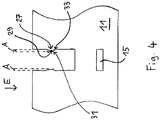
- Fig. 3 shows an alternative embodiment of a CFC component element 11 according to the invention, wherein instead of a Rastbuckels here a locking lug 27 is provided with a ramp portion 29 and a shoulder 31.
- the approach shoulder 31 is followed by a single groove 19.
- the ramp portion 29 of the locking lug 27 forms a ramp for the insertion portion 21 of the other CFC component element 11, thus facilitating the mating of the two CFC component elements 11.
- the shoulder 31 provides for this in comparison to the embodiment according to the Fig. 1 and 2 increased locking resistance.
- FIG. 4 Another embodiment of the invention is in Fig. 4 shown.
- a detent 27 is provided, but no groove in the side wall 17 of the groove 13 is formed.
- the shoulder 31 runs here rather in a rounding 33.
- the distance A by which the latching nose 27 protrudes from the side wall 17, highlighted by dashed lines.
- the latch Compared to a purely frictional nesting of the CFC component elements 11, the latch not only allows greater stability, but also a simplified assembly.
Landscapes
- Engineering & Computer Science (AREA)
- Chemical & Material Sciences (AREA)
- Mechanical Engineering (AREA)
- General Engineering & Computer Science (AREA)
- Crystallography & Structural Chemistry (AREA)
- Thermal Sciences (AREA)
- Physics & Mathematics (AREA)
- Materials Engineering (AREA)
- Metallurgy (AREA)
- Organic Chemistry (AREA)
- Jigs For Machine Tools (AREA)
- Furnace Charging Or Discharging (AREA)
- Powder Metallurgy (AREA)
- Connection Of Plates (AREA)
Description
Die vorliegende Erfindung betrifft einen Werkstückträger umfassend wenigstens zwei Bauteilelemente, welche jeweils aus einem carbonfaserverstärkten Kohlenstoff (CFC) zusammengesetzt sind.The present invention relates to a workpiece carrier comprising at least two component elements, which are each composed of a carbon fiber reinforced carbon (CFC).
Werkstückträger aus CFC werden zum Stützen oder Halten von Werkstücken in Hochtemperaturumgebungen benutzt. Beispielsweise werden beim Härten oder Sintern von Werkstücken in Industrieöfen sogenannte Chargiergestelle als Träger verwendet, wobei die der Wärmebehandlung zu unterziehenden Werkstücke im einfachsten Fall auf eine Auflagefläche des Chargiergestells aufgelegt werden. Gegenüber Werkstückträgern aus Stahl zeichnen sich Werkstückträger aus CFC insbesondere durch eine erhöhte Temperaturbeständigkeit und eine bessere Formstabilität aus.CFC workpiece carriers are used to support or hold workpieces in high temperature environments. For example, when curing or sintering of workpieces in industrial furnaces so-called charging racks are used as a carrier, wherein the heat treatment to be subjected to workpieces are placed on a support surface of the charging frame in the simplest case. Compared with workpiece carriers made of steel, workpiece carriers made of CFC are characterized in particular by increased temperature resistance and better dimensional stability.
Das Zusammensetzen eines Werkstückträgers aus mehreren Bauteilelementen ist hinsichtlich der Herstellungskosten sowie der Flexibilität vorteilhaft. Insbesondere ist es dadurch möglich, komplexe Gestelle aufzubauen, welche auf die jeweilige Werkstückart- und -menge abgestimmt sind. Die einzelnen Bauteilelemente können beispielsweise mittels reibschlüssiger Verbindungselemente zusammengesteckt werden. Ein Werkstückträger für Härtegut, welcher aus vier rahmenartig zusammengesteckten CFC-Leisten aufgebaut ist, ist beispielsweise in der
Bei solchen Werkstückträgern aus zusammengesteckten CFC-Bauteilelementen besteht jedoch das Problem, dass die betreffenden reibschlüssigen Verbindungselemente, wie Führungsrippen und -nuten, mit relativ hoher Genauigkeit gefertigt werden müssen, um eine unerwünscht lockere Verbindung einerseits und ein Verklemmen der Bauteilelemente beim Zusammenstecken andererseits zu verhindern. Dies ist mit einem hohen Herstellungsaufwand verbunden. Weiterhin kann es aufgrund der hohen Temperaturen und der starken Temperaturunterschiede während eines Härt- oder Sinterprozesses zu einem Lösen der reibschlüssigen Verbindung und in der Folge zu einer unerwünschten Verformung des gesamten Werkstückträgers kommen. Um ein solches unerwünschtes Lösen zweier verbundener Bauteilelemente zu verhindern, können diese miteinander verklebt werden, was jedoch wiederum mit einem erhöhten Herstellungsaufwand einhergeht.In such workpiece carriers made of assembled CFC component elements, however, there is the problem that the respective frictional connection elements, such as guide ribs and grooves, manufactured with relatively high accuracy must be to prevent an undesirable loose connection on the one hand and jamming of the component elements during mating on the other hand. This is associated with a high production cost. Furthermore, due to the high temperatures and the strong temperature differences during a curing or sintering process, the frictional connection can be released and, as a consequence, undesired deformation of the entire workpiece carrier. In order to prevent such unwanted loosening of two connected component elements, they can be glued together, which in turn, however, is accompanied by an increased production effort.
In der
Es ist daher eine Aufgabe der vorliegenden Erfindung, Werkstückträger der vorstehend genannten Art mit einfachen Mitteln derart weiterzubilden, dass ein unerwünschtes Lösen der einzelnen Bauteilelemente sicher verhindert wird.It is therefore an object of the present invention to further develop workpiece carriers of the aforementioned type with simple means in such a way that undesired release of the individual component elements is reliably prevented.
Die Lösung der Aufgabe erfolgt durch einen Werkstückträger mit den Merkmalen des Anspruchs 1.The object is achieved by a workpiece carrier with the features of claim 1.
Erfindungsgemäß sind wenigstens zwei der wenigstens zwei CFC-Bauteilelemente miteinander verrastet. Bei einer solchen Verrastung greifen wenigstens zwei entsprechende Rastverzahnungselemente formschlüssig ineinander und halten die beiden CFC-Bauteilelemente in einer definierten Raststellung fest, wobei jedoch unter Kraftaufwand ein Überwinden des Formschlusses zumindest in einer Richtung möglich ist. D.h. beim Zusammenstecken und gegebenenfalls beim Auseinanderziehen der Bauteilelemente können die erwähnten Verzahnungselemente aneinander vorbeigleiten. Bei einer solchen Rastverbindung bzw. Klickverbindung ist das Erreichen der Raststellung häufig akustisch und/oder taktil wahrnehmbar ("Einklicken" oder "Einschnappen").According to the invention, at least two of the at least two CFC component elements are locked together. In such a latch engage at least two corresponding locking teeth form fit into each other and hold the two CFC component elements in a defined detent position, but under force overcoming the positive connection is possible in at least one direction. That is, when mating and possibly when pulling apart the component elements mentioned gear elements can slide past each other. In such a snap connection or click connection reaching the detent position is often audible and / or tactile perceptible ("clicking" or "snapping").
Die beiden CFC-Bauteile sind also nicht nur zusammengesteckt und hierdurch reibschlüssig verbunden, sondern es besteht aufgrund der Verrastung auch eine formschlüssige Verbindung, welche die Stabilität des Gesamtbauteils erhöht und ein unerwünschtes Lockern oder Lösen der Einzelbauteile verhindert. Ein aufwändiges Verkleben ist hierbei nicht erforderlich. Aufgrund der durch den Formschluss bewirkten Erhöhung der Belastbarkeit der Verbindung kann bei der Auslegung der Bauteilelemente Material eingespart werden, wodurch die Herstellungskosten sinken.The two CFC components are therefore not only plugged together and thereby frictionally connected, but there is also a positive connection due to the latching, which increases the stability of the overall component and prevents unwanted loosening or loosening of the individual components. An elaborate gluing is not required here. Due to the increase in the load-bearing capacity of the connection caused by the positive connection, material can be saved in the design of the component elements, as a result of which the production costs decrease.
Feste formschlüssige Verbindungen in Form von Hinterschneidungen oder Verstiftungen erfordern häufig ein kompliziertes Zusammensetzen der Bauteilelemente aus verschiedenen Richtungen und in einer genau vorgegebenen Reihenfolge. Demgegenüber ist ein Verrasten zweier Bauteilelemente besonders schnell und einfach möglich. An eine Rastverbindung sind außerdem nur vergleichweise geringe Maßhaltigkeitsanforderungen zu stellen. Somit ist es insbesondere möglich, Bausätze für Werkstückträger anzubieten, mittels welchen Endkunden individuelle Werkstückträger in Abhängigkeit von der jeweiligen Anwendung durch einfaches einklickendes Zusammenstecken der Einzelteile herstellen können.Fixed positive connections in the form of undercuts or pinnacles often require a complicated assembly of the component elements from different directions and in a precisely predetermined order. In contrast, a locking two component elements is particularly fast and easy. At a locking connection only comparatively low Maßhaltigkeitsanforderungen are also to make. Thus, it is possible, in particular, to offer kits for workpiece carriers, by means of which end customers can produce individual workpiece carriers as a function of the respective application by simply clicking in the individual parts.
Vorzugsweise ist die Verrastung der wenigstens zwei CFC-Bauteilelemente unter Überwindung eines Rastwiderstands lösbar. Der Werkstückträger kann dann bei Bedarf leicht zerlegt werden.The latching of the at least two CFC component elements can preferably be achieved by overcoming a latching resistor. The workpiece carrier can then be easily disassembled if necessary.
Gemäß einer Ausführungsform der Erfindung beträgt die auf eines der zwei CFC-Bauteilelemente zur Überwindung des Rastwiderstands mindestens auszuübende Kraft wenigstens 10 N. Ein angepasster Rastwiderstand gewährleistet einerseits eine ausreichend hohe Sicherheit gegen ein unbeabsichtigtes Lösen der Rastverbindung und ermöglicht andererseits ein leichtes Zusammenbauen und Auseinanderbauen des Werkstückträgers. Sofern ein nachträgliches Zerlegen des Werkstückträgers nicht in Erwägung gezogen wird, kann der Rastwiderstand auch so groß ausgelegt werden, dass ein zerstörungsfreies Lösen der Verrastung praktisch nicht möglich ist.According to one embodiment of the invention, the force to be exerted on one of the two CFC component elements to overcome the detent resistance is at least 10 N. An adapted detent resistance on the one hand ensures sufficiently high security against unintentional release of the detent connection and on the other hand facilitates easy assembly and disassembly of the workpiece carrier , If a subsequent dismantling of the workpiece carrier is not considered, the detent resistance can also so be interpreted large that a non-destructive release of the locking is practically impossible.
Der Werkstückträger kann gemäß einer Ausgestaltung der Erfindung auch wenigstens drei CFC-Bauteilelemente umfassen, wobei jedes der wenigstens drei CFC-Bauteilelemente mit wenigstens einem weiteren der wenigstens drei CFC-Bauteilelemente verrastet ist. Dies ermöglicht den Aufbau vergleichsweise komplexer Werkstückträger, wobei die einzelnen Bauteilelemente durch die gegenseitige Verrastung sicher zusammengehalten werden. Beispielsweise kann ein Werkstückträger zwei als Längsträger ausgestaltete CFC-Bauteilelemente umfassen, die parallel zueinander angeordnet sind und durch wenigstens ein als Querträger ausgebildetes CFC-Bauteilelement übergriffen werden, wobei der Querträger an beiden Enden jeweils mit einem der Längsträger verrastet ist. Auf diese Weise ist insbesondere der Aufbau eines rost- oder gitterartigen Werkstückträgers möglich, welcher zum Stützen einer Vielzahl von unterschiedlichen Werkstücken geeignet ist.According to one embodiment of the invention, the workpiece carrier can also comprise at least three CFC component elements, wherein each of the at least three CFC component elements is latched with at least one further of the at least three CFC component elements. This allows the construction of comparatively complex workpiece carrier, wherein the individual component elements are securely held together by the mutual locking. For example, a workpiece carrier may comprise two CFC component elements designed as longitudinal members, which are arranged parallel to one another and overlapped by at least one CFC component element designed as a cross member, the cross member being latched at each end to one of the longitudinal members. In this way, in particular the construction of a rust- or lattice-like workpiece carrier is possible, which is suitable for supporting a plurality of different workpieces.
Um ein einfaches und zuverlässiges Halten von Werkstücken zu ermöglichen, kann an wenigstens einem der wenigstens zwei CFC-Bauteilelemente und bevorzugt an jedem der wenigstens zwei CFC-Bauteilelemente eine Auflagefläche für ein Werkstück ausgebildet sein. Sofern es die Anwendung erfordert, können jedoch auch spezielle, das zu haltende Werkstück übergreifende Fixierelemente wie Aussparungen oder Bügel an den CFC-Bauteilelementen vorgesehen sein. Ebenso kann es bei bestimmten Anwendungen vorteilhaft sein, separate Auflage- oder Halteelemente - beispielsweise aus Keramik - vorzusehen, die mit den CFC-Bauteilelementen verbunden sind.In order to enable a simple and reliable holding of workpieces, a bearing surface for a workpiece can be formed on at least one of the at least two CFC component elements and preferably on each of the at least two CFC component elements. However, if required by the application, it is also possible for special fixing elements, such as recesses or stirrups, to be provided on the CFC component elements that overlap the workpiece to be held. Likewise, in certain applications, it may be advantageous to provide separate support or support elements, for example of ceramic, which are connected to the CFC component elements.
An wenigstens einem der wenigstens zwei miteinander verrasteten CFC-Bauteilelemente kann ein Rastvorsprung vorgesehen sein, welcher in eine an einem anderen der wenigstens zwei miteinander verrasteten CFC-Bauteilelemente vorgesehene Rastaufnahme eingreift. Bei dem Rastvorsprung kann es sich um einen beliebigen Materialbereich handeln, der gegenüber einer Basisfläche des CFC-Bauteilelements, wie z.B. einer ebenen Wand, vorsteht. Je nach Anwendungsvorgabe kann ein solcher Rastvorsprung zahnartig, buckelartig oder nasenartig geformt sein. Bevorzugt ist der Rastvorsprung rampenartig ausgestaltet, um eine Auflaufschräge zum leichteren Herbeiführen der Verrastung bereitzustellen. Grundsätzlich könnte der Rastvorsprung als separates Bauteilelement ausgeführt sein. Bevorzugt ist es jedoch, wenn der Rastvorsprung direkt an das zugehörige CFC-Bauteilelement angeformt ist.A locking projection may be provided on at least one of the at least two CFC component elements latched to each other, which latching projection is provided in a CFC component element locked to another of the at least two mutually latched components Locking engagement engages. The latching protrusion may be any area of material that protrudes from a base surface of the CFC component element, such as a flat wall. Depending on the application, such a locking projection may be tooth-shaped, hump-like or nose-shaped. Preferably, the latching projection is configured in the manner of a ramp in order to provide a ramp for easier latching. In principle, the latching projection could be designed as a separate component element. However, it is preferred if the latching projection is formed directly on the associated CFC component element.
Es kann vorgesehen sein, dass der Rastvorsprung um einen Abstand zwischen 0,05 mm und 1,5 mm, bevorzugt zwischen 0,1 mm und 0,7 mm und besonders bevorzugt zwischen 0,2 mm und 0,4 mm gegenüber der Basisfläche des zugehörigen CFC-Bauteilelements vorsteht. Derartige Abstände haben sich dahingehend als besonders günstig erwiesen, dass einerseits eine sichere Rastverbindung gewährleistet ist und andererseits ein leichtes Einrasten oder Einklicken des einen CFC-Bauteilelements in das andere CFC-Bauteilelement möglich ist.It can be provided that the latching projection by a distance between 0.05 mm and 1.5 mm, preferably between 0.1 mm and 0.7 mm and particularly preferably between 0.2 mm and 0.4 mm relative to the base surface of associated CFC component element protrudes. Such distances have proved to be particularly favorable in that on the one hand a secure locking connection is ensured and on the other hand, a slight engagement or clicking one CFC component element in the other CFC component element is possible.
Gemäß der Erfindung ist an jedem der wenigstens zwei miteinander verrasteten CFC-Bauteilelemente sowohl ein Rastvorsprung als auch eine Rastaufnahme vorgesehen, wobei die Rastvorsprünge und die Rastaufnahmen jeweils zweier miteinander verrasteter CFC-Bauteilelemente wechselseitig in Eingriff stehen. Hierdurch wird die Konstruktion des Werkstückträgers vereinfacht. Insbesondere muss beim Zusammenbau nicht darauf geachtet werden, dass eine ausreichende Anzahl an CFC-Bauteilelementen mit Rastvorsprung sowie an CFC-Bauteilelementen mit Rastaufnahme zur Verfügung steht, da stets für jeden Rastvorsprung eine Rastaufnahme bereitsteht. Auf diese Weise ist der Aufbau unterschiedlicher Werkstückträger aus einem beschränkten Satz von Grundelementen im Sinne eines Baukastensystems möglich.According to the invention, both a latching projection and a latching receptacle are provided on each of the at least two mutually latched CFC component elements, the latching projections and the latching receptacles of two mutually latched CFC component elements being mutually engaged. As a result, the construction of the workpiece carrier is simplified. In particular, care must be taken during assembly not that a sufficient number of CFC component elements with locking projection and on CFC component elements with locking receptacle is available, as always a catch receptacle is available for each locking projection. In this way, the construction of different workpiece carriers from a limited set of basic elements in terms of a modular system is possible.
Ein weiterer Aspekt der Erfindung sieht vor, dass die wenigstens zwei CFC-Bauteilelemente zum Verrasten entlang einer Einsteckrichtung zusammensteckbar sind, wobei der Rastvorsprung und die Rastaufnahme jedes der wenigstens zwei CFC-Bauteilelemente bezüglich der Einsteckrichtung hintereinander angeordnet sind. Beim Zusammenführen der CFC-Bauteilelemente entlang der Einsteckrichtung gelangt somit der Rastvorsprung des einen CFC-Bauteilelements automatisch in die Rastaufnahme des anderen CFC-Bauteilelements und umgekehrt, sodass ein besonders einfaches Einrasten möglich ist.Another aspect of the invention provides that the at least two CFC component elements can be plugged together for latching along an insertion direction, wherein the latching projection and the latching receptacle of each of the at least two CFC component elements are arranged one behind the other with respect to the insertion direction. When the CFC component elements are brought together along the insertion direction, the latching projection of one CFC component element thus automatically enters the latching receptacle of the other CFC component element and vice versa, so that a particularly simple latching is possible.
Wenigstens eines der wenigstens zwei miteinander verrasteten CFC-Bauteilelemente kann eine Nut zum Aufnehmen eines Einsteckabschnitts des jeweils anderen CFC-Bauteilelements aufweisen, wobei der Rastvorsprung von einer Seitenwand der Nut absteht. Der Einsteckabschnitt kann ein beliebiger Bereich des betreffenden CFC-Bauteilelements sein, dessen Breite an die Breite der Nut angepasst ist. Die Nut dient dann einerseits als Führung für das einzusteckende CFC-Bauteilelement und stellt andererseits den zum Verrasten dienenden Rastvorsprung bereit.At least one of the at least two interlocked CFC component elements may have a groove for receiving a male portion of the respective other CFC component element, wherein the latching projection projects from a side wall of the groove. The male portion may be any portion of the respective CFC component member whose width is matched to the width of the groove. On the one hand, the groove then serves as a guide for the CFC component element to be inserted and on the other hand provides the locking projection serving for latching.
Es können auch von zwei einander gegenüberliegenden Seitenwänden der Nut jeweilige Rastvorsprünge abstehen. Dadurch kann die Stabilität der Rastverbindung erhöht werden.It can also protrude from two opposite side walls of the groove respective latching projections. As a result, the stability of the latching connection can be increased.
Gemäß einer konkreten Ausgestaltung der Erfindung sind die wenigstens zwei miteinander verrasteten CFC-Bauteilelemente plattenartig ausgebildet und weisen jeweils wenigstens eine Nut auf, wobei die Nuten wechselseitig ineinandergreifen. Solche CFC-Bauteilelemente sind relativ leicht herstellbar und eignen sich insbesondere zum Aufbau gitterartiger Chargiergestelle.According to a specific embodiment of the invention, the at least two mutually locked CFC component elements are plate-like and each have at least one groove, wherein the grooves mutually engage. Such CFC component elements are relatively easy to produce and are particularly suitable for the construction of grid-like charging racks.
Die Nut kann insbesondere einen rechteckigen Querschnitt aufweisen. Dies ermöglicht eine besonders einfache Herstellung.The groove may in particular have a rectangular cross-section. This allows a particularly simple production.
Eine weitere Ausführungsform der Erfindung sieht vor, dass wenigstens eines der wenigstens zwei miteinander verrasteten CFC-Bauteilelemente und vorzugsweise jedes der wenigstens zwei miteinander verrasteten CFC-Bauteilelemente wenigstens drei voneinander beabstandete Nuten zum Aufnehmen eines Einsteckabschnitts eines anderen CFC-Bauteilelements aufweist. Hierdurch kann die Flexibilität beim Aufbau eines anwendungsbezogenen Werkstückträgers weiter gesteigert werden.A further embodiment of the invention provides that at least one of the at least two interconnected CFC component elements, and preferably each of the at least two interconnected CFC component elements, has at least three spaced-apart grooves for receiving an insertion portion of another CFC component element. As a result, the flexibility in the construction of an application-related workpiece carrier can be further increased.
Es kann vorgesehen sein, dass in wenigstens einer Seitenwand der Nut zwei parallele und zueinander beabstandete Rillen ausgebildet sind, zwischen denen sich der, insbesondere plateau- oder buckelartige, Rastvorsprung erstreckt. Eine derartige Ausgestaltung des Rastvorsprungs hat sich hinsichtlich einer leichten Verrastbarkeit als vorteilhaft herausgestellt.It can be provided that in at least one side wall of the groove two parallel and mutually spaced grooves are formed, between which extends the, in particular plateau- or hump-like, locking projection. Such a configuration of the latching projection has been found to be advantageous in terms of easy latching.
Die Rillen können einen abgerundeten Querschnitt aufweisen, wobei der Krümmungsradius der Rundung wenigstens 0,1 mm und bevorzugt wenigstens 0,3 mm beträgt.The grooves may have a rounded cross section, wherein the radius of curvature of the rounding is at least 0.1 mm and preferably at least 0.3 mm.
Weiterhin kann in wenigstens einer Seitenwand der Nut ein rampenartiger Rastvorsprung und eine zu diesem benachbarte Rille ausgebildet sein. Die Rille erleichtert das Einrasten oder Einklicken des Rastvorsprungs in die zugehörige Rastaufnahme.Furthermore, in at least one side wall of the groove may be formed a ramp-like locking projection and an adjacent thereto groove. The groove facilitates the snapping or clicking the locking projection into the associated locking receptacle.
Vorzugsweise sind die wenigstens zwei CFC-Bauteilelemente jeweils aus einem carbonfaserverstärkten Kohlenstoff zusammengesetzt, welcher carbonisierte und/oder graphitierte Poylacrylnitrilfasern umfasst. Mit derartigen Fasern wurden besonders gute Ergebnisse erzielt.Preferably, the at least two CFC component elements are each composed of a carbon fiber-reinforced carbon which comprises carbonized and / or graphitized polyacrylonitrile fibers. With such fibers particularly good results were achieved.
Ferner ist es bevorzugt, dass die wenigstens zwei CFC-Bauteilelemente jeweils aus einem mit Carbonendlosfasern, Carbonschnittfasern und/oder streckgerissenen Fasern verstärkten Kohlenstoff zusammengesetzt sind.Furthermore, it is preferred that the at least two CFC component elements are each composed of a carbon reinforced with carbon fibers, carbon fibers and / or drawn fibers.
Hinsichtlich der Faserdicke ist es bevorzugt, dass die wenigstens zwei CFC-Bauteilelemente jeweils aus einem carbonfaserverstärkten Kohlenstoff zusammengesetzt sind, welcher Carbonfasern mit einem durchschnittlichen Durchmesser zwischen 5 µm und 10 µm umfasst. Als besonders günstiger Wert hat sich ein durchschnittlicher Durchmesser der Carbonfasern von etwa 7 µm erwiesen.With regard to the fiber thickness, it is preferable that the at least two CFC component elements are each composed of a carbon fiber reinforced carbon comprising carbon fibers having an average diameter of between 5 μm and 10 μm. A particularly favorable value has been found to be an average diameter of the carbon fibers of about 7 μm.
In Bezug auf den Faseranteil der CFC-Bauteilelemente hat es sich als vorteilhaft erwiesen, dass die wenigstens zwei CFC-Bauteilelemente jeweils aus einem carbonfaserverstärkten Kohlenstoff zusammengesetzt sind, der wenigstens 30 Vol.-%, bevorzugt wenigstens 50 Vol.-% und besonders bevorzugt wenigstens 70 Vol.-% an Carbonfasern umfasst.With regard to the fiber content of the CFC component elements, it has proved to be advantageous that the at least two CFC component elements are each composed of a carbon fiber-reinforced carbon which is at least 30% by volume, preferably at least 50% by volume and more preferably at least 70 vol .-% of carbon fibers.
Um einen sicheren Einsatz des Werkstückträgers beim Härten oder Sintern zu gewährleisten, ist es bevorzugt, dass die wenigstens zwei CFC-Bauteilelemente eine Temperaturbeständigkeit von wenigstens 1.500°C und bevorzugt von wenigstens 2.500°C aufweisen.In order to ensure a secure use of the workpiece carrier during curing or sintering, it is preferred that the at least two CFC component elements have a temperature resistance of at least 1,500 ° C., and preferably of at least 2,500 ° C.
Der Werkstückträger kann ausschließlich aus, vorzugsweise gleichartigen, CFC-Bauteilelementen zusammengesetzt sein. Dies ermöglicht eine besonders kostengünstige Herstellung.The workpiece carrier can be composed exclusively of, preferably identical, CFC component elements. This allows a particularly cost-effective production.
Vorzugsweise weist der Werkstückträger eine Größe (BxLxH) von wenigstens 50 mm x 50 mm x 10 mm, bevorzugt von wenigstens 100 mm x 100 mm x 10 mm und besonders bevorzugt von wenigstens 300 mm x 300 mm x 20 mm, wie beispielsweise von 1.200 mm x 1.200 mm x 50 mm, auf. Werkstückträger von dieser Größe werden üblicherweise als Chargiergestelle beim Härten oder Sintern von Bauteilen verwendet.Preferably, the workpiece carrier has a size (BxLxH) of at least 50 mm × 50 mm × 10 mm, preferably of at least 100 mm × 100 mm × 10 mm and particularly preferably of at least 300 mm × 300 mm × 20 mm, for example of 1200 mm x 1,200 mm x 50 mm, on. Workpiece carrier of this Size are commonly used as charging racks when curing or sintering components.
Ein weiterer Gegenstand der vorliegenden Erfindung ist die Verwendung eines zuvor beschriebenen Werkstückträgers als Chargiergestell in einer Hochtemperaturumgebung.Another object of the present invention is the use of a previously described workpiece carrier as a charging rack in a high temperature environment.
Nachfolgend wird die Erfindung anhand von diese erläuternden, diese aber nicht einschränkenden Beispielen unter Bezugnahme auf die Zeichnungen weiter beschrieben.
- Fig. 1
- ist eine Draufsicht auf ein CFC-Bauteilelement für einen Werkstückträger gemäß einer ersten Ausführungsform der Erfindung.
- Fig. 2
- ist eine vergrößerte Teilansicht des Werkstückträgers gemäß
Fig. 1 . - Fig. 3
- ist eine Teilansicht eines CFC-Bauteilelements für einen Werkstückträger gemäß einer zweiten Ausführungsform der Erfindung.
- Fig. 4
- ist eine Teilansicht eines CFC-Bauteilelements für einen Werkstückträger gemäß einer dritten Ausführungsform der Erfindung.
- Fig. 1
- is a plan view of a CFC component element for a workpiece carrier according to a first embodiment of the invention.
- Fig. 2
- is an enlarged partial view of the workpiece carrier according to
Fig. 1 , - Fig. 3
- is a partial view of a CFC component element for a workpiece carrier according to a second embodiment of the invention.
- Fig. 4
- is a partial view of a CFC component element for a workpiece carrier according to a third embodiment of the invention.
Das in der
Wie dargestellt ist das CFC-Bauteilelement 11 in Form einer länglichen Leiste ausgestaltet und weist eine Längsachse L auf. Vier Nuten 13 mit rechteckigem Querschnitt sind entlang der Längsachse L zueinander beabstandet in dem CFC-Bauteilelement 11 ausgebildet. Die Breite B jeder Nut entspricht der in der
Wie insbesondere aus der vergrößerten Darstellung gemäß der
Unter Verwendung der Nuten 13, der Aussparungen 15 und der Rastbuckel 20 können jeweils zwei gemäß der
Das Zusammenbauen eines Werkstückträgers durch Verrasten der CFC-Bauteilelemente 11 ist einfach und erfordert keine besonderen Kenntnisse. Es kann daher auch von einem jeweiligen Endkunden durchgeführt werden, während der Hersteller der Werkstückträger lediglich einen Satz von CFC-Bauteilelementen 11 zum individuellen Zusammenstecken als Bausatz bereitstellt. Ein besonderer Vorteil des dargestellten Systems besteht darin, dass keine Hinterschneidungen vorliegen, welche bei der Montage das Berücksichtigen unterschiedlicher Einsteckrichtungen und das Einhalten einer bestimmten Reihenfolge beim Zusammensetzen erfordern. Es sind auch weder Verklebungen noch separate Befestigungselemente wie Zapfen oder Stifte notwendig, da die Stabilität des CFC-Bauteilelement-Verbunds durch die Verrastungen gewährleistet ist.Assembling a workpiece carrier by latching the
Eine weitere Ausführungsform der Erfindung ist in der
Im Vergleich zu einem rein reibschlüssigen Ineinanderstecken der CFC-Bauteilelemente 11 ermöglicht die Verrastung nicht nur eine höhere Stabilität, sondern auch einen vereinfachten Zusammenbau.Compared to a purely frictional nesting of the
- 1111
- Bauteilelementpart feature
- 1313
- Nutgroove
- 1515
- Aussparung/RastaufnahmeRecess / locking receptacle
- 1717
- Seitenwand/BasisflächeSide wall / base surface
- 1919
- Rillegroove
- 2020
- Rastbuckel/RastvorsprungRest hump / detent projection
- 2121
- Einsteckabschnittinsertion section
- 2323
- Schmalseitenarrow side
- 2525
- Auflageflächebearing surface
- 2727
- Rastnase/RastvorsprungLocking lug / locking projection
- 2929
- Rampenabschnittramp section
- 3131
- Ansatzschulterneck shoulder
- 3333
- Rundungcurve
- LL
- Längsachselongitudinal axis
- BB
- Breitewidth
- Ee
- Einsteckrichtunginsertion
- AA
- Abstanddistance
Claims (13)
- Workpiece support comprising at least two components (11), which are each made of a carbon-fibre-reinforced carbon (CFC), at least two of the at least two CFC components (11) being latched to one another,
characterised in that
both a latching projection (20, 27) and a latching seat (15) are provided on each of the at least two latched CFC components (11), the latching projections (20, 27) and the latching seats (15) of two latched CFC components (11) mutually engaging in each case. - Workpiece support according to claim 1,
characterised in that
the locking of the at least two CFC components (11) can be released by overcoming a latching resistance. - Workpiece support according to either claim 1 or claim 2,
characterised in that
the workpiece support comprises at least three CFC components (11), each of the at least three CFC components (11) being latched to at least one other of the at least three CFC components (11). - Workpiece support according to at least one of the preceding claims,
characterised in that
the latching projection (27) is formed so as to be ramp-like. - Workpiece support according to at least one of the preceding claims,
characterised in that
the latching projection (20, 27) projects by a distance (A) of between 0.05 mm and 1.5 mm, preferably between 0.1 mm and 0.7 mm and particularly preferably between 0.2 mm and 0.4 mm, from the base surface (17) of the associated CFC component (11). - Workpiece support according to at least one of the preceding claims,
characterised in that
the at least two CFC components (11) for latching in an insertion direction (E) can be connected, the latching projection (20, 27) and the latching seat (15) of each of the at least two CFC components (11) being arranged one behind the other with respect to the insertion direction (E). - Workpiece support according to at least one of the preceding claims,
characterised in that
at least one of the at least two latched CFC components (11) has a slot (13) for receiving an insertion portion (21) of the relevant other CFC component (11), the latching projection (20, 27) protruding from the side wall (17) of the slot (13). - Workpiece support according to claim 7,
characterised in that
latching projections (20, 27) protrude respectively from two opposing side walls (17) of the slot (13). - Workpiece support according to either claim 7 or claim 8,
characterised in that
the at least two latched CFC components (11) are planar and each have at least one slot (13), the slots (13) mutually engaging. - Workpiece support according to at least one of claims 7 to 9,
characterised in that
at least one of the at least two latched CFC components (11) and preferably each of the at least two latched CFC components (11) has at least three spaced-apart slots (13) for receiving an insertion portion (21) of another CFC component (11). - Workpiece support according to at least one of claims 7 to 10,
characterised in that
two parallel and spaced-apart grooves (19) are formed in at least one side wall (17) of the slot (13), between which grooves the latching protrusion (20), which is in particular plateau-like or bulge-like, extends. - Workpiece support according to at least one of claims 7 to 11,
characterised in that
a ramp-like latching protrusion (27) and a groove (19) adjacent thereto are formed in at least one side wall (17) of the slot (13). - Use of a workpiece support according to any of the preceding claims as a charging rack in a high-temperature environment.
Priority Applications (2)
| Application Number | Priority Date | Filing Date | Title |
|---|---|---|---|
| PL13779775T PL2906891T3 (en) | 2012-10-10 | 2013-10-09 | Workpiece support |
| SI201330527A SI2906891T1 (en) | 2012-10-10 | 2013-10-09 | Workpiece support |
Applications Claiming Priority (2)
| Application Number | Priority Date | Filing Date | Title |
|---|---|---|---|
| DE102012218491.0A DE102012218491A1 (en) | 2012-10-10 | 2012-10-10 | Workpiece carrier |
| PCT/EP2013/071090 WO2014057002A1 (en) | 2012-10-10 | 2013-10-09 | Workpiece support |
Publications (2)
| Publication Number | Publication Date |
|---|---|
| EP2906891A1 EP2906891A1 (en) | 2015-08-19 |
| EP2906891B1 true EP2906891B1 (en) | 2016-12-14 |
Family
ID=49448120
Family Applications (1)
| Application Number | Title | Priority Date | Filing Date |
|---|---|---|---|
| EP13779775.9A Not-in-force EP2906891B1 (en) | 2012-10-10 | 2013-10-09 | Workpiece support |
Country Status (11)
| Country | Link |
|---|---|
| US (1) | US20150211799A1 (en) |
| EP (1) | EP2906891B1 (en) |
| DE (1) | DE102012218491A1 (en) |
| DK (1) | DK2906891T3 (en) |
| ES (1) | ES2617736T3 (en) |
| HU (1) | HUE033202T2 (en) |
| LT (1) | LT2906891T (en) |
| PL (1) | PL2906891T3 (en) |
| PT (1) | PT2906891T (en) |
| SI (1) | SI2906891T1 (en) |
| WO (1) | WO2014057002A1 (en) |
Cited By (1)
| Publication number | Priority date | Publication date | Assignee | Title |
|---|---|---|---|---|
| DE102019203594A1 (en) * | 2019-03-15 | 2020-09-17 | Sgl Carbon Se | Charging rack |
Families Citing this family (2)
| Publication number | Priority date | Publication date | Assignee | Title |
|---|---|---|---|---|
| US20170321964A1 (en) * | 2016-05-03 | 2017-11-09 | Saint-Gobain Ceramics & Plastics, Inc. | High temperature ceramic support rack |
| DE102018101994B4 (en) * | 2018-01-30 | 2025-06-05 | Ald Vacuum Technologies Gmbh | Device for supporting metallic workpieces and method for thermochemical treatment |
Family Cites Families (13)
| Publication number | Priority date | Publication date | Assignee | Title |
|---|---|---|---|---|
| US652126A (en) * | 1899-03-14 | 1900-06-19 | Elmer R Lionberger | Egg-case filler. |
| US1443283A (en) * | 1920-04-17 | 1923-01-23 | Russell Company | Box cell case |
| DE8119990U1 (en) * | 1981-07-09 | 1981-12-24 | Friedrich, Uwe W., 4444 Bad Bentheim | Collapsible transport case |
| DE9404102U1 (en) * | 1994-03-11 | 1995-07-13 | Pies, Gerrit, 42699 Solingen | Connection of a profile bar with a profile bar to be attached |
| DE29512569U1 (en) | 1995-08-04 | 1995-11-30 | Schunk Kohlenstofftechnik GmbH, 35452 Heuchelheim | Carrier for hardness goods |
| DE19651408C2 (en) * | 1996-12-11 | 2001-04-19 | Fraunhofer Ges Forschung | Workpiece carrier for heat treatment of workpieces and use of the workpiece carrier |
| JP2000169910A (en) * | 1998-12-02 | 2000-06-20 | Akio Shinba | Jig for heat treatment |
| CA2409061A1 (en) * | 2002-10-21 | 2004-04-21 | Corrugated Partitions Inc. | Carton divider |
| ATE371044T1 (en) * | 2003-06-13 | 2007-09-15 | Schunk Kohlenstofftechnik Gmbh | CARRIER FOR COMPONENTS |
| DE20319600U1 (en) * | 2003-12-17 | 2004-03-18 | Sgl Carbon Ag | Workpiece support made from fibre reinforced ceramic, used for thermal treatment of metal goods, has workpiece holders releasably secured to base plate |
| DE102004017566A1 (en) * | 2004-04-07 | 2005-11-03 | Fraunhofer-Gesellschaft zur Förderung der angewandten Forschung e.V. | Workpiece carrier for heat treatment of workpieces has two assembled components forming insertion joint secured by locking element |
| DE102009037293B4 (en) * | 2009-08-14 | 2013-05-23 | Gtd Graphit Technologie Gmbh | Improved workpiece carrier |
| DE202010015436U1 (en) * | 2010-11-16 | 2011-01-27 | Sgl Carbon Se | Locking element, CFC component and mounting device |
-
2012
- 2012-10-10 DE DE102012218491.0A patent/DE102012218491A1/en not_active Ceased
-
2013
- 2013-10-09 PL PL13779775T patent/PL2906891T3/en unknown
- 2013-10-09 SI SI201330527A patent/SI2906891T1/en unknown
- 2013-10-09 HU HUE13779775A patent/HUE033202T2/en unknown
- 2013-10-09 DK DK13779775.9T patent/DK2906891T3/en active
- 2013-10-09 LT LTEP13779775.9T patent/LT2906891T/en unknown
- 2013-10-09 PT PT137797759T patent/PT2906891T/en unknown
- 2013-10-09 EP EP13779775.9A patent/EP2906891B1/en not_active Not-in-force
- 2013-10-09 WO PCT/EP2013/071090 patent/WO2014057002A1/en not_active Ceased
- 2013-10-09 ES ES13779775.9T patent/ES2617736T3/en active Active
-
2015
- 2015-04-10 US US14/683,353 patent/US20150211799A1/en not_active Abandoned
Cited By (1)
| Publication number | Priority date | Publication date | Assignee | Title |
|---|---|---|---|---|
| DE102019203594A1 (en) * | 2019-03-15 | 2020-09-17 | Sgl Carbon Se | Charging rack |
Also Published As
| Publication number | Publication date |
|---|---|
| SI2906891T1 (en) | 2017-06-30 |
| WO2014057002A1 (en) | 2014-04-17 |
| LT2906891T (en) | 2017-05-25 |
| DE102012218491A1 (en) | 2014-04-10 |
| PL2906891T3 (en) | 2017-08-31 |
| ES2617736T3 (en) | 2017-06-19 |
| PT2906891T (en) | 2017-03-10 |
| US20150211799A1 (en) | 2015-07-30 |
| DK2906891T3 (en) | 2017-03-13 |
| HUE033202T2 (en) | 2017-11-28 |
| EP2906891A1 (en) | 2015-08-19 |
Similar Documents
| Publication | Publication Date | Title |
|---|---|---|
| EP3718176B1 (en) | Lockable and releasable plug | |
| EP2810829B1 (en) | Retaining clip | |
| DE102009024983A1 (en) | joint assembly | |
| DE102007018254A1 (en) | Device for securing cargo in a means of transport | |
| EP2677184B1 (en) | Segment of a rolling bearing cage | |
| EP2906891B1 (en) | Workpiece support | |
| DE202007013238U1 (en) | Mounting sleeve for mounting on a threaded bolt | |
| DE202015100360U1 (en) | Cable holder and cable holder system | |
| DE202008006934U1 (en) | Housing for fiber optic ferrule | |
| DE102012101117A1 (en) | Bar lock with additional bar stabilization | |
| DE112012003007T5 (en) | Interconnects | |
| EP4405606B1 (en) | Plug connector having a pre-assembly locking | |
| DE102015004158A1 (en) | Detent connection device for releasably securing a trim part in a vehicle interior | |
| EP2663708B1 (en) | Carrier for a sliding door | |
| EP3161331B1 (en) | Connection arrangement | |
| DE102010026100A1 (en) | Quick coupling for fluid lines | |
| DE102011006030B4 (en) | Segment of a rolling bearing cage | |
| DE112019004011T5 (en) | Mounting system for a box profile | |
| EP1587195B1 (en) | Cable channel system | |
| DE102016201263A1 (en) | fastening system | |
| EP3921554A1 (en) | Sliding element | |
| EP2444574B1 (en) | Holder element of a fitting part of an espagnolette fitting | |
| DE102005024061A1 (en) | Release clip for handling flat materials, e.g. glass panes, has a press pad in a holder with a force and positive fit held in place by springs between grooves in each part | |
| EP2754762A1 (en) | Drainage and/or fluid storage device for installation in the ground | |
| DE102008007135A1 (en) | fastener |
Legal Events
| Date | Code | Title | Description |
|---|---|---|---|
| PUAI | Public reference made under article 153(3) epc to a published international application that has entered the european phase |
Free format text: ORIGINAL CODE: 0009012 |
|
| 17P | Request for examination filed |
Effective date: 20150511 |
|
| AK | Designated contracting states |
Kind code of ref document: A1 Designated state(s): AL AT BE BG CH CY CZ DE DK EE ES FI FR GB GR HR HU IE IS IT LI LT LU LV MC MK MT NL NO PL PT RO RS SE SI SK SM TR |
|
| AX | Request for extension of the european patent |
Extension state: BA ME |
|
| DAX | Request for extension of the european patent (deleted) | ||
| GRAP | Despatch of communication of intention to grant a patent |
Free format text: ORIGINAL CODE: EPIDOSNIGR1 |
|
| INTG | Intention to grant announced |
Effective date: 20160623 |
|
| INTG | Intention to grant announced |
Effective date: 20160627 |
|
| GRAS | Grant fee paid |
Free format text: ORIGINAL CODE: EPIDOSNIGR3 |
|
| GRAA | (expected) grant |
Free format text: ORIGINAL CODE: 0009210 |
|
| AK | Designated contracting states |
Kind code of ref document: B1 Designated state(s): AL AT BE BG CH CY CZ DE DK EE ES FI FR GB GR HR HU IE IS IT LI LT LU LV MC MK MT NL NO PL PT RO RS SE SI SK SM TR |
|
| REG | Reference to a national code |
Ref country code: GB Ref legal event code: FG4D Free format text: NOT ENGLISH |
|
| REG | Reference to a national code |
Ref country code: CH Ref legal event code: EP |
|
| REG | Reference to a national code |
Ref country code: IE Ref legal event code: FG4D Free format text: LANGUAGE OF EP DOCUMENT: GERMAN |
|
| REG | Reference to a national code |
Ref country code: AT Ref legal event code: REF Ref document number: 853973 Country of ref document: AT Kind code of ref document: T Effective date: 20170115 |
|
| REG | Reference to a national code |
Ref country code: DE Ref legal event code: R096 Ref document number: 502013005770 Country of ref document: DE |
|
| PG25 | Lapsed in a contracting state [announced via postgrant information from national office to epo] |
Ref country code: LV Free format text: LAPSE BECAUSE OF FAILURE TO SUBMIT A TRANSLATION OF THE DESCRIPTION OR TO PAY THE FEE WITHIN THE PRESCRIBED TIME-LIMIT Effective date: 20161214 |
|
| REG | Reference to a national code |
Ref country code: PT Ref legal event code: SC4A Ref document number: 2906891 Country of ref document: PT Date of ref document: 20170310 Kind code of ref document: T Free format text: AVAILABILITY OF NATIONAL TRANSLATION Effective date: 20170303 |
|
| REG | Reference to a national code |
Ref country code: DK Ref legal event code: T3 Effective date: 20170309 |
|
| REG | Reference to a national code |
Ref country code: SE Ref legal event code: TRGR |
|
| REG | Reference to a national code |
Ref country code: NL Ref legal event code: FP |
|
| REG | Reference to a national code |
Ref country code: EE Ref legal event code: FG4A Ref document number: E013405 Country of ref document: EE Effective date: 20170303 |
|
| REG | Reference to a national code |
Ref country code: NO Ref legal event code: T2 Effective date: 20161214 |
|
| PG25 | Lapsed in a contracting state [announced via postgrant information from national office to epo] |
Ref country code: GR Free format text: LAPSE BECAUSE OF FAILURE TO SUBMIT A TRANSLATION OF THE DESCRIPTION OR TO PAY THE FEE WITHIN THE PRESCRIBED TIME-LIMIT Effective date: 20170315 |
|
| PG25 | Lapsed in a contracting state [announced via postgrant information from national office to epo] |
Ref country code: RS Free format text: LAPSE BECAUSE OF FAILURE TO SUBMIT A TRANSLATION OF THE DESCRIPTION OR TO PAY THE FEE WITHIN THE PRESCRIBED TIME-LIMIT Effective date: 20161214 Ref country code: HR Free format text: LAPSE BECAUSE OF FAILURE TO SUBMIT A TRANSLATION OF THE DESCRIPTION OR TO PAY THE FEE WITHIN THE PRESCRIBED TIME-LIMIT Effective date: 20161214 |
|
| REG | Reference to a national code |
Ref country code: ES Ref legal event code: FG2A Ref document number: 2617736 Country of ref document: ES Kind code of ref document: T3 Effective date: 20170619 |
|
| PG25 | Lapsed in a contracting state [announced via postgrant information from national office to epo] |
Ref country code: RO Free format text: LAPSE BECAUSE OF FAILURE TO SUBMIT A TRANSLATION OF THE DESCRIPTION OR TO PAY THE FEE WITHIN THE PRESCRIBED TIME-LIMIT Effective date: 20161214 |
|
| PG25 | Lapsed in a contracting state [announced via postgrant information from national office to epo] |
Ref country code: SM Free format text: LAPSE BECAUSE OF FAILURE TO SUBMIT A TRANSLATION OF THE DESCRIPTION OR TO PAY THE FEE WITHIN THE PRESCRIBED TIME-LIMIT Effective date: 20161214 Ref country code: BG Free format text: LAPSE BECAUSE OF FAILURE TO SUBMIT A TRANSLATION OF THE DESCRIPTION OR TO PAY THE FEE WITHIN THE PRESCRIBED TIME-LIMIT Effective date: 20170314 |
|
| REG | Reference to a national code |
Ref country code: DE Ref legal event code: R097 Ref document number: 502013005770 Country of ref document: DE |
|
| PLBE | No opposition filed within time limit |
Free format text: ORIGINAL CODE: 0009261 |
|
| STAA | Information on the status of an ep patent application or granted ep patent |
Free format text: STATUS: NO OPPOSITION FILED WITHIN TIME LIMIT |
|
| REG | Reference to a national code |
Ref country code: FR Ref legal event code: PLFP Year of fee payment: 5 |
|
| 26N | No opposition filed |
Effective date: 20170915 |
|
| REG | Reference to a national code |
Ref country code: HU Ref legal event code: AG4A Ref document number: E033202 Country of ref document: HU |
|
| PG25 | Lapsed in a contracting state [announced via postgrant information from national office to epo] |
Ref country code: MC Free format text: LAPSE BECAUSE OF FAILURE TO SUBMIT A TRANSLATION OF THE DESCRIPTION OR TO PAY THE FEE WITHIN THE PRESCRIBED TIME-LIMIT Effective date: 20161214 |
|
| PG25 | Lapsed in a contracting state [announced via postgrant information from national office to epo] |
Ref country code: LU Free format text: LAPSE BECAUSE OF NON-PAYMENT OF DUE FEES Effective date: 20171009 |
|
| PG25 | Lapsed in a contracting state [announced via postgrant information from national office to epo] |
Ref country code: MT Free format text: LAPSE BECAUSE OF FAILURE TO SUBMIT A TRANSLATION OF THE DESCRIPTION OR TO PAY THE FEE WITHIN THE PRESCRIBED TIME-LIMIT Effective date: 20161214 |
|
| REG | Reference to a national code |
Ref country code: FR Ref legal event code: PLFP Year of fee payment: 6 |
|
| PG25 | Lapsed in a contracting state [announced via postgrant information from national office to epo] |
Ref country code: CY Free format text: LAPSE BECAUSE OF FAILURE TO SUBMIT A TRANSLATION OF THE DESCRIPTION OR TO PAY THE FEE WITHIN THE PRESCRIBED TIME-LIMIT Effective date: 20161214 |
|
| PGFP | Annual fee paid to national office [announced via postgrant information from national office to epo] |
Ref country code: CZ Payment date: 20190927 Year of fee payment: 7 Ref country code: LT Payment date: 20190927 Year of fee payment: 7 |
|
| PG25 | Lapsed in a contracting state [announced via postgrant information from national office to epo] |
Ref country code: MK Free format text: LAPSE BECAUSE OF FAILURE TO SUBMIT A TRANSLATION OF THE DESCRIPTION OR TO PAY THE FEE WITHIN THE PRESCRIBED TIME-LIMIT Effective date: 20161214 |
|
| PGFP | Annual fee paid to national office [announced via postgrant information from national office to epo] |
Ref country code: IE Payment date: 20191021 Year of fee payment: 7 Ref country code: NO Payment date: 20191022 Year of fee payment: 7 Ref country code: NL Payment date: 20191022 Year of fee payment: 7 Ref country code: PT Payment date: 20191003 Year of fee payment: 7 Ref country code: HU Payment date: 20190925 Year of fee payment: 7 Ref country code: SE Payment date: 20191023 Year of fee payment: 7 Ref country code: FI Payment date: 20191022 Year of fee payment: 7 |
|
| PGFP | Annual fee paid to national office [announced via postgrant information from national office to epo] |
Ref country code: SI Payment date: 20190927 Year of fee payment: 7 Ref country code: EE Payment date: 20191021 Year of fee payment: 7 Ref country code: LV Payment date: 20191024 Year of fee payment: 7 Ref country code: IS Payment date: 20191017 Year of fee payment: 7 Ref country code: DK Payment date: 20191022 Year of fee payment: 7 Ref country code: BE Payment date: 20191022 Year of fee payment: 7 Ref country code: PL Payment date: 20191001 Year of fee payment: 7 |
|
| PG25 | Lapsed in a contracting state [announced via postgrant information from national office to epo] |
Ref country code: TR Free format text: LAPSE BECAUSE OF FAILURE TO SUBMIT A TRANSLATION OF THE DESCRIPTION OR TO PAY THE FEE WITHIN THE PRESCRIBED TIME-LIMIT Effective date: 20161214 |
|
| PGFP | Annual fee paid to national office [announced via postgrant information from national office to epo] |
Ref country code: AT Payment date: 20191018 Year of fee payment: 7 Ref country code: CH Payment date: 20191023 Year of fee payment: 7 |
|
| PG25 | Lapsed in a contracting state [announced via postgrant information from national office to epo] |
Ref country code: AL Free format text: LAPSE BECAUSE OF FAILURE TO SUBMIT A TRANSLATION OF THE DESCRIPTION OR TO PAY THE FEE WITHIN THE PRESCRIBED TIME-LIMIT Effective date: 20161214 |
|
| PG25 | Lapsed in a contracting state [announced via postgrant information from national office to epo] |
Ref country code: CZ Free format text: LAPSE BECAUSE OF NON-PAYMENT OF DUE FEES Effective date: 20201009 |
|
| REG | Reference to a national code |
Ref country code: EE Ref legal event code: MM4A Ref document number: E013405 Country of ref document: EE Effective date: 20201031 |
|
| REG | Reference to a national code |
Ref country code: NO Ref legal event code: MMEP Ref country code: DK Ref legal event code: EBP Effective date: 20201031 |
|
| REG | Reference to a national code |
Ref country code: CH Ref legal event code: PL Ref country code: FI Ref legal event code: MAE |
|
| REG | Reference to a national code |
Ref country code: SE Ref legal event code: EUG |
|
| REG | Reference to a national code |
Ref country code: NL Ref legal event code: MM Effective date: 20201101 |
|
| REG | Reference to a national code |
Ref country code: AT Ref legal event code: MM01 Ref document number: 853973 Country of ref document: AT Kind code of ref document: T Effective date: 20201009 |
|
| REG | Reference to a national code |
Ref country code: BE Ref legal event code: MM Effective date: 20201031 |
|
| PG25 | Lapsed in a contracting state [announced via postgrant information from national office to epo] |
Ref country code: NL Free format text: LAPSE BECAUSE OF NON-PAYMENT OF DUE FEES Effective date: 20201101 Ref country code: NO Free format text: LAPSE BECAUSE OF NON-PAYMENT OF DUE FEES Effective date: 20201031 Ref country code: EE Free format text: LAPSE BECAUSE OF NON-PAYMENT OF DUE FEES Effective date: 20201031 Ref country code: PT Free format text: LAPSE BECAUSE OF NON-PAYMENT OF DUE FEES Effective date: 20210409 Ref country code: FI Free format text: LAPSE BECAUSE OF NON-PAYMENT OF DUE FEES Effective date: 20201009 |
|
| REG | Reference to a national code |
Ref country code: LT Ref legal event code: MM4D Effective date: 20201009 |
|
| PG25 | Lapsed in a contracting state [announced via postgrant information from national office to epo] |
Ref country code: LV Free format text: LAPSE BECAUSE OF NON-PAYMENT OF DUE FEES Effective date: 20201009 Ref country code: BE Free format text: LAPSE BECAUSE OF NON-PAYMENT OF DUE FEES Effective date: 20201031 Ref country code: AT Free format text: LAPSE BECAUSE OF NON-PAYMENT OF DUE FEES Effective date: 20201009 Ref country code: CH Free format text: LAPSE BECAUSE OF NON-PAYMENT OF DUE FEES Effective date: 20201031 Ref country code: SE Free format text: LAPSE BECAUSE OF NON-PAYMENT OF DUE FEES Effective date: 20201010 Ref country code: SI Free format text: LAPSE BECAUSE OF NON-PAYMENT OF DUE FEES Effective date: 20201010 Ref country code: HU Free format text: LAPSE BECAUSE OF NON-PAYMENT OF DUE FEES Effective date: 20201010 Ref country code: LI Free format text: LAPSE BECAUSE OF NON-PAYMENT OF DUE FEES Effective date: 20201031 |
|
| REG | Reference to a national code |
Ref country code: SI Ref legal event code: KO00 Effective date: 20210811 |
|
| PG25 | Lapsed in a contracting state [announced via postgrant information from national office to epo] |
Ref country code: LT Free format text: LAPSE BECAUSE OF NON-PAYMENT OF DUE FEES Effective date: 20201009 Ref country code: IE Free format text: LAPSE BECAUSE OF NON-PAYMENT OF DUE FEES Effective date: 20201009 |
|
| PG25 | Lapsed in a contracting state [announced via postgrant information from national office to epo] |
Ref country code: DK Free format text: LAPSE BECAUSE OF NON-PAYMENT OF DUE FEES Effective date: 20201031 |
|
| PG25 | Lapsed in a contracting state [announced via postgrant information from national office to epo] |
Ref country code: PL Free format text: LAPSE BECAUSE OF NON-PAYMENT OF DUE FEES Effective date: 20201009 |
|
| PGFP | Annual fee paid to national office [announced via postgrant information from national office to epo] |
Ref country code: SK Payment date: 20231002 Year of fee payment: 11 |
|
| PGFP | Annual fee paid to national office [announced via postgrant information from national office to epo] |
Ref country code: GB Payment date: 20231025 Year of fee payment: 11 |
|
| PGFP | Annual fee paid to national office [announced via postgrant information from national office to epo] |
Ref country code: ES Payment date: 20231117 Year of fee payment: 11 |
|
| PGFP | Annual fee paid to national office [announced via postgrant information from national office to epo] |
Ref country code: IT Payment date: 20231031 Year of fee payment: 11 Ref country code: FR Payment date: 20231023 Year of fee payment: 11 Ref country code: DE Payment date: 20231018 Year of fee payment: 11 |
|
| P01 | Opt-out of the competence of the unified patent court (upc) registered |
Free format text: CASE NUMBER: APP_37195/2024 Effective date: 20240621 |
|
| REG | Reference to a national code |
Ref country code: DE Ref legal event code: R119 Ref document number: 502013005770 Country of ref document: DE |
|
| REG | Reference to a national code |
Ref country code: SK Ref legal event code: MM4A Ref document number: E 23576 Country of ref document: SK Effective date: 20241009 |
|
| GBPC | Gb: european patent ceased through non-payment of renewal fee |
Effective date: 20241009 |
|
| PG25 | Lapsed in a contracting state [announced via postgrant information from national office to epo] |
Ref country code: DE Free format text: LAPSE BECAUSE OF NON-PAYMENT OF DUE FEES Effective date: 20250501 |
|
| PG25 | Lapsed in a contracting state [announced via postgrant information from national office to epo] |
Ref country code: GB Free format text: LAPSE BECAUSE OF NON-PAYMENT OF DUE FEES Effective date: 20241009 |
|
| PG25 | Lapsed in a contracting state [announced via postgrant information from national office to epo] |
Ref country code: FR Free format text: LAPSE BECAUSE OF NON-PAYMENT OF DUE FEES Effective date: 20241031 |
|
| PG25 | Lapsed in a contracting state [announced via postgrant information from national office to epo] |
Ref country code: SK Free format text: LAPSE BECAUSE OF NON-PAYMENT OF DUE FEES Effective date: 20241009 |
|
| PG25 | Lapsed in a contracting state [announced via postgrant information from national office to epo] |
Ref country code: IT Free format text: LAPSE BECAUSE OF NON-PAYMENT OF DUE FEES Effective date: 20241009 |
|
| PG25 | Lapsed in a contracting state [announced via postgrant information from national office to epo] |
Ref country code: IS Free format text: LAPSE BECAUSE OF NON-PAYMENT OF DUE FEES Effective date: 20210512 |
|
| REG | Reference to a national code |
Ref country code: ES Ref legal event code: FD2A Effective date: 20251128 |
|
| PG25 | Lapsed in a contracting state [announced via postgrant information from national office to epo] |
Ref country code: ES Free format text: LAPSE BECAUSE OF NON-PAYMENT OF DUE FEES Effective date: 20241010 |