EP1587195B1 - Kabelkanalsystem - Google Patents
Kabelkanalsystem Download PDFInfo
- Publication number
- EP1587195B1 EP1587195B1 EP20050005437 EP05005437A EP1587195B1 EP 1587195 B1 EP1587195 B1 EP 1587195B1 EP 20050005437 EP20050005437 EP 20050005437 EP 05005437 A EP05005437 A EP 05005437A EP 1587195 B1 EP1587195 B1 EP 1587195B1
- Authority
- EP
- European Patent Office
- Prior art keywords
- cable duct
- coupling element
- elements
- duct system
- cable channel
- Prior art date
- Legal status (The legal status is an assumption and is not a legal conclusion. Google has not performed a legal analysis and makes no representation as to the accuracy of the status listed.)
- Expired - Lifetime
Links
- 230000008878 coupling Effects 0.000 claims description 79
- 238000010168 coupling process Methods 0.000 claims description 79
- 238000005859 coupling reaction Methods 0.000 claims description 79
- 230000001154 acute effect Effects 0.000 claims description 8
- 238000009434 installation Methods 0.000 description 10
- 238000006073 displacement reaction Methods 0.000 description 2
- 238000003780 insertion Methods 0.000 description 2
- 230000037431 insertion Effects 0.000 description 2
- 238000005304 joining Methods 0.000 description 2
- 230000002787 reinforcement Effects 0.000 description 2
- 230000003014 reinforcing effect Effects 0.000 description 2
- 229910000831 Steel Inorganic materials 0.000 description 1
- AZDRQVAHHNSJOQ-UHFFFAOYSA-N alumane Chemical group [AlH3] AZDRQVAHHNSJOQ-UHFFFAOYSA-N 0.000 description 1
- 238000013459 approach Methods 0.000 description 1
- 238000004891 communication Methods 0.000 description 1
- 238000010276 construction Methods 0.000 description 1
- 238000005260 corrosion Methods 0.000 description 1
- 230000007797 corrosion Effects 0.000 description 1
- 238000013461 design Methods 0.000 description 1
- 238000011161 development Methods 0.000 description 1
- 230000018109 developmental process Effects 0.000 description 1
- 230000000694 effects Effects 0.000 description 1
- 238000004049 embossing Methods 0.000 description 1
- 238000004519 manufacturing process Methods 0.000 description 1
- 229910052751 metal Inorganic materials 0.000 description 1
- 239000002184 metal Substances 0.000 description 1
- 239000007769 metal material Substances 0.000 description 1
- 238000000034 method Methods 0.000 description 1
- 239000010959 steel Substances 0.000 description 1
- 238000003860 storage Methods 0.000 description 1
- 210000002105 tongue Anatomy 0.000 description 1
Images
Classifications
-
- H—ELECTRICITY
- H02—GENERATION; CONVERSION OR DISTRIBUTION OF ELECTRIC POWER
- H02G—INSTALLATION OF ELECTRIC CABLES OR LINES, OR OF COMBINED OPTICAL AND ELECTRIC CABLES OR LINES
- H02G3/00—Installations of electric cables or lines or protective tubing therefor in or on buildings, equivalent structures or vehicles
- H02G3/02—Details
- H02G3/06—Joints for connecting lengths of protective tubing or channels, to each other or to casings, e.g. to distribution boxes; Ensuring electrical continuity in the joint
- H02G3/0608—Joints for connecting non cylindrical conduits, e.g. channels
Definitions
- the invention relates to a cable duct system according to the preamble of claim 1. These are used for the installation or installation of electrical cables or cables or cables for information / communication networks, such cable channel systems essentially from U-shaped or C-shaped , one-sided open formed profiles, wherein the open side formed after installation of the cables or lines can be closed by means of a matching profile to the cover.
- Such conduit systems are well known in the relevant industries, i. Such cable duct systems have been manufactured and assembled in large quantities for years. Depending on the conditions of use, these cable duct systems can be supplied as plastic extruded parts, as extruded aluminum parts or as folded sheet steel profiles.
- the cable channel elements are supplied in fixed lengths of, for example, 2 m, so that the one to be laid greater total distance must be composed of several individual cable channel elements, wherein the region of Anventhegens the cable channel elements forms a problem zone to the effect that in the frontal mounting as possible no lateral Offset between the individual cable channel elements may occur.
- the present invention is therefore based on the object to provide a cable duct system of the initially described type, which overcomes the disadvantages of the prior art and with which it is possible individual cable channel elements in a simple manner quickly, safely and inexpensively in the frontal connection mount and thereby improve the ease of installation of such a cable duct system.
- the cable duct system according to the invention is characterized in that at the end regions of a cable channel element at least one of the two side walls, a coupling element is guided, which has at least two spring elements.
- the coupling elements are arranged on the side wall of the cable channel element fitting, which do not protrude beyond the end portions of the cable channel element.
- the coupling elements are each introduced about halfway along the side wall in the cable channel element.
- the coupling element is held by the pressure of a spring element in the cable channel element and secured to the other by the still bent to the side wall of the cable channel element and pressure exerting second spring element against longitudinal displacement by the second cable channel element to be attached.
- the coupling elements are locked by the pressure applied by the spring tongues.
- One of the main advantages of this solution according to the invention is the simple pre-assembly of the coupling elements and thus the fast frontal connection of the two cable channel elements to be achieved, which are achieved due to the introduced on the side walls of the cable channel elements guide ribs for the coupling elements to be used. It is advantageous that the spring elements are formed projecting beyond the surface of the coupling element, since the required pressure for locking can be effected. In a further embodiment, the spring elements are formed at an acute angle of the surface of the coupling element wegragend.
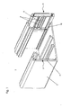
- FIG. 1 is a perspective view of a cable channel element 1 is shown.
- a coupling element 3 is introduced on the right side wall 2 of the cable channel element 1.
- guide ribs 10 are integrally formed in this embodiment, which allow a longitudinal displacement of the coupling elements 3 on the side wall 2 of the cable channel element 1.
- the coupling elements 3 are shown as shown on the left side wall 2 of the cable channel element 1, so pushed in that they do not protrude beyond the end face 11 of the cable channel element 1.
- the coupling elements 3 are to be moved to their working position, to which the coupling element 3 is pulled out of the cable channel element 1 until it is positioned approximately half along the side wall 2 of the cable element 1 and the thus released spring element 4, which protrudes in this position from the surface 6 of the coupling element 3, rests against the end face 11 of the cable channel element 1.
- the coupling element 3 through the still on the side wall 2 of the cable channel element 1 positioned a spring element 4 and the positioned on the end face 11 of the cable channel element 1 second spring element 4 is fixed.
- this mounting state can now be attached to the each about half of the cable channel element 1 protruding coupling element 3 another not shown here cable channel element 1, positioned and fixed, this is advantageously possible by a person in one-hand installation.
- the spring element 4 is not pushed back on the end face 11 of the cable channel element 1 during assembly of another cable channel element 1 in the original cable channel element 1.
- This simple installation of the cable channel elements 1 can be realized both with a coupling element 3 and with two oppositely arranged coupling elements 3.
- Another advantage of this cable channel systems according to the invention is that the coupling element 3 is made in this embodiment of a metallic material and thus in addition to a so-called equipotential bonding between two cable channel elements 1 to be connected is used.
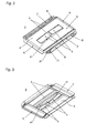
- FIG. 2 is a plan view of a coupling element 3 is shown.
- This coupling element 3 is made in this embodiment of a plastic.
- the coupling element 3 has two spring elements 4 in the center of the surface 6. These spring elements 4 are arranged opposite each other in a rectangular recess 61 of the surface 6 of the coupling element 3.
- the free ends of the spring elements 4 are arranged spaced apart, wherein the opposite these fixed ends of the spring elements 4 are integrally connected to the surface 6 of the coupling element 3.
- the spring elements 4 have in this embodiment a rectangular cross-section, wherein here are also further cross-sectional shapes within the scope of the invention.
- the spring elements 4 are formed by the surface 6 of the coupling element 3 wegragend, projecting in this embodiment, the spring elements 4 at an acute angle of about 20 ° from the surface 6 of the coupling element 3.
- the guide elements 7, 8 are arranged, which are arranged in this embodiment on both longitudinal sides of the coupling element 3.
- the guide elements 7, 8 have at their free ends run-on slopes 71, 81, which should ensure a simple and easy insertion of the coupling elements 3 in the cable channel elements 1.
- the run-on slope 71 of the guide element 7 is formed approximately orthogonal to the surface 6 of the coupling element 3, while the run-on slope 81 of the guide element 8 approximately at an acute angle to the stiffening element 5 of Coupling element 3 is formed.
- the run-on slopes 71, 81 of the guide elements 7, 8 are approximately curved, formed pointed, so that the coupling element 3 is easily displaced on both the side wall 2 and the guide ribs 10 of the cable channel element 1.
- Another advantage of the chamfers 71, 81 of the guide elements 7, 8 is seen in the fact that when attaching the coupling elements 3, a precise approach to the cable channel element 1 is possible.
- 3 end faces 9 are arranged at an acute angle to the narrow sides of the coupling element. This also allows easier insertion of the coupling element 3 in the cable channel element 1 and also facilitates the installation of a second cable channel element 1 on an already mounted cable duct element 1.
- the coupling element 3 in this embodiment has between the guide elements 7 and the spring elements 4 approximately parallel stiffening elements 5, which ensure a mechanical reinforcement of the coupling element 3 and a better displaceability.
- FIG. 3 is a view of the coupling element 3 shown from below.
- the spring elements 4 approximately in the middle stiffening elements 41 which ensure the required pressure of the spring elements 4 on the side wall 2 cable channel element 1, wherein by the geometry of the spring elements 4 and the stiffening elements 41 of the effectable pressure of the spring elements 4 of corresponding spatial shape of the cable channel element 1 is arbitrarily adaptable.
- reinforcing elements 5 are arranged on the surface opposite the surface 6 of the coupling element 3. These reinforcing elements 5 are formed both parallel to the spring elements and orthogonal to the spring elements 4 and ensure the required for the installation of a second cable channel element 1 stability while elasticity.
- the end face 9 of the coupling element 3 is arranged in the opposite direction to the projecting away from the surface 6 of the coupling element 3 spring elements 4, whereby on the one hand a better displaceability of the coupling element 3 is realized in the cable channel element 1 in the form of a handle slope and on the other hand a better installation introduction for a second cable duct element 1 to be mounted can be reached.
Landscapes
- Engineering & Computer Science (AREA)
- Architecture (AREA)
- Civil Engineering (AREA)
- Structural Engineering (AREA)
- Details Of Indoor Wiring (AREA)
Description
- Die Erfindung betrifft ein Kabelkanalsystem nach dem Oberbegriff des Anspruches 1. Diese werden für die Verlegung bzw. Installation von Elektroleitungen oder auch von Leitungen bzw. Kabel für Informations-/Kommunikationsnetze eingesetzt, wobei derartige Kabelkanalsysteme im wesentlich aus U-förmigen bzw. C-förmigen, einseitig offen ausgebildeten Profilen bestehen, wobei die offen ausgebildete Seite nach erfolgter Verlegung der Kabel bzw. Leitungen mittels einer zu dem Profil passenden Abdeckung verschlossen werden können.
- Derartige Kabelkanalsysteme sind in den einschlägigen Branchen allgemein bekannt, d.h. derartige Kabelkanalsysteme werden seit Jahren in großen Mengen hergestellt und montiert. Diese Kabelkanalsysteme sind je nach Einsatzbedingungen als Kunststoff-Extrusionsteile, als Aluminium-Strangpressteile oder als gekantete Stahlblech-Profile lieferbar.
- Dabei werden die Kabelkanalelemente in festen Längen von bspw. 2 m geliefert, so dass die eine zu verlegende größere Gesamtstrecke aus mehreren einzelnen Kabelkanalelementen zusammengesetzt werden muss, wobei der Bereich des Aneinanderfügens der Kabelkanalelemente eine Problemzone dahingehend bildet, dass bei der stirnseitigen Montage möglichst kein seitlicher Versatz zwischen den einzelnen Kabelkanalelementen eintreten darf.
- Für die Realisierung solcher stirnseitiger Verbindungen sind eine Reihe technischer Lösungen bekannt.
- So wird in der
EP-B 0 753 917 , derDE-U1 295 10 836 die Verwendung von Winkelstücken aus Metall zur Verstärkung von im Winkel verlegten Kabelkanalelementen beschrieben, wobei die Verstärkungen in vorgesehene Taschen in den auf Gehrung geschnittenen Enden der Kabelkanalelemente eingeschoben werden. - Weiterhin wird in der
EP-B1 0 721 243 eine Verbindungsmöglichkeit von zwei auf Stoß miteinander zu verbindenden Kabelkanalelementen beschrieben, bei der die Kupplungselemente aus Kunststoff zwischen dem Deckelverschluss-Profil und dem Boden des Unterteils des Kabelkanalelementes verklemmt werden, wobei auf der Innenseite des Boden des Kabelkanalelementes, parallel zu den Seitenwänden des Kabelkanalelementes, zusätzlich Längsleisten angeordnet sind, die einen Fuß der Kupplungselemente fixieren. - Neben den in der
DE-U1 299 10 683 angegebenen Nachteilen der bisher bekannten Verbindungselemente für diese Kabelkanalselemente besteht ein weiterer Nachteil darin, dass zur Fixierung der Kupplungselemente entsprechend eingeformte Prägungen am Unterteil des Kabelkanalelementes erforderlich sind. - Die Verwendung von metallischen Kupplungsstiften für das Verbinden von zwei Kabelkanalelementen aus bspw. Kunststoff hat den Nachteil, dass sich diese sehr leicht in den Kunststoff einarbeiten und sich so zu lockern beginnen, wobei dieser Prozess durch das Setzungsverhalten des Kunststoffs noch unterstützt wird.
- Weiterhin ist bei dieser Verbindungsart von Nachteil, dass diese losen metallischen Kupplungselemente gesondert gelagert und transportiert werden müssen, so dass es zum Teil passiert, dass nicht genügend Kupplungselemente auf der Baustelle vorrätig sind bzw. verlustig gehen können.
Außerdem sind derartige metallische Kupplungselemente verhältnismäßig teuer in der Herstellung und können wegen der Einbauverhältnisse (Leichtgängigkeit der Kupplungsstifte beim Einschieben der Stifte in die Wand des Kabelkanalelementes aus Kunststoff) nicht bereits vormontiert werden. Ein weiterer Nachteil dieser metallischen Kupplungselemente besteht in ihrer Korrosionsanfälligkeit. - Eine weitere Möglichkeit des stirnseitigen Aneinanderfügens derartiger Kabelkanalelemente besteht darin, dass bereits bei Herstellung der Kabelkanalelemente ein entsprechendes Kupplungselement mit angeformt wird.
Eine solche Verbindungsmöglichkeit hat zwar einerseits den Vorteil, dass keine separaten Bauteile für das stirnseitige Aneinanderfügen erforderlich sind, weist jedoch andererseits wiederum den Nachteil auf, dass durch die angeformten Kupplungselemente die Kanalelemente länger werden, wodurch sich wiederum Nachteile beim Transport und/oder der Lagerhaltung der Kabelkanalelemente ergeben. - Der vorliegenden Erfindung liegt daher die Aufgabe zu Grunde, ein Kabelkanalsystem der eingangs ausgeführten Art zu schaffen, welches die Nachteile des Standes der Technik überwindet und mit dem es möglich ist, einzelne Kabelkanalelemente in einfacher Art und Weise schnell, sicher und kostengünstig in der stirnseitigen Verbindung zu montieren und dadurch die Montagefreundlichkeit eines derartigen Kabelkanalsystems zu verbessern.
- Erfindungsgemäß wird diese Aufgabe durch die kennzeichnenden Merkmal des Anspruches 1 gelöst. Weitere vorteilhafte Ausführungen sind in den Unteransprüchen ausgeführt.
- Das erfindungsgemäße Kabelkanalsystem zeichnet sich dadurch aus, dass an den Endbereichen eines Kabelkanalelementes an mindestens einer der beiden Seitenwände ein Kupplungselement geführt ist, welches mindestens zwei Federelemente aufweist.
Im Lieferzustand sind die Kupplungselemente an der Seitenwand des Kabelkanalelementes anliegend angeordnet, wobei diese nicht über die Endbereiche des Kabelkanalelementes hinausragen. Im Montagezustand sind die Kupplungselemente jeweils etwa bis zur Hälfte längs der Seitenwand in das Kabelkanalelement eingeführt. Dadurch wird zum einen das Kupplungselement durch den Druck des einen Federelementes im Kabelkanalelement gehalten und zum anderen durch das noch zur Seitenwand des Kabelkanalelementes aufgebogene und Druck ausübende zweite Federelement gegen längsseitiges Verschieben durch das anzusetzende zweite Kabelkanalelement gesichert.
Im zusammengesetzten Zustand der Kabelkanalelemente werden die Kupplungselemente durch den von den Federzungen aufgebrachten Druck arretiert. - Als einer der wesentlichen Vorteile dieser erfindungsgemäßen Lösung ist die einfache Vormontage der Kupplungselemente und damit die schnelle stirnseitige Verbindung der beiden Kabelkanalelemente zu nennen, die auf Grund der an den Seitenwänden der Kabelkanalelemente eingebrachten Führungsrippen für die einzusetzenden Kupplungselemente erreicht werden.
Dabei ist es von Vorteil, dass die Federelemente über die Fläche des Kupplungselementes hinausragend ausgebildet sind, da so der erforderliche Druck für die Arretierung bewirkbar ist. In einer weiteren Ausführungsform sind die Federelemente in einem spitzen Winkel von der Fläche des Kupplungselementes wegragend ausgebildet. - Weiterhin wird auf Grund eines gemeinsamen Kupplungselementes für die stirnseitig aneinander zu fügenden Kabelkanalelemente eine nahezu selbstständige Justage an den Endbereichen erreicht. Die besondere Ausbildung des Kupplungselementes mit den Führungselementen an seinen Längsseiten und den vorteilhafter Weise angeformten Anlaufschrägen ermöglichen ein leichtes Montieren des Kabelkanalelemente des Kabelkanalsystems.
- Vorteilhafte Weiterbildungen und Ausgestaltungen der Erfindung sind aus dem nachfolgend an Hand der Figuren beschriebenen, die Erfindung nicht einschränkenden Ausführungsbeispielen ersichtlich.
- Es zeigen
-
Fig. 1 - eine perspektivische Darstellung eines Kabelkanalelementes im Montagezustand -
Fig. 2 - eine Draufsicht eines Kupplungselementes -
Fig. 3 - eine Ansicht des Kupplungselementes von unten - In der
Figur 1 ist eine perspektivische Darstellung eines Kabelkanalelementes 1 dargestellt. Für den Montagezustand wird an der rechten Seitenwand 2 des Kabelkanalelementes 1 ein Kupplungselement 3 eingebracht. An den Seitenwänden 2 sind in diesem Ausführungsbeispiel Führungsrippen 10 einstückig angeformt, die ein längsseitiges Verschieben der Kupplungselemente 3 an der Seitenwand 2 des Kabelkanalelementes 1 ermöglichen. Die Federelemente 4 des Kupplungselementes 3, die in einem spitzen Winkel von der Fläche 6 des Kupplungselementes 3 wegragen, üben im eingeschobenen Zustand einen Druck auf die Seitenwand 2 des Kabelkanalelementes 1 aus, so dass das Kupplungselement 3 arretiert und nicht verschiebbar angeordnet ist.
Im Lieferzustand sind die Kupplungselemente 3 wie an der linken Seitenwand 2 des Kabelkanalelementes 1 dargestellt, so hineingeschoben, dass diese nicht über die Stirnseite 11 des Kabelkanalelementes 1 hinausragen. Um den Montagezustand des Kabelkanalelementes 1 zu erreichen, sind die Kupplungselemente 3 in ihre Arbeitsstellung zu bewegen, wobei dazu das Kupplungselement 3 aus dem Kabelkanalelement 1 herausgezogen wird, bis es etwa zur Hälfte längs der Seitenwand 2 des Kabelelementes 1 positioniert ist und das damit freiwerdende Federelement 4, welches in dieser Position von der Fläche 6 des Kupplungselementes 3 wegragt, an der Stirnseite 11 des Kabelkanalelementes 1 anliegt. Somit ist das Kupplungselement 3 durch das noch an der Seitenwand 2 des Kabelkanalelementes 1 positionierte eine Federelement 4 und das an der Stirnseite 11 des Kabelkanalelementes 1 positionierte zweite Federelement 4 fixiert. In diesem Montagezustand kann nun an das jeweils etwa zur Hälfte aus dem Kabelkanalelement 1 herausragende Kupplungselement 3 ein weiteres hier nicht dargestelltes Kabelkanalelement 1 angesetzt, positioniert und fixiert werden, wobei dies vorteilhafterweise durch eine Person in Einhandmontage möglich ist.
Durch die Fixierung des Kupplungselementes 3 wird das Federelement 4 an der Stirnseite 11 des Kabelkanalelementes 1 bei der Montage eines weiteren Kabelkanalelementes 1 nicht in das ursprüngliche Kabelkanalelement 1 zurückgeschoben. Diese einfache Montage der Kabelkanalelemente 1 kann sowohl mit einem Kupplungselement 3 als auch mit zwei einander gegenüberliegend angeordneten Kupplungselementen 3 realisiert werden. Ein weiterer Vorteil dieser erfindungsgemäßen Kabelkanalsysteme besteht darin, dass das Kupplungselement 3 in diesem Ausführungsbeispiel aus einem metallischen Werkstoff ausgeführt ist und somit zu einem sogenannten Potenzialausgleich zwischen zwei zu verbindenden Kabelkanalelementen 1 zusätzlich nutzbar ist. - In
Figur 2 ist eine Draufsicht eines Kupplungselementes 3 dargestellt. Dieses Kupplungselement 3 ist in diesem Ausführungsbeispiel aus einem Kunststoff hergestellt. Das Kupplungselement 3 weist im Zentrum der Fläche 6 zwei Federelemente 4 auf. Diese Federelemente 4 sind in einer rechteckigen Aussparung 61 der Fläche 6 des Kupplungselementes 3 einander gegenüberliegend angeordnet. Die freien Enden der Federelemente 4 sind einander beanstandet angeordnet, wobei die diesen gegenüberliegenden festen Enden der Federelemente 4 einstückig mit der Fläche 6 des Kupplungselementes 3 verbunden sind. Die Federelemente 4 weisen in diesem Ausführungsbeispiel einen rechteckigen Querschnitt auf, wobei hier auch weitere Querschnittsformen im Rahmen der Erfindung liegen.
Die Federelemente 4 sind von der Fläche 6 des Kupplungselementes 3 wegragend ausgebildet, wobei in diesem Ausführungsbeispiel die Federelemente 4 in einem spitzen Winkel von ca. 20° von der Fläche 6 des Kupplungselementes 3 wegragen. An den Längsseiten des Kupplungselementes 3 sind die Führungselemente 7, 8 angeordnet, die in diesem Ausführungsbeispiel an beiden Längsseiten des Kupplungselementes 3 angeordnet sind. Die Führungselemente 7, 8 weisen an ihren freien Enden Anlaufschrägen 71, 81 auf, die ein leichtes und einfaches Einführen der Kupplungselemente 3 in die Kabelkanalelemente 1 gewährleisten sollen. Die Anlaufschräge 71 des Führungselementes 7 ist in etwa orthogonal zur Fläche 6 des Kupplungselementes 3 ausgebildet, während die Anlaufschräge 81 des Führungselementes 8 etwa in einen spitzen Winkel zum Versteifungselement 5 des Kupplungselementes 3 ausbildet ist. Die Anlaufschrägen 71, 81 der Führungselemente 7, 8 sind in etwa gekrümmt, spitzförmig verlaufend ausgebildet, so dass das Kupplungselement 3 sowohl an der Seitenwand 2 als auch den Führungsrippen 10 des Kabelkanalelementes 1 leicht verschiebbar ist. Ein weiterer Vorteil der Anlaufschrägen 71, 81 der Führungselemente 7, 8 wird darin gesehen, dass beim Ansetzen der Kupplungselemente 3 ein genauer Ansatz an dem Kabelkanalelement 1 möglich ist.
In diesem Ausführungsbeispiel sind an den schmalen Seiten des Kupplungselementes 3 Stirnseiten 9 in einem spitzen Winkel angeordnet. Damit wird ebenfalls ein leichteres Einführen des Kupplungselementes 3 in das Kabelkanalelement 1 ermöglicht und auch die Montage eines zweiten Kabelkanalelementes 1 an einem bereits montierten Kabelkanalelement 1 erleichtert. Das Kupplungselement 3 in diesem Ausführungsbeispiel weist zwischen den Führungselementen 7 und den Federelementen 4 etwa parallel verlaufende Versteifungselemente 5 auf, die eine mechanische Verstärkung des Kupplungselementes 3 und eine bessere Verschiebbarkeit gewährleisten. - In der
Figur 3 ist eine Ansicht des Kupplungselementes 3 von unten dargestellt. In dieser Darstellung ist erkennbar, dass die Federelemente 4 in etwa mittig Versteifungselemente 41 aufweisen, die den erforderlichen Druck der Federelemente 4 auf die Seitenwand 2 Kabelkanalelementes 1 gewährleisten, wobei durch die Geometrie der Federelemente 4 sowie der Versteifungselemente 41 der bewirkbare Druck der Federelemente 4 der entsprechenden Raumform des Kabelkanalelementes 1 beliebig anpassbar ist. Um die Stabilität des Kupplungselementes 3 weiter zu optimieren, sind Verstärkungselemente 5 auf der der Fläche 6 des Kupplungselementes 3 gegenüberliegenden Fläche angeordnet.
Diese Verstärkungselemente 5 sind sowohl parallel zu den Federelementen als auch orthogonal zu den Federelementen 4 ausgebildet und gewährleisten die für die Montage eines zweiten Kabelkanalelementes 1 erforderliche Stabilität bei gleichzeitiger Elastizität. In diesem Ausführungsbeispiel ist die Stirnseite 9 des Kupplungselementes 3 in entgegengesetzter Richtung zu den von der Fläche 6 des Kupplungselementes 3 wegragenden Federelementen 4 angeordnet, wodurch einerseits eine bessere Verschiebbarkeit des Kupplungselementes 3 im Kabelkanalelement 1 in Form einer Griffschräge realisiert ist und andererseits eine bessere Montageeinführung für ein zweites zu montierendes Kabelkanalelement 1 erreichbar ist.
Claims (14)
- Kabelkanalsystem bestehend aus mindestens zwei Kabelkanalelementen, welche mittels separater Verbindungselemente in ihrer Längsrichtung aneinander fügbar sind, wobei die Kabelkanalelemente aus einem annähernd U-förmigen Kanalunterteil sowie einer vorzugsweise aufrastbaren Abdeckung bestehen und das Verbindungselement lösbar und / oder verschiebbar in die freien Endbereiche der Kabelkanalelemente einsetzbar ist, wobei an den Endbereichen eines Kabelkanalelementes (1) an mindestens einer der beiden Seitenwände (2) ein Kupplungselement (3) geführt ist, welches wenigstens zwei Federelemente (4) aufweist.
dadurch gekennzeichnet,
dass die Federelemente (4) in einer rechteckigen Aussparung (61) in einer Fläche (6) des Kupplungselements (3) einander gegenüber liegend angeordnet sind, wobei die freien Enden der Federelemente (4) des Kupplungselementes (3) voneinander beabstandet angeordnet sind. - Kabelkanalsystem nach Anspruch 1, dadurch gekennzeichnet, dass das Kupplungselement (3) im Lieferzustand so an der Seitenwand (2) des Kabelkanalelementes (1) anliegend angeordnet ist, dass diese nicht über den Endbereich des Kabelkanalelementes (1) herausragt.
- Kabelkanalsystem nach Anspruch 1 und 2, dadurch gekennzeichnet, dass das Kupplungselement (3) im Montagezustand jeweils bis etwa zur Hälfte längs der Seitenwand (2) in die Endbereiche des Kabelkanalelementes (1) eingeführt und durch den von dem Federelement (4) aufgebrachten Druck arretierbar ist.
- Kabelkanalsystem nach Anspruch 1 bis 3, dadurch gekennzeichnet, dass die Federelemente (4) des Kupplungselementes (3) auf der zur Seitenwand (2) des Kabelkanalelementes (1) weisenden Seite von der Fläche (6) wegweisend ausgebildet sind.
- Kabelkanalsystem nach Anspruch 1 bis 4, dadurch gekennzeichnet, dass die Federelemente (4) des Kupplungselementes (3) in etwa einem spitzen Winkel von der Fläche (6) des Kupplungselementes (3) wegragend angeordnet sind.
- Kabelkanalsystem nach Anspruch 1 bis 5, dadurch gekennzeichnet, dass an dem Federelement (4) des Kupplungselementes (3) wenigstens ein Versteifungselement (41) angeordnet ist.
- Kabelkanalsystem nach Anspruch 1 bis 6, dadurch gekennzeichnet, dass auf der der Fläche (6) des Kupplungselementes (3) gegenüberliegenden Fläche Versteifungselemente (5) angeordnet sind.
- Kabelkanalsystem nach Anspruch 1 bis 7, dadurch gekennzeichnet, dass das Kupplungselement (3) an seiner Längsseite etwa parallel zu den Federelementen (4) wenigstens ein Führungselement (7, 8) aufweist.
- Kabelkanalsystem nach Anspruch 8, dadurch gekennzeichnet, dass die freien Enden der Führungselemente (7, 8) als Anlaufschrägen (71, 81) ausgebildet sind.
- Kabelkanalsystem nach Anspruch 9, dadurch gekennzeichnet, dass jeweils eine Anlaufschräge (71) etwa orthogonal zur Fläche (6) des Kupplungselementes (3) ausgebildet ist.
- Kabelkanalsystem nach Anspruch 9 bis 10, dadurch gekennzeichnet, dass jeweils eine Anlaufschräge (81) etwa in einem spitzen Winkel zum Versteifungselement (5) des Kupplungselementes (3) ausgebildet ist.
- Kabelkanalsystem nach Anspruch 9 bis 11, dadurch gekennzeichnet, dass die Anlaufschräge (71, 81) der Führungselemente (7, 8) in etwa gekrümmt spitzförmig verlaufend ausgebildet ist.
- Kabelkanalsystem nach einem der vorhergehenden Ansprüche, dadurch gekennzeichnet, dass die Stirnseite (9) in etwa einem spitzen Winkel an den Kupplungselement (3) angeordnet ist.
- Kabelkanalsystem nach Anspruch 13, dadurch gekennzeichnet, dass die Stirnseite (9) in entgegengesetzte Richtung zu den Federelementen (4) vom Kupplungselement (3) wegragend angeordnet sind.
Applications Claiming Priority (2)
| Application Number | Priority Date | Filing Date | Title |
|---|---|---|---|
| DE200420005987 DE202004005987U1 (de) | 2004-04-16 | 2004-04-16 | Kabelkanalsystem |
| DE202004005987U | 2004-04-16 |
Publications (3)
| Publication Number | Publication Date |
|---|---|
| EP1587195A2 EP1587195A2 (de) | 2005-10-19 |
| EP1587195A3 EP1587195A3 (de) | 2009-10-21 |
| EP1587195B1 true EP1587195B1 (de) | 2013-10-16 |
Family
ID=32478615
Family Applications (1)
| Application Number | Title | Priority Date | Filing Date |
|---|---|---|---|
| EP20050005437 Expired - Lifetime EP1587195B1 (de) | 2004-04-16 | 2005-03-12 | Kabelkanalsystem |
Country Status (2)
| Country | Link |
|---|---|
| EP (1) | EP1587195B1 (de) |
| DE (1) | DE202004005987U1 (de) |
Families Citing this family (8)
| Publication number | Priority date | Publication date | Assignee | Title |
|---|---|---|---|---|
| DE202007009424U1 (de) * | 2007-07-05 | 2008-11-06 | Tehalit Gmbh | Erdungsklammer zum Potentialausgleich von Leitungsführungskanälen |
| ES2307446B2 (es) * | 2008-04-04 | 2009-07-21 | Schneider Electric España, S.A | Brida de union rapida para canalizaciones electricas. |
| DE202010015292U1 (de) | 2010-11-10 | 2012-02-14 | Tehalit Gmbh | Kupplungselement mit Erdungsfunktion |
| DE202011106065U1 (de) | 2011-09-23 | 2013-01-11 | Tehalit Gmbh | Kupplungselement mit Erdungsfunktion für Leitungsführungskanäle |
| EP2637272A1 (de) * | 2012-03-08 | 2013-09-11 | GGK GmbH & Co. KG | Verbindungsvorrichtung |
| DE202012100869U1 (de) * | 2012-03-12 | 2012-03-26 | Rehau Ag + Co | Kabelkanalsystem |
| DE202012100866U1 (de) * | 2012-03-12 | 2012-05-02 | Rehau Ag + Co | Kabelkanalsystem |
| DE202017106070U1 (de) * | 2017-10-06 | 2019-01-10 | Obo Bettermann Gmbh & Co. Kg | Brandschutzkanalstoßabdichtung |
Family Cites Families (3)
| Publication number | Priority date | Publication date | Assignee | Title |
|---|---|---|---|---|
| DE29910683U1 (de) * | 1999-06-18 | 2000-11-23 | Tehalit GmbH, 67716 Heltersberg | Leitungsführungskanal |
| US6523791B2 (en) * | 2000-06-01 | 2003-02-25 | Panduit Corp. | Cable duct coupler |
| US7250574B2 (en) * | 2002-08-19 | 2007-07-31 | Fox Ronald W | Cable trough |
-
2004
- 2004-04-16 DE DE200420005987 patent/DE202004005987U1/de not_active Expired - Lifetime
-
2005
- 2005-03-12 EP EP20050005437 patent/EP1587195B1/de not_active Expired - Lifetime
Also Published As
| Publication number | Publication date |
|---|---|
| EP1587195A2 (de) | 2005-10-19 |
| DE202004005987U1 (de) | 2004-06-03 |
| EP1587195A3 (de) | 2009-10-21 |
Similar Documents
| Publication | Publication Date | Title |
|---|---|---|
| WO2013050168A1 (de) | Photovoltaikgestell, pfettenbaugruppe und verbindungsteil | |
| EP3452667B1 (de) | Rinne zur oberflächenentwässerung mit einer stirnwand | |
| DE102019135726A1 (de) | Halterahmen für einen Steckverbinder | |
| EP1587195B1 (de) | Kabelkanalsystem | |
| EP2228503A1 (de) | Paneele | |
| EP1767716A2 (de) | Halteelement für Gitter | |
| EP2138145A2 (de) | Verkleidung einer höhenverstellbaren Stützsäule | |
| DE69409783T2 (de) | Universelle Halterung, insbesondere für die Befestigung einer elektrischen Ausrüstung | |
| EP0404726A2 (de) | Vorrichtung zum Verbinden von C-förmigen Schienen, insbesondere Montageschienen | |
| DE3631183A1 (de) | Energiefuehrungsschlauch | |
| DE102014106068B4 (de) | Vorrichtung zur Verbindung zweier einander gegenüberliegender plattenförmiger Schalungselemente | |
| EP2625346B1 (de) | Metallische deckenunterkonstruktion | |
| DE202010007139U1 (de) | Vorrichtung zur Befestigung eines Moduls zur Nutzung von Sonnenenergie | |
| DE202010010424U1 (de) | Wanddurchführungsklemme für elektrische Leiter | |
| CH429111A (de) | Mehrteilige Leiste | |
| DE202010004995U1 (de) | Befestiger zur Befestigung eines ersten Bauteils an einem zweiten Bauteil | |
| DE3606812A1 (de) | Verkleidung fuer einen einstiegsschweller eines kraftfahrzeugs | |
| EP2273638A2 (de) | Klammer für Kabelkanäle zur Kaschierung von Schnittkanten | |
| EP1780345B1 (de) | Verbinder für rinnenförmige Profilstäbe und Verbindungsanordnung | |
| EP3427572A1 (de) | Einfassung zum aufnehmen von erd- und/oder kompostmaterial | |
| DE19846668A1 (de) | Sicherungsvorrichtung für eine Entwässerungsrinne | |
| DE2804419A1 (de) | Installationskanal | |
| DE20200268U1 (de) | Paneelelement | |
| DE7803034U1 (de) | Installationskanal | |
| EP1220400A1 (de) | Installationskanal mit Stossstellenverbinder |
Legal Events
| Date | Code | Title | Description |
|---|---|---|---|
| PUAI | Public reference made under article 153(3) epc to a published international application that has entered the european phase |
Free format text: ORIGINAL CODE: 0009012 |
|
| AK | Designated contracting states |
Kind code of ref document: A2 Designated state(s): AT BE BG CH CY CZ DE DK EE ES FI FR GB GR HU IE IS IT LI LT LU MC NL PL PT RO SE SI SK TR |
|
| AX | Request for extension of the european patent |
Extension state: AL BA HR LV MK YU |
|
| PUAL | Search report despatched |
Free format text: ORIGINAL CODE: 0009013 |
|
| AK | Designated contracting states |
Kind code of ref document: A3 Designated state(s): AT BE BG CH CY CZ DE DK EE ES FI FR GB GR HU IE IS IT LI LT LU MC NL PL PT RO SE SI SK TR |
|
| AX | Request for extension of the european patent |
Extension state: AL BA HR LV MK YU |
|
| 17P | Request for examination filed |
Effective date: 20100311 |
|
| AKX | Designation fees paid |
Designated state(s): AT BE BG CH CY CZ DE DK EE ES FI FR GB GR HU IE IS IT LI LT LU MC NL PL PT RO SE SI SK TR |
|
| 17Q | First examination report despatched |
Effective date: 20120319 |
|
| GRAP | Despatch of communication of intention to grant a patent |
Free format text: ORIGINAL CODE: EPIDOSNIGR1 |
|
| INTG | Intention to grant announced |
Effective date: 20130426 |
|
| GRAS | Grant fee paid |
Free format text: ORIGINAL CODE: EPIDOSNIGR3 |
|
| GRAA | (expected) grant |
Free format text: ORIGINAL CODE: 0009210 |
|
| AK | Designated contracting states |
Kind code of ref document: B1 Designated state(s): AT BE BG CH CY CZ DE DK EE ES FI FR GB GR HU IE IS IT LI LT LU MC NL PL PT RO SE SI SK TR |
|
| REG | Reference to a national code |
Ref country code: GB Ref legal event code: FG4D Free format text: NOT ENGLISH |
|
| REG | Reference to a national code |
Ref country code: CH Ref legal event code: EP |
|
| REG | Reference to a national code |
Ref country code: IE Ref legal event code: FG4D Free format text: LANGUAGE OF EP DOCUMENT: GERMAN |
|
| REG | Reference to a national code |
Ref country code: AT Ref legal event code: REF Ref document number: 636902 Country of ref document: AT Kind code of ref document: T Effective date: 20131115 |
|
| REG | Reference to a national code |
Ref country code: DE Ref legal event code: R096 Ref document number: 502005014026 Country of ref document: DE Effective date: 20131205 |
|
| REG | Reference to a national code |
Ref country code: NL Ref legal event code: VDEP Effective date: 20131016 |
|
| REG | Reference to a national code |
Ref country code: LT Ref legal event code: MG4D |
|
| PG25 | Lapsed in a contracting state [announced via postgrant information from national office to epo] |
Ref country code: IS Free format text: LAPSE BECAUSE OF FAILURE TO SUBMIT A TRANSLATION OF THE DESCRIPTION OR TO PAY THE FEE WITHIN THE PRESCRIBED TIME-LIMIT Effective date: 20140216 Ref country code: NL Free format text: LAPSE BECAUSE OF FAILURE TO SUBMIT A TRANSLATION OF THE DESCRIPTION OR TO PAY THE FEE WITHIN THE PRESCRIBED TIME-LIMIT Effective date: 20131016 Ref country code: SE Free format text: LAPSE BECAUSE OF FAILURE TO SUBMIT A TRANSLATION OF THE DESCRIPTION OR TO PAY THE FEE WITHIN THE PRESCRIBED TIME-LIMIT Effective date: 20131016 Ref country code: LT Free format text: LAPSE BECAUSE OF FAILURE TO SUBMIT A TRANSLATION OF THE DESCRIPTION OR TO PAY THE FEE WITHIN THE PRESCRIBED TIME-LIMIT Effective date: 20131016 Ref country code: FI Free format text: LAPSE BECAUSE OF FAILURE TO SUBMIT A TRANSLATION OF THE DESCRIPTION OR TO PAY THE FEE WITHIN THE PRESCRIBED TIME-LIMIT Effective date: 20131016 |
|
| PG25 | Lapsed in a contracting state [announced via postgrant information from national office to epo] |
Ref country code: CY Free format text: LAPSE BECAUSE OF FAILURE TO SUBMIT A TRANSLATION OF THE DESCRIPTION OR TO PAY THE FEE WITHIN THE PRESCRIBED TIME-LIMIT Effective date: 20131016 Ref country code: ES Free format text: LAPSE BECAUSE OF FAILURE TO SUBMIT A TRANSLATION OF THE DESCRIPTION OR TO PAY THE FEE WITHIN THE PRESCRIBED TIME-LIMIT Effective date: 20131016 |
|
| PG25 | Lapsed in a contracting state [announced via postgrant information from national office to epo] |
Ref country code: PT Free format text: LAPSE BECAUSE OF FAILURE TO SUBMIT A TRANSLATION OF THE DESCRIPTION OR TO PAY THE FEE WITHIN THE PRESCRIBED TIME-LIMIT Effective date: 20140217 |
|
| REG | Reference to a national code |
Ref country code: DE Ref legal event code: R097 Ref document number: 502005014026 Country of ref document: DE |
|
| PG25 | Lapsed in a contracting state [announced via postgrant information from national office to epo] |
Ref country code: EE Free format text: LAPSE BECAUSE OF FAILURE TO SUBMIT A TRANSLATION OF THE DESCRIPTION OR TO PAY THE FEE WITHIN THE PRESCRIBED TIME-LIMIT Effective date: 20131016 |
|
| PLBE | No opposition filed within time limit |
Free format text: ORIGINAL CODE: 0009261 |
|
| STAA | Information on the status of an ep patent application or granted ep patent |
Free format text: STATUS: NO OPPOSITION FILED WITHIN TIME LIMIT |
|
| PG25 | Lapsed in a contracting state [announced via postgrant information from national office to epo] |
Ref country code: IT Free format text: LAPSE BECAUSE OF FAILURE TO SUBMIT A TRANSLATION OF THE DESCRIPTION OR TO PAY THE FEE WITHIN THE PRESCRIBED TIME-LIMIT Effective date: 20131016 Ref country code: PL Free format text: LAPSE BECAUSE OF FAILURE TO SUBMIT A TRANSLATION OF THE DESCRIPTION OR TO PAY THE FEE WITHIN THE PRESCRIBED TIME-LIMIT Effective date: 20131016 Ref country code: RO Free format text: LAPSE BECAUSE OF FAILURE TO SUBMIT A TRANSLATION OF THE DESCRIPTION OR TO PAY THE FEE WITHIN THE PRESCRIBED TIME-LIMIT Effective date: 20131016 Ref country code: CZ Free format text: LAPSE BECAUSE OF FAILURE TO SUBMIT A TRANSLATION OF THE DESCRIPTION OR TO PAY THE FEE WITHIN THE PRESCRIBED TIME-LIMIT Effective date: 20131016 Ref country code: SK Free format text: LAPSE BECAUSE OF FAILURE TO SUBMIT A TRANSLATION OF THE DESCRIPTION OR TO PAY THE FEE WITHIN THE PRESCRIBED TIME-LIMIT Effective date: 20131016 |
|
| 26N | No opposition filed |
Effective date: 20140717 |
|
| PG25 | Lapsed in a contracting state [announced via postgrant information from national office to epo] |
Ref country code: DK Free format text: LAPSE BECAUSE OF FAILURE TO SUBMIT A TRANSLATION OF THE DESCRIPTION OR TO PAY THE FEE WITHIN THE PRESCRIBED TIME-LIMIT Effective date: 20131016 |
|
| REG | Reference to a national code |
Ref country code: DE Ref legal event code: R097 Ref document number: 502005014026 Country of ref document: DE Effective date: 20140717 |
|
| PG25 | Lapsed in a contracting state [announced via postgrant information from national office to epo] |
Ref country code: LU Free format text: LAPSE BECAUSE OF FAILURE TO SUBMIT A TRANSLATION OF THE DESCRIPTION OR TO PAY THE FEE WITHIN THE PRESCRIBED TIME-LIMIT Effective date: 20140312 |
|
| REG | Reference to a national code |
Ref country code: CH Ref legal event code: PL |
|
| REG | Reference to a national code |
Ref country code: IE Ref legal event code: MM4A |
|
| PG25 | Lapsed in a contracting state [announced via postgrant information from national office to epo] |
Ref country code: IE Free format text: LAPSE BECAUSE OF NON-PAYMENT OF DUE FEES Effective date: 20140312 Ref country code: CH Free format text: LAPSE BECAUSE OF NON-PAYMENT OF DUE FEES Effective date: 20140331 Ref country code: LI Free format text: LAPSE BECAUSE OF NON-PAYMENT OF DUE FEES Effective date: 20140331 |
|
| PG25 | Lapsed in a contracting state [announced via postgrant information from national office to epo] |
Ref country code: SI Free format text: LAPSE BECAUSE OF FAILURE TO SUBMIT A TRANSLATION OF THE DESCRIPTION OR TO PAY THE FEE WITHIN THE PRESCRIBED TIME-LIMIT Effective date: 20131016 |
|
| REG | Reference to a national code |
Ref country code: FR Ref legal event code: PLFP Year of fee payment: 11 |
|
| REG | Reference to a national code |
Ref country code: AT Ref legal event code: MM01 Ref document number: 636902 Country of ref document: AT Kind code of ref document: T Effective date: 20140312 |
|
| PGFP | Annual fee paid to national office [announced via postgrant information from national office to epo] |
Ref country code: GB Payment date: 20150325 Year of fee payment: 11 Ref country code: FR Payment date: 20150319 Year of fee payment: 11 |
|
| PG25 | Lapsed in a contracting state [announced via postgrant information from national office to epo] |
Ref country code: AT Free format text: LAPSE BECAUSE OF NON-PAYMENT OF DUE FEES Effective date: 20140312 |
|
| PG25 | Lapsed in a contracting state [announced via postgrant information from national office to epo] |
Ref country code: MC Free format text: LAPSE BECAUSE OF FAILURE TO SUBMIT A TRANSLATION OF THE DESCRIPTION OR TO PAY THE FEE WITHIN THE PRESCRIBED TIME-LIMIT Effective date: 20131016 Ref country code: BG Free format text: LAPSE BECAUSE OF FAILURE TO SUBMIT A TRANSLATION OF THE DESCRIPTION OR TO PAY THE FEE WITHIN THE PRESCRIBED TIME-LIMIT Effective date: 20131016 |
|
| PG25 | Lapsed in a contracting state [announced via postgrant information from national office to epo] |
Ref country code: GR Free format text: LAPSE BECAUSE OF FAILURE TO SUBMIT A TRANSLATION OF THE DESCRIPTION OR TO PAY THE FEE WITHIN THE PRESCRIBED TIME-LIMIT Effective date: 20140117 |
|
| PG25 | Lapsed in a contracting state [announced via postgrant information from national office to epo] |
Ref country code: TR Free format text: LAPSE BECAUSE OF FAILURE TO SUBMIT A TRANSLATION OF THE DESCRIPTION OR TO PAY THE FEE WITHIN THE PRESCRIBED TIME-LIMIT Effective date: 20131016 Ref country code: HU Free format text: LAPSE BECAUSE OF FAILURE TO SUBMIT A TRANSLATION OF THE DESCRIPTION OR TO PAY THE FEE WITHIN THE PRESCRIBED TIME-LIMIT; INVALID AB INITIO Effective date: 20050312 Ref country code: BE Free format text: LAPSE BECAUSE OF FAILURE TO SUBMIT A TRANSLATION OF THE DESCRIPTION OR TO PAY THE FEE WITHIN THE PRESCRIBED TIME-LIMIT Effective date: 20140331 |
|
| GBPC | Gb: european patent ceased through non-payment of renewal fee |
Effective date: 20160312 |
|
| REG | Reference to a national code |
Ref country code: FR Ref legal event code: ST Effective date: 20161130 |
|
| PG25 | Lapsed in a contracting state [announced via postgrant information from national office to epo] |
Ref country code: FR Free format text: LAPSE BECAUSE OF NON-PAYMENT OF DUE FEES Effective date: 20160331 Ref country code: GB Free format text: LAPSE BECAUSE OF NON-PAYMENT OF DUE FEES Effective date: 20160312 |
|
| PGFP | Annual fee paid to national office [announced via postgrant information from national office to epo] |
Ref country code: DE Payment date: 20170331 Year of fee payment: 13 |
|
| REG | Reference to a national code |
Ref country code: DE Ref legal event code: R119 Ref document number: 502005014026 Country of ref document: DE |
|
| PG25 | Lapsed in a contracting state [announced via postgrant information from national office to epo] |
Ref country code: DE Free format text: LAPSE BECAUSE OF NON-PAYMENT OF DUE FEES Effective date: 20181002 |