EP1587195B1 - Système de canalisation pour câble - Google Patents
Système de canalisation pour câble Download PDFInfo
- Publication number
- EP1587195B1 EP1587195B1 EP20050005437 EP05005437A EP1587195B1 EP 1587195 B1 EP1587195 B1 EP 1587195B1 EP 20050005437 EP20050005437 EP 20050005437 EP 05005437 A EP05005437 A EP 05005437A EP 1587195 B1 EP1587195 B1 EP 1587195B1
- Authority
- EP
- European Patent Office
- Prior art keywords
- cable duct
- coupling element
- elements
- duct system
- cable channel
- Prior art date
- Legal status (The legal status is an assumption and is not a legal conclusion. Google has not performed a legal analysis and makes no representation as to the accuracy of the status listed.)
- Not-in-force
Links
Images
Classifications
-
- H—ELECTRICITY
- H02—GENERATION; CONVERSION OR DISTRIBUTION OF ELECTRIC POWER
- H02G—INSTALLATION OF ELECTRIC CABLES OR LINES, OR OF COMBINED OPTICAL AND ELECTRIC CABLES OR LINES
- H02G3/00—Installations of electric cables or lines or protective tubing therefor in or on buildings, equivalent structures or vehicles
- H02G3/02—Details
- H02G3/06—Joints for connecting lengths of protective tubing or channels, to each other or to casings, e.g. to distribution boxes; Ensuring electrical continuity in the joint
- H02G3/0608—Joints for connecting non cylindrical conduits, e.g. channels
Definitions
- the invention relates to a cable duct system according to the preamble of claim 1. These are used for the installation or installation of electrical cables or cables or cables for information / communication networks, such cable channel systems essentially from U-shaped or C-shaped , one-sided open formed profiles, wherein the open side formed after installation of the cables or lines can be closed by means of a matching profile to the cover.
- Such conduit systems are well known in the relevant industries, i. Such cable duct systems have been manufactured and assembled in large quantities for years. Depending on the conditions of use, these cable duct systems can be supplied as plastic extruded parts, as extruded aluminum parts or as folded sheet steel profiles.
- the cable channel elements are supplied in fixed lengths of, for example, 2 m, so that the one to be laid greater total distance must be composed of several individual cable channel elements, wherein the region of Anventhegens the cable channel elements forms a problem zone to the effect that in the frontal mounting as possible no lateral Offset between the individual cable channel elements may occur.
- the present invention is therefore based on the object to provide a cable duct system of the initially described type, which overcomes the disadvantages of the prior art and with which it is possible individual cable channel elements in a simple manner quickly, safely and inexpensively in the frontal connection mount and thereby improve the ease of installation of such a cable duct system.
- the cable duct system according to the invention is characterized in that at the end regions of a cable channel element at least one of the two side walls, a coupling element is guided, which has at least two spring elements.
- the coupling elements are arranged on the side wall of the cable channel element fitting, which do not protrude beyond the end portions of the cable channel element.
- the coupling elements are each introduced about halfway along the side wall in the cable channel element.
- the coupling element is held by the pressure of a spring element in the cable channel element and secured to the other by the still bent to the side wall of the cable channel element and pressure exerting second spring element against longitudinal displacement by the second cable channel element to be attached.
- the coupling elements are locked by the pressure applied by the spring tongues.
- One of the main advantages of this solution according to the invention is the simple pre-assembly of the coupling elements and thus the fast frontal connection of the two cable channel elements to be achieved, which are achieved due to the introduced on the side walls of the cable channel elements guide ribs for the coupling elements to be used. It is advantageous that the spring elements are formed projecting beyond the surface of the coupling element, since the required pressure for locking can be effected. In a further embodiment, the spring elements are formed at an acute angle of the surface of the coupling element wegragend.
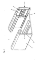
- FIG. 1 is a perspective view of a cable channel element 1 is shown.
- a coupling element 3 is introduced on the right side wall 2 of the cable channel element 1.
- guide ribs 10 are integrally formed in this embodiment, which allow a longitudinal displacement of the coupling elements 3 on the side wall 2 of the cable channel element 1.
- the coupling elements 3 are shown as shown on the left side wall 2 of the cable channel element 1, so pushed in that they do not protrude beyond the end face 11 of the cable channel element 1.
- the coupling elements 3 are to be moved to their working position, to which the coupling element 3 is pulled out of the cable channel element 1 until it is positioned approximately half along the side wall 2 of the cable element 1 and the thus released spring element 4, which protrudes in this position from the surface 6 of the coupling element 3, rests against the end face 11 of the cable channel element 1.
- the coupling element 3 through the still on the side wall 2 of the cable channel element 1 positioned a spring element 4 and the positioned on the end face 11 of the cable channel element 1 second spring element 4 is fixed.
- this mounting state can now be attached to the each about half of the cable channel element 1 protruding coupling element 3 another not shown here cable channel element 1, positioned and fixed, this is advantageously possible by a person in one-hand installation.
- the spring element 4 is not pushed back on the end face 11 of the cable channel element 1 during assembly of another cable channel element 1 in the original cable channel element 1.
- This simple installation of the cable channel elements 1 can be realized both with a coupling element 3 and with two oppositely arranged coupling elements 3.
- Another advantage of this cable channel systems according to the invention is that the coupling element 3 is made in this embodiment of a metallic material and thus in addition to a so-called equipotential bonding between two cable channel elements 1 to be connected is used.
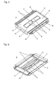
- FIG. 2 is a plan view of a coupling element 3 is shown.
- This coupling element 3 is made in this embodiment of a plastic.
- the coupling element 3 has two spring elements 4 in the center of the surface 6. These spring elements 4 are arranged opposite each other in a rectangular recess 61 of the surface 6 of the coupling element 3.
- the free ends of the spring elements 4 are arranged spaced apart, wherein the opposite these fixed ends of the spring elements 4 are integrally connected to the surface 6 of the coupling element 3.
- the spring elements 4 have in this embodiment a rectangular cross-section, wherein here are also further cross-sectional shapes within the scope of the invention.
- the spring elements 4 are formed by the surface 6 of the coupling element 3 wegragend, projecting in this embodiment, the spring elements 4 at an acute angle of about 20 ° from the surface 6 of the coupling element 3.
- the guide elements 7, 8 are arranged, which are arranged in this embodiment on both longitudinal sides of the coupling element 3.
- the guide elements 7, 8 have at their free ends run-on slopes 71, 81, which should ensure a simple and easy insertion of the coupling elements 3 in the cable channel elements 1.
- the run-on slope 71 of the guide element 7 is formed approximately orthogonal to the surface 6 of the coupling element 3, while the run-on slope 81 of the guide element 8 approximately at an acute angle to the stiffening element 5 of Coupling element 3 is formed.
- the run-on slopes 71, 81 of the guide elements 7, 8 are approximately curved, formed pointed, so that the coupling element 3 is easily displaced on both the side wall 2 and the guide ribs 10 of the cable channel element 1.
- Another advantage of the chamfers 71, 81 of the guide elements 7, 8 is seen in the fact that when attaching the coupling elements 3, a precise approach to the cable channel element 1 is possible.
- 3 end faces 9 are arranged at an acute angle to the narrow sides of the coupling element. This also allows easier insertion of the coupling element 3 in the cable channel element 1 and also facilitates the installation of a second cable channel element 1 on an already mounted cable duct element 1.
- the coupling element 3 in this embodiment has between the guide elements 7 and the spring elements 4 approximately parallel stiffening elements 5, which ensure a mechanical reinforcement of the coupling element 3 and a better displaceability.
- FIG. 3 is a view of the coupling element 3 shown from below.
- the spring elements 4 approximately in the middle stiffening elements 41 which ensure the required pressure of the spring elements 4 on the side wall 2 cable channel element 1, wherein by the geometry of the spring elements 4 and the stiffening elements 41 of the effectable pressure of the spring elements 4 of corresponding spatial shape of the cable channel element 1 is arbitrarily adaptable.
- reinforcing elements 5 are arranged on the surface opposite the surface 6 of the coupling element 3. These reinforcing elements 5 are formed both parallel to the spring elements and orthogonal to the spring elements 4 and ensure the required for the installation of a second cable channel element 1 stability while elasticity.
- the end face 9 of the coupling element 3 is arranged in the opposite direction to the projecting away from the surface 6 of the coupling element 3 spring elements 4, whereby on the one hand a better displaceability of the coupling element 3 is realized in the cable channel element 1 in the form of a handle slope and on the other hand a better installation introduction for a second cable duct element 1 to be mounted can be reached.
Landscapes
- Engineering & Computer Science (AREA)
- Architecture (AREA)
- Civil Engineering (AREA)
- Structural Engineering (AREA)
- Details Of Indoor Wiring (AREA)
Claims (14)
- Système de chemin de câble, constitué d'au moins deux éléments de chemin de câble, qui peuvent être assemblés l'un à l'autre dans leur direction longitudinale au moyen d'éléments de liaison séparés, les éléments de chemin de câble se composant d'une partie inférieure de chemin approximativement en forme de U ainsi que d'un recouvrement pouvant être de préférence encliqueté et l'élément de liaison pouvant être inséré de manière détachable et/ou coulissante dans les régions d'extrémité libre des éléments de chemin de câble, un élément d'accouplement (3) étant guidé au niveau des régions d'extrémité d'un élément de chemin de câble (1) au niveau d'au moins l'une des deux parois latérales (2), lequel élément d'accouplement présente au moins deux éléments de ressort (4), caractérisé en ce que les éléments de ressort (4) sont disposés en regard l'un de l'autre dans un évidement rectangulaire (61) dans une surface (6) de l'élément d'accouplement (3), les extrémités libres des éléments de ressort (4) de l'élément d'accouplement (3) étant disposées à distance les unes des autres.
- Système de chemin de câble selon la revendication 1, caractérisé en ce que l'élément d'accouplement (3), dans l'état fourni, est disposé de manière à s'appliquer contre la paroi latérale (2) de l'élément de chemin de câble (1) de telle sorte que celle-ci ne dépasse pas de la région d'extrémité de l'élément de chemin de câble (1).
- Système de chemin de câble selon les revendications 1 et 2, caractérisé en ce que l'élément d'accouplement (3), dans l'état de montage, est introduit à chaque fois jusqu'à approximativement la moitié le long de la paroi latérale (2) dans les régions d'extrémité de l'élément de chemin de câble (1) et peut être bloqué par la pression appliquée par l'élément de ressort (4).
- Système de chemin de câble selon les revendications 1 à 3, caractérisé en ce que les éléments de ressort (4) de l'élément d'accouplement (3) sont réalisés sur le côté tourné vers la paroi latérale (2) de l'élément de chemin de câble (1) en étant tournés à l'écart de la surface (6).
- Système de chemin de câble selon les revendications 1 à 4, caractérisé en ce que les éléments de ressort (4) de l'élément d'accouplement (3) sont disposés approximativement suivant un angle aigu en faisant saillie à l'écart de la surface (6) de l'élément d'accouplement (3).
- Système de chemin de câble selon les revendications 1 à 5, caractérisé en ce qu'au moins un élément de renforcement (41) est disposé sur l'élément de ressort (4) de l'élément d'accouplement (3).
- Système de chemin de câble selon les revendications 1 à 6, caractérisé en ce que des éléments de renforcement (5) sont disposés sur la surface opposée à la surface (6) de l'élément d'accouplement (3).
- Système de chemin de câble selon les revendications 1 à 7, caractérisé en ce que l'élément d'accouplement (3) présente sur son côté longitudinal au moins un élément de guidage (7, 8) approximativement parallèlement aux éléments de ressorts (4).
- Système de chemin de câble selon la revendication 8, caractérisé en ce que les extrémités libres des éléments de guidage (7, 8) sont réalisées sous forme de biseaux d'introduction (71, 81).
- Système de chemin de câble selon la revendication 9, caractérisé en ce qu'un biseau d'introduction (71) respectif est disposé approximativement perpendiculairement à la surface (6) de l'élément d'accouplement (3).
- Système de chemin de câble selon les revendications 9 et 10, caractérisé en ce qu'un biseau d'introduction (81) respectif est réalisé approximativement suivant un angle aigu par rapport à l'élément de renforcement (5) de l'élément d'accouplement (3).
- Système de chemin de câble selon les revendications 9 à 11, caractérisé en ce que les biseaux d'introduction (71, 81) des éléments de guidage (7, 8) sont réalisés de manière à s'étendre en forme de pointe sous forme approximativement courbe.
- Système de chemin de câble selon l'une quelconque des revendications précédentes, caractérisé en ce que le côté frontal (9) est disposé approximativement suivant un angle aigu au niveau de l'élément d'accouplement (3).
- Système de chemin de câble selon la revendication 13, caractérisé en ce que le côté frontal (9) est disposé dans la direction opposée aux éléments de ressort (4) en faisant saillie à l'écart de l'élément d'accouplement (3).
Applications Claiming Priority (2)
| Application Number | Priority Date | Filing Date | Title |
|---|---|---|---|
| DE202004005987U | 2004-04-16 | ||
| DE200420005987 DE202004005987U1 (de) | 2004-04-16 | 2004-04-16 | Kabelkanalsystem |
Publications (3)
| Publication Number | Publication Date |
|---|---|
| EP1587195A2 EP1587195A2 (fr) | 2005-10-19 |
| EP1587195A3 EP1587195A3 (fr) | 2009-10-21 |
| EP1587195B1 true EP1587195B1 (fr) | 2013-10-16 |
Family
ID=32478615
Family Applications (1)
| Application Number | Title | Priority Date | Filing Date |
|---|---|---|---|
| EP20050005437 Not-in-force EP1587195B1 (fr) | 2004-04-16 | 2005-03-12 | Système de canalisation pour câble |
Country Status (2)
| Country | Link |
|---|---|
| EP (1) | EP1587195B1 (fr) |
| DE (1) | DE202004005987U1 (fr) |
Families Citing this family (8)
| Publication number | Priority date | Publication date | Assignee | Title |
|---|---|---|---|---|
| DE202007009424U1 (de) * | 2007-07-05 | 2008-11-06 | Tehalit Gmbh | Erdungsklammer zum Potentialausgleich von Leitungsführungskanälen |
| ES2307446B2 (es) * | 2008-04-04 | 2009-07-21 | Schneider Electric España, S.A | Brida de union rapida para canalizaciones electricas. |
| DE202010015292U1 (de) | 2010-11-10 | 2012-02-14 | Tehalit Gmbh | Kupplungselement mit Erdungsfunktion |
| DE202011106065U1 (de) | 2011-09-23 | 2013-01-11 | Tehalit Gmbh | Kupplungselement mit Erdungsfunktion für Leitungsführungskanäle |
| EP2637272A1 (fr) * | 2012-03-08 | 2013-09-11 | GGK GmbH & Co. KG | Dispositif de connexion |
| DE202012100869U1 (de) * | 2012-03-12 | 2012-03-26 | Rehau Ag + Co | Kabelkanalsystem |
| DE202012100866U1 (de) * | 2012-03-12 | 2012-05-02 | Rehau Ag + Co | Kabelkanalsystem |
| DE202017106070U1 (de) * | 2017-10-06 | 2019-01-10 | Obo Bettermann Gmbh & Co. Kg | Brandschutzkanalstoßabdichtung |
Family Cites Families (3)
| Publication number | Priority date | Publication date | Assignee | Title |
|---|---|---|---|---|
| DE29910683U1 (de) * | 1999-06-18 | 2000-11-23 | Tehalit Gmbh | Leitungsführungskanal |
| US6523791B2 (en) * | 2000-06-01 | 2003-02-25 | Panduit Corp. | Cable duct coupler |
| US7250574B2 (en) * | 2002-08-19 | 2007-07-31 | Fox Ronald W | Cable trough |
-
2004
- 2004-04-16 DE DE200420005987 patent/DE202004005987U1/de not_active Expired - Lifetime
-
2005
- 2005-03-12 EP EP20050005437 patent/EP1587195B1/fr not_active Not-in-force
Also Published As
| Publication number | Publication date |
|---|---|
| EP1587195A2 (fr) | 2005-10-19 |
| EP1587195A3 (fr) | 2009-10-21 |
| DE202004005987U1 (de) | 2004-06-03 |
Similar Documents
| Publication | Publication Date | Title |
|---|---|---|
| EP1587195B1 (fr) | Système de canalisation pour câble | |
| DE2633972B2 (de) | Anordnung zum Verbinden zweier Bauteile | |
| EP2786447A1 (fr) | Borne de connexion à guidage de conducteur en forme d'élément de liaison | |
| EP1767716A2 (fr) | Élément de retenue pour grille | |
| EP3452667B1 (fr) | Caniveau de drainage superficiel avec une paroi frontale | |
| EP2228503A1 (fr) | Panneau | |
| WO2013050168A1 (fr) | Bâti pour installation photovoltaïque, module à pannes et pièce de liaison | |
| DE102019135726A1 (de) | Halterahmen für einen Steckverbinder | |
| DE102011056304A1 (de) | Befestigungselement und Seitengitter | |
| EP1780345B1 (fr) | Raccord pour profilés en forme de U et ensemble de raccordement | |
| EP2625346B1 (fr) | Sous-structure métallique de plafond | |
| DE202010007139U1 (de) | Vorrichtung zur Befestigung eines Moduls zur Nutzung von Sonnenenergie | |
| DE202010010424U1 (de) | Wanddurchführungsklemme für elektrische Leiter | |
| EP2273638A2 (fr) | Pince pour canaux de câble destinée à masquer des bords de coupe | |
| CH429111A (de) | Mehrteilige Leiste | |
| EP3427572A1 (fr) | Cadre de réception de terre et / ou compost | |
| DE3606812A1 (de) | Verkleidung fuer einen einstiegsschweller eines kraftfahrzeugs | |
| DE2804419A1 (de) | Installationskanal | |
| DE202010004995U1 (de) | Befestiger zur Befestigung eines ersten Bauteils an einem zweiten Bauteil | |
| EP2639909B1 (fr) | Système de caniveaux de câbles | |
| DE7803034U1 (de) | Installationskanal | |
| DE202019005047U1 (de) | Betonbauelement und Bewehrungsanordnung, insbesondere für ein Betonbauelement | |
| EP1220400A1 (fr) | Conduit d'installation avec connection de jonction | |
| DE19846668A1 (de) | Sicherungsvorrichtung für eine Entwässerungsrinne | |
| DE2637846A1 (de) | An einem traggeruest befestigbare wandverkleidung |
Legal Events
| Date | Code | Title | Description |
|---|---|---|---|
| PUAI | Public reference made under article 153(3) epc to a published international application that has entered the european phase |
Free format text: ORIGINAL CODE: 0009012 |
|
| AK | Designated contracting states |
Kind code of ref document: A2 Designated state(s): AT BE BG CH CY CZ DE DK EE ES FI FR GB GR HU IE IS IT LI LT LU MC NL PL PT RO SE SI SK TR |
|
| AX | Request for extension of the european patent |
Extension state: AL BA HR LV MK YU |
|
| PUAL | Search report despatched |
Free format text: ORIGINAL CODE: 0009013 |
|
| AK | Designated contracting states |
Kind code of ref document: A3 Designated state(s): AT BE BG CH CY CZ DE DK EE ES FI FR GB GR HU IE IS IT LI LT LU MC NL PL PT RO SE SI SK TR |
|
| AX | Request for extension of the european patent |
Extension state: AL BA HR LV MK YU |
|
| 17P | Request for examination filed |
Effective date: 20100311 |
|
| AKX | Designation fees paid |
Designated state(s): AT BE BG CH CY CZ DE DK EE ES FI FR GB GR HU IE IS IT LI LT LU MC NL PL PT RO SE SI SK TR |
|
| 17Q | First examination report despatched |
Effective date: 20120319 |
|
| GRAP | Despatch of communication of intention to grant a patent |
Free format text: ORIGINAL CODE: EPIDOSNIGR1 |
|
| INTG | Intention to grant announced |
Effective date: 20130426 |
|
| GRAS | Grant fee paid |
Free format text: ORIGINAL CODE: EPIDOSNIGR3 |
|
| GRAA | (expected) grant |
Free format text: ORIGINAL CODE: 0009210 |
|
| AK | Designated contracting states |
Kind code of ref document: B1 Designated state(s): AT BE BG CH CY CZ DE DK EE ES FI FR GB GR HU IE IS IT LI LT LU MC NL PL PT RO SE SI SK TR |
|
| REG | Reference to a national code |
Ref country code: GB Ref legal event code: FG4D Free format text: NOT ENGLISH |
|
| REG | Reference to a national code |
Ref country code: CH Ref legal event code: EP |
|
| REG | Reference to a national code |
Ref country code: IE Ref legal event code: FG4D Free format text: LANGUAGE OF EP DOCUMENT: GERMAN |
|
| REG | Reference to a national code |
Ref country code: AT Ref legal event code: REF Ref document number: 636902 Country of ref document: AT Kind code of ref document: T Effective date: 20131115 |
|
| REG | Reference to a national code |
Ref country code: DE Ref legal event code: R096 Ref document number: 502005014026 Country of ref document: DE Effective date: 20131205 |
|
| REG | Reference to a national code |
Ref country code: NL Ref legal event code: VDEP Effective date: 20131016 |
|
| REG | Reference to a national code |
Ref country code: LT Ref legal event code: MG4D |
|
| PG25 | Lapsed in a contracting state [announced via postgrant information from national office to epo] |
Ref country code: IS Free format text: LAPSE BECAUSE OF FAILURE TO SUBMIT A TRANSLATION OF THE DESCRIPTION OR TO PAY THE FEE WITHIN THE PRESCRIBED TIME-LIMIT Effective date: 20140216 Ref country code: NL Free format text: LAPSE BECAUSE OF FAILURE TO SUBMIT A TRANSLATION OF THE DESCRIPTION OR TO PAY THE FEE WITHIN THE PRESCRIBED TIME-LIMIT Effective date: 20131016 Ref country code: SE Free format text: LAPSE BECAUSE OF FAILURE TO SUBMIT A TRANSLATION OF THE DESCRIPTION OR TO PAY THE FEE WITHIN THE PRESCRIBED TIME-LIMIT Effective date: 20131016 Ref country code: LT Free format text: LAPSE BECAUSE OF FAILURE TO SUBMIT A TRANSLATION OF THE DESCRIPTION OR TO PAY THE FEE WITHIN THE PRESCRIBED TIME-LIMIT Effective date: 20131016 Ref country code: FI Free format text: LAPSE BECAUSE OF FAILURE TO SUBMIT A TRANSLATION OF THE DESCRIPTION OR TO PAY THE FEE WITHIN THE PRESCRIBED TIME-LIMIT Effective date: 20131016 |
|
| PG25 | Lapsed in a contracting state [announced via postgrant information from national office to epo] |
Ref country code: CY Free format text: LAPSE BECAUSE OF FAILURE TO SUBMIT A TRANSLATION OF THE DESCRIPTION OR TO PAY THE FEE WITHIN THE PRESCRIBED TIME-LIMIT Effective date: 20131016 Ref country code: ES Free format text: LAPSE BECAUSE OF FAILURE TO SUBMIT A TRANSLATION OF THE DESCRIPTION OR TO PAY THE FEE WITHIN THE PRESCRIBED TIME-LIMIT Effective date: 20131016 |
|
| PG25 | Lapsed in a contracting state [announced via postgrant information from national office to epo] |
Ref country code: PT Free format text: LAPSE BECAUSE OF FAILURE TO SUBMIT A TRANSLATION OF THE DESCRIPTION OR TO PAY THE FEE WITHIN THE PRESCRIBED TIME-LIMIT Effective date: 20140217 |
|
| REG | Reference to a national code |
Ref country code: DE Ref legal event code: R097 Ref document number: 502005014026 Country of ref document: DE |
|
| PG25 | Lapsed in a contracting state [announced via postgrant information from national office to epo] |
Ref country code: EE Free format text: LAPSE BECAUSE OF FAILURE TO SUBMIT A TRANSLATION OF THE DESCRIPTION OR TO PAY THE FEE WITHIN THE PRESCRIBED TIME-LIMIT Effective date: 20131016 |
|
| PLBE | No opposition filed within time limit |
Free format text: ORIGINAL CODE: 0009261 |
|
| STAA | Information on the status of an ep patent application or granted ep patent |
Free format text: STATUS: NO OPPOSITION FILED WITHIN TIME LIMIT |
|
| PG25 | Lapsed in a contracting state [announced via postgrant information from national office to epo] |
Ref country code: IT Free format text: LAPSE BECAUSE OF FAILURE TO SUBMIT A TRANSLATION OF THE DESCRIPTION OR TO PAY THE FEE WITHIN THE PRESCRIBED TIME-LIMIT Effective date: 20131016 Ref country code: PL Free format text: LAPSE BECAUSE OF FAILURE TO SUBMIT A TRANSLATION OF THE DESCRIPTION OR TO PAY THE FEE WITHIN THE PRESCRIBED TIME-LIMIT Effective date: 20131016 Ref country code: RO Free format text: LAPSE BECAUSE OF FAILURE TO SUBMIT A TRANSLATION OF THE DESCRIPTION OR TO PAY THE FEE WITHIN THE PRESCRIBED TIME-LIMIT Effective date: 20131016 Ref country code: CZ Free format text: LAPSE BECAUSE OF FAILURE TO SUBMIT A TRANSLATION OF THE DESCRIPTION OR TO PAY THE FEE WITHIN THE PRESCRIBED TIME-LIMIT Effective date: 20131016 Ref country code: SK Free format text: LAPSE BECAUSE OF FAILURE TO SUBMIT A TRANSLATION OF THE DESCRIPTION OR TO PAY THE FEE WITHIN THE PRESCRIBED TIME-LIMIT Effective date: 20131016 |
|
| 26N | No opposition filed |
Effective date: 20140717 |
|
| PG25 | Lapsed in a contracting state [announced via postgrant information from national office to epo] |
Ref country code: DK Free format text: LAPSE BECAUSE OF FAILURE TO SUBMIT A TRANSLATION OF THE DESCRIPTION OR TO PAY THE FEE WITHIN THE PRESCRIBED TIME-LIMIT Effective date: 20131016 |
|
| REG | Reference to a national code |
Ref country code: DE Ref legal event code: R097 Ref document number: 502005014026 Country of ref document: DE Effective date: 20140717 |
|
| PG25 | Lapsed in a contracting state [announced via postgrant information from national office to epo] |
Ref country code: LU Free format text: LAPSE BECAUSE OF FAILURE TO SUBMIT A TRANSLATION OF THE DESCRIPTION OR TO PAY THE FEE WITHIN THE PRESCRIBED TIME-LIMIT Effective date: 20140312 |
|
| REG | Reference to a national code |
Ref country code: CH Ref legal event code: PL |
|
| REG | Reference to a national code |
Ref country code: IE Ref legal event code: MM4A |
|
| PG25 | Lapsed in a contracting state [announced via postgrant information from national office to epo] |
Ref country code: IE Free format text: LAPSE BECAUSE OF NON-PAYMENT OF DUE FEES Effective date: 20140312 Ref country code: CH Free format text: LAPSE BECAUSE OF NON-PAYMENT OF DUE FEES Effective date: 20140331 Ref country code: LI Free format text: LAPSE BECAUSE OF NON-PAYMENT OF DUE FEES Effective date: 20140331 |
|
| PG25 | Lapsed in a contracting state [announced via postgrant information from national office to epo] |
Ref country code: SI Free format text: LAPSE BECAUSE OF FAILURE TO SUBMIT A TRANSLATION OF THE DESCRIPTION OR TO PAY THE FEE WITHIN THE PRESCRIBED TIME-LIMIT Effective date: 20131016 |
|
| REG | Reference to a national code |
Ref country code: FR Ref legal event code: PLFP Year of fee payment: 11 |
|
| REG | Reference to a national code |
Ref country code: AT Ref legal event code: MM01 Ref document number: 636902 Country of ref document: AT Kind code of ref document: T Effective date: 20140312 |
|
| PGFP | Annual fee paid to national office [announced via postgrant information from national office to epo] |
Ref country code: GB Payment date: 20150325 Year of fee payment: 11 Ref country code: FR Payment date: 20150319 Year of fee payment: 11 |
|
| PG25 | Lapsed in a contracting state [announced via postgrant information from national office to epo] |
Ref country code: AT Free format text: LAPSE BECAUSE OF NON-PAYMENT OF DUE FEES Effective date: 20140312 |
|
| PG25 | Lapsed in a contracting state [announced via postgrant information from national office to epo] |
Ref country code: MC Free format text: LAPSE BECAUSE OF FAILURE TO SUBMIT A TRANSLATION OF THE DESCRIPTION OR TO PAY THE FEE WITHIN THE PRESCRIBED TIME-LIMIT Effective date: 20131016 Ref country code: BG Free format text: LAPSE BECAUSE OF FAILURE TO SUBMIT A TRANSLATION OF THE DESCRIPTION OR TO PAY THE FEE WITHIN THE PRESCRIBED TIME-LIMIT Effective date: 20131016 |
|
| PG25 | Lapsed in a contracting state [announced via postgrant information from national office to epo] |
Ref country code: GR Free format text: LAPSE BECAUSE OF FAILURE TO SUBMIT A TRANSLATION OF THE DESCRIPTION OR TO PAY THE FEE WITHIN THE PRESCRIBED TIME-LIMIT Effective date: 20140117 |
|
| PG25 | Lapsed in a contracting state [announced via postgrant information from national office to epo] |
Ref country code: TR Free format text: LAPSE BECAUSE OF FAILURE TO SUBMIT A TRANSLATION OF THE DESCRIPTION OR TO PAY THE FEE WITHIN THE PRESCRIBED TIME-LIMIT Effective date: 20131016 Ref country code: HU Free format text: LAPSE BECAUSE OF FAILURE TO SUBMIT A TRANSLATION OF THE DESCRIPTION OR TO PAY THE FEE WITHIN THE PRESCRIBED TIME-LIMIT; INVALID AB INITIO Effective date: 20050312 Ref country code: BE Free format text: LAPSE BECAUSE OF FAILURE TO SUBMIT A TRANSLATION OF THE DESCRIPTION OR TO PAY THE FEE WITHIN THE PRESCRIBED TIME-LIMIT Effective date: 20140331 |
|
| GBPC | Gb: european patent ceased through non-payment of renewal fee |
Effective date: 20160312 |
|
| REG | Reference to a national code |
Ref country code: FR Ref legal event code: ST Effective date: 20161130 |
|
| PG25 | Lapsed in a contracting state [announced via postgrant information from national office to epo] |
Ref country code: FR Free format text: LAPSE BECAUSE OF NON-PAYMENT OF DUE FEES Effective date: 20160331 Ref country code: GB Free format text: LAPSE BECAUSE OF NON-PAYMENT OF DUE FEES Effective date: 20160312 |
|
| PGFP | Annual fee paid to national office [announced via postgrant information from national office to epo] |
Ref country code: DE Payment date: 20170331 Year of fee payment: 13 |
|
| REG | Reference to a national code |
Ref country code: DE Ref legal event code: R119 Ref document number: 502005014026 Country of ref document: DE |
|
| PG25 | Lapsed in a contracting state [announced via postgrant information from national office to epo] |
Ref country code: DE Free format text: LAPSE BECAUSE OF NON-PAYMENT OF DUE FEES Effective date: 20181002 |