EP2905848A1 - Pince de pression - Google Patents
Pince de pression Download PDFInfo
- Publication number
- EP2905848A1 EP2905848A1 EP14154206.8A EP14154206A EP2905848A1 EP 2905848 A1 EP2905848 A1 EP 2905848A1 EP 14154206 A EP14154206 A EP 14154206A EP 2905848 A1 EP2905848 A1 EP 2905848A1
- Authority
- EP
- European Patent Office
- Prior art keywords
- lever
- hand lever
- pressure lever
- crimping pliers
- movable
- Prior art date
- Legal status (The legal status is an assumption and is not a legal conclusion. Google has not performed a legal analysis and makes no representation as to the accuracy of the status listed.)
- Granted
Links
Images


Classifications
-
- B—PERFORMING OPERATIONS; TRANSPORTING
- B25—HAND TOOLS; PORTABLE POWER-DRIVEN TOOLS; MANIPULATORS
- B25B—TOOLS OR BENCH DEVICES NOT OTHERWISE PROVIDED FOR, FOR FASTENING, CONNECTING, DISENGAGING OR HOLDING
- B25B7/00—Pliers; Other hand-held gripping tools with jaws on pivoted limbs; Details applicable generally to pivoted-limb hand tools
- B25B7/12—Pliers; Other hand-held gripping tools with jaws on pivoted limbs; Details applicable generally to pivoted-limb hand tools involving special transmission means between the handles and the jaws, e.g. toggle levers, gears
- B25B7/123—Pliers; Other hand-held gripping tools with jaws on pivoted limbs; Details applicable generally to pivoted-limb hand tools involving special transmission means between the handles and the jaws, e.g. toggle levers, gears with self-locking toggle levers
-
- B—PERFORMING OPERATIONS; TRANSPORTING
- B21—MECHANICAL METAL-WORKING WITHOUT ESSENTIALLY REMOVING MATERIAL; PUNCHING METAL
- B21J—FORGING; HAMMERING; PRESSING METAL; RIVETING; FORGE FURNACES
- B21J7/00—Hammers; Forging machines with hammers or die jaws acting by impact
- B21J7/02—Special design or construction
- B21J7/14—Forging machines working with several hammers
- B21J7/16—Forging machines working with several hammers in rotary arrangements
-
- B—PERFORMING OPERATIONS; TRANSPORTING
- B25—HAND TOOLS; PORTABLE POWER-DRIVEN TOOLS; MANIPULATORS
- B25B—TOOLS OR BENCH DEVICES NOT OTHERWISE PROVIDED FOR, FOR FASTENING, CONNECTING, DISENGAGING OR HOLDING
- B25B27/00—Hand tools, specially adapted for fitting together or separating parts or objects whether or not involving some deformation, not otherwise provided for
- B25B27/14—Hand tools, specially adapted for fitting together or separating parts or objects whether or not involving some deformation, not otherwise provided for for assembling objects other than by press fit or detaching same
- B25B27/146—Clip clamping hand tools
-
- B—PERFORMING OPERATIONS; TRANSPORTING
- B25—HAND TOOLS; PORTABLE POWER-DRIVEN TOOLS; MANIPULATORS
- B25B—TOOLS OR BENCH DEVICES NOT OTHERWISE PROVIDED FOR, FOR FASTENING, CONNECTING, DISENGAGING OR HOLDING
- B25B7/00—Pliers; Other hand-held gripping tools with jaws on pivoted limbs; Details applicable generally to pivoted-limb hand tools
- B25B7/12—Pliers; Other hand-held gripping tools with jaws on pivoted limbs; Details applicable generally to pivoted-limb hand tools involving special transmission means between the handles and the jaws, e.g. toggle levers, gears
-
- B—PERFORMING OPERATIONS; TRANSPORTING
- B25—HAND TOOLS; PORTABLE POWER-DRIVEN TOOLS; MANIPULATORS
- B25B—TOOLS OR BENCH DEVICES NOT OTHERWISE PROVIDED FOR, FOR FASTENING, CONNECTING, DISENGAGING OR HOLDING
- B25B7/00—Pliers; Other hand-held gripping tools with jaws on pivoted limbs; Details applicable generally to pivoted-limb hand tools
- B25B7/14—Locking means
- B25B7/16—Locking means combined with means for tightening the operating arms of jaws
-
- H—ELECTRICITY
- H01—ELECTRIC ELEMENTS
- H01R—ELECTRICALLY-CONDUCTIVE CONNECTIONS; STRUCTURAL ASSOCIATIONS OF A PLURALITY OF MUTUALLY-INSULATED ELECTRICAL CONNECTING ELEMENTS; COUPLING DEVICES; CURRENT COLLECTORS
- H01R43/00—Apparatus or processes specially adapted for manufacturing, assembling, maintaining, or repairing of line connectors or current collectors or for joining electric conductors
- H01R43/04—Apparatus or processes specially adapted for manufacturing, assembling, maintaining, or repairing of line connectors or current collectors or for joining electric conductors for forming connections by deformation, e.g. crimping tool
- H01R43/042—Hand tools for crimping
- H01R43/0424—Hand tools for crimping with more than two radially actuated mandrels
Definitions
- the invention relates to a pressing tongs, which is used for pressing a workpiece.
- a deformation of the circumference of a workpiece or contact element in particular a pressing in of several notches on the circumference and / or the pressing of ferrules, contact sockets or cable lugs on an electrical conductor u. ä.
- EP 0 732 779 B1 discloses a crimping tool for crimping a ferrule with a stripped electrical conductor.
- the pressing tongs have a pliers head.
- the pliers head is formed with a base body.
- the body is firmly connected to a fixed hand lever.
- a pivot ring about a Gesenkachse is rotatable.
- the swivel ring has in the region of its inner surface radial recesses, whereby a kind of splined shaft profile is formed.
- Six punches are evenly distributed around the die axis.
- the press punches are each rotatably mounted on pivot pins held by the base body.
- the press punches each receive in one of the wedge-shaft-like recesses of the swivel ring.
- the rotation of the pivot ring has a common pivoting of the ram result.
- Radially internal Gesenk vom the ram form the circumferentially largely closed die, the cross-sectional area is reduced with the rotation of the pivot ring and the concomitant rotation of the ram, whereby the pressing of the ferrule takes place.
- the operation of the pliers head in the form of bringing about a relative rotation of the pivot ring relative to the base body via a hinged to the pivot ring drive or pivot pin.
- the drive or pivot pin is part of a pivot bearing, by means of which an end a movable hand lever is articulated on the pivot ring.
- a pressure lever about a further pivot bearing is, slightly spaced from the aforementioned pivot bearing, hinged to the movable hand lever, a pressure lever, said pivot bearing forms a knee joint.
- the pressure lever is articulated in the end facing away from the knee joint on the fixed hand lever.
- the pressure lever forms a bearing ball
- the recording takes place in a bearing shell formed by the fixed hand lever.
- An acting in the opening direction of the pressing pliers return spring is hinged with a Federfußddling directly to the pivot ring, while the other spring base of the return spring is hinged to the fixed hand lever.
- the pressure lever has, apart from the connecting region between the knee joint and the bearing ball, a partial circumference equipped with toothing, which interacts with a blocking element.
- the blocking element is rotatably mounted on the movable hand lever and acted upon by a spring acting between locking element and movable lever spring in an equilibrium position.
- EP 0 732 779 B1 describes the problem that basically in a pressing tongs with a Zwangsgedperre on the Zwangsgesperre an end position is predetermined, which correlates with a predetermined final size of the die. If workpieces of different sizes (for example because of tolerances in the production of the workpiece or the use of different types of workpieces) are pressed with the crimping pliers, then crimping must always take place up to the mentioned end size of the die. Regardless of the size of the workpiece, the total pressing stroke is thus always the same, while the acting pressing forces are dependent on the size of the workpiece. This affects u. U. the uniformity and quality of Pressrugss. It is also possible that it can damage up to a fraction of components of the pressing tongs by overloading the same.
- EP 0 732 779 B1 not rigidly support the ball stud of the pressure lever. Rather, according to EP 0 732 779 B1 the fixed hand lever in the connection area formed elastically between the base body and the bearing shell. Depending on the size of the acting pressing force can thus compress the bearing shell. The deflection of the bearing shell allows the movement of the hand lever towards each other, without causing a rotation of the pivot ring relative to the base body and thus a further reduction in the cross-sectional area of the die.
- the fixed hand lever is formed with two hand lever parts, which are connected to each other in an end region V-shaped.
- another end region forms a hand lever part of the bearing shell, while the end portion of the other hand lever part is fixedly connected to the main body of the pliers head or this forms.
- Both hand lever parts are elastic.
- the bearing shell forming hand lever part is tapered in the direction of the bearing shell, while the other hand lever part has a constriction to an extent that this is elastically deformable in the acting hand forces.
- the rigid connection region of the two V-shaped hand lever parts must be designed such that in this connection region the operation of the pressing tongs by the user's hand is possible.
- EP 0 732 779 B1 the connection of the two hand lever parts via a positive connection via transverse bolts and longitudinal embossed knobs.
- the effect brought about by means of the elastic support of the pressure lever in the region of the bearing shell is in EP 0 732 779 B1 also referred to as "force-displacement compensation".
- DE 31 09 289 C2 also proposes resiliently supporting a pressure lever, here for a pressing tongs with scissor-type pressing jaws.
- the elastic support of the pressure lever is ensured by the lever in the region of the articulation point for the pressure lever has a taper in the form of a slot which leads to a branch of the fixed hand lever with a reduction in the material cross section of the fixed hand lever in the branch. This reduction of the material cross-section leads to an elastic deformation of the fixed hand lever in the acting pressing forces.
- the invention has for its object to provide a pressing tongs with alternative or extended possibilities for the design of the pressing force-Presshub characteristic and / or with a provision of a force-displacement compensation for a pressing of workpieces with different dimensions.
- the pressing tongs invention has a pliers head.
- the pliers head is formed with a base body and an actuating body.
- the actuating body is movable relative to the main body.
- a solid hand lever is firmly connected to the body.
- a movable hand lever is articulated (directly or indirectly) on the actuating body.
- the movable hand lever is pivotally connected via a knee joint to a pressure lever, which in turn is pivotably articulated to the fixed hand lever.
- pressing tongs for different applications can be provided solely by replacing the pressure lever in the invention.
- any structure of the pliers head and the actuation kinematics can be used for the crimping pliers. It is also quite possible that in the pliers head only two ram, in this case, under certain circumstances, two die halves, are present, which are held on the base body and the actuator body or integrally formed by these.
- the crimping pliers have at least three press punches, which are mounted in such a way relative to the base body of the pliers head, that they are movable radially inwards. This movement may be a pivoting about a pivot bearing fixed to the main body (see. EP 0 732 779 B1 ) or a radial displacement (cf.
- the actuating body is formed in this case as compared to the main body rotatable pivot ring.
- the swivel ring has grooves or cam surfaces over which the press rams are movable radially inwardly together with a rotation of the swivel ring.
- the mechanical stress of the pressure lever can be arbitrary, provided that it leads to a flexibility of the same. It is conceivable, for example, that the pressure lever is designed to be elastic in its longitudinal direction, so that upon actuation of the pressure lever, the pressure lever changes its length as a result of the acting normal tension.
- the pressure lever is formed with a crank.
- the cranked design of the pressure lever has the consequence that acting on the articulation points of the pressure lever on the two hand levers longitudinal force, which acts in the direction of the longitudinal axis, which connects the aforementioned articulation points, not only leads to a pure stress of the pressure lever with a normal voltage.
- the cranked design of the pressure lever has the consequence that the pressure lever is subjected to bending, wherein the stress on bending is dependent on the extent of the crank of the pressure lever.
- the modulus of elasticity of the same, the course and the cranking and the area moment of inertia of the pressure lever can constructively targeted the flexibility of the pressure lever can be specified.
- a specification of the compliance, u. U. to the specification of a nonlinear compliance behavior he follows.
- the resilience of the pressure lever according to the invention results from a superimposition of different mechanical stress types.
- a return spring which acts on the hand lever directly or indirectly in the opening direction.
- the return spring can be arranged between any components and at any desired locations of the actuating kinematics.
- a spring base of the return spring in the region of the knee joint is supported on the movable hand lever, preferably on the knee joint itself.
- the other spring base of the return spring is supported on the fixed hand lever.
- the pressing tongs is formed without a Zwangsgesperre, so that the operation of the pressing tongs increased demands on the care of the use and the user stops by observing the induced pressing stroke and / or reaching an estimated manual force the pressing process.
- the pressing tongs invention is equipped with a Zwangsgesperre, whereby the careful implementation of the pressing process is guaranteed up to a defined end position.
- the end position depends both on the induced relative movement of the actuating body relative to the base body, so the total compression stroke of the ram, as well as the elastic travel of the resilient pressure lever, wherein a constructive predetermined dependence may exist between the two influencing variables.
- a rod which can serve to guide the return spring and, for example, avoids that this kinks.
- the rod can be designed to be multifunctional in the context of the invention by this is equipped with a toothing, with which then the Zwangsgesperre may be formed. This may result in a particularly compact design and / or a reduction of the required components.
- the movable hand lever has an open towards the fixed hand lever recess.
- the hand lever may be formed in the region of the pressure lever with two plates held at a distance, between which then the recess is formed, in which the pressure lever with closure of the hand lever occurs.
- the fixed lever in the region of the pressure lever forms a U-shaped cross-section, in which case the recess is formed between the two parallel legs of the U, in which the pressure lever can enter.
- the pressure lever may have a central axis which is composed of mutually inclined straight line pieces or has a curved curve (with or without at least one inflection point).
- the offset of the pressure lever from the knee joint in the direction of the fixed hand lever increases, preferably without a turning point and with a continuous increase.
- the central axis forms in the region of the pivot bearing, with which the pressure lever is articulated on the fixed hand lever, an angle ⁇ of at least 90 ° with the longitudinal axis of the fixed hand lever.
- the curved center axis of the pressure lever with respect to a longitudinal axis of the pressure lever (which connects the knee joint with the pivot bearing, with which the hand lever is articulated to the fixed hand lever) a maximum distance of at least 1.5 cm, preferably at least 2 cm or at least 2.5 cm. This increases with increasing maximum distance the stress of the pressure lever with a bending moment, since the lever arm of the forces acting on the articulation points of the pressure lever forces increases with increasing the distance.
- an angle between a connecting axis of the longitudinal axes of the die and the pivot bearing, in which the movable hand lever the pivot ring is hinged, and a connecting axis of the center of the free end of the fixed hand lever and the die greater than 50 °, in particular greater than 55 °, 60 ° or 65 °.
- the die formed by the press dies is located approximately centrally between the extensions of the two hand levers in the region of the pliers head.
- the die formed by the press dies but off-center, namely arranged in extension of the fixed hand lever. This allows the distance of the articulation point of the movable hand lever on the actuating body, in particular the pivot ring, can be increased by the die, whereby the forces transmitted via this articulation point have an enlarged lever arm, so that ultimately an increase of the pressing forces can be brought about and / / or a very compact pliers head can be created.
- the distance of the pivot bearing, with which the movable hand lever is articulated to the pivot ring, of the knee joint is 14.5 mm.
- the distance of the knee joint from the pivot bearing, with which the pressure lever is articulated to the fixed hand lever is 80 mm.
- the two hand levers at a distance of 30 mm from their free ends for open hand lever have a distance of 118 mm.
- the two hand levers have a distance of 41 mm at a distance of 30 mm from their free ends for closed hand levers. It is quite possible, however, that at least one of the distances deviates from the specified distance dimensions by a maximum of 20%, in particular not more than 10% or 5%. For this embodiment results for the different hand spans of users with different hand sizes good operability.
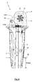
- a pressing tongs 1 according to the invention is shown schematically, here hidden invisible edges are shown in dashed lines. It is possible that the pressing tongs 1 is manufactured in plate construction.
- the pressing tongs 1 has a pliers head 2.
- the pressing tongs are operated by manual operation of hand levers 3, 4, wherein between the hand lever 3, 4 and the pliers head 2 an actuating kinematics 5 is interposed, which is designed as a toggle lever drive 6.
- the pliers head 2 is formed with a base body 7 and an actuating body 8, which are each formed plate-shaped.
- the actuator body 8 is formed as a pivot ring 34.
- the main body 7 is rigidly connected to the hand lever 3, which is why the hand lever 3 is also referred to as a "fixed hand lever".
- the main body 7 and the hand lever 3 are integrally formed in the form of a plate, in particular as a stamped part. Opposite the main body 7 of the actuator body 8 in the plane about a Gesenkachse 9, which is oriented vertically to the plane, rotatable.
- the actuator body 8 has a continuous recess 10 which has a circular contour with radially outwardly extending, uniformly distributed over the circumference grooves 11, whereby a kind of splined shaft profile is formed.
- the actuator body 8 has six such grooves 11. Also distributed uniformly over the circumference of the Gesenkachse 9 here six pivot pins 12, whose longitudinal axes are vertical to the plane Fig. 1 are oriented and which are supported by the base body 7. Opposite the pivot pin 12 are pivotally mounted here six press dies 13 in the plane.
- the pressing dies 13 form a die surface 14 with a radially inwardly bevelled end face.
- the die surfaces 14 of the ram 13 together form a substantially circumferentially around the Gesenkachse 9 closed die 15, whose cross section in the present case corresponds to a hexagon with equal side lengths.
- the cross-sectional area of the die 15 decreases with the pivoting of the ram 13 in a clockwise direction.
- the ram 13 are each receiving in an associated groove 11.
- the grooves 11 form a kind of driver for the ram 13, so that the rotation of the actuator body 8 by the contact of said end portions of the ram 13 with the grooves 11 has the common pivoting of the ram 13 with the same pivot angles result.
- a reduction of the cross-sectional area of the die 15 and thus a pressing of a workpiece arranged in the die 15 take place.
- the pliers head 2 is designed for fundamentally different pressing operations, for example with a different number of press dies, whereby only two press dies or die halves can be present and also one die half of the main body 7 and one die half of the operating body 8 may be formed, which are not rotated in this case relative to each other, but are mutually displaceable in the direction of a pressing stroke.
- the hand lever 4 is hinged in the pliers head 2 facing end portion with a pivot bearing 16 on the actuator body 8.
- the hand lever 4 is for this reason also referred to as a "movable hand lever".
- a pressure lever 18 is hinged to the hand lever 4 in a pivot bearing 17.
- the other end portion of the pressure lever 18 is in a pivot bearing 19 hinged to the hand lever 3.
- the pivot bearing 17 in this case forms a knee joint 25 for a knee lever 20, which is formed by the hand lever 4 in the region between the pivot bearings 16, 17, as well as a toggle lever 21 which is formed by the pressure lever 18.
- the two toggle levers 20, 21 form in the open position according to Fig. 1 an obtuse angle, for example with an angle in the range of 130 °, 140 ° or 150 ° ⁇ 10%, and approach with closing the hand lever 3, 4 of the extended position, see. Fig. 2 ,
- the pressing tongs 1 can be acted upon in the opening direction by means of a return spring 22, whereby an automatic opening of an opening movement is made possible at the end of the total stroke of the pressing tongs 1.
- the return spring 22 acts between the hand levers 3, 4.
- a spring base 23 is supported on the knee joint 25, while the other spring base 24 of the return spring 22 is supported on the hand lever 3, preferably immediately adjacent the pliers head 2 or Actuator 8.
- the return spring 22 is oriented approximately vertically to a longitudinal axis 37 of the hand lever 3.
- the return spring 22 which is designed here as a spiral spring, a rod 26 which is also articulated in the knee joint 25.
- the rod 26 has on its underside a toothing 27. With the toothing 27 of the rod 26 a Zwangsgesperre 28 is formed.
- the Zwangsgesperre 28 has a relative to the hand lever 3 pivotally mounted and acted upon by a spring 29 pawl 30. With closure of the hand lever slides the pawl 30 ratchet-like along the teeth 27 of the rod.
- the pawl 30 secures by engaging the teeth 27 of the rod 26 reached a position of the rod 26 in the Zwangsgesperre 28, whereby the position of the hand lever 3, 4 is secured and the reached closed position of the die 15 is maintained.
- a once achieved pressing stage can be secured. Only with a predetermined end position of the rod 26 in the Zwangsgesperre 28, the blocking effect of Zwangsgesperres 28 by suitable design of the teeth 27 and the pawl 30 is dissolved, whereby at the end of the pressing operation, an opening movement is possible.
- the basic principle of the invention is not necessarily bound to the use of a positive locking mechanism, a return spring and / or the use of the rod 26.
- the pressure lever is formed in both end regions with a thickening, in the region which bearing eyes are formed for the purpose of forming the knee joint 25 and the pivot bearing 19.
- a longitudinal axis 31 a connecting line between the knee joint 25 and the pivot bearing 19 is referred to.
- a center axis 32 designates a shaft which follows the contour of the pressure lever 18 and is curved here.
- the central axis 32 denotes the axis designated in mechanics as a "neutral phase" of the bending lever loaded pressure lever 18 or a geometric cross-sectional central axis.
- the pressure lever 18 has a crank 33. Starting from the toggle 25, the pressure lever 18 is initially formed almost straight or with a small curvature. The curvature increases in the direction of the pivot bearing 19 in increasing extent continuously. For the illustrated embodiment, the pressure lever 18 in rough approximation with the shape of a "hockey stick" is formed, wherein the knee joint 25 is arranged in the region of the "handle” and the pivot bearing 19 in the end region of the "club surface". In view of the offset 33, a force acting along the longitudinal axis 31, which is applied by the hand levers 3, 4 to the pressure lever 18, leads to a stress on the pressure lever 18 on bending. Apart from the aforementioned thickening of the cross section of the pressure lever of the knee joint 25 in the direction of the pivot bearing 19 increases continuously.
- a partial section 35 of the pressure lever is arranged overlapping the hand lever 4.
- the hand lever 4 may be formed with two parallel spaced plates, between these two plates a recess 36 is formed, in which the portion 35 of the hand lever 18 with closure of the hand lever 3, 4 can occur.
- the hand lever 36 in cross-section C-shaped or U-shaped, between the parallel legs of C or U, the recess 36 is formed, which is oriented so that with the closing movement of the section 35 in this recess 36 can occur.
- the entering into the recess 36 portion 35 may well be more than half of the pressure lever 18.
- the curvature of the central axis 32 is such that, at least in the Fig. 1 illustrated opening position, the angle ⁇ of the central axis in the pivot bearing 19 relative to the longitudinal axis 37 of the fixed hand lever 3 is greater than 90 °.
- the course of the pressure lever 18, in particular the curvature of the central axis 32 is such that a maximum distance 38 results between the central axis 32 and the longitudinal axis 31, which is for example at least 1.5 cm, preferably at least 2 cm or at least 2.5 cm ,
- a connecting axis 39 of the Gesenkachse 9 and the pivot bearing 16 forms with a connection axis 43, which connects the free end of the fixed hand lever 3 and whose center with the Gesenkachse 9, an angle ⁇ .
- the angle ⁇ is preferably greater than 50 °, in particular greater than 55 °, 60 ° or 65 °.
- a distance 40 of the die axis 9 from the longitudinal axis 37 is a maximum of less than 8 mm, in particular less than 5 mm or 3 mm.
- the metallic hand lever 3, 4 are taken in the acted upon by the user's hands areas each in a receiving body made of plastic, which are adapted in terms of contour and elasticity to the contact with the user's hands.
- a partial section 35 with the closing movement of the hand lever in a recess 36 of the hand lever 4 (and the receiving body made of plastic) occurs.
- the angle between the connecting axis 39 and a connecting axis of the pivot bearing 16, 19 should be approximately 90 °, at least approaching the closed position of the hand lever 3, 4, said angle also ⁇ 5 °, for example ⁇ 3 °, can deviate from 90 °.
- the pivot bearing 19 is in the lower half of the hand lever, measured from the pliers head 2, is arranged.
- the pivot bearing 19 is at a distance of less than 7 cm, for example, less than 6 cm or a few than 5 cm, from the free end of the hand lever third
- the movement of the pivot bearing 16 during the closing movement of the hand lever is about 5.5 mm.
- the hand span 30 mm from the ends of the hand lever 3, 4 cover a distance of about 80 mm.
- the distance between the pivot bearing 16, 17 is approximately 14.5 mm, while the distance of the pivot bearing 17, 19th preferably 80 mm, with also deviations of ⁇ 20%, for example ⁇ 10% or ⁇ 5% of these dimensions are possible.
Landscapes
- Engineering & Computer Science (AREA)
- Mechanical Engineering (AREA)
- Manufacturing & Machinery (AREA)
- Manufacturing Of Electrical Connectors (AREA)
- Hand Tools For Fitting Together And Separating, Or Other Hand Tools (AREA)
- Sheet Holders (AREA)
Priority Applications (5)
| Application Number | Priority Date | Filing Date | Title |
|---|---|---|---|
| EP14154206.8A EP2905848B1 (fr) | 2014-02-06 | 2014-02-06 | Pince de pression |
| US14/606,362 US9242349B2 (en) | 2014-02-06 | 2015-01-27 | Crimping pliers |
| CN201510040722.4A CN104836092A (zh) | 2014-02-06 | 2015-01-27 | 挤压钳 |
| JP2015022264A JP2015147294A (ja) | 2014-02-06 | 2015-02-06 | 圧着ペンチ |
| HK15110560.2A HK1209909A1 (en) | 2014-02-06 | 2015-10-27 | Crimping pliers |
Applications Claiming Priority (1)
| Application Number | Priority Date | Filing Date | Title |
|---|---|---|---|
| EP14154206.8A EP2905848B1 (fr) | 2014-02-06 | 2014-02-06 | Pince de pression |
Publications (2)
| Publication Number | Publication Date |
|---|---|
| EP2905848A1 true EP2905848A1 (fr) | 2015-08-12 |
| EP2905848B1 EP2905848B1 (fr) | 2016-09-14 |
Family
ID=50068872
Family Applications (1)
| Application Number | Title | Priority Date | Filing Date |
|---|---|---|---|
| EP14154206.8A Not-in-force EP2905848B1 (fr) | 2014-02-06 | 2014-02-06 | Pince de pression |
Country Status (5)
| Country | Link |
|---|---|
| US (1) | US9242349B2 (fr) |
| EP (1) | EP2905848B1 (fr) |
| JP (1) | JP2015147294A (fr) |
| CN (1) | CN104836092A (fr) |
| HK (1) | HK1209909A1 (fr) |
Cited By (5)
| Publication number | Priority date | Publication date | Assignee | Title |
|---|---|---|---|---|
| US9634451B2 (en) | 2014-10-20 | 2017-04-25 | Wezag Gmbh Werkzeugfabrik | Crimping pliers |
| EP3208044A1 (fr) | 2016-02-18 | 2017-08-23 | Wezag GmbH Werkzeugfabrik | Pince comprenant un systeme de levier a genouillere |
| US9864948B2 (en) | 2014-09-11 | 2018-01-09 | Wezag Gmbh Werkzeugfabrik | Hand pliers |
| EP3309915A1 (fr) | 2016-10-14 | 2018-04-18 | Wezag GmbH Werkzeugfabrik | Pince à dénuder, couteau à dénuder, et procédé de dénudage |
| EP3652816A4 (fr) * | 2017-07-11 | 2021-03-10 | Pressmaster AB | Outil à main avec poignée à résilience automatique |
Families Citing this family (17)
| Publication number | Priority date | Publication date | Assignee | Title |
|---|---|---|---|---|
| EP3012924B1 (fr) * | 2014-10-20 | 2017-12-13 | Wezag GmbH Werkzeugfabrik | Pince de pression |
| USD838564S1 (en) * | 2015-03-02 | 2019-01-22 | Phoenix Contact Gmbh & Co. Kg | Tool |
| GB201603923D0 (en) * | 2016-03-07 | 2016-04-20 | Buchanan Nigel | Locking water pump pliers |
| US11541514B2 (en) | 2016-03-23 | 2023-01-03 | Milwaukee Electric Tool Corporation | Locking pliers |
| KR101777241B1 (ko) | 2016-04-19 | 2017-09-11 | 김현민 | 케이블 커넥터 육각 성형 압착기 |
| CN107538548A (zh) * | 2016-06-24 | 2018-01-05 | 万象设计江苏有限责任公司 | 一种用于牛排的快速切块工具 |
| EP3396796B1 (fr) * | 2017-04-25 | 2021-07-21 | WEZAG GmbH & Co. KG | Outil de compression, de sertissage ou de découpe et module d'outils |
| WO2019051491A1 (fr) | 2017-09-11 | 2019-03-14 | Milwaukee Electric Tool Corporation | Pinces de verrouillage à section de mâchoire mobile augmentant le couple |
| CN108896223B (zh) * | 2018-05-02 | 2020-11-10 | 中国工程物理研究院材料研究所 | 一种应力测试装夹装置 |
| TWI668084B (zh) * | 2018-12-28 | 2019-08-11 | 優品企業有限公司 | Steel cable cutter |
| USD910395S1 (en) | 2019-03-11 | 2021-02-16 | Milwaukee Electric Tool Corporation | Pliers |
| JP2021171916A (ja) | 2020-04-28 | 2021-11-01 | ウェザッグ ゲーエムベーハー アンド コー.ケージー | 圧着プライヤダイおよび圧着プライヤ |
| EP3904006B1 (fr) | 2020-04-28 | 2023-06-07 | WEZAG GmbH & Co. KG | Matrice de pince à sertir et pince à sertir |
| AT523722B1 (de) * | 2020-07-21 | 2021-11-15 | Sw Automatisierung Gmbh | Crimpwerkzeug |
| USD1000239S1 (en) * | 2021-06-15 | 2023-10-03 | Cembre S.P.A. | Crimping tool |
| USD963450S1 (en) * | 2021-08-19 | 2022-09-13 | Wenzhou Lisida Tools Co., Ltd | Crimping tool |
| USD963451S1 (en) * | 2021-08-19 | 2022-09-13 | Wenzhou Lisida Tools Co., Ltd | Crimping tool |
Citations (11)
| Publication number | Priority date | Publication date | Assignee | Title |
|---|---|---|---|---|
| GB2072081A (en) * | 1980-03-19 | 1981-09-30 | Toolema Ab | Tool having two working jaws particularly for use in crimping |
| EP0158611B1 (fr) | 1984-02-27 | 1990-07-04 | Pressmaster Tool Ab | Outil de sertissage |
| US5408904A (en) * | 1993-07-07 | 1995-04-25 | Neff; Ted | Quick-adjustable and locking tool |
| WO1995023048A1 (fr) | 1994-02-25 | 1995-08-31 | Pressmaster Tool Ab | Agencement d'outil |
| DE19507347C1 (de) * | 1995-03-02 | 1996-09-12 | Rennsteig Werkzeuge Gmbh | Preßzange für Aderendhülsen |
| DE19709639A1 (de) * | 1997-03-08 | 1998-09-10 | Wezag Gmbh | Zange zum Verpressen von Fassungen, Rohren, Kabelschuhen u. dgl. |
| DE19858719A1 (de) * | 1998-12-18 | 2000-06-21 | Connectool Gmbh & Co | Preßwerkzeug |
| DE10140270B4 (de) | 2001-08-16 | 2004-09-30 | Wezag Gmbh Werkzeugfabrik | Presszange zum Einpressen mehrerer Kerben auf dem Umfang eines Kontaktelementes |
| DE102005003615B3 (de) | 2005-01-26 | 2006-09-21 | Wezag Gmbh Werkzeugfabrik | Presszange zum Einpressen mehrerer Kerben auf dem Umfang eines Kontaktelementes |
| US7997116B2 (en) | 2006-02-21 | 2011-08-16 | Pressmaster Ab | Link for crimping tool |
| DE102011052967B4 (de) | 2011-08-24 | 2013-12-19 | Wezag Gmbh Werkzeugfabrik | Presszange, Wechselkassette für eine Presszange und Presszangenset |
Family Cites Families (5)
| Publication number | Priority date | Publication date | Assignee | Title |
|---|---|---|---|---|
| US3199335A (en) * | 1962-02-09 | 1965-08-10 | Marion B Holmes | Crimping tool |
| US3713322A (en) * | 1971-01-06 | 1973-01-30 | Deutsch Co Elec Comp | Crimping tool |
| US6889579B1 (en) * | 2004-01-23 | 2005-05-10 | Loggerhead Tools Llc | Adjustable gripping tool |
| TW201008714A (en) * | 2008-07-02 | 2010-03-01 | Rennsteig Werkzeuge Gmbh | Crimping tool |
| DE102009026470A1 (de) * | 2009-05-26 | 2010-12-09 | Rennsteig Werkzeuge Gmbh | Verfahren zur Überwachung des Verschleißes einer Handzange und Vorrichtung hierfür |
-
2014
- 2014-02-06 EP EP14154206.8A patent/EP2905848B1/fr not_active Not-in-force
-
2015
- 2015-01-27 CN CN201510040722.4A patent/CN104836092A/zh active Pending
- 2015-01-27 US US14/606,362 patent/US9242349B2/en not_active Expired - Fee Related
- 2015-02-06 JP JP2015022264A patent/JP2015147294A/ja active Pending
- 2015-10-27 HK HK15110560.2A patent/HK1209909A1/xx unknown
Patent Citations (14)
| Publication number | Priority date | Publication date | Assignee | Title |
|---|---|---|---|---|
| GB2072081A (en) * | 1980-03-19 | 1981-09-30 | Toolema Ab | Tool having two working jaws particularly for use in crimping |
| DE3109289A1 (de) | 1980-03-19 | 1982-01-28 | Toolema AB, 11135 Stockholm | Werkzeug mit zwei arbeitsbacken |
| DE3109289C2 (fr) | 1980-03-19 | 1987-08-06 | C.A. Weidmueller Gmbh & Co, 4930 Detmold, De | |
| EP0158611B1 (fr) | 1984-02-27 | 1990-07-04 | Pressmaster Tool Ab | Outil de sertissage |
| US5408904A (en) * | 1993-07-07 | 1995-04-25 | Neff; Ted | Quick-adjustable and locking tool |
| WO1995023048A1 (fr) | 1994-02-25 | 1995-08-31 | Pressmaster Tool Ab | Agencement d'outil |
| DE19507347C1 (de) * | 1995-03-02 | 1996-09-12 | Rennsteig Werkzeuge Gmbh | Preßzange für Aderendhülsen |
| EP0732779B1 (fr) | 1995-03-02 | 1998-09-30 | Rennsteig Werkzeuge GmbH | Pince pour comprimer des embouts |
| DE19709639A1 (de) * | 1997-03-08 | 1998-09-10 | Wezag Gmbh | Zange zum Verpressen von Fassungen, Rohren, Kabelschuhen u. dgl. |
| DE19858719A1 (de) * | 1998-12-18 | 2000-06-21 | Connectool Gmbh & Co | Preßwerkzeug |
| DE10140270B4 (de) | 2001-08-16 | 2004-09-30 | Wezag Gmbh Werkzeugfabrik | Presszange zum Einpressen mehrerer Kerben auf dem Umfang eines Kontaktelementes |
| DE102005003615B3 (de) | 2005-01-26 | 2006-09-21 | Wezag Gmbh Werkzeugfabrik | Presszange zum Einpressen mehrerer Kerben auf dem Umfang eines Kontaktelementes |
| US7997116B2 (en) | 2006-02-21 | 2011-08-16 | Pressmaster Ab | Link for crimping tool |
| DE102011052967B4 (de) | 2011-08-24 | 2013-12-19 | Wezag Gmbh Werkzeugfabrik | Presszange, Wechselkassette für eine Presszange und Presszangenset |
Cited By (6)
| Publication number | Priority date | Publication date | Assignee | Title |
|---|---|---|---|---|
| US9864948B2 (en) | 2014-09-11 | 2018-01-09 | Wezag Gmbh Werkzeugfabrik | Hand pliers |
| US9634451B2 (en) | 2014-10-20 | 2017-04-25 | Wezag Gmbh Werkzeugfabrik | Crimping pliers |
| EP3208044A1 (fr) | 2016-02-18 | 2017-08-23 | Wezag GmbH Werkzeugfabrik | Pince comprenant un systeme de levier a genouillere |
| EP3309915A1 (fr) | 2016-10-14 | 2018-04-18 | Wezag GmbH Werkzeugfabrik | Pince à dénuder, couteau à dénuder, et procédé de dénudage |
| US10355461B2 (en) | 2016-10-14 | 2019-07-16 | Wezag Gmbh Werkzeugfabrik | Stripping tool and method for stripping |
| EP3652816A4 (fr) * | 2017-07-11 | 2021-03-10 | Pressmaster AB | Outil à main avec poignée à résilience automatique |
Also Published As
| Publication number | Publication date |
|---|---|
| EP2905848B1 (fr) | 2016-09-14 |
| US20150217429A1 (en) | 2015-08-06 |
| US9242349B2 (en) | 2016-01-26 |
| HK1209909A1 (en) | 2016-04-08 |
| JP2015147294A (ja) | 2015-08-20 |
| CN104836092A (zh) | 2015-08-12 |
Similar Documents
| Publication | Publication Date | Title |
|---|---|---|
| EP2905848B1 (fr) | Pince de pression | |
| EP3012923B1 (fr) | Pince de pression | |
| EP3012924B1 (fr) | Pince de pression | |
| EP1941975B1 (fr) | Pince de serrage destinée au serrage d'outils | |
| DE102012107957B3 (de) | Greifkopf, Greifzange und Roboter mit segmentierter Greiffläche zum Ergreifen beliebig geformter Objekte | |
| EP3208044A1 (fr) | Pince comprenant un systeme de levier a genouillere | |
| EP2873122B1 (fr) | Outil de sertissage pour douille d'extrêmité de conducteur | |
| EP2672580B1 (fr) | Tête de pince de sertissage | |
| DE102010037468A1 (de) | Chirurgischer Clip | |
| DE202008003703U1 (de) | Zange mit einem ein zweiteiliges Werkzeug aufweisenden Zangenkopf und einem Positionierer | |
| DE202018006658U1 (de) | Pressbacken, sowie Presszange mit zwei Zangenbacken | |
| EP3718179A1 (fr) | Pince-étau | |
| EP3904007B1 (fr) | Matrice de pince à sertir et pince à sertir | |
| EP3553900A1 (fr) | Mâchoire pivotante de pince du type à plaques et pince de sertissage pourvue de mâchoire pivotante de pince | |
| DE102018121971A1 (de) | Presswerkzeug | |
| EP3834989B1 (fr) | Outil pince à main et procédé de montage d'un tel outil | |
| DE2755482C2 (fr) | ||
| EP3553899A1 (fr) | Outil de sertissage | |
| EP2734316B1 (fr) | Presse manuelle | |
| DE102008007303A1 (de) | Spreizzange | |
| DE102011011511A1 (de) | Crimpwerkzeug mit einer mittels einer Steuerflächeneinrichtung betätigten Crimpbacke | |
| DE102006007107B4 (de) | Rohrschaftzange mit Kraftübersetzung | |
| EP3904006B1 (fr) | Matrice de pince à sertir et pince à sertir | |
| EP3582665B1 (fr) | Dispositif de préhension d'un objet | |
| DE102011083331A1 (de) | Greifinstrument |
Legal Events
| Date | Code | Title | Description |
|---|---|---|---|
| PUAI | Public reference made under article 153(3) epc to a published international application that has entered the european phase |
Free format text: ORIGINAL CODE: 0009012 |
|
| 17P | Request for examination filed |
Effective date: 20140809 |
|
| AK | Designated contracting states |
Kind code of ref document: A1 Designated state(s): AL AT BE BG CH CY CZ DE DK EE ES FI FR GB GR HR HU IE IS IT LI LT LU LV MC MK MT NL NO PL PT RO RS SE SI SK SM TR |
|
| AX | Request for extension of the european patent |
Extension state: BA ME |
|
| GRAP | Despatch of communication of intention to grant a patent |
Free format text: ORIGINAL CODE: EPIDOSNIGR1 |
|
| RIC1 | Information provided on ipc code assigned before grant |
Ipc: B21J 7/16 20060101AFI20150811BHEP Ipc: B25B 7/12 20060101ALI20150811BHEP Ipc: H01R 43/042 20060101ALI20150811BHEP |
|
| INTG | Intention to grant announced |
Effective date: 20150902 |
|
| GRAS | Grant fee paid |
Free format text: ORIGINAL CODE: EPIDOSNIGR3 |
|
| TPAC | Observations filed by third parties |
Free format text: ORIGINAL CODE: EPIDOSNTIPA |
|
| REG | Reference to a national code |
Ref country code: DE Ref legal event code: R079 Ref document number: 502014001423 Country of ref document: DE Free format text: PREVIOUS MAIN CLASS: H01R0043042000 Ipc: B25B0027140000 |
|
| GRAP | Despatch of communication of intention to grant a patent |
Free format text: ORIGINAL CODE: EPIDOSNIGR1 |
|
| RIC1 | Information provided on ipc code assigned before grant |
Ipc: B25B 27/14 20060101AFI20160420BHEP Ipc: B21J 7/16 20060101ALI20160420BHEP Ipc: B25B 7/12 20060101ALI20160420BHEP Ipc: B25B 27/12 20060101ALI20160420BHEP Ipc: B25B 7/16 20060101ALI20160420BHEP Ipc: H01R 43/042 20060101ALI20160420BHEP Ipc: B25B 27/16 20060101ALI20160420BHEP |
|
| INTG | Intention to grant announced |
Effective date: 20160518 |
|
| GRAS | Grant fee paid |
Free format text: ORIGINAL CODE: EPIDOSNIGR3 |
|
| GRAA | (expected) grant |
Free format text: ORIGINAL CODE: 0009210 |
|
| AK | Designated contracting states |
Kind code of ref document: B1 Designated state(s): AL AT BE BG CH CY CZ DE DK EE ES FI FR GB GR HR HU IE IS IT LI LT LU LV MC MK MT NL NO PL PT RO RS SE SI SK SM TR |
|
| REG | Reference to a national code |
Ref country code: GB Ref legal event code: FG4D Free format text: NOT ENGLISH |
|
| REG | Reference to a national code |
Ref country code: CH Ref legal event code: EP |
|
| REG | Reference to a national code |
Ref country code: IE Ref legal event code: FG4D Free format text: LANGUAGE OF EP DOCUMENT: GERMAN |
|
| REG | Reference to a national code |
Ref country code: AT Ref legal event code: REF Ref document number: 828411 Country of ref document: AT Kind code of ref document: T Effective date: 20161015 |
|
| REG | Reference to a national code |
Ref country code: DE Ref legal event code: R096 Ref document number: 502014001423 Country of ref document: DE |
|
| REG | Reference to a national code |
Ref country code: CH Ref legal event code: NV Representative=s name: RIEDERER HASLER AND PARTNER PATENTANWAELTE AG, LI |
|
| REG | Reference to a national code |
Ref country code: SE Ref legal event code: TRGR |
|
| REG | Reference to a national code |
Ref country code: LT Ref legal event code: MG4D |
|
| REG | Reference to a national code |
Ref country code: NL Ref legal event code: MP Effective date: 20160914 |
|
| PG25 | Lapsed in a contracting state [announced via postgrant information from national office to epo] |
Ref country code: LT Free format text: LAPSE BECAUSE OF FAILURE TO SUBMIT A TRANSLATION OF THE DESCRIPTION OR TO PAY THE FEE WITHIN THE PRESCRIBED TIME-LIMIT Effective date: 20160914 Ref country code: RS Free format text: LAPSE BECAUSE OF FAILURE TO SUBMIT A TRANSLATION OF THE DESCRIPTION OR TO PAY THE FEE WITHIN THE PRESCRIBED TIME-LIMIT Effective date: 20160914 Ref country code: NO Free format text: LAPSE BECAUSE OF FAILURE TO SUBMIT A TRANSLATION OF THE DESCRIPTION OR TO PAY THE FEE WITHIN THE PRESCRIBED TIME-LIMIT Effective date: 20161214 Ref country code: HR Free format text: LAPSE BECAUSE OF FAILURE TO SUBMIT A TRANSLATION OF THE DESCRIPTION OR TO PAY THE FEE WITHIN THE PRESCRIBED TIME-LIMIT Effective date: 20160914 Ref country code: FI Free format text: LAPSE BECAUSE OF FAILURE TO SUBMIT A TRANSLATION OF THE DESCRIPTION OR TO PAY THE FEE WITHIN THE PRESCRIBED TIME-LIMIT Effective date: 20160914 |
|
| PG25 | Lapsed in a contracting state [announced via postgrant information from national office to epo] |
Ref country code: NL Free format text: LAPSE BECAUSE OF FAILURE TO SUBMIT A TRANSLATION OF THE DESCRIPTION OR TO PAY THE FEE WITHIN THE PRESCRIBED TIME-LIMIT Effective date: 20160914 Ref country code: LV Free format text: LAPSE BECAUSE OF FAILURE TO SUBMIT A TRANSLATION OF THE DESCRIPTION OR TO PAY THE FEE WITHIN THE PRESCRIBED TIME-LIMIT Effective date: 20160914 Ref country code: GR Free format text: LAPSE BECAUSE OF FAILURE TO SUBMIT A TRANSLATION OF THE DESCRIPTION OR TO PAY THE FEE WITHIN THE PRESCRIBED TIME-LIMIT Effective date: 20161215 |
|
| PG25 | Lapsed in a contracting state [announced via postgrant information from national office to epo] |
Ref country code: EE Free format text: LAPSE BECAUSE OF FAILURE TO SUBMIT A TRANSLATION OF THE DESCRIPTION OR TO PAY THE FEE WITHIN THE PRESCRIBED TIME-LIMIT Effective date: 20160914 Ref country code: RO Free format text: LAPSE BECAUSE OF FAILURE TO SUBMIT A TRANSLATION OF THE DESCRIPTION OR TO PAY THE FEE WITHIN THE PRESCRIBED TIME-LIMIT Effective date: 20160914 |
|
| PG25 | Lapsed in a contracting state [announced via postgrant information from national office to epo] |
Ref country code: CZ Free format text: LAPSE BECAUSE OF FAILURE TO SUBMIT A TRANSLATION OF THE DESCRIPTION OR TO PAY THE FEE WITHIN THE PRESCRIBED TIME-LIMIT Effective date: 20160914 Ref country code: BE Free format text: LAPSE BECAUSE OF NON-PAYMENT OF DUE FEES Effective date: 20170228 Ref country code: ES Free format text: LAPSE BECAUSE OF FAILURE TO SUBMIT A TRANSLATION OF THE DESCRIPTION OR TO PAY THE FEE WITHIN THE PRESCRIBED TIME-LIMIT Effective date: 20160914 Ref country code: SM Free format text: LAPSE BECAUSE OF FAILURE TO SUBMIT A TRANSLATION OF THE DESCRIPTION OR TO PAY THE FEE WITHIN THE PRESCRIBED TIME-LIMIT Effective date: 20160914 Ref country code: IS Free format text: LAPSE BECAUSE OF FAILURE TO SUBMIT A TRANSLATION OF THE DESCRIPTION OR TO PAY THE FEE WITHIN THE PRESCRIBED TIME-LIMIT Effective date: 20170114 Ref country code: SK Free format text: LAPSE BECAUSE OF FAILURE TO SUBMIT A TRANSLATION OF THE DESCRIPTION OR TO PAY THE FEE WITHIN THE PRESCRIBED TIME-LIMIT Effective date: 20160914 Ref country code: PT Free format text: LAPSE BECAUSE OF FAILURE TO SUBMIT A TRANSLATION OF THE DESCRIPTION OR TO PAY THE FEE WITHIN THE PRESCRIBED TIME-LIMIT Effective date: 20170116 Ref country code: PL Free format text: LAPSE BECAUSE OF FAILURE TO SUBMIT A TRANSLATION OF THE DESCRIPTION OR TO PAY THE FEE WITHIN THE PRESCRIBED TIME-LIMIT Effective date: 20160914 Ref country code: BG Free format text: LAPSE BECAUSE OF FAILURE TO SUBMIT A TRANSLATION OF THE DESCRIPTION OR TO PAY THE FEE WITHIN THE PRESCRIBED TIME-LIMIT Effective date: 20161214 |
|
| REG | Reference to a national code |
Ref country code: DE Ref legal event code: R097 Ref document number: 502014001423 Country of ref document: DE |
|
| PG25 | Lapsed in a contracting state [announced via postgrant information from national office to epo] |
Ref country code: IT Free format text: LAPSE BECAUSE OF FAILURE TO SUBMIT A TRANSLATION OF THE DESCRIPTION OR TO PAY THE FEE WITHIN THE PRESCRIBED TIME-LIMIT Effective date: 20160914 |
|
| PLBE | No opposition filed within time limit |
Free format text: ORIGINAL CODE: 0009261 |
|
| STAA | Information on the status of an ep patent application or granted ep patent |
Free format text: STATUS: NO OPPOSITION FILED WITHIN TIME LIMIT |
|
| PG25 | Lapsed in a contracting state [announced via postgrant information from national office to epo] |
Ref country code: DK Free format text: LAPSE BECAUSE OF FAILURE TO SUBMIT A TRANSLATION OF THE DESCRIPTION OR TO PAY THE FEE WITHIN THE PRESCRIBED TIME-LIMIT Effective date: 20160914 |
|
| 26N | No opposition filed |
Effective date: 20170615 |
|
| PG25 | Lapsed in a contracting state [announced via postgrant information from national office to epo] |
Ref country code: MC Free format text: LAPSE BECAUSE OF FAILURE TO SUBMIT A TRANSLATION OF THE DESCRIPTION OR TO PAY THE FEE WITHIN THE PRESCRIBED TIME-LIMIT Effective date: 20160914 |
|
| REG | Reference to a national code |
Ref country code: IE Ref legal event code: MM4A |
|
| PG25 | Lapsed in a contracting state [announced via postgrant information from national office to epo] |
Ref country code: SI Free format text: LAPSE BECAUSE OF FAILURE TO SUBMIT A TRANSLATION OF THE DESCRIPTION OR TO PAY THE FEE WITHIN THE PRESCRIBED TIME-LIMIT Effective date: 20160914 |
|
| REG | Reference to a national code |
Ref country code: FR Ref legal event code: ST Effective date: 20171031 |
|
| PG25 | Lapsed in a contracting state [announced via postgrant information from national office to epo] |
Ref country code: LU Free format text: LAPSE BECAUSE OF NON-PAYMENT OF DUE FEES Effective date: 20170206 |
|
| PG25 | Lapsed in a contracting state [announced via postgrant information from national office to epo] |
Ref country code: FR Free format text: LAPSE BECAUSE OF NON-PAYMENT OF DUE FEES Effective date: 20170228 |
|
| REG | Reference to a national code |
Ref country code: BE Ref legal event code: MM Effective date: 20170228 |
|
| PG25 | Lapsed in a contracting state [announced via postgrant information from national office to epo] |
Ref country code: IE Free format text: LAPSE BECAUSE OF NON-PAYMENT OF DUE FEES Effective date: 20170206 |
|
| PGFP | Annual fee paid to national office [announced via postgrant information from national office to epo] |
Ref country code: CH Payment date: 20180221 Year of fee payment: 5 Ref country code: GB Payment date: 20180221 Year of fee payment: 5 Ref country code: DE Payment date: 20171127 Year of fee payment: 5 |
|
| PGFP | Annual fee paid to national office [announced via postgrant information from national office to epo] |
Ref country code: SE Payment date: 20180222 Year of fee payment: 5 Ref country code: TR Payment date: 20180201 Year of fee payment: 5 |
|
| PG25 | Lapsed in a contracting state [announced via postgrant information from national office to epo] |
Ref country code: MT Free format text: LAPSE BECAUSE OF FAILURE TO SUBMIT A TRANSLATION OF THE DESCRIPTION OR TO PAY THE FEE WITHIN THE PRESCRIBED TIME-LIMIT Effective date: 20160914 |
|
| PG25 | Lapsed in a contracting state [announced via postgrant information from national office to epo] |
Ref country code: AL Free format text: LAPSE BECAUSE OF FAILURE TO SUBMIT A TRANSLATION OF THE DESCRIPTION OR TO PAY THE FEE WITHIN THE PRESCRIBED TIME-LIMIT Effective date: 20160914 |
|
| PG25 | Lapsed in a contracting state [announced via postgrant information from national office to epo] |
Ref country code: HU Free format text: LAPSE BECAUSE OF FAILURE TO SUBMIT A TRANSLATION OF THE DESCRIPTION OR TO PAY THE FEE WITHIN THE PRESCRIBED TIME-LIMIT; INVALID AB INITIO Effective date: 20140206 |
|
| REG | Reference to a national code |
Ref country code: DE Ref legal event code: R119 Ref document number: 502014001423 Country of ref document: DE |
|
| REG | Reference to a national code |
Ref country code: CH Ref legal event code: PL |
|
| REG | Reference to a national code |
Ref country code: SE Ref legal event code: EUG |
|
| GBPC | Gb: european patent ceased through non-payment of renewal fee |
Effective date: 20190206 |
|
| PG25 | Lapsed in a contracting state [announced via postgrant information from national office to epo] |
Ref country code: CY Free format text: LAPSE BECAUSE OF FAILURE TO SUBMIT A TRANSLATION OF THE DESCRIPTION OR TO PAY THE FEE WITHIN THE PRESCRIBED TIME-LIMIT Effective date: 20160914 Ref country code: SE Free format text: LAPSE BECAUSE OF NON-PAYMENT OF DUE FEES Effective date: 20190207 |
|
| PG25 | Lapsed in a contracting state [announced via postgrant information from national office to epo] |
Ref country code: MK Free format text: LAPSE BECAUSE OF FAILURE TO SUBMIT A TRANSLATION OF THE DESCRIPTION OR TO PAY THE FEE WITHIN THE PRESCRIBED TIME-LIMIT Effective date: 20160914 |
|
| PG25 | Lapsed in a contracting state [announced via postgrant information from national office to epo] |
Ref country code: CH Free format text: LAPSE BECAUSE OF NON-PAYMENT OF DUE FEES Effective date: 20190228 Ref country code: LI Free format text: LAPSE BECAUSE OF NON-PAYMENT OF DUE FEES Effective date: 20190228 |
|
| PG25 | Lapsed in a contracting state [announced via postgrant information from national office to epo] |
Ref country code: GB Free format text: LAPSE BECAUSE OF NON-PAYMENT OF DUE FEES Effective date: 20190206 Ref country code: DE Free format text: LAPSE BECAUSE OF NON-PAYMENT OF DUE FEES Effective date: 20190903 |
|
| REG | Reference to a national code |
Ref country code: AT Ref legal event code: MM01 Ref document number: 828411 Country of ref document: AT Kind code of ref document: T Effective date: 20190206 |
|
| PG25 | Lapsed in a contracting state [announced via postgrant information from national office to epo] |
Ref country code: AT Free format text: LAPSE BECAUSE OF NON-PAYMENT OF DUE FEES Effective date: 20190206 |
|
| PG25 | Lapsed in a contracting state [announced via postgrant information from national office to epo] |
Ref country code: TR Free format text: LAPSE BECAUSE OF NON-PAYMENT OF DUE FEES Effective date: 20190206 |