EP2904164B1 - Abdeckung - Google Patents
Abdeckung Download PDFInfo
- Publication number
- EP2904164B1 EP2904164B1 EP13758880.2A EP13758880A EP2904164B1 EP 2904164 B1 EP2904164 B1 EP 2904164B1 EP 13758880 A EP13758880 A EP 13758880A EP 2904164 B1 EP2904164 B1 EP 2904164B1
- Authority
- EP
- European Patent Office
- Prior art keywords
- lateral faces
- locking elements
- cover
- sections
- spring sections
- Prior art date
- Legal status (The legal status is an assumption and is not a legal conclusion. Google has not performed a legal analysis and makes no representation as to the accuracy of the status listed.)
- Active
Links
Images

Classifications
-
- E—FIXED CONSTRUCTIONS
- E03—WATER SUPPLY; SEWERAGE
- E03F—SEWERS; CESSPOOLS
- E03F5/00—Sewerage structures
- E03F5/04—Gullies inlets, road sinks, floor drains with or without odour seals or sediment traps
- E03F5/06—Gully gratings
-
- E—FIXED CONSTRUCTIONS
- E03—WATER SUPPLY; SEWERAGE
- E03F—SEWERS; CESSPOOLS
- E03F5/00—Sewerage structures
- E03F5/04—Gullies inlets, road sinks, floor drains with or without odour seals or sediment traps
- E03F5/06—Gully gratings
- E03F2005/065—Gully gratings with elastic locking elements
Definitions
- the invention relates to a cover according to the preamble of claim 1.
- Covers for a bottom-mountable open-topped hollow body e.g. a shaft or a drain body, in particular for a drainage channel
- a bottom-mountable open-topped hollow body e.g. a shaft or a drain body, in particular for a drainage channel
- Important in such covers is a secure hold of the cover against the hollow body, even if the cover is run over at a higher speed, which brings a pulse-shaped dynamic load with it. By such loads namely deform the covers and "jump" so to speak upwards.
- loads namely deform the covers and "jump" so to speak upwards.
- how laborious is the method of manufacture of the cover. Namely, such covers are installed in a wide variety, so that the manufacturing costs and also the installation costs are quite a noteworthy factor.
- the previously known simple locking elements are often connected in a complex manner with side walls of the cover and formed as a resilient body which press against inner surfaces of the hollow body and engage in there provided recesses.
- the known arrangements are too complicated to manufacture.
- the invention is based on the object to develop a cover of the type mentioned in that in a simple manner a permanently functional safety, in particular a satisfactory contact pressure with little effort is achieved.
- this object is achieved by a cover for a built-in a bottom, open-topped hollow body, namely a shaft or drain body, in particular for a drainage channel, comprising side walls on which locking elements are protruding from the side cheeks mounted such that the locking elements resiliently on inner surfaces of Hollow body can be pressed, achieved in that the side cheeks adjacent to the locking elements have spring portions such that the locking elements are easier to move toward each other than the side cheeks.
- the locking elements are arranged between the upper edges and lower edges of the side cheeks, so stand out not further.
- increased security against injury of the locking elements is guaranteed.
- the lower edges of the side cheeks are smooth throughout.
- the side cheeks are inventively designed to form the spring sections diluted. It can therefore be ensured by simply reducing the material thickness in sections, an increased spring action.
- the side cheeks are designed to form the spring sections with wave-shaped sections. This results in areas which are variable in length, so that the adjacent, non-curved (and thicker) portions of the side cheeks do not have to yield when bending the locking elements.
- the side cheeks are formed with the exception of the spring portions with a substantially constant thickness, so that a high stability can be ensured.
- the cover is preferably formed from plastic, but in particular formed as an injection molded part. Thus, the cover can be produced in a simple manner.
- a cover 10 is provided, the support edges 13, 14 which are connected by transverse webs 15 (with drainage slots lying therebetween).
- Locking elements 30, 30 ' are provided, which either in recesses 3, 3' of the hollow body 1 advertise (see Fig. 1 ) or on inner surfaces 2, 2 'of the hollow body 1 (see Fig. 2 ) are pressed. These locking elements 30, 30 'each have a nose 33, which include a steep upper inclined surface 31 and a less steep lower inclined surface 32.
- the locking elements 30, 30 'in the region of side cheeks 20, 20' are provided, the Go over the upper edges 23 in the support edges 13, 14. Bottom edges 24 of the side cheeks 20, 20 'are smooth continuous, formed substantially without protruding parts.
- spring sections 21, 22 are provided in the side cheeks 20, 20'. These spring sections are formed in this embodiment of the invention as a simple material dilutions of the side cheeks 20, 20 'such that a waveform is formed.
Landscapes
- Health & Medical Sciences (AREA)
- Life Sciences & Earth Sciences (AREA)
- Engineering & Computer Science (AREA)
- Hydrology & Water Resources (AREA)
- Public Health (AREA)
- Water Supply & Treatment (AREA)
- Sink And Installation For Waste Water (AREA)
Description
- Die Erfindung betrifft eine Abdeckung nach dem Oberbegriff des Patentanspruches 1.
- Abdeckungen für einen in einen Boden einbaubaren oben offenen Hohlkörper, z.B. einen Schacht oder einen Abflusskörper, insbesondere für eine Entwässerungsrinne, sind in verschiedensten Ausführungsformen bekannt. Wichtig bei derartigen Abdeckungen ist ein sicherer Halt der Abdeckung gegenüber dem Hohlkörper auch dann, wenn die Abdeckung mit höherer Geschwindigkeit überfahren wird, was eine impulsförmige, dynamische Belastung mit sich bringt. Durch derartige Belastungen verformen sich nämlich die Abdeckungen und "springen" sozusagen nach oben. Neben einem solchen sicheren Halt ist aber noch von erheblicher Bedeutung, wie aufwändig die Herstellungsweise der Abdeckung ist. Derartige Abdeckungen werden nämlich in einer großen Vielzahl verbaut, so dass die Herstellungskosten und auch die Montagekosten einen durchaus beachtenswerten Faktor darstellen.
- Die bisher bekannten einfachen Verriegelungselemente sind oftmals in aufwändiger Weise mit Seitenwangen der Abdeckung verbunden und als federelastische Körper ausgebildet, die gegen Innenflächen des Hohlkörpers drücken bzw. in dort vorgesehene Ausnehmungen einrasten. Die bekannten Anordnungen sind zu aufwändig in der Herstellung.
- Insbesondere ist aus
FR 2 740 789 A1 DE 10 2010 036 509 A1 bekannt. - Der Erfindung liegt die Aufgabe zu Grunde, eine Abdeckung der eingangs genannten Art dahingehend weiterzubilden, dass in einfacher Weise eine dauerhaft funktionelle Sicherheit, insbesondere eine zufriedenstellende Anpresskraft mit geringem Aufwand erzielbar ist.
- Diese Aufgabe wird durch eine Abdeckung nach Anspruch 1 gelöst.
- Insbesondere wird diese Aufgabe durch eine Abdeckung für einen in einen Boden einbaubaren, oben offenen Hohlkörper, nämlich einen Schacht oder Abflusskörper, insbesondere für eine Entwässerungsrinne, umfassend Seitenwangen, an denen Verriegelungselemente von den Seitenwangen hervorstehend derart angebracht sind, dass die Verriegelungselemente federelastisch an Innenflächen des Hohlkörpers anpressbar sind, dadurch gelöst, dass die Seitenwangen benachbart zu den Verriegelungselementen Federabschnitte derart aufweisen, dass die Verriegelungselemente leichter aufeinander zu bewegbar sind als die Seitenwangen.
- Dies bedeutet, dass die Seitenwangen selbst die Federabschnitte bilden, wobei in den Bereichen außerhalb der Verriegelungselemente die Seitenwangen mit ihrer "normalen" Steifigkeit ausgebildet sind, was für die Gesamtstabilität der Abdeckung von Vorteil ist. Andererseits werden aber keine zusätzlichen Federelemente benötigt, um die Verriegelungselemente federelastisch auszubilden. Dies bedeutet eine erhebliche Ersparnis bei der Herstellung.
- Die Verriegelungselemente sind zwischen Oberrändern und Unterrändern der Seitenwangen angeordnet, stehen also nicht weiter hervor. Dadurch wird neben einer verbesserten Stapelbarkeit der Abdeckung (diese ist für die Lagerhaltung und den Transport sehr wichtig) eine erhöhte Sicherheit gegenüber Verletzungen der Riegelelemente (ggf. auch Verletzungen des Einbaupersonals durch die Verriegelungselemente) gewährleistet. Die Unterränder der Seitenwangen sind glatt durchgehend ausgebildet.
- Die Seitenwangen sind erfindungsgemäss zur Bildung der Federabschnitte verdünnt ausgebildet. Es kann also ganz einfach durch abschnittsweise Verringerung der Materialstärke eine erhöhte Federwirkung sichergestellt werden.
- Hierzu werden erfindungsgemäss die Seitenwangen zur Bildung der Federabschnitte mit wellenförmigen Abschnitten ausgebildet. Dadurch ergeben sich Bereiche, die in ihrer Länge variierbar sind, so dass die benachbarten, nicht gekrümmten (und dicker ausgebildeten) Abschnitte der Seitenwangen beim Verbiegen der Verriegelungselemente nicht nachgeben müssen.
- Vorzugsweise sind die Seitenwangen bis auf die Federabschnitte mit im Wesentlichen konstanter Dicke ausgebildet, so dass eine hohe Stabilität gewährleistet werden kann.
Die Abdeckung ist vorzugsweise aus Kunststoff geformt, insbesondere aber als Spritzgussteil ausgebildet. Damit wird die Abdeckung in einfacher Weise herstellbar. - Nachfolgend wird eine bevorzugte Ausführungsform der Erfindung anhand von Abbildungen näher erläutert. Hierbei zeigen
- Fig. 1
- einen schematisierten Querschnitt durch eine Abdeckung mit darunter liegender Rinne,
- Fig. 2
- eine zweite Ausführungsform der Erfindung mit einer Rinne ohne Hinterschneidung,
- Fig. 3
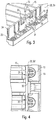
- eine perspektivische Unteransicht auf einen Abschnitt der Abdeckung, und
- Fig. 4
- eine Teil-Draufsicht auf eine Unterseite der Abdeckung nach den
Fig. 1-3 . - In der nachfolgenden Beschreibung werden für gleiche und gleich wirkende Teile dieselben Bezugsziffern verwendet.
- Wie aus den
Fig. 1 und 2 hervorgeht, ist eine Abdeckung 10 vorgesehen, die Auflageränder 13, 14 aufweist, welche über Querstege 15 (mit dazwischen liegenden Entwässerungsschlitzen) verbunden sind. - Verriegelungselemente 30, 30' sind vorgesehen, welche entweder in Ausnehmungen 3, 3' des Hohlkörpers 1 inserieren (siehe
Fig. 1 ) oder an Innenflächen 2, 2' der Hohlkörper 1 (sieheFig. 2 ) angepresst sind. Diese Verriegelungselemente 30, 30' weisen jeweils eine Nase 33 auf, die eine steile obere Schrägfläche 31 und eine weniger steile untere Schrägfläche 32 umfassen. - Wie insbesondere aus den
Fig. 3 und 4 hervorgeht, sind die Verriegelungselemente 30, 30' im Bereich von Seitenwangen 20, 20' vorgesehen, deren Oberränder 23 in die Auflagenränder 13, 14 übergehen. Unterränder 24 der Seitenwangen 20, 20' sind glatt durchgehend, im Wesentlichen ohne hervorspringende Teile ausgebildet.
Um die Verriegelungselemente 30, 30' mit einer Elastizität derart auszubilden, dass die Nasen 33 nach innen gedrückt werden können, sind in den Seitenwangen 20, 20' Federabschnitte 21, 22 vorgesehen. Diese Federabschnitte sind bei dieser Ausführungsform der Erfindung als einfache Materialverdünnungen der Seitenwangen 20, 20' derart ausgebildet, dass eine Wellenform entsteht. Es sind also an den Außenseiten der Seitenwangen 20, 20' zwei Zylinder-abschnittsförmige Materialausnehmungen und auf der Innenseite der Seitenwangen 20, 20' eine ebenso Zylinder-abschnittsförmige Ausnehmung dazwischen ausgebildet, so dass in der Draufsicht eine Wellenform entsteht. Es wird also durch eine geschickte Materialreduzierung erreicht, dass bei einer Beaufschlagung der Verriegelungselemente 30, 30' bzw. der Nase 33 mit einer von außen nach innen wirkenden Kraft die Federabschnitte 21, 22 nachgeben können, ohne dass dadurch die Seitenwangen 20, 20' verformt werden müssten. Dies bedeutet, dass die Seitenwangen 20, 20' stabil ausgebildet werden können, was die Tragkraft der Abdeckung 10 erhöht, ohne dass dadurch die Steifigkeit der Verriegelungselemente 30, 30' erhöht würde. -
- 1
- Hohlkörper
- 2, 2'
- Innenfläche
- 3, 3'
- Ausnehmung
- 10
- Abdeckung
- 13
- Auflagerand
- 14
- Auflagerand
- 15
- Quersteg
- 20, 20'
- Seitenwange
- 21
- Federabschnitt
- 22
- Federabschnitt
- 23
- Oberrand
- 24
- Unterrand
- 30, 30'
- Verriegelungselement
- 31
- Obere Schrägfläche
- 32
- Untere Schrägfläche
- 33
- Nase
Claims (4)
- Abdeckung für einen in einen Boden einbaubaren, oben offenen Hohlkörper (10), nämlich einen Schacht oder Abflusskörper, insbesondere für eine Entwässerungsrinne, umfassend Seitenwangen (20, 20'), an denen Verriegelungselemente (30, 30') von den Seitenwangen (20, 20') hervorstehend derart angebracht sind, dass die Verriegelungselemente (30, 30') federelastisch an Innenflächen (2, 2') des Hohlkörpers (1) anpressbar oder in Ausnehmungen (3, 3') des Hohlkörpers (1) einpressbar sind, wobei
die Verriegelungselemente (30, 30') zwischen Oberrändern (23) und Unterrändern (24) der Seitenwangen (20, 20') angeordnet sind, wobei die Seitenwangen (20, 20') benachbart zu den Verriegelungselementen (30, 30') Federabschnitte (21, 22) derart aufweisen, dass die Verriegelungselemente (30, 30') leichter aufeinander zu bewegbar sind als die Seitenwangen (20, 20'), wobei die Seitenwangen (20, 20') zur Bildung der Federabschnitte (21, 22) verdünnt ausgebildet sind und wellenförmig gekrümmte Abschnitte aufweisen, wobei benachbarte, nicht gekrümmte Abschnitte der Seitenwangen (20, 20') dicker als die Federabschnitte (21, 22) und nicht nachgebend ausgebildet sind,
dadurch gekennzeichnet, dass
an den Außenseiten der Seitenwangen (20, 20') zwei Zylinder-abschnittsförmige Materialausnehmungen ausgebildet sind und auf der Innenseite der Seitenwangen (20, 20') eine Zylinder-abschnittsförmige Ausnehmung dazwischen ausgebildet ist, sodass in der Draufsicht eine Wellenform zur Bildung der Federabschnitte (21, 22) entsteht. - Abdeckung nach Anspruch 1,
dadurch gekennzeichnet, dass Unterränder (24) der Seitenwangen (20, 20') glatt durchgehend ausgebildet sind. - Abdeckung nach einem der vorhergehenden Ansprüche,
dadurch gekennzeichnet, dass die Seitenwangen (20, 20') bis auf die Federabschnitte (21, 22) mit konstanter Dicke ausgebildet sind. - Abdeckung nach einem der vorhergehenden Ansprüche,
dadurch gekennzeichnet, dass die Abdeckung aus Kunststoff geformt, insbesondere als Spritzgussteil ausgebildet ist.
Priority Applications (1)
| Application Number | Priority Date | Filing Date | Title |
|---|---|---|---|
| PL13758880T PL2904164T3 (pl) | 2012-09-10 | 2013-09-06 | Pokrywa |
Applications Claiming Priority (2)
| Application Number | Priority Date | Filing Date | Title |
|---|---|---|---|
| DE102012108408.4A DE102012108408A1 (de) | 2012-09-10 | 2012-09-10 | Abdeckung |
| PCT/EP2013/068424 WO2014037477A1 (de) | 2012-09-10 | 2013-09-06 | Abdeckung |
Publications (2)
| Publication Number | Publication Date |
|---|---|
| EP2904164A1 EP2904164A1 (de) | 2015-08-12 |
| EP2904164B1 true EP2904164B1 (de) | 2019-04-17 |
Family
ID=49117861
Family Applications (1)
| Application Number | Title | Priority Date | Filing Date |
|---|---|---|---|
| EP13758880.2A Active EP2904164B1 (de) | 2012-09-10 | 2013-09-06 | Abdeckung |
Country Status (5)
| Country | Link |
|---|---|
| EP (1) | EP2904164B1 (de) |
| DE (1) | DE102012108408A1 (de) |
| DK (1) | DK2904164T3 (de) |
| PL (1) | PL2904164T3 (de) |
| WO (1) | WO2014037477A1 (de) |
Families Citing this family (1)
| Publication number | Priority date | Publication date | Assignee | Title |
|---|---|---|---|---|
| CN111321662B (zh) * | 2020-03-13 | 2021-06-18 | 吴晓雯 | 一种道路桥梁施工路面排水系统 |
Family Cites Families (7)
| Publication number | Priority date | Publication date | Assignee | Title |
|---|---|---|---|---|
| FR2740789B1 (fr) * | 1995-11-03 | 1998-01-30 | Prefaest Sa | Caniveau et grille pour caniveau |
| CH693098A5 (de) * | 1999-02-25 | 2003-02-28 | Von Roll Holding Ag | Einrichtung zum Abdecken einer Bodenöffnung |
| DE20307802U1 (de) * | 2003-05-20 | 2003-09-25 | Hauraton Betonwarenfabrik GmbH & Co. KG, 76437 Rastatt | Kunststoffrinne |
| DE10328612B4 (de) * | 2003-06-25 | 2009-04-09 | Aco Severin Ahlmann Gmbh & Co. Kg | Oberflächenentwässerungseinrichtung |
| ITPN20040059A1 (it) * | 2004-08-16 | 2004-11-16 | Gridiron Spa | Griglia per canale di drenaggio |
| DE102010017424A1 (de) * | 2010-06-17 | 2011-12-22 | Aco Severin Ahlmann Gmbh & Co. Kg | Vorrichtung zum Verriegeln einer Abdeckung |
| DE102010036509A1 (de) * | 2010-07-20 | 2012-01-26 | Aco Severin Ahlmann Gmbh & Co. Kg | Vorrichtung zum Arretieren einer Abdeckung auf einer Entwässerungsrinne oder dergleichen Entwässerungselement |
-
2012
- 2012-09-10 DE DE102012108408.4A patent/DE102012108408A1/de not_active Withdrawn
-
2013
- 2013-09-06 PL PL13758880T patent/PL2904164T3/pl unknown
- 2013-09-06 WO PCT/EP2013/068424 patent/WO2014037477A1/de not_active Ceased
- 2013-09-06 DK DK13758880.2T patent/DK2904164T3/da active
- 2013-09-06 EP EP13758880.2A patent/EP2904164B1/de active Active
Non-Patent Citations (1)
| Title |
|---|
| None * |
Also Published As
| Publication number | Publication date |
|---|---|
| EP2904164A1 (de) | 2015-08-12 |
| WO2014037477A1 (de) | 2014-03-13 |
| DK2904164T3 (da) | 2019-07-08 |
| PL2904164T3 (pl) | 2019-09-30 |
| DE102012108408A1 (de) | 2014-04-03 |
Similar Documents
| Publication | Publication Date | Title |
|---|---|---|
| EP2679522B1 (de) | Transportbandelement zum Transportieren von Gütern, Verfahren zum Führen eines Transportbandelements und Anordnung aus einem Transportbandelement und einer Umlenk- und/oder Antriebswalzenvorrichtung | |
| DE60105680T2 (de) | Rolle für Kette und mit der Rolle versehene Kette | |
| EP3147239B1 (de) | Zahnriemen mit integrierten stützrollen | |
| DE2737181A1 (de) | Foerderer | |
| EP2809006A1 (de) | Bedienelement | |
| DE102008034922B4 (de) | Wälzlagerkäfig | |
| WO2014095733A1 (de) | Wälzlager | |
| DE102005034739A1 (de) | Lagerung eines schwenkbaren Hebels | |
| WO2021069008A1 (de) | Zweiteiliger lagerkäfig sowie wälzlager mit einem solchen lagerkäfig | |
| DE202013001888U1 (de) | Walze zum Führen einer Flachbahn | |
| EP3586024B1 (de) | Rollbalg mit mindestens einer versteifungsrippe | |
| EP3074335B1 (de) | Handlaufantrieb für eine fahrtreppe oder einen fahrsteig | |
| DE102009053090A1 (de) | Käfig für Kegelrollen und Verfahren zu dessen Herstellung | |
| EP3131835B1 (de) | Mülltonne mit einem spritzgegossenen kunststoffkörper | |
| EP2110194A2 (de) | Sägeblatt und Handsäge | |
| DE102012108408A1 (de) | Abdeckung | |
| DE202006016652U1 (de) | Längsverstellvorrichtung für einen Kraftfahrzeugsitz | |
| DE29802228U1 (de) | Lagerschild | |
| EP3041385A1 (de) | Laufrolle | |
| EP1091903A1 (de) | Handlaufführung einer rolltreppe oder eines rollsteiges | |
| EP1449958B1 (de) | Vorrichtung zur Behandlung insbesondere zur Unterdruck-Beaufschlagung, des in einer Anlage zur Papiererzeugung vorgesehenen im Umlauf bewgten mindestens einen Siebbandes bzw. Filzbandes | |
| DE102007036107A1 (de) | Wälzlagerkäfig und Verfahren zum Herstellen eines Wälzlagerkäfigs | |
| DE2302602C3 (de) | Handlauf für Rolltreppen | |
| AT515082B1 (de) | Fußabstreifmatte | |
| EP2904165B1 (de) | Kombination einer entwässerungsrinne mit einer abdeckung |
Legal Events
| Date | Code | Title | Description |
|---|---|---|---|
| PUAI | Public reference made under article 153(3) epc to a published international application that has entered the european phase |
Free format text: ORIGINAL CODE: 0009012 |
|
| 17P | Request for examination filed |
Effective date: 20150331 |
|
| AK | Designated contracting states |
Kind code of ref document: A1 Designated state(s): AL AT BE BG CH CY CZ DE DK EE ES FI FR GB GR HR HU IE IS IT LI LT LU LV MC MK MT NL NO PL PT RO RS SE SI SK SM TR |
|
| AX | Request for extension of the european patent |
Extension state: BA ME |
|
| RIN1 | Information on inventor provided before grant (corrected) |
Inventor name: AHLMANN, IVER Inventor name: MEIER, STEPHAN Inventor name: MIEZE, JAN |
|
| DAX | Request for extension of the european patent (deleted) | ||
| STAA | Information on the status of an ep patent application or granted ep patent |
Free format text: STATUS: EXAMINATION IS IN PROGRESS |
|
| 17Q | First examination report despatched |
Effective date: 20161222 |
|
| GRAP | Despatch of communication of intention to grant a patent |
Free format text: ORIGINAL CODE: EPIDOSNIGR1 |
|
| STAA | Information on the status of an ep patent application or granted ep patent |
Free format text: STATUS: GRANT OF PATENT IS INTENDED |
|
| INTG | Intention to grant announced |
Effective date: 20180524 |
|
| GRAJ | Information related to disapproval of communication of intention to grant by the applicant or resumption of examination proceedings by the epo deleted |
Free format text: ORIGINAL CODE: EPIDOSDIGR1 |
|
| STAA | Information on the status of an ep patent application or granted ep patent |
Free format text: STATUS: EXAMINATION IS IN PROGRESS |
|
| GRAS | Grant fee paid |
Free format text: ORIGINAL CODE: EPIDOSNIGR3 |
|
| STAA | Information on the status of an ep patent application or granted ep patent |
Free format text: STATUS: GRANT OF PATENT IS INTENDED |
|
| GRAP | Despatch of communication of intention to grant a patent |
Free format text: ORIGINAL CODE: EPIDOSNIGR1 |
|
| INTC | Intention to grant announced (deleted) | ||
| INTG | Intention to grant announced |
Effective date: 20181031 |
|
| GRAA | (expected) grant |
Free format text: ORIGINAL CODE: 0009210 |
|
| STAA | Information on the status of an ep patent application or granted ep patent |
Free format text: STATUS: THE PATENT HAS BEEN GRANTED |
|
| AK | Designated contracting states |
Kind code of ref document: B1 Designated state(s): AL AT BE BG CH CY CZ DE DK EE ES FI FR GB GR HR HU IE IS IT LI LT LU LV MC MK MT NL NO PL PT RO RS SE SI SK SM TR |
|
| REG | Reference to a national code |
Ref country code: GB Ref legal event code: FG4D Free format text: NOT ENGLISH |
|
| REG | Reference to a national code |
Ref country code: CH Ref legal event code: EP |
|
| REG | Reference to a national code |
Ref country code: DE Ref legal event code: R096 Ref document number: 502013012661 Country of ref document: DE |
|
| REG | Reference to a national code |
Ref country code: AT Ref legal event code: REF Ref document number: 1121706 Country of ref document: AT Kind code of ref document: T Effective date: 20190515 Ref country code: IE Ref legal event code: FG4D Free format text: LANGUAGE OF EP DOCUMENT: GERMAN |
|
| REG | Reference to a national code |
Ref country code: DK Ref legal event code: T3 Effective date: 20190704 |
|
| REG | Reference to a national code |
Ref country code: NL Ref legal event code: FP |
|
| REG | Reference to a national code |
Ref country code: SE Ref legal event code: TRGR |
|
| REG | Reference to a national code |
Ref country code: LT Ref legal event code: MG4D |
|
| PG25 | Lapsed in a contracting state [announced via postgrant information from national office to epo] |
Ref country code: LT Free format text: LAPSE BECAUSE OF FAILURE TO SUBMIT A TRANSLATION OF THE DESCRIPTION OR TO PAY THE FEE WITHIN THE PRESCRIBED TIME-LIMIT Effective date: 20190417 Ref country code: ES Free format text: LAPSE BECAUSE OF FAILURE TO SUBMIT A TRANSLATION OF THE DESCRIPTION OR TO PAY THE FEE WITHIN THE PRESCRIBED TIME-LIMIT Effective date: 20190417 Ref country code: FI Free format text: LAPSE BECAUSE OF FAILURE TO SUBMIT A TRANSLATION OF THE DESCRIPTION OR TO PAY THE FEE WITHIN THE PRESCRIBED TIME-LIMIT Effective date: 20190417 Ref country code: AL Free format text: LAPSE BECAUSE OF FAILURE TO SUBMIT A TRANSLATION OF THE DESCRIPTION OR TO PAY THE FEE WITHIN THE PRESCRIBED TIME-LIMIT Effective date: 20190417 Ref country code: NO Free format text: LAPSE BECAUSE OF FAILURE TO SUBMIT A TRANSLATION OF THE DESCRIPTION OR TO PAY THE FEE WITHIN THE PRESCRIBED TIME-LIMIT Effective date: 20190717 Ref country code: PT Free format text: LAPSE BECAUSE OF FAILURE TO SUBMIT A TRANSLATION OF THE DESCRIPTION OR TO PAY THE FEE WITHIN THE PRESCRIBED TIME-LIMIT Effective date: 20190817 Ref country code: HR Free format text: LAPSE BECAUSE OF FAILURE TO SUBMIT A TRANSLATION OF THE DESCRIPTION OR TO PAY THE FEE WITHIN THE PRESCRIBED TIME-LIMIT Effective date: 20190417 |
|
| PG25 | Lapsed in a contracting state [announced via postgrant information from national office to epo] |
Ref country code: GR Free format text: LAPSE BECAUSE OF FAILURE TO SUBMIT A TRANSLATION OF THE DESCRIPTION OR TO PAY THE FEE WITHIN THE PRESCRIBED TIME-LIMIT Effective date: 20190718 Ref country code: LV Free format text: LAPSE BECAUSE OF FAILURE TO SUBMIT A TRANSLATION OF THE DESCRIPTION OR TO PAY THE FEE WITHIN THE PRESCRIBED TIME-LIMIT Effective date: 20190417 Ref country code: BG Free format text: LAPSE BECAUSE OF FAILURE TO SUBMIT A TRANSLATION OF THE DESCRIPTION OR TO PAY THE FEE WITHIN THE PRESCRIBED TIME-LIMIT Effective date: 20190717 Ref country code: RS Free format text: LAPSE BECAUSE OF FAILURE TO SUBMIT A TRANSLATION OF THE DESCRIPTION OR TO PAY THE FEE WITHIN THE PRESCRIBED TIME-LIMIT Effective date: 20190417 |
|
| PG25 | Lapsed in a contracting state [announced via postgrant information from national office to epo] |
Ref country code: IS Free format text: LAPSE BECAUSE OF FAILURE TO SUBMIT A TRANSLATION OF THE DESCRIPTION OR TO PAY THE FEE WITHIN THE PRESCRIBED TIME-LIMIT Effective date: 20190817 |
|
| REG | Reference to a national code |
Ref country code: DE Ref legal event code: R097 Ref document number: 502013012661 Country of ref document: DE |
|
| PG25 | Lapsed in a contracting state [announced via postgrant information from national office to epo] |
Ref country code: EE Free format text: LAPSE BECAUSE OF FAILURE TO SUBMIT A TRANSLATION OF THE DESCRIPTION OR TO PAY THE FEE WITHIN THE PRESCRIBED TIME-LIMIT Effective date: 20190417 Ref country code: RO Free format text: LAPSE BECAUSE OF FAILURE TO SUBMIT A TRANSLATION OF THE DESCRIPTION OR TO PAY THE FEE WITHIN THE PRESCRIBED TIME-LIMIT Effective date: 20190417 Ref country code: SK Free format text: LAPSE BECAUSE OF FAILURE TO SUBMIT A TRANSLATION OF THE DESCRIPTION OR TO PAY THE FEE WITHIN THE PRESCRIBED TIME-LIMIT Effective date: 20190417 |
|
| PLBE | No opposition filed within time limit |
Free format text: ORIGINAL CODE: 0009261 |
|
| STAA | Information on the status of an ep patent application or granted ep patent |
Free format text: STATUS: NO OPPOSITION FILED WITHIN TIME LIMIT |
|
| PG25 | Lapsed in a contracting state [announced via postgrant information from national office to epo] |
Ref country code: SM Free format text: LAPSE BECAUSE OF FAILURE TO SUBMIT A TRANSLATION OF THE DESCRIPTION OR TO PAY THE FEE WITHIN THE PRESCRIBED TIME-LIMIT Effective date: 20190417 |
|
| 26N | No opposition filed |
Effective date: 20200120 |
|
| PG25 | Lapsed in a contracting state [announced via postgrant information from national office to epo] |
Ref country code: TR Free format text: LAPSE BECAUSE OF FAILURE TO SUBMIT A TRANSLATION OF THE DESCRIPTION OR TO PAY THE FEE WITHIN THE PRESCRIBED TIME-LIMIT Effective date: 20190417 |
|
| PG25 | Lapsed in a contracting state [announced via postgrant information from national office to epo] |
Ref country code: MC Free format text: LAPSE BECAUSE OF FAILURE TO SUBMIT A TRANSLATION OF THE DESCRIPTION OR TO PAY THE FEE WITHIN THE PRESCRIBED TIME-LIMIT Effective date: 20190417 Ref country code: SI Free format text: LAPSE BECAUSE OF FAILURE TO SUBMIT A TRANSLATION OF THE DESCRIPTION OR TO PAY THE FEE WITHIN THE PRESCRIBED TIME-LIMIT Effective date: 20190417 |
|
| REG | Reference to a national code |
Ref country code: CH Ref legal event code: PL |
|
| PG25 | Lapsed in a contracting state [announced via postgrant information from national office to epo] |
Ref country code: LU Free format text: LAPSE BECAUSE OF NON-PAYMENT OF DUE FEES Effective date: 20190906 Ref country code: LI Free format text: LAPSE BECAUSE OF NON-PAYMENT OF DUE FEES Effective date: 20190930 Ref country code: IE Free format text: LAPSE BECAUSE OF NON-PAYMENT OF DUE FEES Effective date: 20190906 Ref country code: CH Free format text: LAPSE BECAUSE OF NON-PAYMENT OF DUE FEES Effective date: 20190930 |
|
| PG25 | Lapsed in a contracting state [announced via postgrant information from national office to epo] |
Ref country code: CY Free format text: LAPSE BECAUSE OF FAILURE TO SUBMIT A TRANSLATION OF THE DESCRIPTION OR TO PAY THE FEE WITHIN THE PRESCRIBED TIME-LIMIT Effective date: 20190417 |
|
| PG25 | Lapsed in a contracting state [announced via postgrant information from national office to epo] |
Ref country code: HU Free format text: LAPSE BECAUSE OF FAILURE TO SUBMIT A TRANSLATION OF THE DESCRIPTION OR TO PAY THE FEE WITHIN THE PRESCRIBED TIME-LIMIT; INVALID AB INITIO Effective date: 20130906 Ref country code: MT Free format text: LAPSE BECAUSE OF FAILURE TO SUBMIT A TRANSLATION OF THE DESCRIPTION OR TO PAY THE FEE WITHIN THE PRESCRIBED TIME-LIMIT Effective date: 20190417 |
|
| PG25 | Lapsed in a contracting state [announced via postgrant information from national office to epo] |
Ref country code: MK Free format text: LAPSE BECAUSE OF FAILURE TO SUBMIT A TRANSLATION OF THE DESCRIPTION OR TO PAY THE FEE WITHIN THE PRESCRIBED TIME-LIMIT Effective date: 20190417 |
|
| P01 | Opt-out of the competence of the unified patent court (upc) registered |
Effective date: 20230629 |
|
| PGFP | Annual fee paid to national office [announced via postgrant information from national office to epo] |
Ref country code: NL Payment date: 20230920 Year of fee payment: 11 |
|
| REG | Reference to a national code |
Ref country code: NL Ref legal event code: MM Effective date: 20241001 |
|
| PG25 | Lapsed in a contracting state [announced via postgrant information from national office to epo] |
Ref country code: NL Free format text: LAPSE BECAUSE OF NON-PAYMENT OF DUE FEES Effective date: 20241001 |
|
| PGFP | Annual fee paid to national office [announced via postgrant information from national office to epo] |
Ref country code: DE Payment date: 20250919 Year of fee payment: 13 Ref country code: DK Payment date: 20250922 Year of fee payment: 13 |
|
| PGFP | Annual fee paid to national office [announced via postgrant information from national office to epo] |
Ref country code: PL Payment date: 20250822 Year of fee payment: 13 |
|
| PGFP | Annual fee paid to national office [announced via postgrant information from national office to epo] |
Ref country code: BE Payment date: 20250919 Year of fee payment: 13 Ref country code: GB Payment date: 20250923 Year of fee payment: 13 |
|
| PGFP | Annual fee paid to national office [announced via postgrant information from national office to epo] |
Ref country code: FR Payment date: 20250922 Year of fee payment: 13 Ref country code: AT Payment date: 20250918 Year of fee payment: 13 |
|
| PGFP | Annual fee paid to national office [announced via postgrant information from national office to epo] |
Ref country code: SE Payment date: 20250922 Year of fee payment: 13 |
|
| PGFP | Annual fee paid to national office [announced via postgrant information from national office to epo] |
Ref country code: CZ Payment date: 20250827 Year of fee payment: 13 |
|
| PGFP | Annual fee paid to national office [announced via postgrant information from national office to epo] |
Ref country code: IT Payment date: 20250930 Year of fee payment: 13 |