EP2902690B1 - Détecteur d'anomalie pour canalisations - Google Patents
Détecteur d'anomalie pour canalisations Download PDFInfo
- Publication number
- EP2902690B1 EP2902690B1 EP15152055.8A EP15152055A EP2902690B1 EP 2902690 B1 EP2902690 B1 EP 2902690B1 EP 15152055 A EP15152055 A EP 15152055A EP 2902690 B1 EP2902690 B1 EP 2902690B1
- Authority
- EP
- European Patent Office
- Prior art keywords
- pipeline
- sensor unit
- sensor
- liquid
- ball
- Prior art date
- Legal status (The legal status is an assumption and is not a legal conclusion. Google has not performed a legal analysis and makes no representation as to the accuracy of the status listed.)
- Active
Links
- 239000007788 liquid Substances 0.000 claims description 61
- 238000000034 method Methods 0.000 claims description 10
- 238000005096 rolling process Methods 0.000 claims description 9
- 239000006260 foam Substances 0.000 description 32
- 238000007689 inspection Methods 0.000 description 28
- 238000003780 insertion Methods 0.000 description 18
- 230000037431 insertion Effects 0.000 description 18
- 239000004744 fabric Substances 0.000 description 11
- 239000004567 concrete Substances 0.000 description 8
- 239000002184 metal Substances 0.000 description 8
- 229910052751 metal Inorganic materials 0.000 description 8
- 238000011084 recovery Methods 0.000 description 8
- XLYOFNOQVPJJNP-UHFFFAOYSA-N water Substances O XLYOFNOQVPJJNP-UHFFFAOYSA-N 0.000 description 8
- 239000003550 marker Substances 0.000 description 5
- 239000000463 material Substances 0.000 description 4
- 229920001247 Reticulated foam Polymers 0.000 description 3
- 230000007797 corrosion Effects 0.000 description 3
- 238000005260 corrosion Methods 0.000 description 3
- 229920003023 plastic Polymers 0.000 description 3
- 239000004033 plastic Substances 0.000 description 3
- 230000002787 reinforcement Effects 0.000 description 3
- 239000000126 substance Substances 0.000 description 3
- WHXSMMKQMYFTQS-UHFFFAOYSA-N Lithium Chemical compound [Li] WHXSMMKQMYFTQS-UHFFFAOYSA-N 0.000 description 2
- 229920005830 Polyurethane Foam Polymers 0.000 description 2
- 238000004458 analytical method Methods 0.000 description 2
- 230000002547 anomalous effect Effects 0.000 description 2
- 238000013459 approach Methods 0.000 description 2
- 238000001514 detection method Methods 0.000 description 2
- 229910052744 lithium Inorganic materials 0.000 description 2
- 238000004519 manufacturing process Methods 0.000 description 2
- 239000011496 polyurethane foam Substances 0.000 description 2
- 238000010618 wire wrap Methods 0.000 description 2
- 229910000639 Spring steel Inorganic materials 0.000 description 1
- 229910000831 Steel Inorganic materials 0.000 description 1
- 230000001133 acceleration Effects 0.000 description 1
- 230000009471 action Effects 0.000 description 1
- 230000002238 attenuated effect Effects 0.000 description 1
- 238000005452 bending Methods 0.000 description 1
- 230000006835 compression Effects 0.000 description 1
- 238000007906 compression Methods 0.000 description 1
- 238000010276 construction Methods 0.000 description 1
- 239000000356 contaminant Substances 0.000 description 1
- 238000007405 data analysis Methods 0.000 description 1
- 239000003651 drinking water Substances 0.000 description 1
- 235000020188 drinking water Nutrition 0.000 description 1
- 229920001971 elastomer Polymers 0.000 description 1
- 229920002457 flexible plastic Polymers 0.000 description 1
- 238000005188 flotation Methods 0.000 description 1
- 239000012530 fluid Substances 0.000 description 1
- 230000006870 function Effects 0.000 description 1
- 210000004907 gland Anatomy 0.000 description 1
- 230000002452 interceptive effect Effects 0.000 description 1
- 238000005304 joining Methods 0.000 description 1
- 239000011159 matrix material Substances 0.000 description 1
- 230000007935 neutral effect Effects 0.000 description 1
- 230000037361 pathway Effects 0.000 description 1
- 229920002635 polyurethane Polymers 0.000 description 1
- 239000004814 polyurethane Substances 0.000 description 1
- 230000008569 process Effects 0.000 description 1
- 230000001681 protective effect Effects 0.000 description 1
- 230000009993 protective function Effects 0.000 description 1
- 238000005086 pumping Methods 0.000 description 1
- 230000002829 reductive effect Effects 0.000 description 1
- 239000011150 reinforced concrete Substances 0.000 description 1
- 230000008439 repair process Effects 0.000 description 1
- 230000000284 resting effect Effects 0.000 description 1
- 230000000717 retained effect Effects 0.000 description 1
- 230000035945 sensitivity Effects 0.000 description 1
- 238000000926 separation method Methods 0.000 description 1
- 239000010959 steel Substances 0.000 description 1
- 230000001954 sterilising effect Effects 0.000 description 1
- 238000004659 sterilization and disinfection Methods 0.000 description 1
- 238000003860 storage Methods 0.000 description 1
- 238000013022 venting Methods 0.000 description 1
Images


Classifications
-
- G—PHYSICS
- G01—MEASURING; TESTING
- G01M—TESTING STATIC OR DYNAMIC BALANCE OF MACHINES OR STRUCTURES; TESTING OF STRUCTURES OR APPARATUS, NOT OTHERWISE PROVIDED FOR
- G01M3/00—Investigating fluid-tightness of structures
- G01M3/02—Investigating fluid-tightness of structures by using fluid or vacuum
- G01M3/04—Investigating fluid-tightness of structures by using fluid or vacuum by detecting the presence of fluid at the leakage point
- G01M3/24—Investigating fluid-tightness of structures by using fluid or vacuum by detecting the presence of fluid at the leakage point using infrasonic, sonic, or ultrasonic vibrations
- G01M3/243—Investigating fluid-tightness of structures by using fluid or vacuum by detecting the presence of fluid at the leakage point using infrasonic, sonic, or ultrasonic vibrations for pipes
- G01M3/246—Investigating fluid-tightness of structures by using fluid or vacuum by detecting the presence of fluid at the leakage point using infrasonic, sonic, or ultrasonic vibrations for pipes using pigs or probes travelling in the pipe
-
- F—MECHANICAL ENGINEERING; LIGHTING; HEATING; WEAPONS; BLASTING
- F16—ENGINEERING ELEMENTS AND UNITS; GENERAL MEASURES FOR PRODUCING AND MAINTAINING EFFECTIVE FUNCTIONING OF MACHINES OR INSTALLATIONS; THERMAL INSULATION IN GENERAL
- F16L—PIPES; JOINTS OR FITTINGS FOR PIPES; SUPPORTS FOR PIPES, CABLES OR PROTECTIVE TUBING; MEANS FOR THERMAL INSULATION IN GENERAL
- F16L55/00—Devices or appurtenances for use in, or in connection with, pipes or pipe systems
- F16L55/26—Pigs or moles, i.e. devices movable in a pipe or conduit with or without self-contained propulsion means
- F16L55/28—Constructional aspects
- F16L55/30—Constructional aspects of the propulsion means, e.g. towed by cables
- F16L55/38—Constructional aspects of the propulsion means, e.g. towed by cables driven by fluid pressure
-
- F—MECHANICAL ENGINEERING; LIGHTING; HEATING; WEAPONS; BLASTING
- F16—ENGINEERING ELEMENTS AND UNITS; GENERAL MEASURES FOR PRODUCING AND MAINTAINING EFFECTIVE FUNCTIONING OF MACHINES OR INSTALLATIONS; THERMAL INSULATION IN GENERAL
- F16L—PIPES; JOINTS OR FITTINGS FOR PIPES; SUPPORTS FOR PIPES, CABLES OR PROTECTIVE TUBING; MEANS FOR THERMAL INSULATION IN GENERAL
- F16L55/00—Devices or appurtenances for use in, or in connection with, pipes or pipe systems
- F16L55/26—Pigs or moles, i.e. devices movable in a pipe or conduit with or without self-contained propulsion means
- F16L55/46—Launching or retrieval of pigs or moles
-
- F—MECHANICAL ENGINEERING; LIGHTING; HEATING; WEAPONS; BLASTING
- F16—ENGINEERING ELEMENTS AND UNITS; GENERAL MEASURES FOR PRODUCING AND MAINTAINING EFFECTIVE FUNCTIONING OF MACHINES OR INSTALLATIONS; THERMAL INSULATION IN GENERAL
- F16L—PIPES; JOINTS OR FITTINGS FOR PIPES; SUPPORTS FOR PIPES, CABLES OR PROTECTIVE TUBING; MEANS FOR THERMAL INSULATION IN GENERAL
- F16L55/00—Devices or appurtenances for use in, or in connection with, pipes or pipe systems
- F16L55/26—Pigs or moles, i.e. devices movable in a pipe or conduit with or without self-contained propulsion means
- F16L55/48—Indicating the position of the pig or mole in the pipe or conduit
-
- F—MECHANICAL ENGINEERING; LIGHTING; HEATING; WEAPONS; BLASTING
- F17—STORING OR DISTRIBUTING GASES OR LIQUIDS
- F17D—PIPE-LINE SYSTEMS; PIPE-LINES
- F17D1/00—Pipe-line systems
- F17D1/08—Pipe-line systems for liquids or viscous products
-
- F—MECHANICAL ENGINEERING; LIGHTING; HEATING; WEAPONS; BLASTING
- F17—STORING OR DISTRIBUTING GASES OR LIQUIDS
- F17D—PIPE-LINE SYSTEMS; PIPE-LINES
- F17D3/00—Arrangements for supervising or controlling working operations
-
- F—MECHANICAL ENGINEERING; LIGHTING; HEATING; WEAPONS; BLASTING
- F17—STORING OR DISTRIBUTING GASES OR LIQUIDS
- F17D—PIPE-LINE SYSTEMS; PIPE-LINES
- F17D3/00—Arrangements for supervising or controlling working operations
- F17D3/01—Arrangements for supervising or controlling working operations for controlling, signalling, or supervising the conveyance of a product
-
- F—MECHANICAL ENGINEERING; LIGHTING; HEATING; WEAPONS; BLASTING
- F17—STORING OR DISTRIBUTING GASES OR LIQUIDS
- F17D—PIPE-LINE SYSTEMS; PIPE-LINES
- F17D3/00—Arrangements for supervising or controlling working operations
- F17D3/03—Arrangements for supervising or controlling working operations for controlling, signalling, or supervising the conveyance of several different products following one another in the same conduit, e.g. for switching from one receiving tank to another
- F17D3/08—Arrangements for supervising or controlling working operations for controlling, signalling, or supervising the conveyance of several different products following one another in the same conduit, e.g. for switching from one receiving tank to another the different products being separated by "go-devils", e.g. spheres
-
- F—MECHANICAL ENGINEERING; LIGHTING; HEATING; WEAPONS; BLASTING
- F17—STORING OR DISTRIBUTING GASES OR LIQUIDS
- F17D—PIPE-LINE SYSTEMS; PIPE-LINES
- F17D5/00—Protection or supervision of installations
-
- F—MECHANICAL ENGINEERING; LIGHTING; HEATING; WEAPONS; BLASTING
- F17—STORING OR DISTRIBUTING GASES OR LIQUIDS
- F17D—PIPE-LINE SYSTEMS; PIPE-LINES
- F17D5/00—Protection or supervision of installations
- F17D5/02—Preventing, monitoring, or locating loss
- F17D5/06—Preventing, monitoring, or locating loss using electric or acoustic means
-
- G—PHYSICS
- G01—MEASURING; TESTING
- G01M—TESTING STATIC OR DYNAMIC BALANCE OF MACHINES OR STRUCTURES; TESTING OF STRUCTURES OR APPARATUS, NOT OTHERWISE PROVIDED FOR
- G01M3/00—Investigating fluid-tightness of structures
- G01M3/005—Investigating fluid-tightness of structures using pigs or moles
-
- G—PHYSICS
- G01—MEASURING; TESTING
- G01N—INVESTIGATING OR ANALYSING MATERIALS BY DETERMINING THEIR CHEMICAL OR PHYSICAL PROPERTIES
- G01N27/00—Investigating or analysing materials by the use of electric, electrochemical, or magnetic means
- G01N27/72—Investigating or analysing materials by the use of electric, electrochemical, or magnetic means by investigating magnetic variables
- G01N27/82—Investigating or analysing materials by the use of electric, electrochemical, or magnetic means by investigating magnetic variables for investigating the presence of flaws
-
- F—MECHANICAL ENGINEERING; LIGHTING; HEATING; WEAPONS; BLASTING
- F16—ENGINEERING ELEMENTS AND UNITS; GENERAL MEASURES FOR PRODUCING AND MAINTAINING EFFECTIVE FUNCTIONING OF MACHINES OR INSTALLATIONS; THERMAL INSULATION IN GENERAL
- F16L—PIPES; JOINTS OR FITTINGS FOR PIPES; SUPPORTS FOR PIPES, CABLES OR PROTECTIVE TUBING; MEANS FOR THERMAL INSULATION IN GENERAL
- F16L2101/00—Uses or applications of pigs or moles
- F16L2101/30—Inspecting, measuring or testing
-
- G—PHYSICS
- G01—MEASURING; TESTING
- G01N—INVESTIGATING OR ANALYSING MATERIALS BY DETERMINING THEIR CHEMICAL OR PHYSICAL PROPERTIES
- G01N33/00—Investigating or analysing materials by specific methods not covered by groups G01N1/00 - G01N31/00
- G01N33/26—Oils; viscous liquids; paints; inks
- G01N33/28—Oils, i.e. hydrocarbon liquids
-
- G—PHYSICS
- G01—MEASURING; TESTING
- G01N—INVESTIGATING OR ANALYSING MATERIALS BY DETERMINING THEIR CHEMICAL OR PHYSICAL PROPERTIES
- G01N33/00—Investigating or analysing materials by specific methods not covered by groups G01N1/00 - G01N31/00
- G01N33/38—Concrete; ceramics; glass; bricks
- G01N33/383—Concrete, cement
Definitions
- This invention relates to a detector for the detection of anomalies in pipelines which transport liquids.
- the invention relates to a sensor unit which is capable of inspecting a liquid-transporting pipeline, without interfering with the transported liquids in the pipeline.
- the detector locates liquid leaks where liquid is escaping from the pipeline from the pipeline.
- the detector is used in a concrete pipeline with wire reinforcement, and detects corroded or damaged portions of the wire reinforcement, or is used in a metal pipeline and detects corrosion and/or weld failures.
- the sensor unit also has a novel way of determining its location within the pipeline.
- acoustic detectors can, for example, be placed on the underside of inspection ports, or they can be placed along a cable strung between inspection ports, or along a cable allowed to trail along the lowest portion of the pipe, as shown in Paulson Canadian Patent no. 2,273,979 .
- Such detectors can detect the sound made by a breaking wire reinforcement in a wire-reinforced concrete pipeline, or can detect the sound of liquid escaping through a leak in a metal or concrete pipeline.
- a pipeline is large enough (for example, large concrete pipes to bring water to cities or large sewer pipes) the pipe can be drained and a human can conduct a manual inspection.
- Some types of inspection are also known in drained pipelines using sensors mounted on a wheeled cart or the like. See for example, Paulson U.S. Patent 6,781,369 .
- WO 99/66172 A1 shows different a tether-free sensor-units:
- a tether-free sensor unit of spherical shape with no motorized propelling means, for inspecting a pipeline which contains a moving liquid which sensor unit comprises a package containing a sensor selected from at least one magnetic sensor and at least one accelerometer and recording means for recording data sensed by said sensor but no revolution counter, said sensor unit being adapted to roll along the bottom of the pipeline to be inspected.
- the tether-free sensor unit of spherical shape has a motorized propelling means, for inspecting a pipeline which contains a moving liquid, which sensor unit comprises a package containing a sensor selected from at least one magnetic sensor and at least one accelerometer and recording means for recording data sensed by said sensor, said sensor unit being adapted to roll along the bottom of the pipeline to be inspected, and a revolution counter tracking the distance moved in the pipeline and a sensor for detecting marker points in the pipeline.
- WO 01/70422 A1 shows a spherical pipeline pigging device, having a three-dimensional accelerometer, but no motorized propelling means, as it only floats under the influence of the fluid in the pipeline to be inspected.
- the present invention provides a tether-free sensor unit in accordance with claim 1, and a method in accordance with claim 7.
- the sensor unit is a self-contained sensor unit, which is released into the pipeline at one manhole or inspection port, while the pipeline is transporting liquid.
- the sensor unit travels with the flow of the liquid, and is recoverable at a downstream inspection port or other location where convenient access to the pipe can be obtained.
- It contains at least one magnetometer or accelerometer as a sensor. In a preferred embodiment, it contains three magnetometers, arranged orthogonally.
- the sensor unit of the invention is smaller in cross-section than the pipeline, and does not impede the flow of liquid in the pipeline. Instead, it travels with such flow. Thus, it does not create significant back pressure or impede the flow of liquid in the pipeline. Further, it can be made small enough to be used in pipelines which are too small for a human to enter, and in which inspection by a human is therefore not possible.
- the sensor unit (which includes the sensors, associated equipment, and a battery within a protective external structure) is generally ball shaped. In one embodiment, it is spherical, giving it the shape of, for example, a tennis ball. In another form, it has one slightly elongated axis, giving it the shape of a ball as used in American or Canadian football or in English rugby (which shape will hereinafter be called "ellipsoid") Preferred forms of the sensor unit range from spherical (all axes equal) to an ellipsoid shape where one axis (herein called the "major axis" is up to about 30% longer than the other two, and the other two are equal.
- the sensor unit has an incompressible inner package, preferably cylindrical or spherical, which contains one or more sensors, a recording medium and its power source (for example, a battery).
- an incompressible inner package preferably cylindrical or spherical, which contains one or more sensors, a recording medium and its power source (for example, a battery).
- the sensor package is contained within an outer ball-shaped unit, called herein the “ball ".
- the sensor package and the ball unit together form the sensor unit of the invention.
- the sensor unit is intended to roll along the bottom of the pipeline, as a ball rolls along the ground, with the motive force for its rolling motion given by the moving liquid in the pipeline.
- its overall density is greater than the density of the liquid with which the pipeline is filled.
- the sensor unit is provided with an overall density less than the liquid in the pipeline, and is intended to roll along the upper surface of the interior of the pipeline.
- the sensor unit should be sized so that it has a larger cross-section than any such valve or access port between the location where it is put in the pipeline and the location where it will be removed, to avoid it getting stuck.
- the sensor unit is spherical, like a tennis ball or soccer ball. If spherical, the diameter of the sensor unit is preferably less than half the diameter of the pipeline with which it is intended to be used. This permits it to pass under objects which bisect the pipe along a horizontal diameter, such as open butterfly valves.
- the diameter of the sensor unit should also be large enough so that the sensor unit can roil easily over small obstacles, such as a discontinuity in the wall of the pipeline where two pipe sections join, and so that the drag of the water will cause it to continue rolling onwards even when the pipe tilts uphill. The rolling action of the sensor unit adds angular momentum to the sensor unit.
- the angular momentum can assist in traversing obstacles such as bottom drains and make the ball less susceptible to entrapment by obstacles. Further, because the ball traverses the bottom center of the pipe, small outflows into adjoining pipes (which usually leave the pipe on a side rather than from the bottom) can be traversed without difficulty. In most cases, the diameter of the sensor unit should be greater than about 1/10 of the pipeline diameter in order that it attracts sufficient angular momentum, but this depends somewhat on the nature of the obstacles and whether the pipe goes uphill in the direction of flow.
- the preferred diameter of the spherical sensor unit is from about 1 ⁇ 4 to about 1/3 of the diameter of the pipeline in which it is to be used.
- spherical sensors outside this range are useable.
- the sensor unit is an ellipsoid with the major axis slightly longer than the two other axes at right angles to it, so that it has a form similar to a rugby ball or American football. If the sensor unit of this shape is dense enough relative to the liquid in the pipeline so that it rests on the bottom of the pipeline, it tends, when pushed by liquid flow in the pipeline, to roll along the bottom portion of the pipeline with its major axis perpendicular to the centre line of the pipeline. Similarly, if the density of the ellipsoid sensor unit is less than the density of the liquid in the pipeline, it tends to roll along the top of the interior of the pipeline with its major axis perpendicular to the centre line of the pipeline. This makes it unlikely that it will enter and become stuck in, any access ports having a cross-section less than its major axis.
- ellipsoid balls will preferably have their major axis less than half of the diameter of the pipeline in which they are to be used, and preferably between 1/3 and 1 ⁇ 4 of the diameter of the pipeline.
- sensor units with smaller or larger major axes may be suitable, depending on the nature of the pipeline.
- the ball surrounding the sensor package is formed of an easily-compressible foam, such as low density open cell or reticulated polyurethane foam.
- Reticulated foam has no cell structure but only a matrix forming the foam. Reticulated foam is particularly preferred because it is less likely to retain air when immersed in the liquid flowing through he pipeline.
- a foam density of less than five pounds per cubic foot is suitable, but a density of less than one pound/cubic foot is preferred.
- the foam shields the sensor package from damage and gives the desired ball shape to the unit. It also creates less noise when rolling along the inside wall of the pipeline than the sensor package alone would do.
- the foam of this embodiment can be compressed tightly around the sensor package for insertion into the pipeline, thus permitting insertion through an access port which is smaller than the sensor unit when expanded to its full spherical or ellipsoidal shape. Once it is within the pipeline, the foam decompresses and the sensor unit resumes its full size and shape.
- the shape when compressed can be approximately cylindrical, and of a diameter which permits it to be inserted by pushing it through a valve or inspection port which is smaller than the diameter of the fully expanded spherical or ellipsoidal shape of the sensor unit.
- a plurality of balls of different external diameters, or some balls which are ellipsoidal and some which are spherical, can be provided with interiors sized to fit a standard size of sensor package.
- Sensor packages having different types of sensors can also be provided.
- the sensor unit used in any pipeline, therefore, can be made to measure by choosing a suitable sensor package for the job to be done, and matching it with a ball of appropriate size for use in that pipeline to form an optimal sensor unit.
- the ball is formed of ribs which bias outwardly to form a ball shape, and which are covered by a flexible plastic or fabric covering stretched into a ball shape by the ribs.
- the liquid in the pipeline can enter inside the ball by passing through a liquid permeable fabric covering or by entering through suitable holes in an impermeable covering, so that the interior of the ball, except for the part occupied by the sensor package, is filled with the same liquid as is being carried in the pipeline.
- the sensor package is preferably cylindrical.
- the overall density of the sensor unit is chosen with regard to the density of the liquid being carried in the pipeline.
- the chosen density can be either less the density of the liquid in the pipeline or more than the liquid density, depending on the intended use. If the sensor unit is of a higher density than the liquid in the pipeline, the sensor unit will tend to roll along the lowest portion of the pipe sections making up the pipeline. If it is of a lower density than the liquid, and the pipeline is filled with liquid, the sensor unit roll along the upper portion of the pipe sections.
- adjusting the density of the sensor unit permits the most detailed inspection to be either on the upper portion of the pipeline or the lower portion of the pipeline. It is also possible to inspect using more than one sensor unit. In such an inspection, one sensor unit can for example, be of lesser density than the liquid so as to collect data from the upper part of the pipe sections forming the pipeline, and one can be of greater density so as to collect data from the lower portion of the pipeline.
- One way of reaching the desired density is including weights within the sensor package to reach the desired overall density, taking into account the density of the ball with which the sensor package is to be used.
- it is preferred to have a sensor unit where the density can be varied easily depending on the particular use desired This can be accomplished easily when the ball unit is made of foam, by making a series of ball units of different density, and by placing the sensor package within the one of the series of ball units which will give an overall sensor unit of the density desired.
- Another less preferred way of providing variable density is to manufacture a ball unit which with its sensor package forms a sensor unit of greater density than the density of the liquid, and which has a removable portion which can be substituted with material of lesser density when desired.
- the foam ball is preferably exposed to a vacuum just prior to insertion into the pipeline to reducing the air pressure surrounding the ball to less than 0.1 bar and preferably to less than 0.001 bar. This removes virtually all of the air present and allows water to fully saturate the foam, particularly if the foam is reticulated foam. It also improves the acoustic transparency of the ball, allowing better detection of small acoustic signals by an acoustic sensor within the sensor package, because air trapped in the foam would serve to block some acoustic waves.
- Exposure to vacuum can be accomplished in a closed chamber just prior to insertion of the sensor unit into the pipe.
- the valve allowing the sensor unit to be inserted into the pipe can then be opened slowly to allow water to fill the chamber previously evacuated. This also offers an opportunity to sterilize the ball by introducing a sterilant into the same chamber. Sterilization of the ball can be a important consideration if the liquid in the pipeline is drinking water.
- the sensor package according to the invention contains at least one sensor which can sense and record the number of revolutions of the sensor unit as it rolls along either the bottom or the top of the inside of the pipeline (By a "'revolution” is meant the distance travelled by when one full circumference of the spherical unit rolls along the pipe, or the distance travelled by the ellipsoidal unit when it rolls sufficiently so that there is a full 360 degrees of rotation about the major axis.
- Sensing and recording revolutions can be done by any suitable instrument.
- an accelerometer will sense each revolution as a repeat pattern of acceleration.
- a magnetometer will sense the magnetic changes as its sensor approaches and retreats from the pipe wall during each revolution.
- a single instrument of this sort gives good results, although care should be taken so that it is oriented to sense in a direction other than exactly along the major axis.
- a single magnetometer or accelerometer may undercount revolutions slightly, as the axis of revolution of the sphere might fortuitously be aligned with the axis along which the instrument does not sense for short periods. It is therefore preferred to have at least two accelerometers or magnetometers oriented to sense in different angular directions (ie., which have an angular separation of other than 180 degrees in the direction that they sense), and to resolve the vector of their outputs when the sensor outputs are analyzed.
- the sensor package can in addition contain any suitable sensors for examining pipelines.
- the sensor package contains an acoustic sensor, such as a hydrophone, or a pressure sensitive sensor, such as a piezoelectric device, or other acoustic or pressure sensor.
- any other suitable type of sensor can be used to meet the particular requirement.
- temperature sensors can be used where it is desired to get a temperature profile of liquid temperature along the length of a pipeline.
- Chemical detectors can be used where it is desired to find the location where a chemical contaminant is entering a pipeline.
- the sensor package also contains means for preserving the readings of the sensors. Generally, this will be a recording device, preferably a digital memory.
- the preferred storage medium is a removable memory device such as an SD-Ram card.
- the sensor package also contains suitable power supply means to supply power to those sensors that require it and to the recording device. Most conveniently, this is a long-life battery.
- a non-rechargeable lithium battery is currently preferred on the basis of cost, performance and size, but it is possible to use any other battery or other power supply with delivers a suitable voltage to power the sensors and the recording device, and which can store enough energy to power these for the intended period of use.
- the sensor package records data, and the data is recovered when the sensor unit is retrieved at a downstream point, and is then analyzed by a suitable computer
- Anomalies found by any of the sensors can have their locations along the pipeline determined by noting the number of revolutions of the sensor unit which had occurred when the anomaly was sensed. Because the circumference of the ball is known, the rate and distance of travel are also known by counting the revolutions and multiplying the revolutions by the circumference of the ball.
- Magnetometers are preferred over accelerometers, as the magnetometers also record passage over pipe joints and passage near other features of the pipeline, such as side passages, which help to verify the location.
- the location associated with the data being collected can be estimated from the elapsed time between the time the sensor unit was released into the pipeline to move with the liquid flow and the time of the acquisition of the data of interest. If the data is recorded as a real time recording, no clock is necessary, although a clock trace can be provided with the data collected if desired. If data is compressed, it is preferred to have a clock trace recorded with the data.
- acoustic markers are placed at known locations along the pipeline and a sensor package which records acoustic data is used.
- the recording of signals from these markers by the acoustic or piezoelectric sensor in the sensor package gives a good indication of the speed at which the ball is travelling in the pipeline, and the point in the data recording at which the sensor passes each marker.
- the location from which the data of interest was collected can then be interpolated between known locations such as the location where the ball was placed in the pipeline, the locations of the markers, and the location where the ball was removed from the pipeline.
- each acoustic marker has a different signal, so that it is easy to distinguish the signals of the markers from one another.
- the points in the record of the acoustic sensor at which the sensor passes the location markers can be noted, and the particular location at which an anomalous signal has been received can be determined by noting the location marker past most recently before the anomalous signal, and the next location marker passed after the signal, and prorating the continuous signal to determine the location, by assuming that the speed of the sensor unit between the two location markers is constant. To verify whether the speed was or was not constant, reference can be made to the distance travelled according to the number if revolutions.
- Another way of determining the location of the sensor in the pipeline is by providing the sensor unit with a magnetic sensor, preferably sensitive on more than one axis, and recording the signal from such magnetic sensor.
- the pipeline sections are joined by welds, which will provide a magnetic anomaly which can be noted by the magnetic sensor when the sensor unit passes over a welded joint.
- a person plotting the location of an acoustic anomaly can consult the records of the pipeline construction, to find out where the joints are, and correlate the number of joints crossed (by the magnetic anomalies that are exhibited when a joint is crossed) against any other anomaly sensed by any sensor in the sensor package:
- an acoustic sensor is present and detects an acoustical anomaly, such as a leak
- correlation with the results from the magnetic sensor permits the location of a leak to be identified to within one pipe length.
- a magnetic sensor can also acquire other useful information.
- a concrete pipe for example, if the wires wrapping the pipe have been severely corroded or damaged, this can create a magnetic anomaly at a location which is not a joint between pipeline sections.
- the magnetic signature can be different from the signature of welds which are intact.
- the magnetic sensor can also provide useful information about the state of the pipe, as well as providing a location function for any acoustic anomalies.
- the sensor package contains a magnetic sensor
- magnetic or electric transponders having distinctive signals can be located at known locations along the pipeline. These will record in the magnetic recording which is made as the sensor unit passes their locations
- the three orthogonal magnetic sensors will record the magnetic anomaly differently. If the orientation of the three orthogonal sensors is known (as, for example, by locating them relative to the down direction as shown in C.P. A. 2,273,979 of Paulson), then the location around the circumference of the pipeline from which the magnetic anomaly is being recorded can be determined. This assists in locating the anomaly for the purpose of subsequent inspection of another nature, as for example by a tethered video camera.
- the path can be manipulated by selectively opening and closing valves to direct the flow of liquid in such a way as to take the sensor unit into pipes where inspection is needed.
- the sensor unit or the ball can contain an acoustic transmitter or transponder, signals from which can be picked up by receivers or other transponders at intervals along the pipeline (such as at inspection ports). This permits a remote operator to keep track of the progress of the sensor unit.
- These transponders emit frequencies higher than the audible range, preferably frequencies above 20 KHz. because higher frequencies tend to propagate very long distances in a pipe.
- the use of transponders transmitting at more than one frequency or as a sweep of frequencies over a range can allow an estimate of the proximity of the sensor unit to a surface detector, because the lower frequencies would attenuate more rapidly with distance.
- the ratios between the amplitude of the signals at different frequencies can therefore provide an indication of proximity and therefore, over time, the direction of motion whether toward or away from the detector.
- a preferred range for such a swept pulse is be between 1 KHz. and 200 KHz.
- the sensor unit is preferably inserted into the pipeline in collapsed form. If the ball is foam, it is compressed about the sensor package.
- the sensor package is preferably spherical, and small enough so that it, with the ball squeezed about it, can be pushed through an inspection port or valve. For example, for many applications it is preferred to have a sensor unit which can be compressed so it can be pushed through a 4 inch (10 cm) diameter inspection port.
- the foam expands to the full intended diameter of the sensor unit, so that the sensor unit has a larger resistance to water flow, making it easier for the water to push it up inclines.
- the foam ball may have cores removed to form small circular or conical holes in it, for example of 1 to 4 centimeters in diameter each. This reduces the amount of foam that needs to be compressed, but still preserves the full diameter of the sensor unit.
- the ball is an embodiment which has expandable ribs, it is pushed into the pipeline by an actuator, and further pressure is applied to the actuator to expand the ribs so they spring into a spherical shape.
- One for example, can have a density such that it will roll along the bottom of the pipeline.
- a second can, for example, be of lesser density than the pipeline, so that it will roll along the top inside of the pipeline.
- a sensor unit of lesser density than the liquid in the pipeline should not be used if there are any manholes or other access ports into which it might rise and be entrapped before it travels the distance intended for inspection, or downward projections from the roof of the pipeline (such as a valve structure) which it might not be able to pass.
- Another occasion on which several sensor units can be used is when a first sensor unit has detected a leak, and the position of the leak has been plotted by the number of revolutions through which the sensor unit had travelled. Then, surface acoustic transponders or vibrators can be placed on the surface near the estimated position of the leak. A second sensor unit is then released, and the location of the leak and the location of the transponders or vibrators are noted from the recording it makes. This allows the comparison of the leak position with the positions of the surface transponders or vibrators, allowing very accurate estimation of leak positions. In this case, the use of low frequency acoustic vibrators is preferred because the signals can penetrate through the ground cover and the pipe wall.
- an inspection port is opened as the sensor unit approaches it, venting pipeline liquid (which is at a higher pressure than atmospheric) to the atmosphere. This entrains the sensor unit in the liquid escaping from the pipeline and ejects it.
- a ball catching apparatus for a foam ball sensor unit is a pipe which is inserted into the pipeline through a valve or inspection port.
- the inserted pipe is equipped with a net which deploys to direct the sensor unit toward a hole in the inserted pipe.
- the pressure in the inserted pipe is the same as that in the pipeline.
- the pressure in the inserted pipe is reduced, for example by exposing the other end of the inserted pipe into atmosphere.
- the ball is sucked into the hole by the difference in pressure between the pressure in the pipeline and the lower pressure inside the inserted pipe.
- the foam compresses to pass through the hole into the pipe, so that the ball is squeezed through through the hole and passes thorough the inserted pipe, out of the pipeline.
- the pipe is then withdrawn from the pipeline, collapsing the net as it goes.
- a sensor unit catching device useable either with a sensor unit having a foam ball or a sensor unit having a fabric cover and supporting ribs is a net lowered through a manhole or valve opening to block the passage of objects through at least part of the pipeline, while permitting liquid to pass.
- the sensor unit is known to be rolling along the bottom of the pipeline (if more dense than the liquid) or rolling along the top of the pipeline (if less dense than the liquid), it is usually only necessary to block only the bottom (or top, as the case may be) with the net.
- the sensor unit is then retained by the net.
- the sensor unit can then be retrieved by manipulating the net to envelop the sensor unit, then removing the net through the manhole.
- the recordings made by the sensors are read Acoustic, magnetic, temperature and/or chemical anomalies are noted (depending on what sensors were present) 'with respect to their location along the pipeline. Further examination, using another type of sensor can then be carried out at those locations, or the exterior of the pipeline at those locations can be accessed for necessary repair work.
- Figure 1 illustrates one preferred embodiment of the sensor unit according to the invention, shown in partly disassembled form.
- the partially disassembled sensor unit (sensor package plus ball unit) is shown diagrammatically as 50.
- a sensor package 100 is made of some rigid material, such as a rigid plastic.
- the sensor package can also be of metal or other material, if the sensors to be disposed within it are such that a metal package would not affect their sensitivity to external stimulus.
- the sensor package has two half shells 102 and 104.
- Half shell 104 has a lip 106 which fits under half shell 102 and is held in position by screws 108.
- other means for closing the sensor package and retaining it closed can be used.
- circuit board 110 Within the sensor package is a circuit board 110. This is provided with suitable circuitry to connect the sensors, power source, recording device, clock and any other components of the sensor package. Obviously, separate connections could be used rather than a circuit board, but this is cumbersome and not preferred.
- sensors mounted on circuit board are one or more sensors shown schematically as 112, 114,116 and 118.
- Sensor 118 is an acoustic or pressure sensor, for example a microphone or hydrophone, or piezoelectric sensor. Sensor 118 has its acoustic sensing portion 118a in acoustic contact with the wall of sensor package 100, to get good passage of acoustic signals through the wall.
- a recording device 120 which records to a removable memory 122.
- the recording device is a simple digital recorder, which receives (and converts to digital if necessary) the sensor outputs and records them to the memory.
- the preferred memory is an SD Ram card.
- a clock 124 which records a clock trace on the memory 122, is also mounted on circuit board.
- the circuit board 110 also has mounted on it power source 126.
- this can be a non-rechargeable battery, such as a lithium battery.
- rechargeable batteries or any any other self-contained energy source of a suitable size can be used.
- a foam ball unit 150 is provided. It is shown disassembled in Figure 1 . It is made preferably of compressible foam, for example soft polyurethane. Reticulated low density polyurethane foam is preferred. It is provided as two half spherical pieces, 152 and 154, which can be joined to one another by engaging hard plastic prongs 156 in recesses 158. Prongs 158 have enlarged heads 160 which fit into enlarged ends 162 of the recesses to retain half spheres 152 and 154 together in use. Pieces 152 and 154 have a hollow portions 164 and 166 respectively which are just large enough for sensor unit 100 to fit within when the pieces 152 and 154 are assembled to form foam ball unit 150.
- the pieces 252 and 154 have passing though them circular or conical holes 160, whose purpose is to reduce the amount of foam which has to be compressed when the unit is compressed to be placed in the pipeline.
- one of the holes is also located so that the portion of the wall of sensor package 100 where acoustic sensor 118a is located is not covered by foam, to ensure a good acoustic signal.
- the holes are spaced fairly evenly over the surface of the pieces 252 and 354, so as not to impeded the protective function of the foam and not to unbalance the weight of the entire unit.
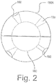
- Figure 2 shows a variant of figure 1 .
- the sensor unit 100 is the same as that of figure 1 .
- the foam ball unit (numbered 150A and shown assembled, is ellipsoidal (shaped like a rugby or North American football ball.)
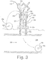
- Figure 3 shows the insertion of a sensor unit 50 (after being fully assembled by joining together pieces 152 and 154) into a pipeline 200 filled with liquid 206 (for example water) flowing in direction 208.
- liquid 206 for example water
- access port 202 also known as an inspection port
- This is normally closed by a valve shown schematically as 204. In the figure the valve is closed
- a sensor unit (shown initially in position 50a) is brought to the site It is then squeezed into the position shown as 50b.
- a cover 230 is then screwed in pressure-tight fashion on the thread 232.
- the cover has a pressure tight gland 235 through which passes a rod 220, terminating in a pusher 221, which is suitably plastic or metal. It also has a small bore 236 to which a suitable value 239 is fastened .
- a line 237 can be connected to the valve.
- the sensor unit is shown in four sequential positions, 50a, 50b and 50c. and 50d.
- position 50a it is resting on the ground surface 210, prior to insertion.
- position 50b the valve 204 has been opened and the foam unit has been compressed to squeeze through the access port 202 above valve 204.
- the cover 230 is put on.
- cover 230 has been secured in pressure tight relation, optionally a vacuum is created in the space between cover 230 and valve 204 by withdrawing air through valve 139 and line 137, to remove air entrained in the foam of ball 50.
- a sterilizant can also be introduced through line 237 and valve 239 if thought desirable.
- Valve 239 is closed and valve 204 is then opened, so that liquid from the pipeline enters the space between valve204 and cover 230.
- rod 220 is pushed manually, to force the sensor unit first into position 50c and then into the pipeline as at 50d, where it recovers its full size.
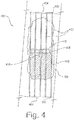
- Figures 4 -6 show a second embodiment of the sensor unit.
- This embodiment is generally numbered 450. It has a cylindrical sensor package 410, and a fabric exterior 420.
- the sensor package contains the same sensors and other components (not shown) as sensor package 100 of Figure 1 .
- Ribs 430 are flexibly attached to one end of sensor package 410 at 432, and terminate at the other end in a flexible connection 436 to a ring 434 which is stretchable.
- Package 410 has a recess 438 into which the ring 434 can lock, as will be shown, and two flat ends 412 and 414. End 412 has a recess 416 into which an insertion tool can fit.
- Ribs 430 support fabric 420, which will form the ball shape.
- the sensor unit 450 is disassembled for insertion into a pipeline.
- the ribs extend upwards beyond the end of the sensor package 410, with the fabric 440 overlaying them.
- the fabric has been cut away to show the ribs.
- the sensor unit is fully assembled. Ring 434 is locked into position in recess 438 and the fabric, pushed by the ribs, has assumed a ball shape with flattened ends 412, 414 at the end of the sensor package 420.
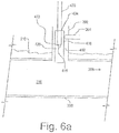
- Figure 6a and 6b show the sequence of insertion of the sensor unit 450 into the pipeline and its final assembly within the pipeline.
- the pipeline is the same as in Figure 3 , and the same numerals will be used to describe it as in Figure 3 .
- the sensor unit 450 is releaseably attached to the end of an insertion device 470, as by a loose compression fit of a rubber bottom end 472 of insertion device 470 in recess 416.
- the insertion device is then lowered through the valve 204 into the pipeline.
- the diameter of cylindrical sensor package 410 is sufficiently small to pass through the access port 202 and past valve 204. In Figure 6a , it is in the process of passing valve 204. In figure 6b it is within the pipeline.
- a sleeve 474 is lowered on insertion device 470 to push ring 434. It pushes until ring 434 snaps into recess-438, at the same time bending the ribs to force the fabric into a ball shape.
- the interior of the ball is filled with the liquid of the pipeline.
- the fabric can be permeable to the liquid, or can be provided with holes (not shown) to permit the liquid to enter.
- the sleeve 474 is then left in position while insertion tool 470 is removed from recess 416. Insertion tool 470 and sleeve 474 are then withdrawn through access port 202 and valve 204 is closed.
- Figure 7 shows a sensor unit 50 moving through the pipeline.
- the sensor unit is more dense than the liquid in the pipeline, so the sensor unit rolls along the bottom of the pipeline. It passes acoustic beacons 701, 702 placed in access ports 202a and 202b respectively. The signals from these beacons are received by the acoustic sensor 118 in sensor unit 50. If it is suspected that a leak is in the area (because for example a previous sensor unit has detected one), a mobile acoustic beacon 715 (shown here positioned on a vehicle 712) can be positioned on the surface near the expected leak. Mobile beacon 715 transmits at very low frequencies (below about 1000Hz) so that its signal will not be attenuated by the earth and the walls of the pipeline.
- Mobile beacon 715 is also provided with a GPS transmitter/receiver 710 so that its position will be known exactly.
- the signals from the beacons are recorded by the acoustic sensor, or they are recorded by recording device 122 to provide a reference to the location of the sensor unit when the recording is made.
- the pipeline is a concrete pipeline wrapped with wire.
- the magnetometer sensors in sensor unit 50 register increased signals when the sensor unit 50 passes a bell and spigot joint between two pipes as at 780, as there are more wires at the joint than in the pipe and because there is a metal insert at that location.
- the magnetometer sensors also note magnetic anomalies if there is corrosion in the wires, and these are recorded on the recording medium or transmitted, or both.
- the location can be determined by elapsed time or by correlation with the acoustic record which is left by the acoustic beacons on the recording medium or which is transmitted.
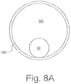
- Figure 8A shows a cross section through pipeline 200, showing how sensor unit 50 rolls along the bottom of the pipeline.
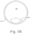
- Figure 8B shows the position that an ellipsoidal sensor takes up, with its larger axis at right angles to the axis of the pipeline.
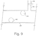
- Figure 9 shows two sensor units of different density, and how they move through the pipeline.
- Sensor unit 50x is of lesser average density than the pipeline, and is used only when the pipeline ifs filled with liquid.
- the pipeline is filled with liquid, so it rolls along the roof of the pipeline. It is larger in diameter than the inspection ports encountered on route, so does not get lodged in such inspection ports.
- Sensor unit 50z is of greater average density than the liquid in the pipeline, so rolls along the bottom.
- the sensor units are shown as being of different diameters, but can be of the same diameter if desired.
- Figure 10 shows one means for removing a sensor from a pipeline, when inspection is finished. This is useful in a pipeline which is at atmospheric pressure.
- a manhole 1000 has been opened by removing manhole cover 1002. and a net 1010 has been positioned to block the pipeline using positioning poles 1012.
- a further portion 1020 of the net, with lifting straps 1022, is positioned on the floor of the pipeline.
- the sensor unit 50 rolls along the floor of the pipeline (the sensor unit in this embodiment being of greater density than the liquid in the pipeline, until it hits net 1010, which prevents it from moving further. It is then on the portion 1020.
- Poles1012 and lifting straps 1022 are operated to pull the sensor unit from the pipeline..
- net portion1020 to engage the sensor unit
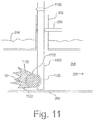
- Figure 1 1 shows a recovery pipe 1100 inserted through an inspection port (also known as an access port) 202, with the valve 204 closed tightly around the pipe.
- Recovery pipe 1100 has its own valve 1102, which is also closed so that pressure does not escape from the pipe.
- Recovery pipe 1100 has attached to it a cone shaped net 1120, which is deployed by resilient ribs 1122, which are compressed during insertion of the recovery pipe into the inspection port, but then expand to deploy the net. The net causes the sensor unit 50 to drift to the apex of the cone.
- a hole 1130 in the inspection pipe is a hole 1130 in the inspection pipe.
- the hole is slightly smaller than the diameter of the ball unit.
- the recovery pipe valve 1102 is opened quickly to atmosphere.
- the sensor unit is slightly compressed and sucked into hole 1130, whereupon it rises and bursts out of the recovery pipe above ground.
- the data recorded from its sensors in its recording unit is analyzed in known fashion. If the data has been transmitted by transmitter 120 before the sensor unit is recovered, the data analysis can begin even before recovery.
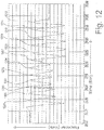
- Figure 12 shows an actual trace made by a singe magnetometer as a spherical sensor unit having a circumference of 2 feet moved along a pipe. A pattern of regular peaks and troughs is seen. The peaks have been numbered 1201-1212 for clarity. Each peak represents the completion of a revolution,. It is therefore easily seen from the graph that the sensor unit travelled 24 feet. The abscissa of the graph is elapsed time in seconds, and the ordinate is the voltage output of the magnetometer.
Claims (10)
- Unité de capteur sans fixation (50) de forme sphérique ou ellipsoïdale pour inspecter une canalisation (200) qui contient un liquide en écoulement (206) de densité moindre que l'unité de capteur (50), dans laquelle(a) l'unité de capteur (50) comprend un boîtier (100) contenant un capteur (112) configuré pour détecter le nombre de révolutions de l'unité de capteur, et des moyens d'enregistrement (120) configurés pour enregistrer le nombre de révolutions détecté par ledit capteur, ledit capteur étant sélectionné parmi (i) au moins un capteur magnétique et (ii) au moins un accéléromètre, et(b) ladite unité de capteur (50) est agencée pour rouler dans la direction du flux du liquide le long du fond de l'intérieur de la canalisation, la force motrice pour son mouvement de roulement étant donnée par le liquide s'écoulant dans la canalisation.
- Unité de capteur (50) selon la revendication 1, dans laquelle l'unité de capteur est sphérique et possède un diamètre de moins d'une moitié et supérieur à un dixième du diamètre de la canalisation à inspecter.
- Unité de capteur (50) selon la revendication 1, dans laquelle l'unité de capteur (50) est ellipsoïdale et la longueur de son grand axe est de moins d'une moitié du diamètre de la canalisation (200) à inspecter.
- Unité de capteur (50) selon l'une quelconque des revendications 1 à 3, comprenant en outre un transmetteur ou transpondeur acoustique qui émet une fréquence supérieure à 20 kilohertz.
- Unité de capteur (50) selon l'une quelconque des revendications 1 à 3, comprenant en outre un transmetteur ou transpondeur acoustique qui transmet une plage de fréquences comprenant une impulsion balayée, dans la plage entre 1 kilohertz et 200 kilohertz.
- Unité de capteur (50) selon l'une quelconque des revendications 1 à 5, dans laquelle ledit capteur comprend trois magnétomètres (112, 114, 116), agencés de manière orthogonale les uns par rapport aux autres.
- Procédé d'inspection d'une canalisation (200) qui contient un liquide s'écoulant (206), comprenant :fournir une unité de capteur (50) qui comprend un boîtier (100) contenant un capteur (112) sélectionné parmi au moins un capteur magnétique et au moins un accéléromètre, et des moyens (120) pour enregistrer des données détectées par ledit capteur, ladite unité de capteur étant de densité supérieure au liquide dans la canalisation à inspecter, etpermettre à l'unité de capteur de rouler le long du fond de l'intérieur de la canalisation, la force motrice pour son mouvement de roulement étant donnée par le liquide s'écoulant dans la canalisation, ladite unité de capteur enregistrant un signal représentatif du nombre de révolutions que la surface de l'unité de capteur a effectué.
- Procédé selon la revendication 7, dans lequel l'unité de capteur (50) comprend un transmetteur ou transpondeur acoustique, et le procédé inclut l'émission de signaux par le transmetteur ou transpondeur et la réception de ces signaux au niveau d'au moins un emplacement le long de la canalisation (200) .
- Procédé selon la revendication 8, dans lequel les signaux sont émis à une fréquence supérieure à 20 kilohertz.
- Procédé selon la revendication 8, dans lequel les signaux sont émis sur une plage de fréquences comprenant une impulsion balayée, dans une plage entre 1 kilohertz et 200 kilohertz.
Applications Claiming Priority (3)
| Application Number | Priority Date | Filing Date | Title |
|---|---|---|---|
| CA2496150 | 2005-02-07 | ||
| EP06705102.9A EP1846689B1 (fr) | 2005-02-07 | 2006-02-07 | Detecteur d'anomalie pour conduites de transport |
| PCT/CA2006/000146 WO2006081671A1 (fr) | 2005-02-07 | 2006-02-07 | Detecteur d'anomalie pour conduites de transport |
Related Parent Applications (2)
| Application Number | Title | Priority Date | Filing Date |
|---|---|---|---|
| EP06705102.9A Division-Into EP1846689B1 (fr) | 2005-02-07 | 2006-02-07 | Detecteur d'anomalie pour conduites de transport |
| EP06705102.9A Division EP1846689B1 (fr) | 2005-02-07 | 2006-02-07 | Detecteur d'anomalie pour conduites de transport |
Publications (2)
| Publication Number | Publication Date |
|---|---|
| EP2902690A1 EP2902690A1 (fr) | 2015-08-05 |
| EP2902690B1 true EP2902690B1 (fr) | 2019-07-31 |
Family
ID=36776907
Family Applications (2)
| Application Number | Title | Priority Date | Filing Date |
|---|---|---|---|
| EP15152055.8A Active EP2902690B1 (fr) | 2005-02-07 | 2006-02-07 | Détecteur d'anomalie pour canalisations |
| EP06705102.9A Active EP1846689B1 (fr) | 2005-02-07 | 2006-02-07 | Detecteur d'anomalie pour conduites de transport |
Family Applications After (1)
| Application Number | Title | Priority Date | Filing Date |
|---|---|---|---|
| EP06705102.9A Active EP1846689B1 (fr) | 2005-02-07 | 2006-02-07 | Detecteur d'anomalie pour conduites de transport |
Country Status (15)
| Country | Link |
|---|---|
| US (1) | US8098063B2 (fr) |
| EP (2) | EP2902690B1 (fr) |
| CN (1) | CN101115950A (fr) |
| AU (1) | AU2006209839B2 (fr) |
| BR (1) | BRPI0608527B1 (fr) |
| CA (1) | CA2596148C (fr) |
| DK (2) | DK2902690T3 (fr) |
| EA (1) | EA011497B1 (fr) |
| ES (2) | ES2748603T3 (fr) |
| HK (1) | HK1213039A1 (fr) |
| IL (1) | IL185057A (fr) |
| MX (1) | MX2007009385A (fr) |
| NZ (1) | NZ560329A (fr) |
| PT (2) | PT1846689E (fr) |
| WO (1) | WO2006081671A1 (fr) |
Cited By (3)
| Publication number | Priority date | Publication date | Assignee | Title |
|---|---|---|---|---|
| DE102020102951A1 (de) | 2020-02-05 | 2021-08-05 | Rosen Swiss Ag | Inspektionsvorrichtung und Inspektionseinheit |
| WO2022157487A1 (fr) * | 2021-01-21 | 2022-07-28 | Cokebusters Limited | Appareil de suivi d'un racleur |
| GB2606568A (en) * | 2021-05-14 | 2022-11-16 | Cokebusters Ltd | Apparatus |
Families Citing this family (90)
| Publication number | Priority date | Publication date | Assignee | Title |
|---|---|---|---|---|
| GB0610362D0 (en) * | 2006-05-13 | 2006-07-05 | Martin Graham | Ferrous mass accumulation debris sensor |
| US9030195B2 (en) | 2006-12-21 | 2015-05-12 | Athena Industrial Technologies, Inc. | Linear structure inspection apparatus and method |
| US20090146835A1 (en) * | 2007-12-05 | 2009-06-11 | Baker Hughes Incorporated | Wireless communication for downhole tools and method |
| FR2930337B1 (fr) * | 2008-04-22 | 2011-03-25 | Freyssinet | Systeme pour obtenir des informations relativement a une canalisation et procede associe |
| WO2009155708A1 (fr) | 2008-06-25 | 2009-12-30 | Pure Technologies Ltd. | Appareil et procédé pour localiser un objet dans un pipeline |
| US7980136B2 (en) * | 2008-09-16 | 2011-07-19 | King Fahd University Of Petroleum And Minerals | Leak and contamination detection micro-submarine |
| DE102009047405A1 (de) * | 2009-12-02 | 2011-06-09 | Endress + Hauser Conducta Gesellschaft für Mess- und Regeltechnik mbH + Co. KG | Vorrichtung zur Bestimmung einer Prozessgröße einer Flüssigkeit in einer Prozessanlage |
| GB2468301B (en) * | 2009-03-03 | 2013-06-12 | Jd7 Ltd | Water mains inspection and servicing |
| US8988969B2 (en) * | 2010-04-23 | 2015-03-24 | Underground Imaging Technologies, Inc. | Detection of cross bores involving buried utilities |
| US20120006562A1 (en) * | 2010-07-12 | 2012-01-12 | Tracy Speer | Method and apparatus for a well employing the use of an activation ball |
| US8584519B2 (en) * | 2010-07-19 | 2013-11-19 | Halliburton Energy Services, Inc. | Communication through an enclosure of a line |
| IT1401474B1 (it) * | 2010-07-20 | 2013-07-26 | Eni Spa | Metodo di monitoraggio e di analisi delle condizioni di una condotta |
| CN103032678B (zh) * | 2011-09-30 | 2015-07-22 | 国际商业机器公司 | 用于监视流体传输管道的状态的方法、装置和系统 |
| RU2482382C1 (ru) * | 2011-11-15 | 2013-05-20 | Сергей Сергеевич Сергеев | Устройство для обнаружения течи в подземной теплотрассе |
| CN102444786B (zh) * | 2011-12-07 | 2013-04-03 | 天津大学 | 检测输油管道泄漏的球形内检测器 |
| CN102927451B (zh) * | 2011-12-07 | 2014-01-01 | 天津大学 | 输油管道微泄漏检测方法 |
| US20140009598A1 (en) * | 2012-03-12 | 2014-01-09 | Siemens Corporation | Pipeline Inspection Piglets |
| FR2989458B1 (fr) * | 2012-04-13 | 2015-07-03 | Commissariat Energie Atomique | Procede et dispsositif de mesures geolocalisees d'une caracteristique d'un fluide en mouvement dans une conduite. |
| CN102644851B (zh) * | 2012-05-08 | 2013-10-09 | 西南石油大学 | 天然气干气管道智能检测球 |
| CN103423600A (zh) * | 2012-05-15 | 2013-12-04 | 中国石油天然气股份有限公司 | 一种液体管道小泄漏检测系统 |
| CN102966850B (zh) * | 2012-11-19 | 2014-01-29 | 天津大学 | 一种管道走向的检测方法 |
| CN102980943A (zh) * | 2012-11-23 | 2013-03-20 | 赣州金信诺电缆技术有限公司 | 电缆金属管内导体接口的检测方法 |
| US20150355045A1 (en) * | 2013-01-28 | 2015-12-10 | Aquarius Spectrum Ltd. | Method and apparatus for detecting leaks in a pipeline network |
| NZ719503A (en) * | 2013-10-30 | 2016-09-30 | Daniel Warren | Method and system for coating a pipe |
| US9571904B2 (en) * | 2013-11-21 | 2017-02-14 | Ge Healthcare Bio-Sciences Ab | Systems and methods for status indication in a single-use biomedical and bioprocess system |
| WO2015128890A2 (fr) * | 2014-02-26 | 2015-09-03 | Eni S.P.A. | Procédé pour empêcher le retrait non autorisé d'un liquide d'au moins un conduit d'évacuation raccordé à un conduit principal pour le transport du liquide précité, en particulier un mélange d'hydrocarbures et d'eau |
| ES2893537T3 (es) | 2014-04-17 | 2022-02-09 | Warren Env & Coating Llc | Método de revestimiento y reparación de una tubería de gran diámetro |
| CN104613320B (zh) * | 2015-01-21 | 2017-05-31 | 西安科技大学 | 管道堵塞点定位装置 |
| WO2016138955A1 (fr) * | 2015-03-04 | 2016-09-09 | Enoware Gmbh | Procédé et dispositif de détection de grandeurs d'état dépendant du lieu dans des conduites |
| CN104764584B (zh) * | 2015-03-20 | 2017-04-05 | 河海大学 | 具有自动计时功能的泥沙颗粒模拟球及模拟计时方法 |
| ES2588214B1 (es) | 2015-04-28 | 2017-09-05 | Aganova S.L. | Dispositivo detector de fugas de agua en tuberías y procedimiento para la detección de fugas |
| CN106287109B (zh) * | 2015-06-09 | 2019-03-12 | 黄建源 | 管路清洗后的检视方法及其检视装置 |
| CN105043312B (zh) * | 2015-08-27 | 2017-11-24 | 浙江省特种设备检验研究院 | 一种压力管道内检测用球形密布式探头超声测厚装置 |
| CN105241612B (zh) * | 2015-10-19 | 2017-08-15 | 西南石油大学 | 一种油管接头螺纹密封性能动态测试装置及方法 |
| CN105333999A (zh) * | 2015-11-28 | 2016-02-17 | 中国人民解放军63680部队 | 基于开源硬件的网络水浸检测和合成语音告警系统 |
| ES2628950B1 (es) | 2016-02-04 | 2018-08-16 | Tubecheck S.L. | Sistema y método para determinar trayectorias en conductos subterráneos |
| CN105805563B (zh) * | 2016-05-10 | 2018-03-27 | 广州丰谱信息技术有限公司 | 基于随路内窥式管道泄漏及堵塞的超声检测装置与方法 |
| US10662759B2 (en) * | 2016-05-13 | 2020-05-26 | Ningbo Wanyou Deepwater Energy Science & Technology Co., Ltd. | Data logger, manufacturing method thereof and pressure sensor thereof |
| US20170328197A1 (en) * | 2016-05-13 | 2017-11-16 | Ningbo Wanyou Deepwater Energy Science & Technolog Co.,Ltd. | Data Logger, Manufacturing Method Thereof and Real-time Measurement System Thereof |
| US20170350241A1 (en) * | 2016-05-13 | 2017-12-07 | Ningbo Wanyou Deepwater Energy Science & Technology Co.,Ltd. | Data Logger and Charger Thereof |
| CN106481987A (zh) * | 2016-09-10 | 2017-03-08 | 浙江大学 | 一种检测管道泄漏的封闭球系统 |
| CN106764247B (zh) * | 2016-11-23 | 2018-10-12 | 中国计量大学 | 压力管道内球形检测器运动控制方法 |
| EP3336505B1 (fr) * | 2016-12-15 | 2020-02-12 | INGU Solutions Inc. | Dispositif de capteur et systèmes permettant de déterminer des paramètres de fluide |
| CN106644302A (zh) * | 2017-02-20 | 2017-05-10 | 广东工业大学 | 一种管道渗漏检测方法、装置及球形系统 |
| WO2018222594A1 (fr) * | 2017-05-29 | 2018-12-06 | Andium Inc. | Journalisation d'événements |
| CN107218514A (zh) * | 2017-06-17 | 2017-09-29 | 浙江大学 | 用于城市供水管网泄漏检测定位球及其应用方法 |
| DE102017114977B4 (de) * | 2017-07-05 | 2022-04-28 | Postberg + Co. GmbH | Wechselarmatur |
| CN107796569B (zh) * | 2017-09-30 | 2020-01-24 | 上海邦芯物联网科技有限公司 | 管道检漏装置、系统和方法 |
| US10769684B1 (en) * | 2017-10-03 | 2020-09-08 | Wells Fargo Bank, N.A. | Property assessment system with buoyancy adjust device |
| CN108036198B (zh) * | 2017-12-05 | 2020-07-03 | 英业达科技有限公司 | 管线漏水智能侦测系统及其方法 |
| WO2019119156A1 (fr) * | 2017-12-22 | 2019-06-27 | Pure Technologies Ltd. | Enveloppe pour équipement d'inspection de pipeline |
| CN108361558A (zh) * | 2018-01-24 | 2018-08-03 | 肖香福 | 一种石油管道安全实时检测装置 |
| CN108286657B (zh) * | 2018-01-25 | 2019-07-16 | 常州新奥燃气工程有限公司 | 听诊球式燃气管道泄漏检测装置及检测方法 |
| GB2571540B (en) | 2018-02-28 | 2020-10-28 | Craley Group Ltd | Improvements in or relating to the monitoring of fluid pipes |
| GB2571798B (en) * | 2018-03-10 | 2022-09-28 | Qinov8 Uk Ltd | System and method for locating leaks in pipelines |
| CN108730676B (zh) * | 2018-03-23 | 2020-08-25 | 昆明理工大学 | 一种用于管道检测的球形机器人 |
| CN108490385B (zh) * | 2018-06-13 | 2023-10-17 | 杭州仁牧科技有限公司 | 多通道海洋水声采集器 |
| IT201800006309A1 (it) * | 2018-06-14 | 2019-12-14 | Dispositivo interattivo a percussione per applicazioni acustiche | |
| WO2020010455A1 (fr) * | 2018-07-10 | 2020-01-16 | Pure Technologies Ltd. | Procédé et appareil de test électromagnétique de tuyaux |
| CN109028992A (zh) * | 2018-08-30 | 2018-12-18 | 中冶赛迪上海工程技术有限公司 | 一种炉窑冷却壁泄漏采集单元及装置、冷却壁检测方法 |
| CN109028994A (zh) * | 2018-08-30 | 2018-12-18 | 中冶赛迪上海工程技术有限公司 | 一种炉窑冷却壁图像信息采集单元及装置、冷却壁检测方法 |
| US11686417B2 (en) * | 2018-09-17 | 2023-06-27 | Timothy Healy | Apparatus for autonomous pipeline assessment |
| RU2697007C1 (ru) * | 2018-09-20 | 2019-08-08 | Публичное акционерное общество "Газпром нефть" | Устройство внутритрубной диагностики технического состояния трубопровода |
| RU2697008C1 (ru) * | 2018-09-20 | 2019-08-08 | Публичное акционерное общество "Газпром нефть" | Способ внутритрубной диагностики технического состояния трубопровода |
| CN109356839B (zh) * | 2018-12-04 | 2023-10-31 | 长虹华意压缩机股份有限公司 | 一种往复式压缩机可靠性实验设备及实验方法 |
| EP3677889B1 (fr) * | 2019-01-02 | 2023-06-28 | INGU Solutions Inc. | Dispositif de capteur pour mesurer des propriétés de fluide et conduit de fluide et procédé d'activation du dispositif de capteur |
| US11293580B2 (en) * | 2019-02-11 | 2022-04-05 | S&B Technical Products, Inc. | Pipeline sphere with tracking device |
| US11629807B1 (en) | 2019-02-12 | 2023-04-18 | Davaus, LLC | Drainage tile inspection system |
| CN109798452A (zh) * | 2019-02-27 | 2019-05-24 | 常州新奥燃气工程有限公司 | 电容式燃气管道泄漏检测装置及检测方法 |
| CN109917835A (zh) * | 2019-03-14 | 2019-06-21 | 福建工程学院 | 一种智能风管功能参数侦测控制系统及方法 |
| CN109899621B (zh) * | 2019-03-26 | 2020-06-30 | 焦作大学 | 一种智能球形管道检测机器人 |
| KR102218957B1 (ko) * | 2019-05-28 | 2021-02-23 | 경일대학교산학협력단 | 구조물의 안전진단을 위해 구조물 내부에 배치된 압력측정장치 |
| CN110470739A (zh) * | 2019-09-03 | 2019-11-19 | 浙江省特种设备科学研究院 | 一种压力管道自漂流式超声内检测智能球 |
| RU2722636C1 (ru) * | 2019-12-11 | 2020-06-02 | Общество с ограниченной ответственностью "Газпромнефть Научно-Технический Центр" (ООО "Газпромнефть НТЦ") | Устройство и способ внутритрубной диагностики технического состояния трубопровода |
| EP3859325A1 (fr) * | 2020-02-03 | 2021-08-04 | INGU Solutions Inc. | Système, procédé et dispositif d'inspection de conduit de fluide |
| CN111396692B (zh) * | 2020-03-30 | 2021-04-13 | 北京交通大学 | 一种重力作用的小口径输油管道球形检测器投放回收装置 |
| US11482092B1 (en) * | 2020-04-30 | 2022-10-25 | United Services Automobile Association (Usaa) | Smart sensors for plumbing systems |
| US11767729B2 (en) | 2020-07-08 | 2023-09-26 | Saudi Arabian Oil Company | Swellable packer for guiding an untethered device in a subterranean well |
| CN112728286B (zh) * | 2020-12-29 | 2024-04-12 | 福州慧源水务科技有限公司 | 一种基于无线声影检测的管道泄漏检测球 |
| CA3142261A1 (fr) | 2021-01-04 | 2022-07-04 | Russell Nde Systems Inc. | Systeme et methode de recuperation de dispositifs de detection de fuites dans une conduite |
| CN112816147B (zh) * | 2021-01-28 | 2022-12-27 | 深圳市水务工程检测有限公司 | 一种基于可变轨道的感应芯片 |
| CN112902030B (zh) * | 2021-01-28 | 2022-12-09 | 深圳市水务工程检测有限公司 | 一种芯片结构 |
| CN113154183A (zh) * | 2021-03-10 | 2021-07-23 | 北京航空工程技术研究中心 | 一种管道内检测系统 |
| CN113865628B (zh) * | 2021-08-25 | 2024-05-07 | 浙江工业大学 | 一种传感器的封装装置及其方法 |
| AU2022202857A1 (en) * | 2021-09-27 | 2023-04-13 | Ingu Solutions Inc. | Systems and methods for determining absolute velocity and position of a sensor device for measuring fluid and fluid conduit properties |
| CN114352845B (zh) * | 2022-01-20 | 2023-11-14 | 西安万飞控制科技有限公司 | 一种用于油气管道内部检测的漂浮球系统及方法 |
| CN114295616B (zh) * | 2022-03-11 | 2022-05-10 | 西南石油大学 | 基于图像识别的套管检测设备 |
| CN114563480B (zh) * | 2022-04-28 | 2022-07-15 | 四川蜀工公路工程试验检测有限公司 | 一种道路混凝土结构强度检测装置 |
| CN114791375B (zh) * | 2022-05-04 | 2022-10-04 | 浙江致远工程管理有限公司 | 用于建材检验的智能设备 |
| CN117366388B (zh) * | 2023-12-08 | 2024-02-27 | 四川德源管道科技股份有限公司 | 一种泡沫球管道内检测器 |
Family Cites Families (12)
| Publication number | Priority date | Publication date | Assignee | Title |
|---|---|---|---|---|
| US5454276A (en) * | 1993-07-30 | 1995-10-03 | Wernicke; Timothy K. | Multi-directional magnetic flux pipe inspection apparatus and method |
| US5672967A (en) * | 1995-09-19 | 1997-09-30 | Southwest Research Institute | Compact tri-axial fluxgate magnetometer and housing with unitary orthogonal sensor substrate |
| US6082193A (en) | 1997-04-11 | 2000-07-04 | Pure Technologies Ltd. | Pipeline monitoring array |
| AR018460A1 (es) * | 1998-06-12 | 2001-11-14 | Shell Int Research | MÉTODO Y DISPOSICIoN PARA MEDIR DATOS DE UN CONDUCTO DE TRANSPORTE DE FLUIDO Y APARATO SENSOR UTILIZADO EN DICHA DISPOSICIoN. |
| GB2352042B (en) * | 1999-07-14 | 2002-04-03 | Schlumberger Ltd | Sensing device |
| GB2379015B (en) | 1999-09-07 | 2003-08-20 | Wrc Plc | A method for detecting and/or locating leaks in a pipe |
| GB0006758D0 (en) * | 2000-03-22 | 2000-05-10 | Copipe Systems Limited | Pipeline pigging device for the non-destructive inspection of the fluid environment in a pipeline |
| CA2329504C (fr) * | 2000-12-22 | 2004-01-20 | Canadian Mining Industry Research Organization/Organisation De Recherche De L'industrie Miniere Canadienne | Dispositif pour la mesure en ligne des proprietes des debits de liquide dans les pipelines |
| CA2361813A1 (fr) | 2001-01-29 | 2002-07-29 | Peter O. Paulson | Analyse electromagnetique a basse frequence de fils de mise en tension du beton precontraint |
| US6958693B2 (en) * | 2002-05-24 | 2005-10-25 | Procter & Gamble Company | Sensor device and methods for using same |
| GB0230207D0 (en) * | 2002-12-27 | 2003-02-05 | Thompson Martin | Leak locator |
| US7526944B2 (en) * | 2004-01-07 | 2009-05-05 | Ashok Sabata | Remote monitoring of pipelines using wireless sensor network |
-
2006
- 2006-02-07 CN CNA2006800042987A patent/CN101115950A/zh active Pending
- 2006-02-07 ES ES15152055T patent/ES2748603T3/es active Active
- 2006-02-07 EA EA200701682A patent/EA011497B1/ru unknown
- 2006-02-07 NZ NZ560329A patent/NZ560329A/en unknown
- 2006-02-07 BR BRPI0608527-0A patent/BRPI0608527B1/pt active IP Right Grant
- 2006-02-07 EP EP15152055.8A patent/EP2902690B1/fr active Active
- 2006-02-07 US US11/814,921 patent/US8098063B2/en active Active
- 2006-02-07 ES ES06705102.9T patent/ES2541103T3/es active Active
- 2006-02-07 AU AU2006209839A patent/AU2006209839B2/en active Active
- 2006-02-07 DK DK15152055.8T patent/DK2902690T3/da active
- 2006-02-07 DK DK06705102.9T patent/DK1846689T3/da active
- 2006-02-07 CA CA2596148A patent/CA2596148C/fr active Active
- 2006-02-07 PT PT67051029T patent/PT1846689E/pt unknown
- 2006-02-07 PT PT151520558T patent/PT2902690T/pt unknown
- 2006-02-07 WO PCT/CA2006/000146 patent/WO2006081671A1/fr active Application Filing
- 2006-02-07 MX MX2007009385A patent/MX2007009385A/es active IP Right Grant
- 2006-02-07 EP EP06705102.9A patent/EP1846689B1/fr active Active
-
2007
- 2007-08-06 IL IL185057A patent/IL185057A/en active IP Right Grant
-
2016
- 2016-01-29 HK HK16101040.0A patent/HK1213039A1/zh unknown
Non-Patent Citations (1)
| Title |
|---|
| None * |
Cited By (5)
| Publication number | Priority date | Publication date | Assignee | Title |
|---|---|---|---|---|
| DE102020102951A1 (de) | 2020-02-05 | 2021-08-05 | Rosen Swiss Ag | Inspektionsvorrichtung und Inspektionseinheit |
| WO2021156433A1 (fr) | 2020-02-05 | 2021-08-12 | Rosen Swiss Ag | Dispositif d'inspection et unité d'inspection |
| WO2022157487A1 (fr) * | 2021-01-21 | 2022-07-28 | Cokebusters Limited | Appareil de suivi d'un racleur |
| GB2606568A (en) * | 2021-05-14 | 2022-11-16 | Cokebusters Ltd | Apparatus |
| EP4092314A1 (fr) * | 2021-05-14 | 2022-11-23 | Cokebusters Limited | Appareil de suivi d'un racleur |
Also Published As
| Publication number | Publication date |
|---|---|
| EP1846689A4 (fr) | 2011-02-16 |
| EP1846689B1 (fr) | 2015-04-08 |
| EP2902690A1 (fr) | 2015-08-05 |
| ES2541103T3 (es) | 2015-07-16 |
| AU2006209839A2 (en) | 2008-12-11 |
| AU2006209839A1 (en) | 2006-08-10 |
| DK2902690T3 (da) | 2019-10-21 |
| IL185057A0 (en) | 2007-12-03 |
| US8098063B2 (en) | 2012-01-17 |
| MX2007009385A (es) | 2008-03-10 |
| BRPI0608527A2 (pt) | 2010-01-12 |
| DK1846689T3 (da) | 2015-06-22 |
| IL185057A (en) | 2012-05-31 |
| US20080204008A1 (en) | 2008-08-28 |
| PT2902690T (pt) | 2019-10-31 |
| HK1213039A1 (zh) | 2016-06-24 |
| EA200701682A1 (ru) | 2008-02-28 |
| NZ560329A (en) | 2009-08-28 |
| ES2748603T3 (es) | 2020-03-17 |
| EP1846689A1 (fr) | 2007-10-24 |
| CA2596148A1 (fr) | 2006-08-10 |
| AU2006209839B2 (en) | 2010-12-02 |
| CN101115950A (zh) | 2008-01-30 |
| BRPI0608527B1 (pt) | 2020-09-24 |
| EA011497B1 (ru) | 2009-04-28 |
| WO2006081671A1 (fr) | 2006-08-10 |
| CA2596148C (fr) | 2014-03-18 |
| PT1846689E (pt) | 2015-08-26 |
Similar Documents
| Publication | Publication Date | Title |
|---|---|---|
| EP2902690B1 (fr) | Détecteur d'anomalie pour canalisations | |
| US11754461B2 (en) | Water leak detector device and leak detection procedure | |
| US7523666B2 (en) | Leak locator | |
| CA2932441C (fr) | Procede et appareil permettant de realiser des inspections en ligne | |
| US9285290B2 (en) | Leak detection apparatus | |
| BRPI0917504B1 (pt) | Dispositivo e método para avaliar problemas de resistência de parede de tubulação | |
| JP6068184B2 (ja) | 管路漏水調査方法及び管路漏水調査システム | |
| JP2015145804A (ja) | 地下通水管の漏水検出方法 | |
| Kurtz | Developments in a free-swimming acoustic leak detection system for water transmission pipelines | |
| van Pol et al. | The Future of In-Line Inspection: Free-Floating Smart Sensors | |
| EA042587B1 (ru) | Прибор для обнаружения утечек воды в трубопроводах и способ обнаружения утечек |
Legal Events
| Date | Code | Title | Description |
|---|---|---|---|
| PUAI | Public reference made under article 153(3) epc to a published international application that has entered the european phase |
Free format text: ORIGINAL CODE: 0009012 |
|
| 17P | Request for examination filed |
Effective date: 20150122 |
|
| AC | Divisional application: reference to earlier application |
Ref document number: 1846689 Country of ref document: EP Kind code of ref document: P |
|
| AK | Designated contracting states |
Kind code of ref document: A1 Designated state(s): AT BE BG CH CY CZ DE DK EE ES FI FR GB GR HU IE IS IT LI LT LU LV MC NL PL PT RO SE SI SK TR |
|
| AX | Request for extension of the european patent |
Extension state: AL BA HR MK YU |
|
| REG | Reference to a national code |
Ref country code: HK Ref legal event code: DE Ref document number: 1213039 Country of ref document: HK |
|
| STAA | Information on the status of an ep patent application or granted ep patent |
Free format text: STATUS: EXAMINATION IS IN PROGRESS |
|
| 17Q | First examination report despatched |
Effective date: 20161130 |
|
| GRAP | Despatch of communication of intention to grant a patent |
Free format text: ORIGINAL CODE: EPIDOSNIGR1 |
|
| STAA | Information on the status of an ep patent application or granted ep patent |
Free format text: STATUS: GRANT OF PATENT IS INTENDED |
|
| INTG | Intention to grant announced |
Effective date: 20190228 |
|
| GRAS | Grant fee paid |
Free format text: ORIGINAL CODE: EPIDOSNIGR3 |
|
| GRAA | (expected) grant |
Free format text: ORIGINAL CODE: 0009210 |
|
| STAA | Information on the status of an ep patent application or granted ep patent |
Free format text: STATUS: THE PATENT HAS BEEN GRANTED |
|
| AC | Divisional application: reference to earlier application |
Ref document number: 1846689 Country of ref document: EP Kind code of ref document: P |
|
| AK | Designated contracting states |
Kind code of ref document: B1 Designated state(s): AT BE BG CH CY CZ DE DK EE ES FI FR GB GR HU IE IS IT LI LT LU LV MC NL PL PT RO SE SI SK TR |
|
| AX | Request for extension of the european patent |
Extension state: AL BA HR MK YU |
|
| REG | Reference to a national code |
Ref country code: CH Ref legal event code: EP Ref country code: GB Ref legal event code: FG4D |
|
| REG | Reference to a national code |
Ref country code: AT Ref legal event code: REF Ref document number: 1161267 Country of ref document: AT Kind code of ref document: T Effective date: 20190815 |
|
| REG | Reference to a national code |
Ref country code: IE Ref legal event code: FG4D |
|
| REG | Reference to a national code |
Ref country code: DE Ref legal event code: R096 Ref document number: 602006058410 Country of ref document: DE |
|
| REG | Reference to a national code |
Ref country code: DK Ref legal event code: T3 Effective date: 20191015 |
|
| REG | Reference to a national code |
Ref country code: PT Ref legal event code: SC4A Ref document number: 2902690 Country of ref document: PT Date of ref document: 20191031 Kind code of ref document: T Free format text: AVAILABILITY OF NATIONAL TRANSLATION Effective date: 20191023 |
|
| REG | Reference to a national code |
Ref country code: SE Ref legal event code: TRGR |
|
| REG | Reference to a national code |
Ref country code: NL Ref legal event code: FP |
|
| REG | Reference to a national code |
Ref country code: LT Ref legal event code: MG4D |
|
| REG | Reference to a national code |
Ref country code: AT Ref legal event code: MK05 Ref document number: 1161267 Country of ref document: AT Kind code of ref document: T Effective date: 20190731 |
|
| PG25 | Lapsed in a contracting state [announced via postgrant information from national office to epo] |
Ref country code: LT Free format text: LAPSE BECAUSE OF FAILURE TO SUBMIT A TRANSLATION OF THE DESCRIPTION OR TO PAY THE FEE WITHIN THE PRESCRIBED TIME-LIMIT Effective date: 20190731 Ref country code: AT Free format text: LAPSE BECAUSE OF FAILURE TO SUBMIT A TRANSLATION OF THE DESCRIPTION OR TO PAY THE FEE WITHIN THE PRESCRIBED TIME-LIMIT Effective date: 20190731 Ref country code: BG Free format text: LAPSE BECAUSE OF FAILURE TO SUBMIT A TRANSLATION OF THE DESCRIPTION OR TO PAY THE FEE WITHIN THE PRESCRIBED TIME-LIMIT Effective date: 20191031 |
|
| PG25 | Lapsed in a contracting state [announced via postgrant information from national office to epo] |
Ref country code: LV Free format text: LAPSE BECAUSE OF FAILURE TO SUBMIT A TRANSLATION OF THE DESCRIPTION OR TO PAY THE FEE WITHIN THE PRESCRIBED TIME-LIMIT Effective date: 20190731 Ref country code: IS Free format text: LAPSE BECAUSE OF FAILURE TO SUBMIT A TRANSLATION OF THE DESCRIPTION OR TO PAY THE FEE WITHIN THE PRESCRIBED TIME-LIMIT Effective date: 20191130 |
|
| REG | Reference to a national code |
Ref country code: GR Ref legal event code: EP Ref document number: 20190403316 Country of ref document: GR Effective date: 20200213 |
|
| REG | Reference to a national code |
Ref country code: ES Ref legal event code: FG2A Ref document number: 2748603 Country of ref document: ES Kind code of ref document: T3 Effective date: 20200317 |
|
| PG25 | Lapsed in a contracting state [announced via postgrant information from national office to epo] |
Ref country code: TR Free format text: LAPSE BECAUSE OF FAILURE TO SUBMIT A TRANSLATION OF THE DESCRIPTION OR TO PAY THE FEE WITHIN THE PRESCRIBED TIME-LIMIT Effective date: 20190731 |
|
| PG25 | Lapsed in a contracting state [announced via postgrant information from national office to epo] |
Ref country code: PL Free format text: LAPSE BECAUSE OF FAILURE TO SUBMIT A TRANSLATION OF THE DESCRIPTION OR TO PAY THE FEE WITHIN THE PRESCRIBED TIME-LIMIT Effective date: 20190731 Ref country code: RO Free format text: LAPSE BECAUSE OF FAILURE TO SUBMIT A TRANSLATION OF THE DESCRIPTION OR TO PAY THE FEE WITHIN THE PRESCRIBED TIME-LIMIT Effective date: 20190731 Ref country code: EE Free format text: LAPSE BECAUSE OF FAILURE TO SUBMIT A TRANSLATION OF THE DESCRIPTION OR TO PAY THE FEE WITHIN THE PRESCRIBED TIME-LIMIT Effective date: 20190731 |
|
| PG25 | Lapsed in a contracting state [announced via postgrant information from national office to epo] |
Ref country code: CZ Free format text: LAPSE BECAUSE OF FAILURE TO SUBMIT A TRANSLATION OF THE DESCRIPTION OR TO PAY THE FEE WITHIN THE PRESCRIBED TIME-LIMIT Effective date: 20190731 Ref country code: IS Free format text: LAPSE BECAUSE OF FAILURE TO SUBMIT A TRANSLATION OF THE DESCRIPTION OR TO PAY THE FEE WITHIN THE PRESCRIBED TIME-LIMIT Effective date: 20200224 Ref country code: SK Free format text: LAPSE BECAUSE OF FAILURE TO SUBMIT A TRANSLATION OF THE DESCRIPTION OR TO PAY THE FEE WITHIN THE PRESCRIBED TIME-LIMIT Effective date: 20190731 |
|
| REG | Reference to a national code |
Ref country code: DE Ref legal event code: R097 Ref document number: 602006058410 Country of ref document: DE |
|
| PLBE | No opposition filed within time limit |
Free format text: ORIGINAL CODE: 0009261 |
|
| STAA | Information on the status of an ep patent application or granted ep patent |
Free format text: STATUS: NO OPPOSITION FILED WITHIN TIME LIMIT |
|
| PG2D | Information on lapse in contracting state deleted |
Ref country code: IS |
|
| PG25 | Lapsed in a contracting state [announced via postgrant information from national office to epo] |
Ref country code: IS Free format text: LAPSE BECAUSE OF FAILURE TO SUBMIT A TRANSLATION OF THE DESCRIPTION OR TO PAY THE FEE WITHIN THE PRESCRIBED TIME-LIMIT Effective date: 20191030 |
|
| 26N | No opposition filed |
Effective date: 20200603 |
|
| PG25 | Lapsed in a contracting state [announced via postgrant information from national office to epo] |
Ref country code: SI Free format text: LAPSE BECAUSE OF FAILURE TO SUBMIT A TRANSLATION OF THE DESCRIPTION OR TO PAY THE FEE WITHIN THE PRESCRIBED TIME-LIMIT Effective date: 20190731 |
|
| REG | Reference to a national code |
Ref country code: CH Ref legal event code: PL |
|
| PG25 | Lapsed in a contracting state [announced via postgrant information from national office to epo] |
Ref country code: MC Free format text: LAPSE BECAUSE OF FAILURE TO SUBMIT A TRANSLATION OF THE DESCRIPTION OR TO PAY THE FEE WITHIN THE PRESCRIBED TIME-LIMIT Effective date: 20190731 Ref country code: LU Free format text: LAPSE BECAUSE OF NON-PAYMENT OF DUE FEES Effective date: 20200207 |
|
| PG25 | Lapsed in a contracting state [announced via postgrant information from national office to epo] |
Ref country code: CH Free format text: LAPSE BECAUSE OF NON-PAYMENT OF DUE FEES Effective date: 20200229 Ref country code: LI Free format text: LAPSE BECAUSE OF NON-PAYMENT OF DUE FEES Effective date: 20200229 |
|
| PG25 | Lapsed in a contracting state [announced via postgrant information from national office to epo] |
Ref country code: CY Free format text: LAPSE BECAUSE OF FAILURE TO SUBMIT A TRANSLATION OF THE DESCRIPTION OR TO PAY THE FEE WITHIN THE PRESCRIBED TIME-LIMIT Effective date: 20190731 |
|
| PGFP | Annual fee paid to national office [announced via postgrant information from national office to epo] |
Ref country code: IE Payment date: 20230227 Year of fee payment: 18 Ref country code: FR Payment date: 20230223 Year of fee payment: 18 Ref country code: FI Payment date: 20230223 Year of fee payment: 18 Ref country code: ES Payment date: 20230301 Year of fee payment: 18 Ref country code: DK Payment date: 20230227 Year of fee payment: 18 |
|
| PGFP | Annual fee paid to national office [announced via postgrant information from national office to epo] |
Ref country code: SE Payment date: 20230227 Year of fee payment: 18 Ref country code: PT Payment date: 20230119 Year of fee payment: 18 Ref country code: IT Payment date: 20230221 Year of fee payment: 18 Ref country code: GR Payment date: 20230228 Year of fee payment: 18 Ref country code: GB Payment date: 20230227 Year of fee payment: 18 Ref country code: BE Payment date: 20230227 Year of fee payment: 18 |
|
| PGFP | Annual fee paid to national office [announced via postgrant information from national office to epo] |
Ref country code: ES Payment date: 20240301 Year of fee payment: 19 Ref country code: NL Payment date: 20240226 Year of fee payment: 19 |
|
| PGFP | Annual fee paid to national office [announced via postgrant information from national office to epo] |
Ref country code: DE Payment date: 20240228 Year of fee payment: 19 |