EP2899468A1 - Gargerät mit einem Luftschacht und einem Zuleitkanal - Google Patents
Gargerät mit einem Luftschacht und einem Zuleitkanal Download PDFInfo
- Publication number
- EP2899468A1 EP2899468A1 EP15151316.5A EP15151316A EP2899468A1 EP 2899468 A1 EP2899468 A1 EP 2899468A1 EP 15151316 A EP15151316 A EP 15151316A EP 2899468 A1 EP2899468 A1 EP 2899468A1
- Authority
- EP
- European Patent Office
- Prior art keywords
- door
- air
- opening
- duct
- cooking appliance
- Prior art date
- Legal status (The legal status is an assumption and is not a legal conclusion. Google has not performed a legal analysis and makes no representation as to the accuracy of the status listed.)
- Granted
Links
- 238000010411 cooking Methods 0.000 title claims abstract description 44
- 238000001816 cooling Methods 0.000 claims abstract description 29
- 238000009423 ventilation Methods 0.000 claims abstract description 6
- 238000011144 upstream manufacturing Methods 0.000 claims description 8
- 230000000694 effects Effects 0.000 description 2
- 238000005192 partition Methods 0.000 description 2
- 230000003716 rejuvenation Effects 0.000 description 2
- 230000008878 coupling Effects 0.000 description 1
- 238000010168 coupling process Methods 0.000 description 1
- 238000005859 coupling reaction Methods 0.000 description 1
- 238000007599 discharging Methods 0.000 description 1
- 238000005516 engineering process Methods 0.000 description 1
- 238000009434 installation Methods 0.000 description 1
- 238000002955 isolation Methods 0.000 description 1
- 238000004519 manufacturing process Methods 0.000 description 1
- 239000011435 rock Substances 0.000 description 1
Images


Classifications
-
- F—MECHANICAL ENGINEERING; LIGHTING; HEATING; WEAPONS; BLASTING
- F24—HEATING; RANGES; VENTILATING
- F24C—DOMESTIC STOVES OR RANGES ; DETAILS OF DOMESTIC STOVES OR RANGES, OF GENERAL APPLICATION
- F24C15/00—Details
- F24C15/006—Arrangements for circulation of cooling air
-
- F—MECHANICAL ENGINEERING; LIGHTING; HEATING; WEAPONS; BLASTING
- F24—HEATING; RANGES; VENTILATING
- F24C—DOMESTIC STOVES OR RANGES ; DETAILS OF DOMESTIC STOVES OR RANGES, OF GENERAL APPLICATION
- F24C15/00—Details
- F24C15/02—Doors specially adapted for stoves or ranges
- F24C15/04—Doors specially adapted for stoves or ranges with transparent panels
Definitions
- the invention relates to a cooking appliance with a cooking chamber which is bounded by walls of a muffle.
- the cooking compartment can be closed by a door at the front.
- the door has a ventilation duct through which cooling air can be conducted and can be diverted from a cover opening in an upper door cover.
- the muffle has a muffle cover over which an air shaft is formed. In this air duct, the cooling air discharged from the door cover can be introduced via an inlet opening formed in an air shaft bottom and then diverted from a housing of the household appliance.
- Such a cooking appliance is known from the prior art. So this is for example in the EP 2 278 227 A1 shown. In addition, also from the corresponding EP 2 444 737 A1 disclosed.
- a cooking device as it is in Fig. 1 shown is known.
- a door 2 In the schematic sectional view shown there in an upper region of the cooking appliance 1, a door 2 is shown.
- the door 2 comprises an outer door panel 3 and at least one inner door panel 4, which faces a cooking chamber 5 in the closed state of the door 2.
- a handle 6 is arranged on an outer side of the door outer pane 3.
- a ventilation channel 7 is formed between the at least two discs 3 and 4, a ventilation channel 7 is formed. Through this, a cooling air 8 is passed from bottom to top. This occurs in the upper region of the door 2 from an upper door cover 9, which is also commonly referred to as a top panel, from.
- the cooking chamber 5 is limited by a muffle 10.
- the muffle 10 comprises a muffle cover 11 and facing the front of the door 2 and a Muffelflansch 12.
- the Muffelflansch 12 is in particular completely circumferential and thus formed like a frame.
- a fan 14 is disposed at a rear end of the air duct 13. By means of the fan 14, air 15 is sucked in and blown to a front outlet opening 16 of the air duct 13.
- the air shaft 13 is arranged so that this outlet opening 16 is arranged between an upper edge of the door 2 and a lower edge of a control panel 17.
- This duct 13 has an air shaft bottom 18.
- this air shaft bottom 18 is adjacent to a front end 18 a, which ends in the region of the muffle flange 12, adjacent to a Heilschachtverjüngungselement 19 is formed. Due to the shape of this Gutschachtverjüngungselements 19, which is formed like a ramp or like a rock, a Venturi principle is achieved. As a result, downstream of this air duct tapering element 19, the cooling air 8 which emerges between the door cover 9 and the muffle flange 12 and exits the door 2 is automatically sucked or sucked in and out of the opening 16 with the air flow 20 generated by the blower 14 blown out.
- Such a design of an air duct 13 is also referred to as a single air shaft.
- the functionally the air from the door 2 and thus the cooling air 8 is not sucked in the duct 13 to the fan 14, but blown away directly from the fan 14 with the entry into the duct 13, without flowing substantially in the direction of the blower 14 to be able to.
- the blower 14 is operated in this single-duct principle as a pressurized blower.
- a further known embodiment of a cooking device 1 is shown. Again, an upper portion of the cooking device 1 is shown in a schematic sectional view.
- no duct 13 is shown, which is designed as a single air duct, but an air duct 13 is shown, which is designed as a so-called double air duct.
- the cooling air 8 which flows out of the door 2 is introduced into a first air duct section 13a and sucked by the arrangement and operation of the blower 14 in the direction of the blower 14.
- the air passage portion 13a is separated from a second air passage portion 13c by a partition wall 13b.
- the air flow sucked in from outside or externally by the blower 14 is conducted to the opening 16 via this second air duct section 13c. Due to the arrangement of the air duct sections 13a and 13c and the fan 14 and in particular also its oppressive operating mode, the cooling air 8 is sucked from the first air duct section 13a to the blower 14 and then automatically picked up by the air flow 20 and forwarded to the opening 16.
- An inventive cooking appliance comprises a cooking chamber which is bounded by walls of a muffle.
- the muffle has on the front side a charging opening, which can be closed by a door.
- the door has a ventilation duct through which cooling air can be conducted and can be diverted from a cover opening in an upper door cover.
- an air duct is formed, in which the discharged from the door cover cooling air via an inlet opening formed in an air shaft bottom can be introduced and is ausleitbar from a housing of the household appliance.
- the Zuleitkanal extends starting from the inlet opening obliquely downwards and directed towards the door front.
- the air outlet is favored again, since the Zuleitkanal is designed in a straight line and thus no circumferential deflections of the air and thus turbulence are formed. Furthermore, this makes it possible to realize a very space-saving and also manufacturing technology preferred embodiment.
- the Zuleitkanal can not be rectilinear sine, for example, be angled, so that, for example, a first portion is perpendicular from the inlet opening down to which then branches off a horizontal portion in the direction of the cover opening.
- the Zuleitkanal is then in particular L-shaped.
- the inlet opening with respect to a door facing the front end of the air shaft floor upstream of the air duct formed flowing back air By such a configuration and thus also achieved orientation of Zuleitkanals the coupling of this specific duct to a muffle flange of the muffle and / or a door cover is improved.
- a conventional configuration of the door cover and / or the muffle flange does not have to be changed.
- the placement of the cooking appliance with specific air ducts can be improved and thus in particular made more variable and flexible.
- the redesign of other components of the cooking appliance, in particular the Muffelflansches and / or the door cover, are therefore no longer necessary.
- the Zuleitkanal opens with an upper opening viewed in the flow direction of the air gaplessly into the inlet opening. Unwanted flow leaks and consequent disadvantages of the operating principle for discharging the cooling air from the door via the air duct and from this out of the housing can be avoided.
- the Zuleitkanal is integrally formed on the air shaft bottom.
- the supply channel opens with a lower opening facing away from the inlet opening to a flange opening formed in a muffle flange.
- the flange opening is in the closed state of the door of the cover opening aligned.
- an air duct tapering element is formed in the flow direction of the cooling air in the air duct upstream of the inlet opening.
- this is advantageous in that a Venturi principle can then be generated, through which a vacuum zone results downstream of this air duct taper element automatically results in a suction of the cooling air from the door into the Zuleitkanal and from this into the duct.
- the air shaft is designed as a single air shaft and upstream of the Lucasschachtverjüngungsungselement a fan is arranged. Due to the air flow generated by the blower in the direction of the air duct tapering element into the air duct and the air duct tapering element, a negative pressure zone is created in the region of the inlet opening, through which the cooling air is sucked out of the door and out of the air shaft in the air shaft on an end of the air shaft facing away from the fan duct Housing is divertable.
- This single duct is thus characterized to the effect that the coming of the door cooling air flow is not sucked in the duct itself in the direction of the blower, but only passes into the negative pressure zone behind the Heilschachtverjüngungselement and then directed away in a direction of the fan immediately to the opening of the duct and there is discharged from the fan.
- the air duct with the Zuleitkanal so in particular a single air shaft can be provided, which can be used easily and compatible in a cooking appliance whose Muffelflansch and / or door cover and thus the door itself are designed and designed so that they are fundamental to Installation of a double duct are designed. It can then be used in the components door and muffle respectively one equal component, which can be equipped tode Kunststoffaus terminate both a single air duct and a double air duct compatible.
- a flange opening is formed, which is opposite to the cover opening in the closed state in the closed state.
- the muffle flange with its flange opening and the door cover are formed with its cover opening so that instead of a Single duct formed air duct compatible a designed as a double duct shaft duct can be installed.
- the double air duct is designed as at least upstream of the inlet opening air duct rejuvenating element-free air shaft.
- a cooking appliance 1 with a housing 1a is shown in a front view, which has a cooking chamber 5 which is bounded by walls of a muffle 10.
- the muffle 10 can be closed in its feed opening by a door 2.
- a duct 13 is formed above a muffle ceiling 11.
- This front has an opening 16 which is disposed between a TÜberberkante and a lower edge of a control panel 17 and opens accordingly.
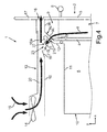
- Fig. 4 is the cooking appliance 1 according to Fig. 3 along the section line IV-IV, but shown only in the upper area.
- the door cover 9 comprises a front wall 3 facing away from the inclined wall 9a, which merges into a substantially horizontal top wall 9b.
- the inclined wall 9a comprises a cover opening 9c, from which the cooling air flow 8 exits the door 2. He then passes through an aligned with this cover opening 9c flange opening 12b in a Zuleitkanal 21 having an upper opening 21a and a lower opening 21 b.
- the air shaft bottom 18 includes downstream of the air duct tapering element 19 an inlet opening 22 into which the supply channel 21 opens.
- the supply passage 21 is formed integrally with the air shaft bottom 18, so that the openings 21a and 22 are the same.
- the Zuleitkanal 21 thus preferably opens completely into the air shaft bottom 18th
- the supply channel 21 opens completely into the muffle flange 12.
- This gaplessness is considered in particular in the direction of the flow of the cooling air flow or the cooling air 8.
- the Zuleitkanal 21 is oriented starting from the inlet opening 22 obliquely downwards and towards the door 2 directed towards. This means that viewed in the direction of the cooling air flow of this Zuleitkanal 21 is oriented obliquely upwards and in the depth direction of the cooking appliance 1 and thus in the negative x-direction to the rear. Thus, viewed in the x direction, the lower opening 21 b is positioned further forward than the upper opening 21 a. In addition, it can be seen that the upper opening 21 a is formed immediately adjacent, but downstream of the air flow 20 in the duct 13 to the air duct tapering element 19.
- this specific duct 13 which represents a single duct
- the design of the door 2 with, in particular, the door cover 9 and the muffle flange 12 is thus designed so that both the single air shaft according to the explanation in Fig. 4 as well as the double air shaft according to the explanation in Fig. 2 can be installed in the cooking appliance 1. For this purpose, it is then no longer necessary to change this door cover 9 and the muffle flange 12.
- this is designed as a double air duct duct 13 is formed without such a duct chamfer 19. This is because in the double air duct principle no vacuum zone is provided for the realization of a venturi principle.
Landscapes
- Engineering & Computer Science (AREA)
- Chemical & Material Sciences (AREA)
- Combustion & Propulsion (AREA)
- Mechanical Engineering (AREA)
- General Engineering & Computer Science (AREA)
- Baking, Grill, Roasting (AREA)
Abstract
Description
- Die Erfindung betrifft ein Gargerät mit einem Garraum, der durch Wände einer Muffel begrenzt ist. Der Garraum ist frontseitig durch eine Tür verschließbar. Die Tür weist einen Lüftungskanal auf, durch welchen Kühlluft leitbar und aus einer Abdeckungsöffnung in einer oberen Türabdeckung ausleitbar ist. Die Muffel weist eine Muffeldecke auf, über welcher ein Luftschacht ausgebildet ist. In diesem Luftschacht ist die aus der Türabdeckung ausgeleitete Kühlluft über eine in einem Luftschachtboden ausgebildete Einleitöffnung einleitbar und dann aus einem Gehäuse des Haushaltsgeräts ausleitbar.
- Ein derartiges Gargerät ist aus dem Stand der Technik bekannt. So ist dies beispielsweise in der
EP 2 278 227 A1 gezeigt. Darüber hinaus ist auch Entsprechendes aus derEP 2 444 737 A1 offenbart. - Darüber hinaus ist auch ein Gargerät, wie es in
Fig. 1 gezeigt ist, bekannt. Bei der dort gezeigten schematischen Schnittdarstellung in einem oberen Bereich des Gargeräts 1 ist eine Tür 2 gezeigt. Die Tür 2 umfasst eine Türaußenscheibe 3 und zumindest eine Türinnenscheibe 4, die einem Garraum 5 im geschlossenen Zustand der Tür 2 zugewandt ist. Ein Griff 6 ist an einer Außenseite der Türaußenscheibe 3 angeordnet. Zwischen den zumindest zwei Scheiben 3 und 4 ist ein Lüftungskanal 7 ausgebildet. Durch diesen wird von unten nach oben eine Kühlluft 8 geleitet. Diese tritt im oberen Bereich der Tür 2 aus einer oberen Türabdeckung 9, die üblicherweise auch als Topblende bezeichnet wird, aus. - Wie in
Fig. 1 zu erkennen ist, ist der Garraum 5 durch eine Muffel 10 begrenzt. Die Muffel 10 umfasst eine Muffeldecke 11 und frontseitig und somit der Tür 2 zugewandt einen Muffelflansch 12. Der Muffelflansch 12 ist insbesondere vollständig umlaufend und somit rahmenartig ausgebildet. In vertikaler Richtung und somit in y-Richtung über der Muffel 10 und somit auch der Muffeldecke 11 ist ein Luftschacht 13 ausgebildet. Ein Gebläse 14 ist an einem hinteren Ende des Luftschachts 13 angeordnet. Mittels des Gebläses 14 wird Luft 15 angesaugt und zu einer vorderen Austrittsöffnung 16 des Luftschachts 13 geblasen. Der Luftschacht 13 ist so angeordnet, dass diese Austrittsöffnung 16 zwischen einer Oberkante der Tür 2 und einer Unterkante einer Bedienblende 17 angeordnet ist. - Dieser Luftschacht 13 weist einen Luftschachtboden 18 auf. In diesem Luftschachtboden 18 ist benachbart zu einem frontseitigen Ende 18a, welches im Bereich des Muffelflansches 12 endet, benachbart dazu ein Luftschachtverjüngungselement 19 ausgebildet. Durch die Gestalt dieses Luftschachtverjüngungselements 19, das rampenartig beziehungsweise schanzenartig ausgebildet ist, wird ein Venturi-Prinzip erreicht. Dadurch wird stromabwärts dieses Luftschachtverjüngungselements 19 die zwischen der Türabdeckung 9 und dem Muffelflansch 12 eingeleitete Kühlluft 8, die aus der Tür 2 austritt, automatisch eingesaugt beziehungsweise angesaugt und mit dem Luftstrom 20, wie er durch das Gebläse 14 erzeugt wird, dann aus der Öffnung 16 ausgeblasen. Eine derartige Ausgestaltung eines Luftkanals 13 wird auch als Einfachluftschacht bezeichnet. Bei dieser Ausgestaltung wird somit funktionell die Luft aus der Tür 2 und somit die Kühlluft 8 nicht im Luftschacht 13 zum Gebläse 14 hin gesaugt, sondern unmittelbar mit dem Eintritt in den Luftschacht 13 dem Gebläse 14 abgewandt ausgeblasen, ohne wesentlich in Richtung des Gebläses 14 strömen zu können. Das Gebläse 14 wird bei diesem Einfachluftschachtprinzip als drückendes Gebläse betrieben.
- In
Fig. 2 ist eine weitere bekannte Ausführung eines Gargeräts 1 gezeigt. Auch hier ist in einer schematischen Schnittdarstellung ein oberer Bereich des Gargeräts 1 gezeigt. Im Unterschied zur Ausgestaltung gemäßFig. 1 ist hier kein Luftschacht 13 gezeigt, der als Einfachluftschacht ausgebildet ist, sondern ein Luftschacht 13 gezeigt, der als sogenannter Doppelluftschacht ausgebildet ist. Bei dieser Ausführung wird durch eine Öffnung 12a in dem Muffelflansch 12 die Kühlluft 8, die aus der Tür 2 ausströmt, in einen ersten Luftkanalabschnitt 13a eingeleitet und durch die Anordnung und den Betrieb des Gebläses 14 in Richtung des Gebläses 14 angesaugt. Der Luftkanalabschnitt 13a ist durch eine Trennwand 13b von einem zweiten Luftkanalabschnitt 13c separiert. Der von dem Gebläse 14 von außen beziehungsweise extern angesaugte Luftstrom wird über diesen zweiten Luftkanalabschnitt 13c zur Öffnung 16 geleitet. Durch die Anordnung der Luftkanalabschnitte 13a und 13c sowie dem Gebläse 14 und insbesondere auch dessen drückende Betriebsart wird die Kühlluft 8 von den ersten Luftkanalabschnitt 13a zum Gebläse 14 gesaugt und dort dann automatisch durch den Luftstrom 20 aufgenommen und weitergeleitet zur Öffnung 16. - Es ist Aufgabe der vorliegenden Erfindung, ein Gargerät zu schaffen, bei welchem eine flexiblere und variablere Ausführung der aus der Tür abgeleiteten Luft erreicht ist.
- Diese Aufgabe wird durch ein Gargerät, das die Merkmale nach Anspruch 1 aufweist, gelöst.
- Ein erfindungsgemäßes Gargerät umfasst einen Garraum, der durch Wände einer Muffel begrenzt ist. Die Muffel weist frontseitig eine Beschickungsöffnung auf, welche durch eine Tür verschließbar ist. Die Tür weist einen Lüftungskanal auf, durch welche Kühlluft leitbar und aus einer Abdeckungsöffnung in einer oberen Türabdeckung ausleitbar ist. Über einer Muffeldecke ist ein Luftschacht ausgebildet, in welchen die aus der Türabdeckung ausgeleitete Kühlluft über eine in einem Luftschachtboden ausgebildete Einleitöffnung einleitbar ist und aus einem Gehäuse des Haushaltsgeräts ausleitbar ist. Ein wesentlicher Gedanke der Erfindung ist darin zu sehen, dass zwischen der Einleitöffnung und der Abdecköffnung ein Zuleitkanal zum Zuleiten der Kühlluft aus der Tür in den Luftschacht ausgebildet ist. Eine derartige Ausgestaltung des Luftschachts ermöglicht eine Verbesserung der Luftabführung einer in der Tür geleiteten Kühlluft aus dem Gargerät heraus.
- Insbesondere erstreckt sich der Zuleitkanal ausgehend von der Einleitöffnung schräg nach unten und vorne zur Tür hin gerichtet. Dadurch wird die Luftabführung nochmals begünstigt, da der Zuleitkanal geradlinig gestaltet ist und somit keine umfänglichen Umlenkungen der Luft und somit Verwirbelungen gebildet werden. Des Weiteren lässt sich dadurch eine sehr platzsparende und auch fertigungstechnisch bevorzugte Ausführung realisieren.
- Der Zuleitkanal kann jedoch auch nicht geradlinig ausgebildet sine, beispielsweise gewinkelt sein, so dass beispielsweise ein erstes Teilstück senkrecht von der Einleitöffnung nach unten steht, an welches dann ein horizontales Teilstück in Richtung der Abdecköffnung abzweigt. Bei dieser Ausführung ist der Zuleitkanal dann insbesondere L-förmig.
- Insbesondere ist vorgesehen, dass die Einleitöffnung gegenüber einem der Tür zugewandten vorderen Ende des Luftschachtbodens stromaufwärts der im Luftschacht strömenden Luft zurückversetzt ausgebildet ist. Durch eine derartige Ausgestaltung und damit auch erreichte Orientierung des Zuleitkanals wird die Ankopplung dieses spezifischen Luftschachts an einen Muffelflansch der Muffel und/oder einer Türabdeckung verbessert. Dies insbesondere dahingehend, dass auch bei diesem spezifischen Luftschachttyp und dessen spezifizierte Ausgestaltung eine herkömmliche Ausgestaltung der Türabdeckung und/oder des Muffelflansches nicht verändert werden muss. Dadurch kann die Bestückbarkeit des Gargeräts mit spezifischen Luftschächten verbessert und somit insbesondere variabler und flexibler erfolgen. Die Umkonstruktion von weiteren Komponenten des Gargeräts, insbesondere des Muffelflansches und/oder der Türabdeckung, sind daher nicht mehr erforderlich.
- Vorzugsweise ist vorgesehen, dass der Zuleitkanal mit einer oberen Öffnung in Strömungsrichtung der Luft betrachtet lückenlos in die Einleitöffnung mündet. Unerwünschte Strömungslecks und daraus sich ergebende Nachteile am Wirkprinzip zum Ausleiten der Kühlluft aus der Tür über den Luftschacht und von diesem aus dem Gehäuse heraus können dadurch vermieden werden.
- Vorzugsweise ist vorgesehen, dass der Zuleitkanal einstückig an dem Luftschachtboden ausgebildet ist. Die oben genannten Vorteile werden dadurch nochmals bekräftigt und darüber hinaus eine mechanisch stabile Ausgestaltung des Luftschachts mit dem Zuleitkanal erreicht.
- Vorzugsweise ist vorgesehen, dass der Zuleitkanal mit einer der Einleitöffnung abgewandten unteren Öffnung an eine in einem Muffelflansch ausgebildete Flanschöffnung mündet. Die Flanschöffnung liegt im geschlossenen Zustand der Tür der Abdecköffnung fluchtend gegenüber. Durch diese Ausgestaltung wird ein sehr geradliniger Weg von der Tür zum Luftschacht erreicht, so dass auch hier die zugrunde gelegten Strömungsprinzipien bestmöglich zum Tragen kommen.
- Vorzugsweise ist vorgesehen, dass in Strömungsrichtung der Kühlluft in dem Luftschacht stromaufwärts der Einleitöffnung ein Luftschachtverjüngungselement ausgebildet ist. Dies ist bei diesem spezifischen Luftschacht dahingehend vorteilhaft, dass dann ein Venturi-Prinzip erzeugt werden kann, durch welches sich aufgrund einer Unterdruckzone stromabwärts dieses Luftschachtverjüngungselements automatisch ein Ansaugen der Kühlluft aus der Tür in den Zuleitkanal und von diesem in den Luftschacht ergibt.
- Vorzugsweise ist vorgesehen, dass der Luftschacht als Einfachluftschacht ausgebildet ist und stromaufwärts des Luftschachtverjüngungselements ein Gebläse angeordnet ist. Durch den durch das Gebläse in Richtung des Luftschachtverjüngungselements erzeugten Luftstrom in den Luftschacht und das Luftschachtverjüngungselement ist im Bereich der Einleitöffnung eine Unterdruckzone erzeugt, durch welche die Kühlluft aus der Tür angesaugt und mit dem Luftstrom im Luftschacht auf einem dem Gebläse abgewandten Ende des Luftschachts aus dem Gehäuse ausleitbar ist. Dieser Einfachluftschacht zeichnet sich also dahingehend aus, dass der von der Tür kommende Kühlluftstrom in dem Luftschacht selbst nicht in Richtung des Gebläses gesaugt wird, sondern nur in die Unterdruckzone hinter dem Luftschachtverjüngungselement gelangt und dann in eine Richtung abgewandt des Gebläses unverzüglich zur Öffnung des Luftschachts geleitet und dort aus dem Gebläse ausgeleitet wird.
- Durch die Spezifikation des Luftschachts mit dem Zuleitkanal kann also insbesondere auch ein Einfachluftschacht bereitgestellt werden, der problemlos und kompatibel in ein Gargerät eingesetzt werden kann, dessen Muffelflansch und/oder Türabdeckung und somit auch die Tür selbst so konzipiert und ausgelegt sind, dass sie grundlegend zum Einbau eines Doppelluftschachts ausgelegt sind. Es kann also dann bei den Komponenten Tür und Muffelflansch jeweils ein Gleichbauteil verwendet werden, welches zur Kühlluftausförderung sowohl mit einem Einfachluftschacht als auch mit einem Doppelluftschacht kompatibel bestückt werden kann.
- Insbesondere ist vorgesehen, dass in einem Muffelflansch eine Flanschöffnung ausgebildet ist, die im geschlossenen Zustand der Tür der Abdecköffnung fluchtend gegenüberliegt. Auch dies ist eine bevorzugte Ausführung, da somit die Unterdruckzone im Gerät selbst ausgebildet ist. Strömungstechnische Nachteile, wie sie bei Ausgestaltungen im druckschriftlichen oben eingangs genannten Stand der Technik auftreten, sind dadurch verhindert.
- Insbesondere ist vorgesehen, dass der Muffelflansch mit seiner Flanschöffnung und die Türabdeckung mit ihrer Abdecköffnung so ausgebildet sind, dass anstelle eines als Einfachluftschacht ausgebildeten Luftschachts kompatibel ein als Doppelluftschacht ausgebildeter Luftschacht einbaubar ist.
- Insbesondere ist vorgesehen, dass der Doppelluftschacht als zumindest stromaufwärts der Einleitöffnung luftschachtverjüngungselementloser Luftschacht ausgebildet ist.
- Weitere Merkmale der Erfindung ergeben sich aus den Ansprüchen, den Figuren und der Figurenbeschreibung. Die vorstehend in der Beschreibung genannten Merkmale und Merkmalskombinationen, sowie die nachfolgend in der Figurenbeschreibung genannten und/oder in den Figuren alleine gezeigten Merkmale und Merkmalskombinationen sind nicht nur in der jeweils angegebenen Kombination, sondern auch in anderen Kombinationen oder in Alleinstellung verwendbar, ohne den Rahmen der Erfindung zu verlassen. Es sind somit auch Ausführungen von der Erfindung als umfasst und offenbart anzusehen, die in den Figuren nicht explizit gezeigt und erläutert sind, jedoch durch separierte Merkmalskombinationen aus den erläuterten Ausführungen hervorgehen und erzeugbar sind.
- Ausführungsbeispiele der Erfindung werden nachfolgend anhand schematischer Zeichnungen näher erläutert. Es zeigen:
- Fig. 1
- eine aus dem Stand der Technik bekannte Ausführung eines Gargeräts mit einem Einfachluftschacht;
- Fig. 2
- eine aus dem Stand der Technik bekannte Ausführung eines Gargeräts mit einem Doppelluftschacht;
- Fig. 3
- eine schematische Frontansicht auf ein Ausführungsbeispiel eines erfindungsgemäßen Gargeräts; und
- Fig. 4
- eine schematische Schnittdarstellung eines oberen Bereichs des Gargeräts gemäß
Fig. 3 . - In den Figuren werden gleiche oder funktionsgleiche Elemente mit den gleichen Bezugszeichen versehen.
- In
Fig. 3 ist in einer Frontansicht ein Gargerät 1 mit einem Gehäuse 1a gezeigt, welches einen Garraum 5, der durch Wände einer Muffel 10 begrenzt ist, aufweist. Frontseitig ist die Muffel 10 in ihrer Beschickungsöffnung durch eine Tür 2 verschließbar. In vertikaler Richtung ist oberhalb einer Muffeldecke 11 ein Luftschacht 13 ausgebildet. Dieser weist frontseitig eine Öffnung 16 auf, die zwischen einer Türoberkante und einer Unterkante einer Bedienblende 17 angeordnet ist und entsprechend mündet. - In
Fig. 4 ist das Gargerät 1 gemäßFig. 3 entlang der Schnittlinie IV-IV, jedoch nur im oberen Bereich dargestellt. - Bezüglich der in
Fig. 4 verwendeten Bezugszeichen wird auf die Erläuterungen zuFig. 1 hingewiesen. - Darüber hinaus umfasst die Türabdeckung 9 eine der Frontscheibe 3 abgewandte Schrägwand 9a, die in eine im Wesentlichen horizontale Oberwand 9b übergeht. Die Schrägwand 9a umfasst eine Abdecköffnung 9c, aus der der Kühlluftstrom 8 aus der Tür 2 austritt. Er gelangt dann durch eine mit dieser Abdecköffnung 9c fluchtend ausgebildete Flanschöffnung 12b in einen Zuleitkanal 21, der eine obere Öffnung 21a und eine untere Öffnung 21 b aufweist.
- Der Luftschachtboden 18 umfasst stromabwärts des Luftschachtverjüngungselements 19 eine Einleitöffnung 22, in die der Zuleitkanal 21 mündet. Insbesondere ist der Zuleitkanal 21 einstückig mit dem Luftschachtboden 18 ausgebildet, so dass die Öffnungen 21a und 22 die gleichen sind. Der Zuleitkanal 21 mündet somit vorzugsweise lückenlos in den Luftschachtboden 18.
- Insbesondere ist auch vorgesehen, dass der Zuleitkanal 21 lückenlos in den Muffelflansch 12 mündet.
- Diese Lückenlosigkeit bezieht sich insbesondere in Richtung der Strömung des Kühlluftstroms bzw. der Kühlluft 8 betrachtet.
- Wie aus der Darstellung in
Fig. 4 zu erkennen ist, ist der Zuleitkanal 21 ausgehend von der Einleitöffnung 22 schräg nach unten und vorne zur Tür 2 hin gerichtet orientiert. Dies bedeutet, dass in Richtung des Kühlluftstroms betrachtet dieser Zuleitkanal 21 schräg nach oben und in Tiefenrichtung des Gargeräts 1 und somit in negativer x-Richtung betrachtet nach hinten orientiert ist. In x-Richtung betrachtet ist somit die untere Öffnung 21 b weiter vorne positioniert als die obere Öffnung 21 a. Darüber hinaus ist zu erkennen, dass die obere Öffnung 21 a unmittelbar benachbart, aber stromabwärts des Luftstroms 20 im Luftschacht 13 zum Luftschachtverjüngungselement 19 ausgebildet ist. Es bildet sich stromab dieses Luftschachtverjüngungselements 19 und insbesondere im Bereich der Eintrittsöffnung beziehungsweise Einleitöffnung 22 eine Unterdruckzone 23, durch welche ein automatisches Ansaugen des Kühlluftstroms 8 aus der Tür 2 in den Luftschacht 13 erreicht wird. - Insbesondere ist auch vorgesehen, dass anstelle dieses spezifischen Luftschachts 13, der einen Einfachluftschacht darstellt, das ansonsten gleiche Gargerät 1 kompatibel beispielsweise auch mit dem Doppelluftschacht, wie er in
Fig. 2 erläutert wurde, bestückt werden kann. Insbesondere ist somit die Ausgestaltung der Tür 2 mit insbesondere der Türabdeckung 9 und dem Muffelflansch 12 so gestaltet, dass sowohl der Einfachluftschacht gemäß der Erläuterung inFig. 4 als auch der Doppelluftschacht gemäß der Erläuterung inFig. 2 in das Gargerät 1 eingebaut werden können. Dazu ist dann nicht mehr erforderlich, diese Türabdeckung 9 und den Muffelflansch 12 zu verändern. - Wie dazu auch aus der Darstellung in
Fig. 2 zu erkennen ist, ist dieser als Doppelluftschacht ausgebildete Luftschacht 13 ohne ein derartiges Luftschachtverjüngungselement 19 ausgebildet. Dies, da bei dem Doppelluftschachtprinzip keine Unterdruckzone zur Realisierung eines Venturi-Prinzips vorgesehen ist. -
- 1
- Gargerät
- 2
- Tür
- 3
- Türaußenscheibe
- 4
- Türinnenscheibe
- 5
- Garraum
- 6
- Griff
- 7
- Lüftungskanal
- 8
- Kühlluft
- 9
- Türabdeckung
- 9a
- Schrägwand
- 9b
- Oberwand
- 9c
- Abdecköffnung
- 10
- Muffel
- 11
- Muffeldecke
- 12
- Muffelflansch
- 12a
- Öffnung
- 12b
- Flanschöffnung
- 13
- Luftschacht
- 13a
- Erster Luftkanalabschnitt
- 13b
- Trennwand
- 13c
- Zweiter Luftkanalabschnitt
- 14
- Gebläse
- 15
- Luft
- 16
- Austrittsöffnung
- 17
- Bedienblende
- 18
- Luftschachtboden
- 18a
- Frontseitiges Ende
- 19
- Luftschachtverjüngungselement
- 20
- Luftstrom
- 21
- Zuleitkanal
- 21a
- Obere Öffnung
- 21b
- Untere Öffnung
- 22
- Einleitöffnung
- 23
- Unterdruckzone
Claims (11)
- Gargerät (1) mit einem Garraum (5), der durch Wände einer Muffel (10) begrenzt ist, und frontseitig durch eine Tür (2) verschließbar ist, und die Tür (2) einen Lüftungskanal (7) aufweist, durch welchen Kühlluft (8) leitbar und aus einer Abdeckungsöffnung in einer oberen Türabdeckung (9) ausleitbar ist, wobei über einer Muffeldecke (11) ein Luftschacht (13) ausgebildet ist, in welchen die aus der Türabdeckung (9) ausgeleitete Kühlluft (8) über eine Einleitöffnung einleitbar ist und aus einem Gehäuse (1a) des Haushaltsgeräts (1) ausleitbar ist, dadurch gekennzeichnet, dass zwischen einer in einem Luftschachtboden (18) ausgebildeten Einleitöffnung (22) und der Abdecköffnung (9c) ein Zuleitkanal (21) zum Zuleiten der Kühlluft (8) aus der Tür (2) in den Luftschacht (13) ausgebildet ist.
- Gargerät (1) nach Anspruch 1, dadurch gekennzeichnet, dass sich der Zuleitkanal (21) ausgehend von der Einleitöffnung (22) schräg nach unten und vorne zur Tür (2) hin gerichtet erstreckt.
- Gargerät (1) nach Anspruch 1 oder 2, dadurch gekennzeichnet, dass die Einleitöffnung (22) gegenüber einem der Tür (2) zugewandten vorderen Ende (18a) des Luftschachtbodens (18) stromaufwärts zurück versetzt ausgebildet ist.
- Gargerät (1) nach einem der vorhergehenden Ansprüche, dadurch gekennzeichnet, dass der Zuleitkanal (21) mit einer oberen Öffnung (21 a) lückenlos in die Einleitöffnung (22) mündet.
- Gargerät (1) nach einem der vorhergehenden Ansprüche, dadurch gekennzeichnet, dass der Zuleitkanal (21) einstückig an dem Luftschachtboden (18) ausgebildet ist.
- Gargerät (1) nach einem der vorhergehenden Ansprüche, dadurch gekennzeichnet, dass der Zuleitkanal (21) mit einer der Einleitöffnung (22) abgewandten unteren Öffnung (21 b) an eine in einem Muffelflansch (12) ausgebildete Flanschöffnung (12b) mündet, wobei die Flanschöffnung (12b) im geschlossenen Zustand der Tür (2) der Abdecköffnung (9c) fluchtend gegenüber liegt.
- Gargerät (1) nach einem der vorhergehenden Ansprüche, dadurch gekennzeichnet, dass in Strömungsrichtung des Luftstroms (20) in dem Luftschacht (13) stromaufwärts der Einleitöffnung (22) ein Luftschachtverjüngungselement (19) ausgebildet ist.
- Gargerät (1) nach Anspruch 7, dadurch gekennzeichnet, dass der Luftschacht (13) als Einfachluftschacht ausgebildet ist und stromaufwärts des Luftschachtverjüngungselements (19) ein Gebläse (14) angeordnet ist, wobei durch den durch das Gebläse (14) in Richtung des Luftschachtverjüngungselements (19) erzeugten Luftstrom (20) und das Luftschachtverjüngungselement (19) im Bereich der Einleitöffnung (22) eine Unterdruckzone (23) erzeugt ist, durch welche die Kühlluft (8) aus der Tür (2) angesaugt und mit dem Luftstrom (20) im Luftschacht (13) auf einem dem Gebläse (14) abgewandten Ende des Luftschachts (13) aus dem Gehäuse (1a) ausleitbar ist.
- Gargerät (1) nach einem der vorhergehenden Ansprüche, dadurch gekennzeichnet, dass in einem Muffelflansch (12) eine Flanschöffnung (12b) ausgebildet ist, die im geschlossenen Zustand der Tür (2) der Abdecköffnung (9c) fluchtend gegenüber liegt.
- Gargerät (1) nach Anspruch 9, dadurch gekennzeichnet, dass der Muffelflansch (12) mit seiner Flanschöffnung (12b) und die Türabdeckung (9) mit ihrer Abdecköffnung (9c) so ausgebildet sind, dass anstelle eines als Einfachluftschachts ausgebildeten Luftschachts (13) kompatibel ein als Doppelluftschacht ausgebildeter Luftschacht (13) einbaubar ist.
- Gargerät (1) nach Anspruch 10, dadurch gekennzeichnet, dass der Doppelluftschacht als zumindest stromaufwärts der Einleitöffnung (22) luftschachtverjüngungselementloser Luftschacht (13) ausgebildet ist.
Priority Applications (1)
| Application Number | Priority Date | Filing Date | Title |
|---|---|---|---|
| PL15151316T PL2899468T3 (pl) | 2014-01-27 | 2015-01-15 | Urządzenie do gotowania z szybem powietrznym i z kanałem zasilającym |
Applications Claiming Priority (1)
| Application Number | Priority Date | Filing Date | Title |
|---|---|---|---|
| DE102014201424.7A DE102014201424A1 (de) | 2014-01-27 | 2014-01-27 | Gargerät mit einem Luftschacht und einem Zuleitkanal |
Publications (2)
| Publication Number | Publication Date |
|---|---|
| EP2899468A1 true EP2899468A1 (de) | 2015-07-29 |
| EP2899468B1 EP2899468B1 (de) | 2017-11-01 |
Family
ID=52339078
Family Applications (1)
| Application Number | Title | Priority Date | Filing Date |
|---|---|---|---|
| EP15151316.5A Active EP2899468B1 (de) | 2014-01-27 | 2015-01-15 | Gargerät mit einem Luftschacht und einem Zuleitkanal |
Country Status (4)
| Country | Link |
|---|---|
| EP (1) | EP2899468B1 (de) |
| DE (1) | DE102014201424A1 (de) |
| ES (1) | ES2655256T3 (de) |
| PL (1) | PL2899468T3 (de) |
Families Citing this family (1)
| Publication number | Priority date | Publication date | Assignee | Title |
|---|---|---|---|---|
| CN112438615B (zh) * | 2019-08-31 | 2022-02-18 | 宁波方太厨具有限公司 | 一种门体及具有该门体的烹饪装置 |
Citations (8)
| Publication number | Priority date | Publication date | Assignee | Title |
|---|---|---|---|---|
| EP1022517A1 (de) * | 1999-01-25 | 2000-07-26 | CANDY S.p.A. | Tür für pyrolytischen Ofen |
| WO2003093731A1 (de) * | 2002-05-06 | 2003-11-13 | BSH Bosch und Siemens Hausgeräte GmbH | Energiesparende gargerätetür mit niedriger fronttemperatur |
| FR2876781A1 (fr) * | 2004-10-18 | 2006-04-21 | Brandt Ind Sas | Four de cuisson comportant un dispositif de ventilation des organes de commande |
| US20070267402A1 (en) * | 2006-05-17 | 2007-11-22 | Harned Gary V | Oven With An Articulating And Retractable Door |
| EP2278227A2 (de) | 2009-07-15 | 2011-01-26 | Miele & Cie. KG | Haushaltgerät |
| EP2333424A1 (de) * | 2009-12-10 | 2011-06-15 | Electrolux Home Products Corporation N.V. | Herdtür mit Belüftung für einen Haushaltsherd |
| DE102010038806A1 (de) * | 2010-08-03 | 2012-02-09 | BSH Bosch und Siemens Hausgeräte GmbH | Backofen |
| EP2444737A1 (de) | 2010-10-25 | 2012-04-25 | BSH Bosch und Siemens Hausgeräte GmbH | Vorrichtung zur Ausblasung von Wrasen aus einem Gargerät sowie Gargerät mit einer derartigen Vorrichtung |
Family Cites Families (1)
| Publication number | Priority date | Publication date | Assignee | Title |
|---|---|---|---|---|
| DE102007005718A1 (de) * | 2007-02-05 | 2008-08-07 | BSH Bosch und Siemens Hausgeräte GmbH | Lüftungsblende und Ofen |
-
2014
- 2014-01-27 DE DE102014201424.7A patent/DE102014201424A1/de not_active Withdrawn
-
2015
- 2015-01-15 PL PL15151316T patent/PL2899468T3/pl unknown
- 2015-01-15 ES ES15151316.5T patent/ES2655256T3/es active Active
- 2015-01-15 EP EP15151316.5A patent/EP2899468B1/de active Active
Patent Citations (8)
| Publication number | Priority date | Publication date | Assignee | Title |
|---|---|---|---|---|
| EP1022517A1 (de) * | 1999-01-25 | 2000-07-26 | CANDY S.p.A. | Tür für pyrolytischen Ofen |
| WO2003093731A1 (de) * | 2002-05-06 | 2003-11-13 | BSH Bosch und Siemens Hausgeräte GmbH | Energiesparende gargerätetür mit niedriger fronttemperatur |
| FR2876781A1 (fr) * | 2004-10-18 | 2006-04-21 | Brandt Ind Sas | Four de cuisson comportant un dispositif de ventilation des organes de commande |
| US20070267402A1 (en) * | 2006-05-17 | 2007-11-22 | Harned Gary V | Oven With An Articulating And Retractable Door |
| EP2278227A2 (de) | 2009-07-15 | 2011-01-26 | Miele & Cie. KG | Haushaltgerät |
| EP2333424A1 (de) * | 2009-12-10 | 2011-06-15 | Electrolux Home Products Corporation N.V. | Herdtür mit Belüftung für einen Haushaltsherd |
| DE102010038806A1 (de) * | 2010-08-03 | 2012-02-09 | BSH Bosch und Siemens Hausgeräte GmbH | Backofen |
| EP2444737A1 (de) | 2010-10-25 | 2012-04-25 | BSH Bosch und Siemens Hausgeräte GmbH | Vorrichtung zur Ausblasung von Wrasen aus einem Gargerät sowie Gargerät mit einer derartigen Vorrichtung |
Also Published As
| Publication number | Publication date |
|---|---|
| PL2899468T3 (pl) | 2018-03-30 |
| DE102014201424A1 (de) | 2015-07-30 |
| ES2655256T3 (es) | 2018-02-19 |
| EP2899468B1 (de) | 2017-11-01 |
Similar Documents
| Publication | Publication Date | Title |
|---|---|---|
| DE102013210053B3 (de) | Luftausströmer | |
| DE202007012095U1 (de) | Gleichluftsystem für eine Abzugshaube, insbesondere zur Anwendung an einem Kochfeld | |
| EP3096674A1 (de) | Fluidblock für ein endoskopbedienteil und endoskop | |
| EP3071004A1 (de) | Schaltschrankanordnung | |
| EP3141410B1 (de) | Luftführungsgehäuse und eine belüftungs-, heizungs- oder klimaanlage mit einem solchen luftführungsgehäuse | |
| EP2610557A1 (de) | Backofen mit Unterhitze und Heißluft | |
| EP2251105B1 (de) | Abzug mit vorgelagerter Fensterführung | |
| DE102017215457B4 (de) | Klimaanlage eines Fahrzeugs | |
| DE10351476A1 (de) | Verfahren und Gargerät zur verbesserten Frischluftzufuhr | |
| DE102007039635A1 (de) | Dunstabzugshaube | |
| DE102013202959B4 (de) | Handtrockner | |
| EP2899468B1 (de) | Gargerät mit einem Luftschacht und einem Zuleitkanal | |
| EP1839766B1 (de) | Abzug mit vorderer Abluftöffnung | |
| WO2021073693A1 (de) | Vorrichtung zur be- und/oder entlüftung von räumen | |
| EP3807576B1 (de) | Gargerät | |
| DE102010062147A1 (de) | Hausgerät mit einem Außengehäuse, welches eine Seitenwand aufweist und einen Luftführungskanal umfasst | |
| DE102018113818B9 (de) | Dunstabzugssystem | |
| EP4083517A1 (de) | Kombinationsgerät mit kochfeld und dunstabzugsvorrichtung | |
| DE102006014683A1 (de) | Luftausströmer | |
| DE102019109401B4 (de) | Lüftereinrichtung zum Ansaugen und Ableiten von Wrasen nach unterhalb eines Kochfeldes und Kochfeld | |
| EP4056759A1 (de) | Strassenfertiger mit absaugeinrichtung | |
| DE102010042891A1 (de) | Vorrichtung zur Ausblasung von Wrasen aus einem Gargerät sowie Gargerät mit einer derartigen Vorrichtung | |
| EP0043504B1 (de) | Aussenwandkasten für die Verbrennungsluft- und Abgaskanäle eines mit einem Brennersystem arbeitenden Gerätes | |
| DE102013014766A1 (de) | Luftführungseinrichtung für einen Kraftwagen sowie Baukastensystem | |
| DE102017118484A1 (de) | Luftführung für ein Gargerät mit einem Garraum und Gargerät mit einem Garraum und einer Luftführung |
Legal Events
| Date | Code | Title | Description |
|---|---|---|---|
| PUAI | Public reference made under article 153(3) epc to a published international application that has entered the european phase |
Free format text: ORIGINAL CODE: 0009012 |
|
| 17P | Request for examination filed |
Effective date: 20150115 |
|
| AK | Designated contracting states |
Kind code of ref document: A1 Designated state(s): AL AT BE BG CH CY CZ DE DK EE ES FI FR GB GR HR HU IE IS IT LI LT LU LV MC MK MT NL NO PL PT RO RS SE SI SK SM TR |
|
| AX | Request for extension of the european patent |
Extension state: BA ME |
|
| 17P | Request for examination filed |
Effective date: 20160129 |
|
| RBV | Designated contracting states (corrected) |
Designated state(s): AL AT BE BG CH CY CZ DE DK EE ES FI FR GB GR HR HU IE IS IT LI LT LU LV MC MK MT NL NO PL PT RO RS SE SI SK SM TR |
|
| 17Q | First examination report despatched |
Effective date: 20161027 |
|
| GRAP | Despatch of communication of intention to grant a patent |
Free format text: ORIGINAL CODE: EPIDOSNIGR1 |
|
| INTG | Intention to grant announced |
Effective date: 20170531 |
|
| GRAS | Grant fee paid |
Free format text: ORIGINAL CODE: EPIDOSNIGR3 |
|
| GRAA | (expected) grant |
Free format text: ORIGINAL CODE: 0009210 |
|
| AK | Designated contracting states |
Kind code of ref document: B1 Designated state(s): AL AT BE BG CH CY CZ DE DK EE ES FI FR GB GR HR HU IE IS IT LI LT LU LV MC MK MT NL NO PL PT RO RS SE SI SK SM TR |
|
| REG | Reference to a national code |
Ref country code: GB Ref legal event code: FG4D Free format text: NOT ENGLISH |
|
| REG | Reference to a national code |
Ref country code: CH Ref legal event code: EP Ref country code: AT Ref legal event code: REF Ref document number: 942421 Country of ref document: AT Kind code of ref document: T Effective date: 20171115 |
|
| REG | Reference to a national code |
Ref country code: IE Ref legal event code: FG4D Free format text: LANGUAGE OF EP DOCUMENT: GERMAN |
|
| REG | Reference to a national code |
Ref country code: DE Ref legal event code: R096 Ref document number: 502015002212 Country of ref document: DE |
|
| REG | Reference to a national code |
Ref country code: FR Ref legal event code: PLFP Year of fee payment: 4 |
|
| REG | Reference to a national code |
Ref country code: ES Ref legal event code: FG2A Ref document number: 2655256 Country of ref document: ES Kind code of ref document: T3 Effective date: 20180219 |
|
| REG | Reference to a national code |
Ref country code: NL Ref legal event code: MP Effective date: 20171101 |
|
| REG | Reference to a national code |
Ref country code: LT Ref legal event code: MG4D |
|
| PG25 | Lapsed in a contracting state [announced via postgrant information from national office to epo] |
Ref country code: LT Free format text: LAPSE BECAUSE OF FAILURE TO SUBMIT A TRANSLATION OF THE DESCRIPTION OR TO PAY THE FEE WITHIN THE PRESCRIBED TIME-LIMIT Effective date: 20171101 Ref country code: FI Free format text: LAPSE BECAUSE OF FAILURE TO SUBMIT A TRANSLATION OF THE DESCRIPTION OR TO PAY THE FEE WITHIN THE PRESCRIBED TIME-LIMIT Effective date: 20171101 Ref country code: NL Free format text: LAPSE BECAUSE OF FAILURE TO SUBMIT A TRANSLATION OF THE DESCRIPTION OR TO PAY THE FEE WITHIN THE PRESCRIBED TIME-LIMIT Effective date: 20171101 Ref country code: NO Free format text: LAPSE BECAUSE OF FAILURE TO SUBMIT A TRANSLATION OF THE DESCRIPTION OR TO PAY THE FEE WITHIN THE PRESCRIBED TIME-LIMIT Effective date: 20180201 Ref country code: SE Free format text: LAPSE BECAUSE OF FAILURE TO SUBMIT A TRANSLATION OF THE DESCRIPTION OR TO PAY THE FEE WITHIN THE PRESCRIBED TIME-LIMIT Effective date: 20171101 |
|
| PG25 | Lapsed in a contracting state [announced via postgrant information from national office to epo] |
Ref country code: BG Free format text: LAPSE BECAUSE OF FAILURE TO SUBMIT A TRANSLATION OF THE DESCRIPTION OR TO PAY THE FEE WITHIN THE PRESCRIBED TIME-LIMIT Effective date: 20180201 Ref country code: GR Free format text: LAPSE BECAUSE OF FAILURE TO SUBMIT A TRANSLATION OF THE DESCRIPTION OR TO PAY THE FEE WITHIN THE PRESCRIBED TIME-LIMIT Effective date: 20180202 Ref country code: LV Free format text: LAPSE BECAUSE OF FAILURE TO SUBMIT A TRANSLATION OF THE DESCRIPTION OR TO PAY THE FEE WITHIN THE PRESCRIBED TIME-LIMIT Effective date: 20171101 Ref country code: HR Free format text: LAPSE BECAUSE OF FAILURE TO SUBMIT A TRANSLATION OF THE DESCRIPTION OR TO PAY THE FEE WITHIN THE PRESCRIBED TIME-LIMIT Effective date: 20171101 Ref country code: IS Free format text: LAPSE BECAUSE OF FAILURE TO SUBMIT A TRANSLATION OF THE DESCRIPTION OR TO PAY THE FEE WITHIN THE PRESCRIBED TIME-LIMIT Effective date: 20180301 Ref country code: RS Free format text: LAPSE BECAUSE OF FAILURE TO SUBMIT A TRANSLATION OF THE DESCRIPTION OR TO PAY THE FEE WITHIN THE PRESCRIBED TIME-LIMIT Effective date: 20171101 |
|
| PG25 | Lapsed in a contracting state [announced via postgrant information from national office to epo] |
Ref country code: DK Free format text: LAPSE BECAUSE OF FAILURE TO SUBMIT A TRANSLATION OF THE DESCRIPTION OR TO PAY THE FEE WITHIN THE PRESCRIBED TIME-LIMIT Effective date: 20171101 Ref country code: CY Free format text: LAPSE BECAUSE OF FAILURE TO SUBMIT A TRANSLATION OF THE DESCRIPTION OR TO PAY THE FEE WITHIN THE PRESCRIBED TIME-LIMIT Effective date: 20171101 Ref country code: EE Free format text: LAPSE BECAUSE OF FAILURE TO SUBMIT A TRANSLATION OF THE DESCRIPTION OR TO PAY THE FEE WITHIN THE PRESCRIBED TIME-LIMIT Effective date: 20171101 Ref country code: SK Free format text: LAPSE BECAUSE OF FAILURE TO SUBMIT A TRANSLATION OF THE DESCRIPTION OR TO PAY THE FEE WITHIN THE PRESCRIBED TIME-LIMIT Effective date: 20171101 Ref country code: CZ Free format text: LAPSE BECAUSE OF FAILURE TO SUBMIT A TRANSLATION OF THE DESCRIPTION OR TO PAY THE FEE WITHIN THE PRESCRIBED TIME-LIMIT Effective date: 20171101 |
|
| REG | Reference to a national code |
Ref country code: DE Ref legal event code: R097 Ref document number: 502015002212 Country of ref document: DE |
|
| PG25 | Lapsed in a contracting state [announced via postgrant information from national office to epo] |
Ref country code: SM Free format text: LAPSE BECAUSE OF FAILURE TO SUBMIT A TRANSLATION OF THE DESCRIPTION OR TO PAY THE FEE WITHIN THE PRESCRIBED TIME-LIMIT Effective date: 20171101 Ref country code: RO Free format text: LAPSE BECAUSE OF FAILURE TO SUBMIT A TRANSLATION OF THE DESCRIPTION OR TO PAY THE FEE WITHIN THE PRESCRIBED TIME-LIMIT Effective date: 20171101 |
|
| REG | Reference to a national code |
Ref country code: CH Ref legal event code: PL |
|
| PLBE | No opposition filed within time limit |
Free format text: ORIGINAL CODE: 0009261 |
|
| STAA | Information on the status of an ep patent application or granted ep patent |
Free format text: STATUS: NO OPPOSITION FILED WITHIN TIME LIMIT |
|
| PG25 | Lapsed in a contracting state [announced via postgrant information from national office to epo] |
Ref country code: MT Free format text: LAPSE BECAUSE OF FAILURE TO SUBMIT A TRANSLATION OF THE DESCRIPTION OR TO PAY THE FEE WITHIN THE PRESCRIBED TIME-LIMIT Effective date: 20171101 |
|
| 26N | No opposition filed |
Effective date: 20180802 |
|
| PG25 | Lapsed in a contracting state [announced via postgrant information from national office to epo] |
Ref country code: LU Free format text: LAPSE BECAUSE OF NON-PAYMENT OF DUE FEES Effective date: 20180115 |
|
| REG | Reference to a national code |
Ref country code: IE Ref legal event code: MM4A |
|
| REG | Reference to a national code |
Ref country code: BE Ref legal event code: MM Effective date: 20180131 |
|
| PG25 | Lapsed in a contracting state [announced via postgrant information from national office to epo] |
Ref country code: CH Free format text: LAPSE BECAUSE OF NON-PAYMENT OF DUE FEES Effective date: 20180131 Ref country code: LI Free format text: LAPSE BECAUSE OF NON-PAYMENT OF DUE FEES Effective date: 20180131 Ref country code: BE Free format text: LAPSE BECAUSE OF NON-PAYMENT OF DUE FEES Effective date: 20180131 Ref country code: SI Free format text: LAPSE BECAUSE OF FAILURE TO SUBMIT A TRANSLATION OF THE DESCRIPTION OR TO PAY THE FEE WITHIN THE PRESCRIBED TIME-LIMIT Effective date: 20171101 |
|
| PG25 | Lapsed in a contracting state [announced via postgrant information from national office to epo] |
Ref country code: IE Free format text: LAPSE BECAUSE OF NON-PAYMENT OF DUE FEES Effective date: 20180115 |
|
| PG25 | Lapsed in a contracting state [announced via postgrant information from national office to epo] |
Ref country code: MC Free format text: LAPSE BECAUSE OF FAILURE TO SUBMIT A TRANSLATION OF THE DESCRIPTION OR TO PAY THE FEE WITHIN THE PRESCRIBED TIME-LIMIT Effective date: 20171101 |
|
| PG25 | Lapsed in a contracting state [announced via postgrant information from national office to epo] |
Ref country code: PT Free format text: LAPSE BECAUSE OF FAILURE TO SUBMIT A TRANSLATION OF THE DESCRIPTION OR TO PAY THE FEE WITHIN THE PRESCRIBED TIME-LIMIT Effective date: 20171101 |
|
| PG25 | Lapsed in a contracting state [announced via postgrant information from national office to epo] |
Ref country code: MK Free format text: LAPSE BECAUSE OF NON-PAYMENT OF DUE FEES Effective date: 20171101 Ref country code: HU Free format text: LAPSE BECAUSE OF FAILURE TO SUBMIT A TRANSLATION OF THE DESCRIPTION OR TO PAY THE FEE WITHIN THE PRESCRIBED TIME-LIMIT; INVALID AB INITIO Effective date: 20150115 |
|
| PG25 | Lapsed in a contracting state [announced via postgrant information from national office to epo] |
Ref country code: AL Free format text: LAPSE BECAUSE OF FAILURE TO SUBMIT A TRANSLATION OF THE DESCRIPTION OR TO PAY THE FEE WITHIN THE PRESCRIBED TIME-LIMIT Effective date: 20171101 |
|
| REG | Reference to a national code |
Ref country code: AT Ref legal event code: MM01 Ref document number: 942421 Country of ref document: AT Kind code of ref document: T Effective date: 20200115 |
|
| PG25 | Lapsed in a contracting state [announced via postgrant information from national office to epo] |
Ref country code: AT Free format text: LAPSE BECAUSE OF NON-PAYMENT OF DUE FEES Effective date: 20200115 |
|
| PGFP | Annual fee paid to national office [announced via postgrant information from national office to epo] |
Ref country code: ES Payment date: 20240216 Year of fee payment: 10 |
|
| PGFP | Annual fee paid to national office [announced via postgrant information from national office to epo] |
Ref country code: DE Payment date: 20240131 Year of fee payment: 10 Ref country code: GB Payment date: 20240124 Year of fee payment: 10 |
|
| PGFP | Annual fee paid to national office [announced via postgrant information from national office to epo] |
Ref country code: TR Payment date: 20240115 Year of fee payment: 10 Ref country code: PL Payment date: 20240106 Year of fee payment: 10 Ref country code: IT Payment date: 20240131 Year of fee payment: 10 Ref country code: FR Payment date: 20240123 Year of fee payment: 10 |