EP2898488B1 - Improved case for surveillance video camera and holding device for a case for a surveillance video camera - Google Patents
Improved case for surveillance video camera and holding device for a case for a surveillance video camera Download PDFInfo
- Publication number
- EP2898488B1 EP2898488B1 EP13801726.4A EP13801726A EP2898488B1 EP 2898488 B1 EP2898488 B1 EP 2898488B1 EP 13801726 A EP13801726 A EP 13801726A EP 2898488 B1 EP2898488 B1 EP 2898488B1
- Authority
- EP
- European Patent Office
- Prior art keywords
- air flow
- video camera
- case
- holding device
- housing
- Prior art date
- Legal status (The legal status is an assumption and is not a legal conclusion. Google has not performed a legal analysis and makes no representation as to the accuracy of the status listed.)
- Active
Links
Images


Classifications
-
- G—PHYSICS
- G03—PHOTOGRAPHY; CINEMATOGRAPHY; ANALOGOUS TECHNIQUES USING WAVES OTHER THAN OPTICAL WAVES; ELECTROGRAPHY; HOLOGRAPHY
- G03B—APPARATUS OR ARRANGEMENTS FOR TAKING PHOTOGRAPHS OR FOR PROJECTING OR VIEWING THEM; APPARATUS OR ARRANGEMENTS EMPLOYING ANALOGOUS TECHNIQUES USING WAVES OTHER THAN OPTICAL WAVES; ACCESSORIES THEREFOR
- G03B17/00—Details of cameras or camera bodies; Accessories therefor
- G03B17/55—Details of cameras or camera bodies; Accessories therefor with provision for heating or cooling, e.g. in aircraft
-
- H—ELECTRICITY
- H04—ELECTRIC COMMUNICATION TECHNIQUE
- H04N—PICTORIAL COMMUNICATION, e.g. TELEVISION
- H04N23/00—Cameras or camera modules comprising electronic image sensors; Control thereof
- H04N23/50—Constructional details
- H04N23/51—Housings
-
- B—PERFORMING OPERATIONS; TRANSPORTING
- B08—CLEANING
- B08B—CLEANING IN GENERAL; PREVENTION OF FOULING IN GENERAL
- B08B17/00—Methods preventing fouling
- B08B17/02—Preventing deposition of fouling or of dust
-
- G—PHYSICS
- G08—SIGNALLING
- G08B—SIGNALLING OR CALLING SYSTEMS; ORDER TELEGRAPHS; ALARM SYSTEMS
- G08B13/00—Burglar, theft or intruder alarms
- G08B13/18—Actuation by interference with heat, light, or radiation of shorter wavelength; Actuation by intruding sources of heat, light, or radiation of shorter wavelength
- G08B13/189—Actuation by interference with heat, light, or radiation of shorter wavelength; Actuation by intruding sources of heat, light, or radiation of shorter wavelength using passive radiation detection systems
- G08B13/194—Actuation by interference with heat, light, or radiation of shorter wavelength; Actuation by intruding sources of heat, light, or radiation of shorter wavelength using passive radiation detection systems using image scanning and comparing systems
- G08B13/196—Actuation by interference with heat, light, or radiation of shorter wavelength; Actuation by intruding sources of heat, light, or radiation of shorter wavelength using passive radiation detection systems using image scanning and comparing systems using television cameras
- G08B13/19617—Surveillance camera constructional details
- G08B13/19619—Details of casing
-
- G—PHYSICS
- G08—SIGNALLING
- G08B—SIGNALLING OR CALLING SYSTEMS; ORDER TELEGRAPHS; ALARM SYSTEMS
- G08B13/00—Burglar, theft or intruder alarms
- G08B13/18—Actuation by interference with heat, light, or radiation of shorter wavelength; Actuation by intruding sources of heat, light, or radiation of shorter wavelength
- G08B13/189—Actuation by interference with heat, light, or radiation of shorter wavelength; Actuation by intruding sources of heat, light, or radiation of shorter wavelength using passive radiation detection systems
- G08B13/194—Actuation by interference with heat, light, or radiation of shorter wavelength; Actuation by intruding sources of heat, light, or radiation of shorter wavelength using passive radiation detection systems using image scanning and comparing systems
- G08B13/196—Actuation by interference with heat, light, or radiation of shorter wavelength; Actuation by intruding sources of heat, light, or radiation of shorter wavelength using passive radiation detection systems using image scanning and comparing systems using television cameras
- G08B13/19617—Surveillance camera constructional details
- G08B13/19632—Camera support structures, e.g. attachment means, poles
Definitions
- the present invention relates to the field of cases for surveillance video cameras according to the preamble of claim 1.
- surveillance video cameras is an increasingly developing field; in this field it is known to house video cameras into enclosures or cases which accomplish several functions, such as protecting the video camera against atmospheric agents (especially in case of outdoor video cameras) and protecting the video camera against possible tampering actions.
- WO2010030558 is composed of two metal half-shells that can be closed, the video camera being arranged therein, on a pivoting plastic support.
- Such case is provided with heating elements housed in its rear portion and with fans which are activated in order to cause warm air generated by the heating elements to flow towards the front transparent panel, such to keep it clear of moisture.
- the plastic pivoting support of the video camera with the lower half-shell defines a channel for the passage of air directed from the rear of the case towards the transparent panel, such that the air actually passes under the body of the video camera.
- the heating elements are housed near the electronic board, therefore contributing to heat it in an undesired manner.
- the warm air flow directed towards the panel reaches it only after a part of heat has dissipated, due to the natural heat exchange with the metal wall (a good heat conductor) of the lower half-shell of the case, which defines one of the walls of the air flowing channel.
- the transparent panel is not optimally heated, especially when the temperature outside the case is very low (for example think of when the case is mounted outside during the winter season), resulting in the risk of misting the transparent panel up and of a relevant reduction in the functionality of the whole surveillance system.
- the object of the present invention is to overcome the drawbacks of the prior art.
- the object of the present invention is to provide a case for surveillance video cameras wherein the transparent panel can be optimally heated without the need of necessarily increasing the power of the heating elements and the relevant consumption.
- the idea at the base of the present invention is to provide a case for surveillance video cameras housing a holding device for the video camera defining the surrounding walls made of heat insulating (preferably plastic) material of at least one section of a duct conveying an air flow directed towards a transparent panel, a part of the case, and placed in front of the video camera.
- a holding device for the video camera defining the surrounding walls made of heat insulating (preferably plastic) material of at least one section of a duct conveying an air flow directed towards a transparent panel, a part of the case, and placed in front of the video camera.
- the air is conveyed on the heating means, for example heating elements, and it remains well isolated, such that even a low external temperature does not cause the temperature of the air flow to decrease, with advantages for the overall performance of the system.
- the heating means besides heating by convection the air flow directed to the transparent panel, they heat by conduction also a metal plate placed directly in contact with the body of the video camera, such to keep it warm when necessary.
- Another object of the invention is also a holding device for the functional components of a video camera (e.g. electronic board, fans, heating elements, etc.) intended to be easily mounted in a case, thus allowing old video surveillance systems to be easily upgraded.
- a video camera e.g. electronic board, fans, heating elements, etc.
- the holding device comprises a body comprising linking means for supporting a video camera in different relative positions with respect to the body, air flow generating means (7), and at least one electric circuit for powering and/or controlling the air flow generating means.
- the body of the device comprises a housing for the air flow generating means and a housing for the electric circuit.
- the body comprises a first and second part connectable to each other, and such that, once coupled, define at least one section of a conveying duct for an air flow.
- the duct is defined by surrounding walls made of heat insulating material, preferably plastic material, and extending between a first and a second end. The first end opens on the housing for the air flow generating means, while the second end faces an end of the body opposite to the position of the housing on the body itself.
- the holding device further comprises heating means and a seat for fixing the heating means, wherein said fixing seat is made on said first body part at one of said surrounding wall of said conveying duct, and wherein said seat is placed in a position proximal to said second end.
- a video camera holding device which is efficacious in demisting a case and at the same time it is such to allow a simple and rapid assembly within a case for video cameras, since it is sufficient to insert the holding device into the case and secure it thereto, for example by screws or even better by means of snap couplings, such to have immediately available all the housings necessary for the video camera, for the functional components and the ducts for diffusing the warm air towards the transparent panel.
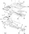
- the case 1 comprises a first 3 and a second 4 half-shell connectable to each other to define a volume housing at least one videocamera 2.
- the two half-shells 3 and 4 are hinged to each other such to be easily connected or disconnected.
- the two half-shells are preferably (but not necessarily) made of metal, for example aluminum or a preferred metal alloy and particularly at least one of them (in this example the upper half-shell 3) comprises a transparent panel 5 intended to be placed in front of the lens of the video camera such to allow it to inspect an environment to be monitored.
- the case 1 further comprises air flow generating means 7, which, in the shown example, comprise an electric fan which takes air from one side and blows it to the opposite side.
- the case 1 comprises also heating means 6 intended to raise the temperature of the air flow generated by the fan 7; in the example the heating means 6 comprise one or more heating elements arranged on a common support board (e.g. a PCB, "printed circuit board”), such to be put in a convective heat exchange condition with the air fed to the conveying duct 8 by the fan 7 and which is finally directed towards the transparent panel 5 in order to heat it and thus to prevent it from being misted up when outside of the case 1 there is a low temperature.
- a common support board e.g. a PCB, "printed circuit board
- the conveying duct 8 comprises at least one section or trunk which is characterized in that it is delimited by surrounding walls completely made of plastic material, such to isolate the air flow directed to the transparent panel and such to avoid its temperature to drop.
- the case 1 comprises a holding device 9 for the video camera 2 which is fixed to one of the two half-shells, in this example to the lower half-shell 4.
- the holding device 9 defines the surrounding walls made of plastic material of the section of the conveying duct 8.
- the holding device 9 comprises a first 91 and a second 92 body part connectable to each other in a box-like manner.
- the two parts 91 and 92 together, in the coupled condition, in this example define a first housing 93 for an electronic unit 10 controlling the video camera 2.
- the electronic unit is intended both to process the video data and to treat power, which is distributed by it to the different apparatuses (video camera, fans, heating elements etc.) inside the case 1.
- the two parts 91 and 92 in the coupled condition, define also a second housing 94 for the air flow generating means 7, that is in this example for the fan.
- the housing 94 for the air flow generating means 7 is close to the first housing 93 for an electronic unit 10 and it is in fluid communication therewith, for example by suitable openings.
- the heat produced by the electronic unit 10 can be discharged such to convey it towards the transparent panel 5 by the air flow generated by the fan.
- the section or trunk of the conveying duct 8 defined by the surrounding walls made of plastic material is formed by the coupling between the two parts 91 and 92 (in the coupled condition).
- the holding device 9 comprises also a fixing seat 95 for the heating means 6, that is for the board supporting the heating elements in this example.
- Such seat is advantageously made on the first body part 91 near one of the surrounding walls of the conveying duct 8, such to allow the air flow passing in the duct 8 to be heated.
- the enlarged opening 81 of the conveying duct 8 comprises diffusion flaps 82 arranged inside the duct 8 for distributing the air flow uniformly on the transparent panel 5.
- the first body part 91 at the enlarged opening 81 comprises a diffusion flap 83 which is tilted with respect to the transparent panel 5.
- the holding device 9 comprises a fixing plate 96 for the video camera 2.
- Such plate 96 is advantageously provided with at least one slotted hole 97 for being coupled in an adjustable way with a positioning means 11 of the video camera 2; in the example shown the positioning means 11 is a simple screw with a washer that allows the position of the video camera 2 to be adjusted and fixed in the case 1 depending on the dimensions or on the type; it has to be considered that the same case 1 can house different types of video cameras, depending on needs.
- the plate 96 with the slot 97 actually constitute a slide upon which the video camera can slide in the installation phase.
- the fixing plate 96 comprises a metal body, preferably it is entirely made of metal material, for example aluminum or a special alloy, and it is placed in contact with or in the immediate vicinity to the heating means 6 for the air flow.
- This arrangement allows an efficient heat exchange (by contact or by conduction) to be provided between the heating means 6 and the plate 96.
- the heat generated by the heating means 6, arranged in the front part of the case, is thus transferred on the whole surface of the plate 96, it being made of metal, that is a good heat conductor. Since the video camera 2 is fixed on the plate, this choice allows the video camera to be efficiently heated.
- the lower half-shell 4 has two openings with breakable baffles 20 which open when positioning the case 1 in its operating condition and which allow a certain air exchange with the outside.
- the heated air taken from the surroundings of the electronic unit 10 is conveyed into the duct 8 which avoids losses of heat by the fact that its walls are made of insulating material, such as for example plastic, a bad heat conductor.
- the air flow comes in contact with the heating elements 6, arranged in a portion of the duct placed under the plate upon which the video camera is fixed and its temperature raises.
- a desired value obtained by adjusting the power absorbed by the heating elements and by controlling the temperature by means of a sensor, e.g. a thermistor such as a PTC (Positive Temperature Coefficient).
- the air flow heated in this manner therefore comes to the opening 81 from where, thanks to the flaps 82 and 83, it is uniformly directed on the transparent panel 5, for demisting it by moisture evaporation.
- the air goes on in its path in the volume of the case, towards the rear thereof, and then it is again recovered by the fan 7 and the cycle is repeated.
- the temperature of the video camera 2 is kept at a suitable and preferred value by the fact that the plate 96 is heated due to the conduction with heating elements 6.
- the person skilled in the art can appreciate how the assembly shown in figure 4 is a holding device 9 for a surveillance video camera 2 that can be used into different types of protection cases 1.
- Such a device comprises a body comprising linking means for supporting a video camera in different relative positions with respect to the body, air flow generating means 7, and at least one electric circuit for powering and/or controlling the air flow generating means.
- the body of the device comprises a housing 94 for the air flow generating means and a housing for the electric circuit.
- the body comprises a first 91 and second 92 parts connectable to each other and such that, once coupled, define at least one section of a conveying duct 8 for an air flow.
- the duct is defined by surrounding walls made of insulating material, preferably plastic material, and extending between a first and a second end; the first end opens on the housing 94 for the air flow generating means 7, while the second end faces an end of the body opposite to the position of the housing 94 on the body itself.
- the holding device 9 further comprises heating means 6 and a seat 95 for fixing the heating means 6.
- Such fixing seat 95 is made on the first body part 91 at one of said surrounding walls of the conveying duct 8.
- the seat particularly, is placed in a position near the second end, such that it heats the air near the outlet from the duct.
- the holding device 9 preferably comprises a metal fixing plate 96 provided with a slotted hole 97 intended to receive a positioning means 11 of a video camera 2.
- the fixing plate is mounted at least partially above or in contact with the heating means 6, such that an air flow generated by the air flow generating means 7, flowing through the heating means comes in contact with the fixing plate.
Landscapes
- Physics & Mathematics (AREA)
- General Physics & Mathematics (AREA)
- Engineering & Computer Science (AREA)
- Aviation & Aerospace Engineering (AREA)
- Multimedia (AREA)
- Signal Processing (AREA)
- Studio Devices (AREA)
- Accessories Of Cameras (AREA)
- Packages (AREA)
Priority Applications (3)
| Application Number | Priority Date | Filing Date | Title |
|---|---|---|---|
| SI201330263A SI2898488T1 (sl) | 2012-09-24 | 2013-09-12 | Izboljšana škatla za nadzorno video kamero in držalna naprava za škatlo za nadzorno video kamero |
| RS20160636A RS54996B1 (sr) | 2012-09-24 | 2013-09-12 | Poboljšano kućište za kameru za video nadzor i nosač za kućište za kameru za video nadzor |
| HRP20160979TT HRP20160979T1 (hr) | 2012-09-24 | 2016-08-01 | Poboljšano kućište za nadzornu videokameru i uređaj za držanje kućišta nadzorne videokamere |
Applications Claiming Priority (2)
| Application Number | Priority Date | Filing Date | Title |
|---|---|---|---|
| IT001589A ITMI20121589A1 (it) | 2012-09-24 | 2012-09-24 | Custodia perfezionata per videocamera di sorveglianza e dispositivo di supporto per una custodia per videocamera di sorveglianza |
| PCT/IB2013/058504 WO2014045170A1 (en) | 2012-09-24 | 2013-09-12 | Improved case for surveillance video camera and holding device for a case for a surveillance video camera |
Publications (2)
| Publication Number | Publication Date |
|---|---|
| EP2898488A1 EP2898488A1 (en) | 2015-07-29 |
| EP2898488B1 true EP2898488B1 (en) | 2016-07-13 |
Family
ID=47046699
Family Applications (1)
| Application Number | Title | Priority Date | Filing Date |
|---|---|---|---|
| EP13801726.4A Active EP2898488B1 (en) | 2012-09-24 | 2013-09-12 | Improved case for surveillance video camera and holding device for a case for a surveillance video camera |
Country Status (23)
| Country | Link |
|---|---|
| US (1) | US9392149B2 (pt) |
| EP (1) | EP2898488B1 (pt) |
| JP (1) | JP6208242B2 (pt) |
| KR (1) | KR102020701B1 (pt) |
| CN (1) | CN104871222B (pt) |
| BR (1) | BR112015006108A2 (pt) |
| CA (1) | CA2885999C (pt) |
| DK (1) | DK2898488T3 (pt) |
| EA (1) | EA030171B1 (pt) |
| ES (1) | ES2586634T3 (pt) |
| HK (1) | HK1208282A1 (pt) |
| HR (1) | HRP20160979T1 (pt) |
| HU (1) | HUE029270T2 (pt) |
| IL (1) | IL237805B (pt) |
| IN (1) | IN2015DN02995A (pt) |
| IT (1) | ITMI20121589A1 (pt) |
| PL (1) | PL2898488T3 (pt) |
| PT (1) | PT2898488T (pt) |
| RS (1) | RS54996B1 (pt) |
| SA (1) | SA515360176B1 (pt) |
| SG (1) | SG11201502007YA (pt) |
| SI (1) | SI2898488T1 (pt) |
| WO (1) | WO2014045170A1 (pt) |
Families Citing this family (8)
| Publication number | Priority date | Publication date | Assignee | Title |
|---|---|---|---|---|
| USD835697S1 (en) | 2015-03-16 | 2018-12-11 | Axis Ab | Monitoring camera |
| CN105159012B (zh) * | 2015-08-19 | 2017-10-24 | 常州精华数控设备有限公司 | Ccd摄像机镜头保护装置 |
| JP6652305B2 (ja) * | 2016-04-28 | 2020-02-19 | キヤノン株式会社 | 撮像装置、及び画像監視システム |
| JP6401764B2 (ja) * | 2016-10-20 | 2018-10-10 | 株式会社アマダホールディングス | 火災発生検出カメラ |
| CN109194850A (zh) * | 2018-08-22 | 2019-01-11 | 黄荣济 | 户外健身器材监控设备 |
| CN109803075B (zh) * | 2019-01-16 | 2020-12-18 | 赣州金宁保安服务有限公司 | 一种热成像安全防盗的监控设备 |
| US11474417B2 (en) | 2020-08-07 | 2022-10-18 | Lineage Logistics, LLC | Lens heater assembly for camera |
| RU208588U1 (ru) * | 2021-06-25 | 2021-12-24 | Общество с ограниченной ответственностью "Консалтинг" | Камера видеонаблюдения |
Family Cites Families (20)
| Publication number | Priority date | Publication date | Assignee | Title |
|---|---|---|---|---|
| US4414576A (en) * | 1981-09-25 | 1983-11-08 | Vicon Industries, Inc. | Housing assembly for electrical apparatus |
| KR930001232Y1 (ko) * | 1990-12-21 | 1993-03-22 | 김부길 | 원적외선 바이오 세라믹 피부 맛사지기 |
| JPH04247421A (ja) * | 1991-02-01 | 1992-09-03 | Matsushita Electric Ind Co Ltd | レンズの曇り防止装置 |
| US5394184A (en) * | 1993-08-30 | 1995-02-28 | Sensormatic Electronics Corporation | Surveillance assembly having circumferential delivery of forced air to viewing bubble |
| US5689304A (en) * | 1996-03-04 | 1997-11-18 | Philips Electronic North America Corporation | Indoor/outdoor surveillance housing |
| US6061087A (en) * | 1998-07-16 | 2000-05-09 | Sensormatic Electronics Corporation | Outdoor enclosure for video surveillance system |
| JP2002040554A (ja) * | 2000-07-25 | 2002-02-06 | Fuji Photo Optical Co Ltd | カメラハウジングの空気調和装置 |
| JP2004258293A (ja) * | 2003-02-26 | 2004-09-16 | Japan Aviation Electronics Industry Ltd | スタビライザ付カメラ |
| CA2438939C (en) * | 2003-08-28 | 2008-11-18 | Jack Gin | Dual surveillance camera system |
| JP4514525B2 (ja) * | 2004-06-11 | 2010-07-28 | パナソニック株式会社 | カメラ装置 |
| CN100464248C (zh) * | 2006-04-04 | 2009-02-25 | 潘国平 | 具有自洁功能的球形摄像机云台 |
| EP1883226A3 (en) * | 2006-07-28 | 2008-05-07 | Videotec S.P.A. | Closed-circuit telecamera housing (cctv) |
| US7857527B2 (en) * | 2008-09-12 | 2010-12-28 | Pelco, Inc. | Hinged camera sled |
| EP2184963B1 (en) * | 2008-11-06 | 2011-10-05 | Axis AB | Housing for electronic device. |
| JP5649363B2 (ja) * | 2010-08-03 | 2015-01-07 | キヤノン株式会社 | ドーム型カメラ |
| KR101665390B1 (ko) * | 2011-01-12 | 2016-10-12 | 한화테크윈 주식회사 | 하우징 조립체 |
| US20130062228A1 (en) * | 2011-09-09 | 2013-03-14 | Zakrytoe Aktsionernoe Obshchestvo "STREAM Labs" | Method for prevention of pollution of the glass of the front window of a housing for an outdoor surveillance camera and a housing for implementation of this method |
| SE538424C2 (sv) * | 2011-09-20 | 2016-06-21 | Drs Network & Imaging Systems Llc | Värmeisoleringsanordning för IR-övervakningskamera |
| CN202424859U (zh) * | 2011-12-27 | 2012-09-05 | 宁波凯必世电子有限公司 | 一种可在严寒环境中运行的监控摄像机防护罩 |
| TWM480697U (zh) * | 2013-10-25 | 2014-06-21 | Lontrend Corp | 具有調溫功能之攝影機防護裝置 |
-
2012
- 2012-09-24 IT IT001589A patent/ITMI20121589A1/it unknown
-
2013
- 2013-09-12 WO PCT/IB2013/058504 patent/WO2014045170A1/en active Application Filing
- 2013-09-12 KR KR1020157007487A patent/KR102020701B1/ko active IP Right Grant
- 2013-09-12 EA EA201590635A patent/EA030171B1/ru not_active IP Right Cessation
- 2013-09-12 PL PL13801726.4T patent/PL2898488T3/pl unknown
- 2013-09-12 IN IN2995DEN2015 patent/IN2015DN02995A/en unknown
- 2013-09-12 ES ES13801726.4T patent/ES2586634T3/es active Active
- 2013-09-12 CN CN201380049633.5A patent/CN104871222B/zh not_active Expired - Fee Related
- 2013-09-12 EP EP13801726.4A patent/EP2898488B1/en active Active
- 2013-09-12 BR BR112015006108A patent/BR112015006108A2/pt not_active Application Discontinuation
- 2013-09-12 US US14/430,830 patent/US9392149B2/en active Active
- 2013-09-12 SG SG11201502007YA patent/SG11201502007YA/en unknown
- 2013-09-12 DK DK13801726.4T patent/DK2898488T3/en active
- 2013-09-12 PT PT138017264T patent/PT2898488T/pt unknown
- 2013-09-12 JP JP2015532547A patent/JP6208242B2/ja not_active Expired - Fee Related
- 2013-09-12 RS RS20160636A patent/RS54996B1/sr unknown
- 2013-09-12 CA CA2885999A patent/CA2885999C/en not_active Expired - Fee Related
- 2013-09-12 HU HUE13801726A patent/HUE029270T2/en unknown
- 2013-09-12 SI SI201330263A patent/SI2898488T1/sl unknown
-
2015
- 2015-03-18 IL IL237805A patent/IL237805B/en active IP Right Grant
- 2015-03-22 SA SA515360176A patent/SA515360176B1/ar unknown
- 2015-09-14 HK HK15108957.7A patent/HK1208282A1/zh not_active IP Right Cessation
-
2016
- 2016-08-01 HR HRP20160979TT patent/HRP20160979T1/hr unknown
Also Published As
| Publication number | Publication date |
|---|---|
| SA515360176B1 (ar) | 2016-09-18 |
| US20150264228A1 (en) | 2015-09-17 |
| PL2898488T3 (pl) | 2016-11-30 |
| IN2015DN02995A (pt) | 2015-10-02 |
| EP2898488A1 (en) | 2015-07-29 |
| CN104871222B (zh) | 2017-06-30 |
| JP6208242B2 (ja) | 2017-10-04 |
| HRP20160979T1 (hr) | 2016-10-07 |
| BR112015006108A2 (pt) | 2017-07-04 |
| HK1208282A1 (zh) | 2016-02-26 |
| CN104871222A (zh) | 2015-08-26 |
| HUE029270T2 (en) | 2017-02-28 |
| CA2885999C (en) | 2021-01-12 |
| ITMI20121589A1 (it) | 2014-03-25 |
| PT2898488T (pt) | 2016-08-16 |
| RS54996B1 (sr) | 2016-11-30 |
| WO2014045170A1 (en) | 2014-03-27 |
| JP2015534118A (ja) | 2015-11-26 |
| CA2885999A1 (en) | 2014-03-27 |
| KR102020701B1 (ko) | 2019-09-10 |
| SG11201502007YA (en) | 2015-05-28 |
| EA201590635A1 (ru) | 2015-11-30 |
| DK2898488T3 (en) | 2016-08-22 |
| US9392149B2 (en) | 2016-07-12 |
| SI2898488T1 (sl) | 2016-09-30 |
| IL237805B (en) | 2018-01-31 |
| KR20150063394A (ko) | 2015-06-09 |
| ES2586634T3 (es) | 2016-10-17 |
| EA030171B1 (ru) | 2018-06-29 |
Similar Documents
| Publication | Publication Date | Title |
|---|---|---|
| EP2898488B1 (en) | Improved case for surveillance video camera and holding device for a case for a surveillance video camera | |
| KR101118563B1 (ko) | 전기 배전함 및 통신함 설치용 냉온유지장치 | |
| US7347058B2 (en) | Vent for a data center cooling system | |
| US20190313001A1 (en) | Monitoring camera and condensation suppressing method | |
| NL1029970C1 (nl) | Voeding met een koelfunctie. | |
| US20020139554A1 (en) | Electric system with safety device against spread of fire occurred inside casing | |
| US10451295B2 (en) | Equipment enclosure with multi-mode temperature control system | |
| US20090061758A1 (en) | Floor Vent Booster Fan | |
| EP2928276B1 (en) | Cooling flow optimization | |
| JP2010273459A (ja) | ヒーターユニット | |
| EP2026496B1 (en) | Protection case for cameras which are capable of transmitting a digital video signal | |
| CN210181374U (zh) | 一种投影机智能恒温恒湿防护箱 | |
| KR101950348B1 (ko) | 방열 기능이 우수한 전원 원격제어 함체 | |
| US10072881B2 (en) | Reduced footprint thermoelectric cooler controller | |
| JP3581489B2 (ja) | 浴室暖房乾燥機 | |
| JP2004060904A (ja) | 浴室暖房装置 | |
| KR102491001B1 (ko) | 제어반용 열교환시스템과 열교환시스템이 구비된 제어반 그리고 열교환시스템용 냉매조성물 | |
| US20020015286A1 (en) | Temperature regulation apparatus for electrical box | |
| WO2002103505A2 (en) | Cooling element and method for pc cpu and/or hot side of thermo electric cooler heat sink | |
| JP4271867B2 (ja) | ケーブルコネクタ | |
| JP3688599B2 (ja) | プリント基板 | |
| WO2017059443A1 (en) | Reduced footprint thermoelectric cooler controller | |
| US20090078691A1 (en) | Room temperature raising apparatus | |
| JP2003079014A (ja) | ヒーターユニット | |
| JP2001085867A (ja) | 屋外装置の気密の確保方法およびその装置 |
Legal Events
| Date | Code | Title | Description |
|---|---|---|---|
| PUAI | Public reference made under article 153(3) epc to a published international application that has entered the european phase |
Free format text: ORIGINAL CODE: 0009012 |
|
| 17P | Request for examination filed |
Effective date: 20150313 |
|
| AK | Designated contracting states |
Kind code of ref document: A1 Designated state(s): AL AT BE BG CH CY CZ DE DK EE ES FI FR GB GR HR HU IE IS IT LI LT LU LV MC MK MT NL NO PL PT RO RS SE SI SK SM TR |
|
| AX | Request for extension of the european patent |
Extension state: BA ME |
|
| REG | Reference to a national code |
Ref country code: HK Ref legal event code: DE Ref document number: 1208282 Country of ref document: HK |
|
| GRAP | Despatch of communication of intention to grant a patent |
Free format text: ORIGINAL CODE: EPIDOSNIGR1 |
|
| RIN1 | Information on inventor provided before grant (corrected) |
Inventor name: ZATTARA, DARIO Inventor name: GROTTO, ALESSIO |
|
| INTG | Intention to grant announced |
Effective date: 20160302 |
|
| GRAS | Grant fee paid |
Free format text: ORIGINAL CODE: EPIDOSNIGR3 |
|
| GRAA | (expected) grant |
Free format text: ORIGINAL CODE: 0009210 |
|
| AK | Designated contracting states |
Kind code of ref document: B1 Designated state(s): AL AT BE BG CH CY CZ DE DK EE ES FI FR GB GR HR HU IE IS IT LI LT LU LV MC MK MT NL NO PL PT RO RS SE SI SK SM TR |
|
| AX | Request for extension of the european patent |
Extension state: BA ME |
|
| REG | Reference to a national code |
Ref country code: GB Ref legal event code: FG4D |
|
| REG | Reference to a national code |
Ref country code: AT Ref legal event code: REF Ref document number: 812861 Country of ref document: AT Kind code of ref document: T Effective date: 20160715 Ref country code: CH Ref legal event code: EP |
|
| REG | Reference to a national code |
Ref country code: HR Ref legal event code: TUEP Ref document number: P20160979 Country of ref document: HR |
|
| REG | Reference to a national code |
Ref country code: RO Ref legal event code: EPE |
|
| REG | Reference to a national code |
Ref country code: IE Ref legal event code: FG4D |
|
| REG | Reference to a national code |
Ref country code: PT Ref legal event code: SC4A Ref document number: 2898488 Country of ref document: PT Date of ref document: 20160816 Kind code of ref document: T Free format text: AVAILABILITY OF NATIONAL TRANSLATION Effective date: 20160808 |
|
| REG | Reference to a national code |
Ref country code: DK Ref legal event code: T3 Effective date: 20160818 |
|
| REG | Reference to a national code |
Ref country code: DE Ref legal event code: R096 Ref document number: 602013009454 Country of ref document: DE |
|
| REG | Reference to a national code |
Ref country code: SE Ref legal event code: TRGR |
|
| REG | Reference to a national code |
Ref country code: NL Ref legal event code: FP |
|
| REG | Reference to a national code |
Ref country code: FR Ref legal event code: PLFP Year of fee payment: 4 |
|
| REG | Reference to a national code |
Ref country code: HR Ref legal event code: T1PR Ref document number: P20160979 Country of ref document: HR |
|
| REG | Reference to a national code |
Ref country code: EE Ref legal event code: FG4A Ref document number: E012403 Country of ref document: EE Effective date: 20160803 Ref country code: ES Ref legal event code: FG2A Ref document number: 2586634 Country of ref document: ES Kind code of ref document: T3 Effective date: 20161017 |
|
| REG | Reference to a national code |
Ref country code: NO Ref legal event code: T2 Effective date: 20160713 |
|
| PG25 | Lapsed in a contracting state [announced via postgrant information from national office to epo] |
Ref country code: IS Free format text: LAPSE BECAUSE OF FAILURE TO SUBMIT A TRANSLATION OF THE DESCRIPTION OR TO PAY THE FEE WITHIN THE PRESCRIBED TIME-LIMIT Effective date: 20161113 |
|
| PG25 | Lapsed in a contracting state [announced via postgrant information from national office to epo] |
Ref country code: GR Free format text: LAPSE BECAUSE OF FAILURE TO SUBMIT A TRANSLATION OF THE DESCRIPTION OR TO PAY THE FEE WITHIN THE PRESCRIBED TIME-LIMIT Effective date: 20161014 |
|
| REG | Reference to a national code |
Ref country code: HU Ref legal event code: AG4A Ref document number: E029270 Country of ref document: HU |
|
| REG | Reference to a national code |
Ref country code: HK Ref legal event code: GR Ref document number: 1208282 Country of ref document: HK |
|
| REG | Reference to a national code |
Ref country code: DE Ref legal event code: R097 Ref document number: 602013009454 Country of ref document: DE |
|
| PG25 | Lapsed in a contracting state [announced via postgrant information from national office to epo] |
Ref country code: MC Free format text: LAPSE BECAUSE OF FAILURE TO SUBMIT A TRANSLATION OF THE DESCRIPTION OR TO PAY THE FEE WITHIN THE PRESCRIBED TIME-LIMIT Effective date: 20160713 |
|
| PLBE | No opposition filed within time limit |
Free format text: ORIGINAL CODE: 0009261 |
|
| STAA | Information on the status of an ep patent application or granted ep patent |
Free format text: STATUS: NO OPPOSITION FILED WITHIN TIME LIMIT |
|
| PG25 | Lapsed in a contracting state [announced via postgrant information from national office to epo] |
Ref country code: BG Free format text: LAPSE BECAUSE OF FAILURE TO SUBMIT A TRANSLATION OF THE DESCRIPTION OR TO PAY THE FEE WITHIN THE PRESCRIBED TIME-LIMIT Effective date: 20161013 Ref country code: SM Free format text: LAPSE BECAUSE OF FAILURE TO SUBMIT A TRANSLATION OF THE DESCRIPTION OR TO PAY THE FEE WITHIN THE PRESCRIBED TIME-LIMIT Effective date: 20160713 |
|
| 26N | No opposition filed |
Effective date: 20170418 |
|
| REG | Reference to a national code |
Ref country code: FR Ref legal event code: PLFP Year of fee payment: 5 |
|
| PG25 | Lapsed in a contracting state [announced via postgrant information from national office to epo] |
Ref country code: MT Free format text: LAPSE BECAUSE OF NON-PAYMENT OF DUE FEES Effective date: 20160930 Ref country code: CY Free format text: LAPSE BECAUSE OF FAILURE TO SUBMIT A TRANSLATION OF THE DESCRIPTION OR TO PAY THE FEE WITHIN THE PRESCRIBED TIME-LIMIT Effective date: 20160713 Ref country code: MK Free format text: LAPSE BECAUSE OF FAILURE TO SUBMIT A TRANSLATION OF THE DESCRIPTION OR TO PAY THE FEE WITHIN THE PRESCRIBED TIME-LIMIT Effective date: 20160713 |
|
| REG | Reference to a national code |
Ref country code: FR Ref legal event code: PLFP Year of fee payment: 6 |
|
| PG25 | Lapsed in a contracting state [announced via postgrant information from national office to epo] |
Ref country code: AL Free format text: LAPSE BECAUSE OF FAILURE TO SUBMIT A TRANSLATION OF THE DESCRIPTION OR TO PAY THE FEE WITHIN THE PRESCRIBED TIME-LIMIT Effective date: 20160713 |
|
| REG | Reference to a national code |
Ref country code: HR Ref legal event code: ODRP Ref document number: P20160979 Country of ref document: HR Payment date: 20190828 Year of fee payment: 7 |
|
| PGFP | Annual fee paid to national office [announced via postgrant information from national office to epo] |
Ref country code: IE Payment date: 20190925 Year of fee payment: 7 Ref country code: TR Payment date: 20190910 Year of fee payment: 7 Ref country code: DK Payment date: 20190925 Year of fee payment: 7 Ref country code: RO Payment date: 20190830 Year of fee payment: 7 Ref country code: SI Payment date: 20190828 Year of fee payment: 7 Ref country code: NO Payment date: 20190927 Year of fee payment: 7 Ref country code: CZ Payment date: 20190828 Year of fee payment: 7 Ref country code: EE Payment date: 20190927 Year of fee payment: 7 Ref country code: LT Payment date: 20190827 Year of fee payment: 7 Ref country code: LU Payment date: 20190925 Year of fee payment: 7 Ref country code: PT Payment date: 20190823 Year of fee payment: 7 Ref country code: SK Payment date: 20190827 Year of fee payment: 7 Ref country code: FI Payment date: 20190926 Year of fee payment: 7 Ref country code: SE Payment date: 20190925 Year of fee payment: 7 |
|
| PGFP | Annual fee paid to national office [announced via postgrant information from national office to epo] |
Ref country code: BE Payment date: 20190925 Year of fee payment: 7 Ref country code: RS Payment date: 20190826 Year of fee payment: 7 Ref country code: HU Payment date: 20190903 Year of fee payment: 7 Ref country code: PL Payment date: 20190826 Year of fee payment: 7 Ref country code: HR Payment date: 20190828 Year of fee payment: 7 Ref country code: LV Payment date: 20190927 Year of fee payment: 7 |
|
| PGFP | Annual fee paid to national office [announced via postgrant information from national office to epo] |
Ref country code: AT Payment date: 20190926 Year of fee payment: 7 |
|
| PGFP | Annual fee paid to national office [announced via postgrant information from national office to epo] |
Ref country code: CH Payment date: 20190925 Year of fee payment: 7 |
|
| PGFP | Annual fee paid to national office [announced via postgrant information from national office to epo] |
Ref country code: ES Payment date: 20191009 Year of fee payment: 7 |
|
| PGFP | Annual fee paid to national office [announced via postgrant information from national office to epo] |
Ref country code: NL Payment date: 20200924 Year of fee payment: 8 Ref country code: FR Payment date: 20200925 Year of fee payment: 8 Ref country code: GB Payment date: 20200924 Year of fee payment: 8 Ref country code: DE Payment date: 20200923 Year of fee payment: 8 |
|
| PGFP | Annual fee paid to national office [announced via postgrant information from national office to epo] |
Ref country code: IT Payment date: 20200930 Year of fee payment: 8 |
|
| REG | Reference to a national code |
Ref country code: HR Ref legal event code: PBON Ref document number: P20160979 Country of ref document: HR Effective date: 20200912 |
|
| REG | Reference to a national code |
Ref country code: EE Ref legal event code: MM4A Ref document number: E012403 Country of ref document: EE Effective date: 20200930 Ref country code: FI Ref legal event code: MAE |
|
| REG | Reference to a national code |
Ref country code: NO Ref legal event code: MMEP Ref country code: DK Ref legal event code: EBP Effective date: 20200930 |
|
| PG25 | Lapsed in a contracting state [announced via postgrant information from national office to epo] |
Ref country code: RO Free format text: LAPSE BECAUSE OF NON-PAYMENT OF DUE FEES Effective date: 20200912 Ref country code: FI Free format text: LAPSE BECAUSE OF NON-PAYMENT OF DUE FEES Effective date: 20200912 Ref country code: CZ Free format text: LAPSE BECAUSE OF NON-PAYMENT OF DUE FEES Effective date: 20200912 |
|
| REG | Reference to a national code |
Ref country code: CH Ref legal event code: PL |
|
| REG | Reference to a national code |
Ref country code: AT Ref legal event code: MM01 Ref document number: 812861 Country of ref document: AT Kind code of ref document: T Effective date: 20200912 |
|
| REG | Reference to a national code |
Ref country code: SK Ref legal event code: MM4A Ref document number: E 21663 Country of ref document: SK Effective date: 20200912 |
|
| PG25 | Lapsed in a contracting state [announced via postgrant information from national office to epo] |
Ref country code: RS Free format text: LAPSE BECAUSE OF NON-PAYMENT OF DUE FEES Effective date: 20200912 Ref country code: LV Free format text: LAPSE BECAUSE OF NON-PAYMENT OF DUE FEES Effective date: 20200912 |
|
| REG | Reference to a national code |
Ref country code: BE Ref legal event code: MM Effective date: 20200930 |
|
| PG25 | Lapsed in a contracting state [announced via postgrant information from national office to epo] |
Ref country code: LU Free format text: LAPSE BECAUSE OF NON-PAYMENT OF DUE FEES Effective date: 20200912 |
|
| PG25 | Lapsed in a contracting state [announced via postgrant information from national office to epo] |
Ref country code: HR Free format text: LAPSE BECAUSE OF NON-PAYMENT OF DUE FEES Effective date: 20200912 Ref country code: SK Free format text: LAPSE BECAUSE OF NON-PAYMENT OF DUE FEES Effective date: 20200912 Ref country code: PT Free format text: LAPSE BECAUSE OF NON-PAYMENT OF DUE FEES Effective date: 20210413 Ref country code: EE Free format text: LAPSE BECAUSE OF NON-PAYMENT OF DUE FEES Effective date: 20200930 Ref country code: NO Free format text: LAPSE BECAUSE OF NON-PAYMENT OF DUE FEES Effective date: 20200930 |
|
| REG | Reference to a national code |
Ref country code: LT Ref legal event code: MM4D Effective date: 20200912 |
|
| PG25 | Lapsed in a contracting state [announced via postgrant information from national office to epo] |
Ref country code: AT Free format text: LAPSE BECAUSE OF NON-PAYMENT OF DUE FEES Effective date: 20200912 Ref country code: CH Free format text: LAPSE BECAUSE OF NON-PAYMENT OF DUE FEES Effective date: 20200930 Ref country code: BE Free format text: LAPSE BECAUSE OF NON-PAYMENT OF DUE FEES Effective date: 20200930 Ref country code: LI Free format text: LAPSE BECAUSE OF NON-PAYMENT OF DUE FEES Effective date: 20200930 Ref country code: HU Free format text: LAPSE BECAUSE OF NON-PAYMENT OF DUE FEES Effective date: 20200913 Ref country code: IE Free format text: LAPSE BECAUSE OF NON-PAYMENT OF DUE FEES Effective date: 20200912 Ref country code: SE Free format text: LAPSE BECAUSE OF NON-PAYMENT OF DUE FEES Effective date: 20200913 Ref country code: SI Free format text: LAPSE BECAUSE OF NON-PAYMENT OF DUE FEES Effective date: 20200913 |
|
| REG | Reference to a national code |
Ref country code: SI Ref legal event code: KO00 Effective date: 20210811 |
|
| REG | Reference to a national code |
Ref country code: SE Ref legal event code: EUG |
|
| PG25 | Lapsed in a contracting state [announced via postgrant information from national office to epo] |
Ref country code: LT Free format text: LAPSE BECAUSE OF NON-PAYMENT OF DUE FEES Effective date: 20200912 |
|
| PG25 | Lapsed in a contracting state [announced via postgrant information from national office to epo] |
Ref country code: DK Free format text: LAPSE BECAUSE OF NON-PAYMENT OF DUE FEES Effective date: 20200930 |
|
| REG | Reference to a national code |
Ref country code: ES Ref legal event code: FD2A Effective date: 20220117 |
|
| REG | Reference to a national code |
Ref country code: DE Ref legal event code: R119 Ref document number: 602013009454 Country of ref document: DE |
|
| REG | Reference to a national code |
Ref country code: NL Ref legal event code: MM Effective date: 20211001 |
|
| GBPC | Gb: european patent ceased through non-payment of renewal fee |
Effective date: 20210912 |
|
| PG25 | Lapsed in a contracting state [announced via postgrant information from national office to epo] |
Ref country code: ES Free format text: LAPSE BECAUSE OF NON-PAYMENT OF DUE FEES Effective date: 20200913 |
|
| PG25 | Lapsed in a contracting state [announced via postgrant information from national office to epo] |
Ref country code: TR Free format text: LAPSE BECAUSE OF NON-PAYMENT OF DUE FEES Effective date: 20200912 Ref country code: NL Free format text: LAPSE BECAUSE OF NON-PAYMENT OF DUE FEES Effective date: 20211001 |
|
| PG25 | Lapsed in a contracting state [announced via postgrant information from national office to epo] |
Ref country code: GB Free format text: LAPSE BECAUSE OF NON-PAYMENT OF DUE FEES Effective date: 20210912 Ref country code: FR Free format text: LAPSE BECAUSE OF NON-PAYMENT OF DUE FEES Effective date: 20210930 Ref country code: DE Free format text: LAPSE BECAUSE OF NON-PAYMENT OF DUE FEES Effective date: 20220401 |
|
| PG25 | Lapsed in a contracting state [announced via postgrant information from national office to epo] |
Ref country code: IT Free format text: LAPSE BECAUSE OF NON-PAYMENT OF DUE FEES Effective date: 20210912 |
|
| PG25 | Lapsed in a contracting state [announced via postgrant information from national office to epo] |
Ref country code: PL Free format text: LAPSE BECAUSE OF NON-PAYMENT OF DUE FEES Effective date: 20200912 |