EP2898110B1 - Vorrichtung zum beschichten eines substrats aus teilchen - Google Patents
Vorrichtung zum beschichten eines substrats aus teilchen Download PDFInfo
- Publication number
- EP2898110B1 EP2898110B1 EP13791899.1A EP13791899A EP2898110B1 EP 2898110 B1 EP2898110 B1 EP 2898110B1 EP 13791899 A EP13791899 A EP 13791899A EP 2898110 B1 EP2898110 B1 EP 2898110B1
- Authority
- EP
- European Patent Office
- Prior art keywords
- substrate
- plate
- shell
- dish
- substrate dish
- Prior art date
- Legal status (The legal status is an assumption and is not a legal conclusion. Google has not performed a legal analysis and makes no representation as to the accuracy of the status listed.)
- Active
Links
Images


Classifications
-
- C—CHEMISTRY; METALLURGY
- C23—COATING METALLIC MATERIAL; COATING MATERIAL WITH METALLIC MATERIAL; CHEMICAL SURFACE TREATMENT; DIFFUSION TREATMENT OF METALLIC MATERIAL; COATING BY VACUUM EVAPORATION, BY SPUTTERING, BY ION IMPLANTATION OR BY CHEMICAL VAPOUR DEPOSITION, IN GENERAL; INHIBITING CORROSION OF METALLIC MATERIAL OR INCRUSTATION IN GENERAL
- C23C—COATING METALLIC MATERIAL; COATING MATERIAL WITH METALLIC MATERIAL; SURFACE TREATMENT OF METALLIC MATERIAL BY DIFFUSION INTO THE SURFACE, BY CHEMICAL CONVERSION OR SUBSTITUTION; COATING BY VACUUM EVAPORATION, BY SPUTTERING, BY ION IMPLANTATION OR BY CHEMICAL VAPOUR DEPOSITION, IN GENERAL
- C23C14/00—Coating by vacuum evaporation, by sputtering or by ion implantation of the coating forming material
- C23C14/22—Coating by vacuum evaporation, by sputtering or by ion implantation of the coating forming material characterised by the process of coating
- C23C14/50—Substrate holders
- C23C14/505—Substrate holders for rotation of the substrates
-
- C—CHEMISTRY; METALLURGY
- C23—COATING METALLIC MATERIAL; COATING MATERIAL WITH METALLIC MATERIAL; CHEMICAL SURFACE TREATMENT; DIFFUSION TREATMENT OF METALLIC MATERIAL; COATING BY VACUUM EVAPORATION, BY SPUTTERING, BY ION IMPLANTATION OR BY CHEMICAL VAPOUR DEPOSITION, IN GENERAL; INHIBITING CORROSION OF METALLIC MATERIAL OR INCRUSTATION IN GENERAL
- C23C—COATING METALLIC MATERIAL; COATING MATERIAL WITH METALLIC MATERIAL; SURFACE TREATMENT OF METALLIC MATERIAL BY DIFFUSION INTO THE SURFACE, BY CHEMICAL CONVERSION OR SUBSTITUTION; COATING BY VACUUM EVAPORATION, BY SPUTTERING, BY ION IMPLANTATION OR BY CHEMICAL VAPOUR DEPOSITION, IN GENERAL
- C23C14/00—Coating by vacuum evaporation, by sputtering or by ion implantation of the coating forming material
- C23C14/22—Coating by vacuum evaporation, by sputtering or by ion implantation of the coating forming material characterised by the process of coating
- C23C14/223—Coating by vacuum evaporation, by sputtering or by ion implantation of the coating forming material characterised by the process of coating specially adapted for coating particles
-
- C—CHEMISTRY; METALLURGY
- C23—COATING METALLIC MATERIAL; COATING MATERIAL WITH METALLIC MATERIAL; CHEMICAL SURFACE TREATMENT; DIFFUSION TREATMENT OF METALLIC MATERIAL; COATING BY VACUUM EVAPORATION, BY SPUTTERING, BY ION IMPLANTATION OR BY CHEMICAL VAPOUR DEPOSITION, IN GENERAL; INHIBITING CORROSION OF METALLIC MATERIAL OR INCRUSTATION IN GENERAL
- C23C—COATING METALLIC MATERIAL; COATING MATERIAL WITH METALLIC MATERIAL; SURFACE TREATMENT OF METALLIC MATERIAL BY DIFFUSION INTO THE SURFACE, BY CHEMICAL CONVERSION OR SUBSTITUTION; COATING BY VACUUM EVAPORATION, BY SPUTTERING, BY ION IMPLANTATION OR BY CHEMICAL VAPOUR DEPOSITION, IN GENERAL
- C23C14/00—Coating by vacuum evaporation, by sputtering or by ion implantation of the coating forming material
- C23C14/22—Coating by vacuum evaporation, by sputtering or by ion implantation of the coating forming material characterised by the process of coating
- C23C14/34—Sputtering
-
- H—ELECTRICITY
- H01—ELECTRIC ELEMENTS
- H01J—ELECTRIC DISCHARGE TUBES OR DISCHARGE LAMPS
- H01J37/00—Discharge tubes with provision for introducing objects or material to be exposed to the discharge, e.g. for the purpose of examination or processing thereof
- H01J37/32—Gas-filled discharge tubes
- H01J37/34—Gas-filled discharge tubes operating with cathodic sputtering
- H01J37/3411—Constructional aspects of the reactor
- H01J37/3435—Target holders (includes backing plates and endblocks)
-
- H—ELECTRICITY
- H01—ELECTRIC ELEMENTS
- H01J—ELECTRIC DISCHARGE TUBES OR DISCHARGE LAMPS
- H01J2237/00—Discharge tubes exposing object to beam, e.g. for analysis treatment, etching, imaging
- H01J2237/32—Processing objects by plasma generation
- H01J2237/33—Processing objects by plasma generation characterised by the type of processing
- H01J2237/332—Coating
- H01J2237/3322—Problems associated with coating
- H01J2237/3323—Problems associated with coating uniformity
Definitions
- the invention relates to a device for coating a substrate of particles, such as grains, granules, powders, slices, rods or fibers, by means of cathode sputtering with a movable, against the horizontal plane inclined substrate shell.
- particles such as grains, granules, powders, slices, rods or fibers
- the process of sputtering is a method for non-destructive coating, for example of powdery or granular substrates.
- the most common variations to achieve the most uniform possible coating of a substrate are spin coating, hollow cathode coating and rod cathode coating.
- spin coating is due to the necessary high gas flows, the use in conjunction with cathode sputtering limited.
- the hollow cathode coating the supply and discharge of the substrate, which falls through a vertically arranged hollow cylindrical cathode, difficulties.
- the rod cathode coating in which the substrate is in a rotating about a horizontal axis of rotation drum, in the middle of the rod cathode is arranged , only low coating rates are possible.
- a device of the type mentioned, which allows a comparison with the known methods improved coating has already been G. Schmid et al., "Optimization of a container design for depositing uniform metal coatings on glass microspheres by magnetron sputtering", Surface & Coatings Technology 205 (2010) pp. 1929-1936 , described.
- the device is based on the per se known technique of magnetron sputtering, wherein in addition to the (in the cathode sputtering obvious) electric field, a magnetic field is arranged so that the charge carriers in spiral paths over the target surface and thus a higher ionization and ultimately a higher sputtering rate is achieved.
- an inclined substrate shell is arranged opposite and below the target.
- the contained substrate By rotating the substrate shell, the contained substrate is mixed and a Sticking the particles against each other or with the container wall counteracted.
- the coating of glass microspheres tested in the cited article is particularly demanding, since the hollow glass spheres are on the one hand mechanically sensitive and generally small particles - due to the low density tend more strongly to sticking than other, for example, massive, substrates.
- the US 6,355,146 shows a coating method using magnetron sputtering, wherein a substrate shell is either vibrated by means of piezoelectric elements or rotated in the manner of a paddle wheel.
- the US Pat. No. 6,038,999 A1 shows a coating device with a tilted by 15 ° receiving chamber for a loose parts existing substrate. Shaking of the substrate is achieved by the rotation of the chamber and optionally by additional stirring rods.
- the in JP 11241157 A shown substrate container rotates about an inclined axis and includes a screen or a basket which is immovably connected to the container. Blending of the substrate is achieved by interrupting and reversing the rotational motion.
- a piezoelectric vibrator with a shell is known in which particles to be coated are placed, the vibrator being arranged on a pivotable plate.
- GB 2 282 824 A an arrangement is disclosed with a shell that performs a rocking motion and is exposed to periodic shocks.
- the shell can be further rotated, with particles contained in it being mixed by means of a comb.
- the invention is based on the idea of adding vibrations to the substrate shell in the form of impacts. Since the invention aims at the coating of substrates in the micrometer range (particle sizes of 4-1000 microns), a vibration of the substrate shell as possible be avoided, since this often leads to compression of the substrate and in consequence to increased sticking. Finally, the invention should be compatible with the low gas pressures necessary in magnetron sputtering.
- the inventive device of the type mentioned solves this problem by the substrate shell is loosely arranged in a rotatable about a rotation axis, inclined, a side wall plate having an outer wall of the substrate shell is intermittently in contact with the inside of the side wall of the plate.
- the substrate shell is freely movable in a plate plane perpendicular to the axis of rotation of the plate, and it can thus be moved in the plate and rotated relative to the plate, wherein the freedom of movement is limited by the side wall of the plate.
- a movement of the substrate shell in and relative to the plate is forced by gravity due to the inclination and it always comes to shocks when the substrate shell in this movement abuts the side wall of the plate.
- This can be promoted, for example, by the plate and substrate shell having different outline shapes, for example when the substrate shell is round / oval and the plate is polygonal (in plan view).
- the braking force exerted on the substrate shell by the side wall also propagates on substrate particles arranged adjacent to the shell wall, which detach from the wall under the action of force components acting parallel to the inside of the substrate shell.
- An alternating rotating and interspersed with periodic vibrations movement of the substrate shell can be achieved in a simple manner, when both the outer wall of the substrate shell and the side wall of the plate is cylindrical, the cylinder axes are parallel, so that the substrate shell rolls in the plate at least in sections, and the side wall of the plate has at least one carrier element for the substrate shell on the inside. Due to the cylindrical shape and the parallel axes of the two containers, the smaller substrate shell moves in the larger plate as soon as it is rotated, due to gravity always to the lowest point of the plate.
- the shell rolls in the plate (and not only slides) and there is a constant circulation of the shell contents, it is advantageous if between the outer wall of the substrate shell and the inside of the plate side wall a certain frictional engagement or a certain liability exists can be achieved for example by a sufficient roughness of the materials.
- the rolling movement is interrupted and the substrate shell is moved along with the plate and raised in the plate until the center of gravity of the shell, together with the contents, is displaced beyond the driving element.
- the substrate shell rolls over the entrainment element and rolls, falls or slides in the plate by gravity down until it hits the inside of the plate wall and is shaken in the sudden impact.
- the substrate shell is rotated more than 360 ° due to the relative movement in the plate.
- the entrainment has been found to be advantageous if it is formed by a radially inwardly projecting projection, wherein the height (length) of the projection is smaller than the difference between the inner radius of the plate and the outer radius of the substrate shell.
- the height of the protrusion determines how far the substrate shell is taken from the lowest point during the rotation of the plate and a rolling of the substrate shell over the entrainment element, i. over the projection, is possible only at a correspondingly low height of the driving element.
- the height of the projection between 10 and 20% of the outer radius of the substrate shell, since the shell is thus taken an angle of about 25 ° to 35 ° in the direction of rotation in the plate.
- the extent of shock is a suitable compromise between effective debonding and low mechanical stress on the substrate.
- the driving element is radially adjustable.
- the device can thus optimally to the respective requirements, ie depending on the substrate, its density, mechanical stability and clumping properties, the coating material, the temperature, etc., to be adjusted.
- different vibration levels are adjustable in the case of several driving elements.
- a simple as effective way for the production of such a driving element is when the driving element is formed by a screw which passes through the side wall of the plate.
- the design effort for the preparation of the device is thus minimal and at the same time a stepless adjustability of the vibration is given.
- the screws can be easily inserted, removed or replaced as needed.
- other forms of entrainment elements are conceivable, such as e.g. Ramps, wedges or blades, which can achieve a comparable effect.
- the diameter ratio of the plate and the substrate shell is about 13: 9.
- This ratio i. if the diameter of the substrate shell is about 70% of the diameter of the plate, provides sufficient leeway for the dimensioning of the driving element, so that for most substrates a suitable vibration of the substrate shell can be achieved, while at the same time the space requirement of the device by a relatively large plate is increased excessively.
- the material of the substrate shell it is advantageous if the mass of the shell is as small as possible, since thus with the same impact speed a stronger vibration of the content is achieved.
- the substrate shell is said to be electrically conductive and mechanically resistant and to withstand the usual temperatures of cathode coating, it is advantageous if the substrate shell is made of aluminum, which is moreover easy to process compared to other metals.
- the angle of inclination of the plate and the substrate shell is crucial for the acceleration of the substrate shell in the plate and thus also for the degree of vibration upon impact with the side wall of the plate.
- an excessively large angle of inclination may occur, especially on impact with the exit of the substrate lead out of the shell and therefore limits the amount of substrate to be coated in the substrate shell.
- inclination angles between 14 ° and 75 °, preferably between 45 ° and 50 °, have been found to be particularly suitable.
- the transition between the outer funnel-shaped section and the inner conical section is preferably arranged approximately at half the inner radius of the substrate shell, the angles of inclination of the two sections being approximately 45 ° and -45 °, respectively, relative to a plane perpendicular to the axis of rotation ,
- the radial course of the inside of the shell describes an isosceles right-angled triangle, so that in inclination each "vertical" portion of the inner surface of an approximately equal length "horizontal” section is opposite and the sliding substrate is optimally collected.
- At least one mixing element which preferably has the shape of a fin, can be arranged on the inner wall of the substrate shell.
- a fin arranged tangentially in the direction of rotation achieves a good mixing effect with at the same time little additional adhesion of substrate to the fin. With this arrangement, disadvantageous bladeing of the substrate is avoided.
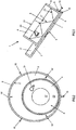
- Fig. 1 a preferred embodiment of the device 1 according to the invention is shown in connection with a drive unit 2 arranged.
- the device 1 is, as well as off Fig. 3 emerges, essentially of two nested, open to one side containers 3, 4 constructed.
- the inner container 4, also called inner shell, substrate shell or just shell, is designed in the manner of a pot or a drum, with a cone-shaped or funnel-shaped inner side or bottom mold 5.
- the material to be coated is in operation (not shown), eg a substrate as in Fig. 5 to 7 shown, recorded.
- the inner container 4 is smaller than the outer container 3 and is in Fig. 1 in the outer, larger container 3, also outer shell or - for better distinction - called plate, arranged loosely.
- both the plate 3 and the shell 4 have a flat Floor 6 and 7, so that the (outer) bottom 7 of the shell 4 completely against the (inner) bottom 6 of the plate 3.
- the bottom 7 of the shell 4 can therefore slide over the plate bottom 6.
- the side wall 8 of the plate 3 prevents the substrate shell 4 from falling or slipping out of the plate 3 as a result of the inclination.
- the plate 3 is according to Fig. 1 connected at its bottom 9 in the center with a rotary shaft 10.
- the rotary shaft 10 is mounted in a pivotable arm 11 of the drive unit 2 and protrudes through it, so that the inclination angle of the plate 3 via a pivoting of the boom 11 is adjustable.
- the rotary shaft 10 is connected for example with a friction wheel 13
- the shaft 14 is connected to a motor disposed outside the vacuum chamber (not shown), and having an O-ring-shaped friction ring 15 , Rotation of the friction wheel drive 13 therefore leads to a rotation of the inclined plate 3 about the axis of the shaft 10.
- the friction wheel 13 can be adjusted accordingly be adjusted, wherein the height of the O-ring 15 is set so that the contact between the O-ring 15 of the Reibradantriebs 13 and the rotary shaft 10 of the plate 3 is maintained.
- a screw 16 can be seen (see. Fig. 3 ), which is rotated so far radially outward that it does not rise above the inside 17 of the side wall 8. Therefore, the screw 16 in the state shown here is not a driving element and the shell 4 can slide in the plate 3 to the lowest point 18, where the outer wall 19 of the shell 4 is in contact with the inside 17 of the side wall 8 of the plate 3.
- the side wall 8 of the plate 3 extends only about up to one third of the height of the outer wall 19 of the substrate shell 4, which is perfectly sufficient at the preferred inclination angles of 14 ° to 75 °, in particular 45 ° to 50 ° to fall out of the shell 4 to prevent from the plate 3.
- the inner wall 5 'of the substrate shell 4 is below a certain Height from the outside to about half the radius funnel-shaped downwards, ie from the opening 20 to the bottom 7, tapering and rises from half the radius inwards inversely from the bottom 7 to the opening 20 towards conical up to the center 21. It thus forms an annular Recess 22 with a triangular cross-section.
- a mixing element 24 is arranged tangentially in the direction of rotation in the form of a fin.
- a target 25 is arranged in a manner known per se, from the surface 26 of which the coating material is removed by means of magnetron sputtering in a customary manner and therefore not further described here, and applied to the substrate shell 4 or to the substrate.
- the existing and thus conductive substrate shell 4 is usually connected via the plate 3 and the drive unit 2 to ground.
- the wall thickness of the shell 4 may be for example about 3 mm.
- FIG. 2 is a plan view of the device 1, wherein the different diameters of the substrate shell 4 and the plate 3 can be seen.
- the side wall 8 of the plate 3 six screws 16 are arranged at regular angular intervals, which traverse the side wall 8 in this example. Only three screws 16 are far enough rotated by the side wall 8 that they protrude from the inner side 17 radially inwardly and thus entrainment elements 16 'form. Since these three screw driving elements 16 'are completely screwed in here, they have a maximum height.
- top view of the substrate shell 4 is also the division of the inner side 5 in a radially outer, funnel-shaped portion 23 and a radially inner, conical portion 27 and the arrangement of the fin 24 in the radially outer portion 23 can be seen.
- Fig. 4A corresponds to the one described above and in the Fig. 1-3 shown position, wherein the substrate shell 4 at the lowest point 18 of the plate 3 is arranged. If the plate 3 starting from Fig. 4A rotated by about 60 ° clockwise 28, resulting in the Fig. 4B shown position. The shell 4 was taken by a screw 16 "and lifted from the lowest point 18 of the plate 3 and twisted at the same time, but the center of gravity of the shell 4 with its contents is still on the same side of the entrainment element 16" as in FIG Fig. 4A ,
- Fig. 4E the shell 4 has reached the side wall 8 of the plate 3 and is braked.
- the abrupt deceleration triggers a vibration of the shell 4 and the substrate, as in a blow to the outer wall 19 of the shell. 4
- the height of the entrainment element 16 "determines the angle at which the center of gravity of the shell 4 travels over the tip of the entrainment element 16" and thus the drop height and the shock on impact.
- the shell 4 impacting on the same location (s) could, on the one hand, cause long-term damage to the shell 4 and, on the other hand, means that some areas of the inside 5 are less affected by the detachment effect of the vibration than others.
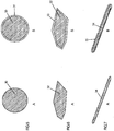
- Fig. 5A schematically shows an uncoated microsphere 30, comparable hollow glass microspheres or bulletproof glass spheres. After a coating in the device 1, the in Fig. 5B shown microsphere 30 wrapped in a layer 31 of the target material, which has a uniform thickness.
- Fig. 7A shown fiber 34 can be achieved with the device 1 without substantial bonding of the substrate or between the substrate and the substrate shell 4.
- Fig. 7B shown coated fiber 34 according to Fig. 7A has an enveloping layer 35 of the target material.
- the substrate After coating, the substrate has a uniform surface consisting of the selected target material.
Landscapes
- Chemical & Material Sciences (AREA)
- Engineering & Computer Science (AREA)
- Chemical Kinetics & Catalysis (AREA)
- Materials Engineering (AREA)
- Mechanical Engineering (AREA)
- Metallurgy (AREA)
- Organic Chemistry (AREA)
- Physics & Mathematics (AREA)
- Plasma & Fusion (AREA)
- Analytical Chemistry (AREA)
- Physical Vapour Deposition (AREA)
Description
- Die Erfindung betrifft eine Vorrichtung zum Beschichten eines Substrats aus Teilchen, wie beispielsweise Körnern, Granulaten, Pulvern, Scheibchen, Stäbchen oder Fasern, mittels Kathodenzerstäubung mit einer beweglichen, gegenüber der Horizontalebene schräggestellten Substratschale.
- Das Verfahren der Kathodenzerstäubung ist eine Methode zum zerstörungsfreien Beschichten beispielsweise von pulverförmigen oder granulatartigen Substraten.
- Die verbreitetsten Varianten zum Erzielen einer möglichst gleichmäßigen Beschichtung eines Substrats sind Wirbelbeschichtung, Hohlkathodenbeschichtung und Stabkathodenbeschichtung. Bei der Wirbelbeschichtung ist aufgrund der notwendig hohen Gasflüsse der Einsatz in Verbindung mit Kathodenzerstäubung nur begrenzt möglich. Bei der Hohlkathodenbeschichtung stellen die Zu- und Abführung des Substrates, welches durch eine vertikal angeordnete hohlzylinderförmige Kathode fällt, Schwierigkeiten dar. Bei der Stabkathodenbeschichtung, bei der sich das Substrat in einer um eine waagrechte Rotationsachse rotierenden Trommel befindet, in deren Mitte die Stabkathode angeordnet ist, sind nur geringe Beschichtungsraten möglich.
- Eine Vorrichtung der eingangs angeführten Art, welche eine gegenüber den bekannten Verfahren verbesserte Beschichtung ermöglicht, wurde bereits von G. Schmid et al., "Optimization of a container design for depositing uniform metal coatings on glass microspheres by magnetron sputtering", Surface & Coatings Technology 205 (2010) S. 1929-1936, beschrieben. Die Vorrichtung basiert auf der an sich bekannten Technik des Magnetronsputterns, wobei zusätzlich zu dem (beim Kathodenzerstäuben selbstverständlichen) elektrischen Feld ein magnetisches Feld so angeordnet ist, dass die Ladungsträger in spiralförmigen Bahnen über der Target-Oberfläche kreisen und somit eine höhere Ionisation und letztendlich eine höhere Sputterrate erzielt wird. Bei der gezeigten Vorrichtung ist eine schräggestellte Substratschale gegenüber und unterhalb des Targets angeordnet. Durch Rotieren der Substratschale wird das enthaltene Substrat durchmischt und einem Verkleben der Partikel untereinander oder mit der Behälterwand entgegengewirkt. Die in dem zitierten Artikel getestete Beschichtung von Mikroglaskugeln ist besonders anspruchsvoll, da die hohlen Glaskugeln einerseits mechanisch empfindlicher sind und generell kleine Partikel - aufgrund der geringen Dichte - stärker zum Verkleben neigen als andere, beispielsweise massive, Substrate.
- Die
US 6,355,146 zeigt ein Beschichtungsverfahren, welches Magnetronsputtern verwendet, wobei eine Substratschale entweder mittels Piezoelementen vibriert oder in der Art eines Schaufelrads gedreht wird. - Die
US 6 038 999 A1 zeigt eine Beschichtungsvorrichtung mit einer um 15° geneigten Aufnahmekammer für ein aus losen Teilen bestehendes Substrat. Ein Schütteln des Substrats wird dabei durch die Rotation der Kammer und gegebenenfalls durch zusätzliche Rührstäbe erzielt. - Der in
JP 11241157 A - Aus der
JP 2007-204786 A - In
GB 2 282 824 A - Es ist Aufgabe der Erfindung, eine Vorrichtung wie eingangs angeführt vorzuschlagen, mit der es - auf konstruktiv möglichst einfache Weise - gelingt, das Verkleben des Substrats zu vermeiden oder zumindest weiter zu reduzieren und ein Lösen des Substrats von der Schale zu ermöglichen. Die Erfindung basiert dabei auf der Idee, der Substratschale Erschütterungen in der Art von Schlägen zuzufügen. Da die Erfindung auf die Beschichtung von Substraten im Mikrometer-Bereich (Partikelgrößen von 4-1000 um) abzielt, soll ein Vibrieren der Substratschale möglichst vermieden werden, da dies häufig zur Verdichtung des Substrats und in der Folge zu verstärktem Verkleben führt. Schließlich soll die Erfindung mit den beim Magnetronsputtern notwendigen niedrigen Gasdrücken kompatibel sein.
- Die erfindungsgemäße Vorrichtung der eingangs angeführten Art löst diese Aufgabe, indem die Substratschale lose in einem um eine Rotationsachse rotierbaren, schräggestellten, eine Seitenwand aufweisenden Teller angeordnet ist, wobei eine Außenwand der Substratschale intermittierend mit der Innenseite der Seitenwand des Tellers in Kontakt steht.
- Aufgrund der losen Anordnung ist die Substratschale in einer zur Rotationsachse des Tellers senkrechten Tellerebene frei beweglich, und sie kann somit im Teller verschoben und gegenüber dem Teller gedreht werden, wobei die Bewegungsfreiheit durch die Seitenwand des Tellers beschränkt ist. Bei Rotation des Tellers wird aufgrund der Schrägstellung eine Bewegung der Substratschale im und relativ zum Teller durch die Schwerkraft erzwungen und es kommt immer dann zu Erschütterungen, wenn die Substratschale bei dieser Bewegung an die Seitenwand des Tellers stößt. Dies kann beispielsweise dadurch gefördert werden, dass Teller und Substratschale verschiedene Umrissformen aufweisen, etwa wenn die Substratschale rund/oval und der Teller vieleckig (in Draufsicht) ist. Die von der Seitenwand auf die Substratschale ausgeübte Bremskraft pflanzt sich dabei auch auf benachbart der Schalenwand angeordnete Substratpartikel fort, welche sich unter Einwirkung von parallel zur Innenseite der Substratschale wirkenden Kraftkomponenten von der Wand lösen.
- Eine abwechselnd rotierende und mit periodischen Erschütterungen durchsetzte Bewegung der Substratschale kann auf einfache Weise erzielt werden, wenn sowohl die Außenwand der Substratschale als auch die Seitenwand des Tellers zylindrisch ist, wobei die Zylinderachsen parallel sind, so dass die Substratschale im Teller zumindest abschnittsweise abrollt, und dass die Seitenwand des Tellers an der Innenseite zumindest ein Mitnahmeelement für die Substratschale aufweist. Durch die zylindrische Form und die parallelen Achsen der beiden Behälter bewegt sich die kleinere Substratschale im größeren Teller, sobald dieser gedreht wird, aufgrund der Schwerkraft immer zum tiefsten Punkt des Tellers. Damit die Schale im Teller rollt (und nicht nur gleitet) und es zu einer ständigen Umwälzung des Schaleninhalts kommt, ist es vorteilhaft, wenn zwischen der Außenwand der Substratschale und der Innenseite der Teller-Seitenwand ein gewisser Reibschluss bzw. eine gewisse Haftung besteht, was beispielsweise durch eine ausreichende Rauhigkeit der Materialien erzielt werden kann. Sobald die Substratschale auf ein Mitnahmeelement stößt, wird die Rollbewegung unterbrochen, und die Substratschale wird so lange mit dem Teller mitbewegt und im Teller angehoben, bis der Schwerpunkt der Schale samt Inhalt sich über das Mitnahmeelement verlagert. Dann rollt die Substratschale über das Mitnahmelement und rollt, fällt oder gleitet im Teller durch die Schwerkraft nach unten, bis sie an die Innenseite der Tellerwand stößt und bei dem plötzlichen Aufprall erschüttert wird. Während einer vollständigen Umdrehung des Tellers wird die Substratschale aufgrund der Relativbewegung im Teller mehr als 360° gedreht.
- In Bezug auf das Mitnahmeelement hat sich als vorteilhaft herausgestellt, wenn es durch einen radial nach innen ragenden Vorsprung gebildet ist, wobei die Höhe (Länge) des Vorsprungs kleiner ist als die Differenz zwischen dem Innenradius des Tellers und dem Außenradius der Substratschale. Die Höhe des Vorsprungs bestimmt, wie weit die Substratschale bei der Drehung des Tellers aus dem tiefsten Punkt mitgenommen wird und ein Abrollen der Substratschale über das Mitnahmeelement, d.h. über den Vorsprung, ist nur bei entsprechend geringer Höhe des Mitnahmeelements möglich. Bevorzugt beträgt die Höhe des Vorsprungs zwischen 10 und 20% des Außenradius der Substratschale, da die Schale somit einen Winkel von ca. 25° bis 35° in Rotationsrichtung im Teller mitgenommen wird. Bei der entsprechenden "Fallhöhe" ist das Ausmaß der Erschütterung ein geeigneter Kompromiss zwischen einer effektiven Ablösung von Verklebungen und einer geringen mechanischen Belastung des Substrats.
- Um die Härte bzw. das Ausmaß der Erschütterung einstellen zu können, ist es günstig, wenn das Mitnahmeelement radial verstellbar ist. Die Vorrichtung kann somit optimal an die jeweiligen Anforderungen, d.h. je nach Substrat, dessen Dichte, mechanische Stabilität und Verklumpungseigenschaften, dem Beschichtungsmaterial, der Temperatur etc., angepasst werden. Außerdem sind im Fall von mehreren Mitnahmelementen verschiedene Erschütterungsstärken einstellbar.
- Eine einfache wie effektive Möglichkeit für die Herstellung eines solchen Mitnahmeelements ist, wenn das Mitnahmeelement von einer Schraube gebildet ist, welche die Seitenwand des Tellers durchquert. Der konstruktive Aufwand zur Herstellung der Vorrichtung ist somit minimal und gleichzeitig ist eine stufenlose Einstellbarkeit der Erschütterung gegeben. Die Schrauben können bei Bedarf einfach eingesetzt, entfernt oder ersetzt werden. Aber selbstverständlich sind auch andere Formen von Mitnahmeelementen denkbar, wie z.B. Rampen, Keile oder Schaufeln, welche einen vergleichbaren Effekt erzielen können.
- Bei den oben beschriebenen zylindrischen Formen ist es günstig, wenn das Durchmesserverhältnis von Teller und Substratschale etwa 13:9 beträgt. Dieses Verhältnis, d.h. wenn der Durchmesser der Substratschale etwa 70% des Durchmessers des Tellers beträgt, bietet ausreichend Spielraum für die Dimensionierung des Mitnahmeelements, so dass für die meisten Substrate eine geeignete Erschütterung der Substratschale erzielt werden kann, während gleichzeitig der Platzbedarf der Vorrichtung nicht durch einen verhältnismäßig großen Teller über Gebühr vergrößert ist.
- In Hinblick auf das Material der Substratschale ist es vorteilhaft, wenn die Masse der Schale möglichst gering ist, da somit bei gleicher Aufprallgeschwindigkeit eine stärkere Erschütterung des Inhalts erzielt wird. Da die Substratschale außerdem elektrisch leitend und mechanisch widerstandsfähig sein soll sowie den beim Kathodenbeschichten üblichen Temperaturen standhalten muss, ist es günstig, wenn die Substratschale aus Aluminium hergestellt ist, welches darüber hinaus im Vergleich zu anderen Metallen einfach zu bearbeiten ist.
- Der Neigungswinkel des Tellers und der Substratschale ist ausschlaggebend für die Beschleunigung der Substratschale im Teller und somit auch für den Grad der Erschütterung beim Aufprall auf die Seitenwand des Tellers. Ein zu großer Neigungswinkel kann allerdings insbesondere beim Aufprall zum Austritt des Substrats aus der Schale führen und begrenzt daher die Menge des zu beschichtenden Substrats in der Substratschale. Unter diesen Erwägungen haben sich Neigungswinkel zwischen 14° und 75°, bevorzugt zwischen 45° und 50°, als besonders geeignet herausgestellt.
- Weiters ist es für eine effektive Durchmischung des Substrats günstig, wenn eine Innenwand der Substratschale in einem radial äußeren Abschnitt von der Öffnung aus trichterförmig zulaufend und in einem radial inneren Abschnitt zur Öffnung hin kegelförmig zulaufend ausgebildet ist, so dass ein Übergang zwischen den beiden so gebildeten Kegelabschnitten den tiefsten Bereich der Substratschale bildet. Der Vorteil dieses Aufbaus liegt im Zusammenspiel mit der Neigung bzw. Schrägstellung der Substratschale, da sich dabei jede innere Fläche der Schale während einer vollen Umdrehung zumindest zeitweilig zumindest annährend in der Senkrechten befindet, so dass das Substrat optimal abgleiten kann. Bei dem beschriebenen Aufbau ist bevorzugt der Übergang zwischen dem äußeren trichterförmigen Abschnitt und dem inneren kegelförmigen Abschnitt etwa bei einem halben Innenradius der Substratschale angeordnet, wobei die Neigungswinkel der beiden Abschnitte gegenüber einer senkrecht auf die Rotationsachse stehenden Ebene etwa 45° bzw. -45° betragen. Der radiale Verlauf der Schaleninnenseite beschreibt dabei ein gleichschenkeliges rechtwinkeliges Dreieck, so dass in der Neigung jeder "senkrechte" Abschnitt der Innenfläche einem etwa gleich langen "waagrechten" Abschnitt gegenüberliegt und das abgleitende Substrat optimal aufgefangen wird.
- Zur zusätzlichen Durchmischung und zum Aufbrechen etwaiger Substrat-Agglomerationen kann an der Innenwand der Substratschale zumindest ein Mischelement angeordnet sein, das bevorzugt die Form einer Finne aufweist. Insbesondere hat sich herausgestellt, dass eine tangential in Rotationsrichtung angeordnete Finne eine gute Durchmischungswirkung bei gleichzeitig geringer zusätzlicher Verklebung von Substrat an der Finne erzielt. Bei dieser Anordnung wird ein nachteiliges Schaufeln des Substrats vermieden.
- Die Erfindung wird nachfolgend anhand von besonders bevorzugten Ausführungsbeispielen, auf die sie jedoch nicht beschränkt sein soll, und unter Bezugnahme auf die Zeichnung noch weiter erläutert. In der Zeichnung zeigen dabei im Einzelnen:
-
Fig. 1 eine seitliche Schnittansicht durch eine erfindungsgemäße Vorrichtung, welche zusammen mit einem Target und einer Antriebseinheit abgebildet ist; -
Fig. 2 eine direkte Draufsicht entlang der Rotationsachse des Tellers auf die erfindungsgemäße Vorrichtung; -
Fig. 3 einen Ausschnitt ausFig. 1 , der nur die vorliegende Vorrichtung zeigt; -
Fig. 4 den Bewegungsablauf der Substratschale in dem Teller während einer Drehung des Tellers um etwa 120° anhand von fünf Stellungen in der Art von Momentaufnahmen; -
Fig. 5 schematisch einen Querschnitt eines runden Partikels bzw. eines Mikrokügelchens vor und nach einer Beschichtung; -
Fig. 6 schematisch einen Querschnitt eines kantigen Partikels vor und nach einer Beschichtung; und -
Fig. 7 schematisch einen Querschnitt eines stabförmigen Partikels vor und nach einer Beschichtung. - In
Fig. 1 ist ein bevorzugtes Ausführungsbeispiel der erfindungsgemäßen Vorrichtung 1 in Verbindung mit einer Antriebseinheit 2 angeordnet gezeigt. - Die Vorrichtung 1 ist, wie auch aus
Fig. 3 hervorgeht, im Wesentlichen aus zwei ineinander angeordneten, zu einer Seite offenen Behältern 3, 4 aufgebaut. Der innere Behälter 4, auch Innenschale, Substratschale oder einfach nur Schale genannt, ist in der Art eines Topfs oder einer Trommel ausgebildet, mit einer abschnittsweise kegel- bzw. trichterförmigen Innenseite oder Bodenform 5. In der Schale 4 ist im Betrieb das zu beschichtende Gut (nicht gezeigt), z.B. ein Substrat, wie inFig. 5 bis 7 gezeigt, aufgenommen. Der innere Behälter 4 ist kleiner als der äußere Behälter 3 und ist inFig. 1 in dem äußeren, größeren Behälter 3, auch Außenschale oder - zur besseren Unterscheidung - Teller genannt, lose angeordnet. In dem dargestellten Beispiel weisen sowohl der Teller 3 als auch die Schale 4 einen ebenen Boden 6 bzw. 7 auf, so dass der (Außen-)Boden 7 der Schale 4 vollständig an dem (Innen-)Boden 6 des Tellers 3 anliegt. Bei einer Bewegung des Tellers 3 kann der Boden 7 der Schale 4 daher über den Tellerboden 6 gleiten. Die Seitenwand 8 des Tellers 3 verhindert, dass die Substratschale 4 zufolge der Schrägstellung aus dem Teller 3 fällt oder rutscht. - Der Teller 3 ist gemäß
Fig. 1 an seiner Unterseite 9 im Mittelpunkt mit einer Drehwelle 10 verbunden. Die Drehwelle 10 ist in einem verschwenkbaren Ausleger 11 der Antriebseinheit 2 gelagert und ragt durch diesen hindurch, so dass der Neigungswinkel des Tellers 3 über eine Verschwenkung des Auslegers 11 einstellbar ist. Auf einer dem Teller 3 gegenüberliegenden Rückseite 12 des Auslegers 11 ist die Drehwelle 10 z.B. mit einem Reibradantrieb 13 verbunden, dessen Welle 14 mit einem außerhalb der Vakuumkammer angeordneten Motor (nicht gezeigt) verbunden ist, und der einen O-Ring-förmigen Reibring 15 aufweist. Eine Drehung des Reibradantriebs 13 führt daher zu einer Rotation des schräggestellten Tellers 3 um die Achse der Welle 10. Wenn der Neigungswinkel des Tellers 3 verändert wird, indem der entsprechende Ausleger 11 gelöst und im Winkel α verstellt wird, kann gegebenenfalls der Reibradantrieb 13 entsprechend angepasst werden, wobei die Höhe des O-Rings 15 derart eingestellt wird, dass der Kontakt zwischen dem O-Ring 15 des Reibradantriebs 13 und der Drehwelle 10 des Tellers 3 erhalten bleibt. - In der Seitenwand 8 des Tellers 3 ist eine Schraube 16 ersichtlich (vgl.
Fig. 3 ), welche so weit radial nach außen gedreht ist, dass sie sich nicht über die Innenseite 17 der Seitenwand 8 erhebt. Daher bildet die Schraube 16 in dem hier dargestellten Zustand kein Mitnahmeelement und die Schale 4 kann im Teller 3 bis zur tiefsten Stelle 18 gleiten, wo die Außenwand 19 der Schale 4 mit der Innenseite 17 der Seitenwand 8 des Tellers 3 in Kontakt steht. Die Seitenwand 8 des Tellers 3 reicht nur etwa bis zu einem Drittel der Höhe der Außenwand 19 der Substratschale 4, was bei den bevorzugten Neigungswinkeln von 14° bis 75°, insbesondere 45° bis 50°, vollkommen ausreichend ist, um ein Herausfallen der Schale 4 aus dem Teller 3 zu verhindern. - Die Innenwand 5' der Substratschale 4 ist unterhalb einer bestimmten Höhe von außen bis etwa zum halben Radius trichterförmig nach unten, d.h. von der Öffnung 20 zum Boden 7, zulaufend und erhebt sich ab dem halben Radius nach innen umgekehrt vom Boden 7 zur Öffnung 20 hin kegelförmig bis zum Mittelpunkt 21. Sie bildet somit eine ringförmige Vertiefung 22 mit einem dreieckförmigen Querschnitt. Im äußeren, trichterförmigen Abschnitt 23 ist ein Mischelement 24 in Form einer Finne tangential in Drehrichtung angeordnet.
- Oberhalb der Schalenöffnung 20 ist in an sich bekannter Weise ein Target 25 angeordnet, von dessen Oberfläche 26 in üblicher - und hier daher nicht weiter zu beschreibender - Weise das Beschichtungsmaterial mittels Magnetronsputtern abgetragen und auf die Substratschale 4 bzw. auf das Substrat aufgebracht wird. Die aus Aluminium bestehende und somit leitende Substratschale 4 ist gewöhnlich über den Teller 3 und die Antriebseinheit 2 mit Masse verbunden. Die Wandstärke der Schale 4 kann beispielsweise etwa 3 mm betragen.
- In
Fig. 2 ist eine Draufsicht auf die Vorrichtung 1 dargestellt, wobei die unterschiedlichen Durchmesser der Substratschale 4 und des Tellers 3 ersichtlich sind. In der Seitenwand 8 des Tellers 3 sind in diesem Beispiel sechs Schrauben 16 in regelmäßigen Winkelabständen angeordnet, welche die Seitenwand 8 durchqueren. Lediglich drei Schrauben 16 sind weit genug durch die Seitenwand 8 gedreht, dass sie von der Innenseite 17 radial nach innen ragen und somit Mitnahmeelemente 16' bilden. Da diese drei Schrauben-Mitnahmeelemente 16' hier vollständig hinein geschraubt sind, weisen sie eine maximale Höhe auf. In der inFig. 2 gezeigten Draufsicht auf die Substratschale 4 ist außerdem die Aufteilung der Innenseite 5 in einen radial äußeren, trichterförmigen Abschnitt 23 und einen radial inneren, kegelförmigen Abschnitt 27 und die Anordnung der Finne 24 im radial äußeren Abschnitt 23 erkennbar. - Der Bewegungsablauf der Schale 4 im Teller 3 bei einer Teilumdrehung des Tellers 3 ist in schematischer Schrägansicht in
Fig. 4 und deren Unterfiguren A-E gezeigt.Fig. 4A entspricht der oben beschriebenen und in denFig. 1-3 dargestellten Stellung, wobei die Substratschale 4 am tiefsten Punkt 18 des Tellers 3 angeordnet ist. Wird der Teller 3 ausgehend vonFig. 4A um etwa 60° im Uhrzeigersinn 28 gedreht, ergibt sich die inFig. 4B gezeigte Stellung. Dabei wurde die Schale 4 von einer Schraube 16" mitgenommen und aus dem tiefsten Punkt 18 des Tellers 3 angehoben und gleichzeitig verdreht. Der Schwerpunkt der Schale 4 samt Inhalt befindet sich hier allerdings noch auf derselben Seite des Mitnahmeelements 16" wie inFig. 4A . - Das ändert sich bei einer weiteren Drehung des Tellers 3 um etwa 30°, wonach die in
Fig. 4C gezeigte Stellung erreicht ist. Die Schale 4 wurde hier ebenfalls entsprechend weiter gedreht und beginnt nun, über die Spitze der Schraube 16" abzurollen. - In der Situation gemäß
Fig. 4D ist die Schale 4 beinahe vollständig über die Schraube 16" abgerollt und sie erfährt aufgrund der Schwerkraft eine Beschleunigung (Pfeil 29) nach unten bzw. entlang des Tellerbodens 6, mit dem sie weiterhin in Kontakt steht. - In
Fig. 4E hat die Schale 4 die Seitenwand 8 des Tellers 3 erreicht und wird abgebremst. Das abrupte Abbremsen löst eine Erschütterung der Schale 4 und des Substrats aus, wie bei einem Schlag auf die Außenwand 19 der Schale 4. - Aus dem beschriebenen Ablauf wird klar, dass die Höhe des Mitnahmeelements 16" den Winkel bestimmt, bei dem der Schwerpunkt der Schale 4 über die Spitze des Mitnahmeelements 16" wandert und somit die Fallhöhe und die Erschütterung beim Aufprall.
- Unter der Annahme einer konstanten Winkelgeschwindigkeit des Tellers 3 wiederholt sich beim gezeigten Beispiel der beschriebene Vorgang bei einer vollständigen Umdrehung des Tellers 3 für jede Schraube 16', 16", d.h. insgesamt drei Mal, da die Höhe aller drei Schrauben 16', 16" gleich ist. Falls Erschütterungen verschiedener Intensität erwünscht sind, können die Schrauben 16, 16', 16" auf verschiedene Höhen eingestellt werden. Es ist günstig, darauf zu achten, dass die Anordnung der Schrauben 16, 16', 16" und das Durchmesserverhältnis von Schale 4 und Teller 3 so gewählt sind, dass die Erschütterung in möglichst vielen verschiedenen Stellungen der Schale 4 eintritt. Eine periodisch immer auf dieselbe(n) Stelle(n) aufschlagende Schale 4 könnte einerseits langfristig zu Beschädigungen der Schale 4 führen und bedeutet andererseits, dass manche Bereiche der Innenseite 5 von der Ablösewirkung der Erschütterung weniger betroffen sind als andere.
- Zur Illustration der erzielten gleichmäßigen Beschichtung sind in
Fig. 5-7 Beispiele für unbeschichtetes und beschichtetes Substrat verschiedener Struktur - jeweils nebeneinander - dargestellt. -
Fig. 5A zeigt schematisch eine unbeschichtete Mikrokugel 30, vergleichbar hohlen Mikroglaskugeln oder Panzerglaskugeln. Nach einer Beschichtung in der Vorrichtung 1 ist die inFig. 5B gezeigte Mikrokugel 30 in eine Schicht 31 des Targetmaterials eingehüllt, welche eine gleichmäßige Stärke aufweist. - Ein vergleichbares Ergebnis kann auch für ein kantiges Partikel 32 oder Granulate, wie Diamanten oder Wolframcarbidpartikeln, gemäß
Fig. 6A erzielt werden. Die entsprechende, inFig 6B gezeigte Beschichtung 33 weist zwar geringfügige Unregelmäßigkeiten auf, erzielt aber ebenso eine vollständige Umhüllung des Substrats 32. - Auch eine gleichmäßige Beschichtung von Mikrofasern, z.B. Karbonfasern, oder faser- oder stäbchenartigen Substraten, wie die in
Fig. 7A gezeigte Faser 34, kann mit der Vorrichtung 1 ohne wesentliches Verkleben des Substrats oder zwischen Substrat und Substratschale 4 erzielt werden. Die inFig. 7B gezeigte beschichtete Faser 34 gemäßFig. 7A weist eine einhüllende Schicht 35 des Targetmaterials auf. - In allen Fällen weist das Substrat nach der Beschichtung eine einheitliche Oberfläche bestehend aus dem gewählten Targetmaterial auf.
- Neben den dargestellten Beispielen einer runden Schale 4 und eines runden Tellers 3 sind selbstverständlich auch andere Formen denkbar. So wurde beispielsweise mit einer quadratischen Tellerform experimentiert, wobei die ebenen Seitenwände vergleichbar den Mitnahmeelementen funktionieren. Die Schale bewegt sich dabei immer in die tiefste Ecke des Tellers. Wird der Teller gedreht, wobei die Schale mitgeführt wird, und eine andere Ecke erreicht einen tieferen Punkt als jene, in der sich die Schale befindet, gleitet oder rollt die Schale zu dieser neuen Ecke entlang der verbindenden Seitenwand und stößt dort an die dazu senkrechte Seitenwand, was die erfindungsgemäße Erschütterung bewirkt. Allerdings sind runde Behälter 3, 4 im Allgemeinen einfacher und wirtschaftlicher herzustellen, weshalb sie hier als bevorzugte Ausführungen beschrieben wurden.
Claims (11)
- Vorrichtung (1) zum Beschichten eines Substrats aus Teilchen mittels Kathodenzerstäubung mit einer beweglichen, gegenüber der Horizontalebene schräggestellten Substratschale (4), dadurch gekennzeichnet, dass die Substratschale (4) lose in einem um eine Rotationsachse (10) rotierbaren, schräggestellten, eine Seitenwand (8) aufweisenden Teller (3) angeordnet ist, wobei eine Außenwand (19) der Substratschale (4) intermittierend mit der Innenseite (17) der Seitenwand (8) des Tellers (3) in Kontakt steht.
- Vorrichtung (1) nach Anspruch 1, dadurch gekennzeichnet, dass sowohl die Außenwand (19) der Substratschale (4) als auch die Seitenwand (8) des Tellers (3) zylindrisch ist, wobei die Zylinderachsen parallel sind, so dass die Substratschale (4) im Teller (3) zumindest abschnittsweise abrollt, und dass die Seitenwand (8) des Tellers (3) an der Innenseite (17) zumindest ein Mitnahmeelement (16') für die Substratschale (4) aufweist.
- Vorrichtung (1) nach Anspruch 2, dadurch gekennzeichnet, dass das Mitnahmeelement (16') durch einen radial nach innen ragenden Vorsprung gebildet ist, wobei die Höhe des Vorsprungs kleiner ist als die Differenz zwischen dem Innenradius des Tellers (3) und dem Außenradius der Substratschale (4) und bevorzugt zwischen 10 und 20% des Außenradius der Substratschale (4) beträgt.
- Vorrichtung (1) nach Anspruch 2 oder 3, dadurch gekennzeichnet, dass das Mitnahmeelement (16') radial verstellbar ist.
- Vorrichtung (1) nach einem der Ansprüche 2 bis 4, dadurch gekennzeichnet, dass das Mitnahmeelement (16') von einer Schraube gebildet ist, welche die Seitenwand (8) des Tellers (3) durchquert.
- Vorrichtung (1) nach einem der Ansprüche 2 bis 5, dadurch gekennzeichnet, dass das Durchmesserverhältnis von Teller (3) und Substratschale (4) etwa 13:9 beträgt.
- Vorrichtung (1) nach einem der Ansprüche 1 bis 6, dadurch gekennzeichnet, dass die Substratschale (4) aus Aluminium hergestellt ist.
- Vorrichtung (1) nach einem der Ansprüche 1 bis 7, dadurch gekennzeichnet, dass der Neigungswinkel des Tellers (3) und der Substratschale (4) zwischen 14° und 75°, bevorzugt zwischen 45° und 50°, beträgt.
- Vorrichtung (1) nach einem der Ansprüche 1 bis 8, dadurch gekennzeichnet, dass eine Innenwand (5') der Substratschale (4) in einem radial äußeren Abschnitt (23) von der Öffnung (20) aus trichterförmig zulaufend und in einem radial inneren Abschnitt (27) zur Öffnung (20) hin kegelförmig zulaufend ausgebildet ist, so dass ein Übergang zwischen den beiden so gebildeten Kegelabschnitten (23, 27) den tiefsten Bereich der Substratschale (4) bildet.
- Vorrichtung (1) nach Anspruch 9, dadurch gekennzeichnet, dass der Übergang zwischen dem äußeren trichterförmigen Abschnitt (23) und dem inneren kegelförmigen Abschnitt (27) etwa bei einem halben Innenradius der Substratschale (4) angeordnet ist und die Neigungswinkel der beiden Abschnitte (23, 27) gegenüber einer senkrecht auf die Rotationsachse (10) stehenden Ebene etwa 45° bzw. -45° betragen.
- Vorrichtung nach einem der Ansprüche 1 bis 10, dadurch gekennzeichnet, dass an der Innenwand (5') der Substratschale (4) zumindest ein Mischelement (24) angeordnet ist, das bevorzugt die Form einer Finne aufweist.
Applications Claiming Priority (2)
| Application Number | Priority Date | Filing Date | Title |
|---|---|---|---|
| ATA50406/2012A AT513037B1 (de) | 2012-09-21 | 2012-09-21 | Vorrichtung zum Beschichten eines Substrats |
| PCT/AT2013/050181 WO2014043728A1 (de) | 2012-09-21 | 2013-09-13 | Vorrichtung zum beschichten eines substrats aus teilchen |
Publications (2)
| Publication Number | Publication Date |
|---|---|
| EP2898110A1 EP2898110A1 (de) | 2015-07-29 |
| EP2898110B1 true EP2898110B1 (de) | 2016-05-25 |
Family
ID=49585228
Family Applications (1)
| Application Number | Title | Priority Date | Filing Date |
|---|---|---|---|
| EP13791899.1A Active EP2898110B1 (de) | 2012-09-21 | 2013-09-13 | Vorrichtung zum beschichten eines substrats aus teilchen |
Country Status (4)
| Country | Link |
|---|---|
| US (1) | US20150211110A1 (de) |
| EP (1) | EP2898110B1 (de) |
| AT (1) | AT513037B1 (de) |
| WO (1) | WO2014043728A1 (de) |
Family Cites Families (9)
| Publication number | Priority date | Publication date | Assignee | Title |
|---|---|---|---|---|
| GB2282824A (en) * | 1993-10-14 | 1995-04-19 | Secr Defence | Reinforcement particles pre-coated with metal matrix; particle-reinforced metal matrix composites |
| FR2727132B1 (fr) * | 1994-11-18 | 1996-12-20 | Surface Engineering | Appareil de depot sous vide relatif d'un materiau sur des pieces en vrac |
| US6355146B1 (en) | 1996-04-03 | 2002-03-12 | The Regents Of The University Of California | Sputtering process and apparatus for coating powders |
| DE19730993B4 (de) * | 1997-07-18 | 2008-04-03 | Ald Vacuum Technologies Ag | Vakuumbeschichtungsvorrichtung zum allseitigen Beschichten von Substraten durch Rotation der Substrate im Partikelstrom |
| JP3916019B2 (ja) * | 1998-02-26 | 2007-05-16 | コーア株式会社 | 着膜装置およびその方法 |
| JP4660241B2 (ja) * | 2005-03-25 | 2011-03-30 | 株式会社昭和真空 | スパッタ装置 |
| JP2007204786A (ja) * | 2006-01-31 | 2007-08-16 | Bridgestone Corp | 粒子コーティング方法及び粒子コーティング装置 |
| JP5039487B2 (ja) * | 2007-09-26 | 2012-10-03 | 株式会社アルバック | 金属蒸着装置および同装置における粉体状担体の撹拌方法 |
| CN103052734A (zh) * | 2010-08-04 | 2013-04-17 | 株式会社岛津制作所 | 表面处理装置和表面处理方法 |
-
2012
- 2012-09-21 AT ATA50406/2012A patent/AT513037B1/de active
-
2013
- 2013-09-13 EP EP13791899.1A patent/EP2898110B1/de active Active
- 2013-09-13 WO PCT/AT2013/050181 patent/WO2014043728A1/de not_active Ceased
- 2013-09-13 US US14/429,130 patent/US20150211110A1/en not_active Abandoned
Also Published As
| Publication number | Publication date |
|---|---|
| AT513037A4 (de) | 2014-01-15 |
| EP2898110A1 (de) | 2015-07-29 |
| AT513037B1 (de) | 2014-01-15 |
| US20150211110A1 (en) | 2015-07-30 |
| WO2014043728A1 (de) | 2014-03-27 |
Similar Documents
| Publication | Publication Date | Title |
|---|---|---|
| EP2978534B1 (de) | Granulatkonditionierer | |
| DE3883669T2 (de) | Vorrichtung, insbesondere zum gleichmässigen Verteilen fester Teilchen oder/und Flüssigkeiten, und Apparat mit einer solchen Vorrichtung. | |
| AT502777B1 (de) | Verfahren zur herstellung von partikeln aus einem keramischen werkstoff | |
| EP0343466B1 (de) | Vorrichtung und Verfahren zur gleichmässigen Verteilung von Material auf einer Kreisfläche | |
| EP2458345B1 (de) | Dosiersystem | |
| DE3341184A1 (de) | Verfahren zum erzeugen von ultrafeinen festen metallteilchen | |
| DE1471964B2 (de) | Mischvorrichtung, insbesondere zum Mischen von Gemengen zur Glasherstellung | |
| DE69910934T2 (de) | Verfahren zur Herstellung von kugelförmigen Formkörpern | |
| DE915408C (de) | Verfahren zum Betrieb einer Muehle | |
| AT513037B1 (de) | Vorrichtung zum Beschichten eines Substrats | |
| DE2253353A1 (de) | Sortiereinrichtung | |
| DE3626044C2 (de) | ||
| DE2318560C2 (de) | Silo zum Speichern und Entnehmen von schüttfähigem, jedoch schwerfließendem Gut | |
| DE2006503C3 (de) | Verfahren und Vorrichtungen zur kontinuierlichen Herstellung von Pulveragglomeraten | |
| DE4319702A1 (de) | Prallbrecher | |
| DE2341504A1 (de) | Wirbelschicht-spruehgranulieren im schnell-verfahren | |
| DE10302475B4 (de) | Vorrichtung zur Herstellung von Formteilen | |
| DE2615506A1 (de) | Vorrichtung zum benetzen pulverfoermiger bis koerniger schuettgueter mit fluessigkeit | |
| WO1995029114A1 (de) | Vorrichtung zum dosierten austragen von schüttfähigem feststoff | |
| DE2122395A1 (de) | ||
| AT381970B (de) | Einrichtung zum sortieren der festen teilchen einer faserstoffsuspension in fraktionen | |
| DE2554853C2 (de) | Verfahren zum Betrieb eines Siebtrommelbrechers | |
| DE456596C (de) | Kreiselmuehle | |
| DE19915122A1 (de) | Steigrohrsichter für die Wirbelschichtgranulation | |
| DE1792014C3 (de) | Drehtrommel zum Agglomerieren von feinteiligem Material |
Legal Events
| Date | Code | Title | Description |
|---|---|---|---|
| PUAI | Public reference made under article 153(3) epc to a published international application that has entered the european phase |
Free format text: ORIGINAL CODE: 0009012 |
|
| 17P | Request for examination filed |
Effective date: 20150219 |
|
| AK | Designated contracting states |
Kind code of ref document: A1 Designated state(s): AL AT BE BG CH CY CZ DE DK EE ES FI FR GB GR HR HU IE IS IT LI LT LU LV MC MK MT NL NO PL PT RO RS SE SI SK SM TR |
|
| AX | Request for extension of the european patent |
Extension state: BA ME |
|
| GRAP | Despatch of communication of intention to grant a patent |
Free format text: ORIGINAL CODE: EPIDOSNIGR1 |
|
| RIC1 | Information provided on ipc code assigned before grant |
Ipc: C23C 14/34 20060101ALI20151113BHEP Ipc: C23C 14/50 20060101ALI20151113BHEP Ipc: C23C 14/22 20060101AFI20151113BHEP Ipc: H01J 37/34 20060101ALI20151113BHEP |
|
| DAX | Request for extension of the european patent (deleted) | ||
| INTG | Intention to grant announced |
Effective date: 20151204 |
|
| GRAS | Grant fee paid |
Free format text: ORIGINAL CODE: EPIDOSNIGR3 |
|
| GRAA | (expected) grant |
Free format text: ORIGINAL CODE: 0009210 |
|
| AK | Designated contracting states |
Kind code of ref document: B1 Designated state(s): AL AT BE BG CH CY CZ DE DK EE ES FI FR GB GR HR HU IE IS IT LI LT LU LV MC MK MT NL NO PL PT RO RS SE SI SK SM TR |
|
| REG | Reference to a national code |
Ref country code: GB Ref legal event code: FG4D Free format text: NOT ENGLISH |
|
| REG | Reference to a national code |
Ref country code: CH Ref legal event code: EP |
|
| REG | Reference to a national code |
Ref country code: IE Ref legal event code: FG4D Free format text: LANGUAGE OF EP DOCUMENT: GERMAN Ref country code: AT Ref legal event code: REF Ref document number: 802389 Country of ref document: AT Kind code of ref document: T Effective date: 20160615 |
|
| REG | Reference to a national code |
Ref country code: DE Ref legal event code: R096 Ref document number: 502013003226 Country of ref document: DE |
|
| REG | Reference to a national code |
Ref country code: FR Ref legal event code: PLFP Year of fee payment: 4 |
|
| REG | Reference to a national code |
Ref country code: LT Ref legal event code: MG4D |
|
| REG | Reference to a national code |
Ref country code: NL Ref legal event code: MP Effective date: 20160525 |
|
| PG25 | Lapsed in a contracting state [announced via postgrant information from national office to epo] |
Ref country code: LT Free format text: LAPSE BECAUSE OF FAILURE TO SUBMIT A TRANSLATION OF THE DESCRIPTION OR TO PAY THE FEE WITHIN THE PRESCRIBED TIME-LIMIT Effective date: 20160525 Ref country code: NO Free format text: LAPSE BECAUSE OF FAILURE TO SUBMIT A TRANSLATION OF THE DESCRIPTION OR TO PAY THE FEE WITHIN THE PRESCRIBED TIME-LIMIT Effective date: 20160825 Ref country code: FI Free format text: LAPSE BECAUSE OF FAILURE TO SUBMIT A TRANSLATION OF THE DESCRIPTION OR TO PAY THE FEE WITHIN THE PRESCRIBED TIME-LIMIT Effective date: 20160525 Ref country code: NL Free format text: LAPSE BECAUSE OF FAILURE TO SUBMIT A TRANSLATION OF THE DESCRIPTION OR TO PAY THE FEE WITHIN THE PRESCRIBED TIME-LIMIT Effective date: 20160525 |
|
| PG25 | Lapsed in a contracting state [announced via postgrant information from national office to epo] |
Ref country code: RS Free format text: LAPSE BECAUSE OF FAILURE TO SUBMIT A TRANSLATION OF THE DESCRIPTION OR TO PAY THE FEE WITHIN THE PRESCRIBED TIME-LIMIT Effective date: 20160525 Ref country code: ES Free format text: LAPSE BECAUSE OF FAILURE TO SUBMIT A TRANSLATION OF THE DESCRIPTION OR TO PAY THE FEE WITHIN THE PRESCRIBED TIME-LIMIT Effective date: 20160525 Ref country code: SE Free format text: LAPSE BECAUSE OF FAILURE TO SUBMIT A TRANSLATION OF THE DESCRIPTION OR TO PAY THE FEE WITHIN THE PRESCRIBED TIME-LIMIT Effective date: 20160525 Ref country code: LV Free format text: LAPSE BECAUSE OF FAILURE TO SUBMIT A TRANSLATION OF THE DESCRIPTION OR TO PAY THE FEE WITHIN THE PRESCRIBED TIME-LIMIT Effective date: 20160525 Ref country code: PT Free format text: LAPSE BECAUSE OF FAILURE TO SUBMIT A TRANSLATION OF THE DESCRIPTION OR TO PAY THE FEE WITHIN THE PRESCRIBED TIME-LIMIT Effective date: 20160926 Ref country code: GR Free format text: LAPSE BECAUSE OF FAILURE TO SUBMIT A TRANSLATION OF THE DESCRIPTION OR TO PAY THE FEE WITHIN THE PRESCRIBED TIME-LIMIT Effective date: 20160826 |
|
| PG25 | Lapsed in a contracting state [announced via postgrant information from national office to epo] |
Ref country code: IT Free format text: LAPSE BECAUSE OF FAILURE TO SUBMIT A TRANSLATION OF THE DESCRIPTION OR TO PAY THE FEE WITHIN THE PRESCRIBED TIME-LIMIT Effective date: 20160525 |
|
| PG25 | Lapsed in a contracting state [announced via postgrant information from national office to epo] |
Ref country code: DK Free format text: LAPSE BECAUSE OF FAILURE TO SUBMIT A TRANSLATION OF THE DESCRIPTION OR TO PAY THE FEE WITHIN THE PRESCRIBED TIME-LIMIT Effective date: 20160525 Ref country code: SK Free format text: LAPSE BECAUSE OF FAILURE TO SUBMIT A TRANSLATION OF THE DESCRIPTION OR TO PAY THE FEE WITHIN THE PRESCRIBED TIME-LIMIT Effective date: 20160525 Ref country code: EE Free format text: LAPSE BECAUSE OF FAILURE TO SUBMIT A TRANSLATION OF THE DESCRIPTION OR TO PAY THE FEE WITHIN THE PRESCRIBED TIME-LIMIT Effective date: 20160525 Ref country code: CZ Free format text: LAPSE BECAUSE OF FAILURE TO SUBMIT A TRANSLATION OF THE DESCRIPTION OR TO PAY THE FEE WITHIN THE PRESCRIBED TIME-LIMIT Effective date: 20160525 Ref country code: RO Free format text: LAPSE BECAUSE OF FAILURE TO SUBMIT A TRANSLATION OF THE DESCRIPTION OR TO PAY THE FEE WITHIN THE PRESCRIBED TIME-LIMIT Effective date: 20160525 |
|
| PG25 | Lapsed in a contracting state [announced via postgrant information from national office to epo] |
Ref country code: SM Free format text: LAPSE BECAUSE OF FAILURE TO SUBMIT A TRANSLATION OF THE DESCRIPTION OR TO PAY THE FEE WITHIN THE PRESCRIBED TIME-LIMIT Effective date: 20160525 Ref country code: BE Free format text: LAPSE BECAUSE OF NON-PAYMENT OF DUE FEES Effective date: 20160930 Ref country code: PL Free format text: LAPSE BECAUSE OF FAILURE TO SUBMIT A TRANSLATION OF THE DESCRIPTION OR TO PAY THE FEE WITHIN THE PRESCRIBED TIME-LIMIT Effective date: 20160525 |
|
| REG | Reference to a national code |
Ref country code: DE Ref legal event code: R097 Ref document number: 502013003226 Country of ref document: DE |
|
| PLBE | No opposition filed within time limit |
Free format text: ORIGINAL CODE: 0009261 |
|
| STAA | Information on the status of an ep patent application or granted ep patent |
Free format text: STATUS: NO OPPOSITION FILED WITHIN TIME LIMIT |
|
| PG25 | Lapsed in a contracting state [announced via postgrant information from national office to epo] |
Ref country code: MC Free format text: LAPSE BECAUSE OF FAILURE TO SUBMIT A TRANSLATION OF THE DESCRIPTION OR TO PAY THE FEE WITHIN THE PRESCRIBED TIME-LIMIT Effective date: 20160525 |
|
| REG | Reference to a national code |
Ref country code: CH Ref legal event code: PL |
|
| 26N | No opposition filed |
Effective date: 20170228 |
|
| PG25 | Lapsed in a contracting state [announced via postgrant information from national office to epo] |
Ref country code: SI Free format text: LAPSE BECAUSE OF FAILURE TO SUBMIT A TRANSLATION OF THE DESCRIPTION OR TO PAY THE FEE WITHIN THE PRESCRIBED TIME-LIMIT Effective date: 20160525 |
|
| REG | Reference to a national code |
Ref country code: IE Ref legal event code: MM4A |
|
| PG25 | Lapsed in a contracting state [announced via postgrant information from national office to epo] |
Ref country code: CH Free format text: LAPSE BECAUSE OF NON-PAYMENT OF DUE FEES Effective date: 20160930 Ref country code: IE Free format text: LAPSE BECAUSE OF NON-PAYMENT OF DUE FEES Effective date: 20160913 Ref country code: LI Free format text: LAPSE BECAUSE OF NON-PAYMENT OF DUE FEES Effective date: 20160930 |
|
| PG25 | Lapsed in a contracting state [announced via postgrant information from national office to epo] |
Ref country code: LU Free format text: LAPSE BECAUSE OF NON-PAYMENT OF DUE FEES Effective date: 20160913 |
|
| REG | Reference to a national code |
Ref country code: FR Ref legal event code: PLFP Year of fee payment: 5 |
|
| REG | Reference to a national code |
Ref country code: BE Ref legal event code: MM Effective date: 20160930 |
|
| PG25 | Lapsed in a contracting state [announced via postgrant information from national office to epo] |
Ref country code: HU Free format text: LAPSE BECAUSE OF FAILURE TO SUBMIT A TRANSLATION OF THE DESCRIPTION OR TO PAY THE FEE WITHIN THE PRESCRIBED TIME-LIMIT; INVALID AB INITIO Effective date: 20130913 |
|
| PG25 | Lapsed in a contracting state [announced via postgrant information from national office to epo] |
Ref country code: MK Free format text: LAPSE BECAUSE OF FAILURE TO SUBMIT A TRANSLATION OF THE DESCRIPTION OR TO PAY THE FEE WITHIN THE PRESCRIBED TIME-LIMIT Effective date: 20160525 Ref country code: CY Free format text: LAPSE BECAUSE OF FAILURE TO SUBMIT A TRANSLATION OF THE DESCRIPTION OR TO PAY THE FEE WITHIN THE PRESCRIBED TIME-LIMIT Effective date: 20160525 Ref country code: HR Free format text: LAPSE BECAUSE OF FAILURE TO SUBMIT A TRANSLATION OF THE DESCRIPTION OR TO PAY THE FEE WITHIN THE PRESCRIBED TIME-LIMIT Effective date: 20160525 Ref country code: MT Free format text: LAPSE BECAUSE OF FAILURE TO SUBMIT A TRANSLATION OF THE DESCRIPTION OR TO PAY THE FEE WITHIN THE PRESCRIBED TIME-LIMIT Effective date: 20160525 Ref country code: IS Free format text: LAPSE BECAUSE OF FAILURE TO SUBMIT A TRANSLATION OF THE DESCRIPTION OR TO PAY THE FEE WITHIN THE PRESCRIBED TIME-LIMIT Effective date: 20160525 |
|
| PG25 | Lapsed in a contracting state [announced via postgrant information from national office to epo] |
Ref country code: BG Free format text: LAPSE BECAUSE OF FAILURE TO SUBMIT A TRANSLATION OF THE DESCRIPTION OR TO PAY THE FEE WITHIN THE PRESCRIBED TIME-LIMIT Effective date: 20160525 |
|
| REG | Reference to a national code |
Ref country code: FR Ref legal event code: PLFP Year of fee payment: 6 |
|
| PG25 | Lapsed in a contracting state [announced via postgrant information from national office to epo] |
Ref country code: AL Free format text: LAPSE BECAUSE OF FAILURE TO SUBMIT A TRANSLATION OF THE DESCRIPTION OR TO PAY THE FEE WITHIN THE PRESCRIBED TIME-LIMIT Effective date: 20160525 Ref country code: TR Free format text: LAPSE BECAUSE OF FAILURE TO SUBMIT A TRANSLATION OF THE DESCRIPTION OR TO PAY THE FEE WITHIN THE PRESCRIBED TIME-LIMIT Effective date: 20160525 |
|
| REG | Reference to a national code |
Ref country code: AT Ref legal event code: MM01 Ref document number: 802389 Country of ref document: AT Kind code of ref document: T Effective date: 20180913 |
|
| PG25 | Lapsed in a contracting state [announced via postgrant information from national office to epo] |
Ref country code: AT Free format text: LAPSE BECAUSE OF NON-PAYMENT OF DUE FEES Effective date: 20180913 |
|
| P01 | Opt-out of the competence of the unified patent court (upc) registered |
Effective date: 20230630 |
|
| PGFP | Annual fee paid to national office [announced via postgrant information from national office to epo] |
Ref country code: DE Payment date: 20250919 Year of fee payment: 13 |
|
| PGFP | Annual fee paid to national office [announced via postgrant information from national office to epo] |
Ref country code: GB Payment date: 20250923 Year of fee payment: 13 |
|
| PGFP | Annual fee paid to national office [announced via postgrant information from national office to epo] |
Ref country code: FR Payment date: 20250924 Year of fee payment: 13 |