EP2896870B1 - Verfahren und Vorrichtung zum automatischen seriellen Befüllen von Druckflaschen mit Gas - Google Patents
Verfahren und Vorrichtung zum automatischen seriellen Befüllen von Druckflaschen mit Gas Download PDFInfo
- Publication number
- EP2896870B1 EP2896870B1 EP14151735.9A EP14151735A EP2896870B1 EP 2896870 B1 EP2896870 B1 EP 2896870B1 EP 14151735 A EP14151735 A EP 14151735A EP 2896870 B1 EP2896870 B1 EP 2896870B1
- Authority
- EP
- European Patent Office
- Prior art keywords
- filling
- pressure
- conveyor belt
- pressure cylinders
- longitudinal axis
- Prior art date
- Legal status (The legal status is an assumption and is not a legal conclusion. Google has not performed a legal analysis and makes no representation as to the accuracy of the status listed.)
- Active
Links
Images



Classifications
-
- F—MECHANICAL ENGINEERING; LIGHTING; HEATING; WEAPONS; BLASTING
- F17—STORING OR DISTRIBUTING GASES OR LIQUIDS
- F17C—VESSELS FOR CONTAINING OR STORING COMPRESSED, LIQUEFIED OR SOLIDIFIED GASES; FIXED-CAPACITY GAS-HOLDERS; FILLING VESSELS WITH, OR DISCHARGING FROM VESSELS, COMPRESSED, LIQUEFIED, OR SOLIDIFIED GASES
- F17C5/00—Methods or apparatus for filling containers with liquefied, solidified, or compressed gases under pressures
- F17C5/002—Automated filling apparatus
- F17C5/005—Automated filling apparatus for gas bottles, such as on a continuous belt or on a merry-go-round
-
- F—MECHANICAL ENGINEERING; LIGHTING; HEATING; WEAPONS; BLASTING
- F17—STORING OR DISTRIBUTING GASES OR LIQUIDS
- F17C—VESSELS FOR CONTAINING OR STORING COMPRESSED, LIQUEFIED OR SOLIDIFIED GASES; FIXED-CAPACITY GAS-HOLDERS; FILLING VESSELS WITH, OR DISCHARGING FROM VESSELS, COMPRESSED, LIQUEFIED, OR SOLIDIFIED GASES
- F17C2201/00—Vessel construction, in particular geometry, arrangement or size
- F17C2201/05—Size
- F17C2201/056—Small (<1 m3)
-
- F—MECHANICAL ENGINEERING; LIGHTING; HEATING; WEAPONS; BLASTING
- F17—STORING OR DISTRIBUTING GASES OR LIQUIDS
- F17C—VESSELS FOR CONTAINING OR STORING COMPRESSED, LIQUEFIED OR SOLIDIFIED GASES; FIXED-CAPACITY GAS-HOLDERS; FILLING VESSELS WITH, OR DISCHARGING FROM VESSELS, COMPRESSED, LIQUEFIED, OR SOLIDIFIED GASES
- F17C2201/00—Vessel construction, in particular geometry, arrangement or size
- F17C2201/05—Size
- F17C2201/058—Size portable (<30 l)
-
- F—MECHANICAL ENGINEERING; LIGHTING; HEATING; WEAPONS; BLASTING
- F17—STORING OR DISTRIBUTING GASES OR LIQUIDS
- F17C—VESSELS FOR CONTAINING OR STORING COMPRESSED, LIQUEFIED OR SOLIDIFIED GASES; FIXED-CAPACITY GAS-HOLDERS; FILLING VESSELS WITH, OR DISCHARGING FROM VESSELS, COMPRESSED, LIQUEFIED, OR SOLIDIFIED GASES
- F17C2205/00—Vessel construction, in particular mounting arrangements, attachments or identifications means
- F17C2205/05—Vessel or content identifications, e.g. labels
- F17C2205/054—Vessel or content identifications, e.g. labels by bar codes
-
- F—MECHANICAL ENGINEERING; LIGHTING; HEATING; WEAPONS; BLASTING
- F17—STORING OR DISTRIBUTING GASES OR LIQUIDS
- F17C—VESSELS FOR CONTAINING OR STORING COMPRESSED, LIQUEFIED OR SOLIDIFIED GASES; FIXED-CAPACITY GAS-HOLDERS; FILLING VESSELS WITH, OR DISCHARGING FROM VESSELS, COMPRESSED, LIQUEFIED, OR SOLIDIFIED GASES
- F17C2221/00—Handled fluid, in particular type of fluid
- F17C2221/01—Pure fluids
- F17C2221/011—Oxygen
-
- F—MECHANICAL ENGINEERING; LIGHTING; HEATING; WEAPONS; BLASTING
- F17—STORING OR DISTRIBUTING GASES OR LIQUIDS
- F17C—VESSELS FOR CONTAINING OR STORING COMPRESSED, LIQUEFIED OR SOLIDIFIED GASES; FIXED-CAPACITY GAS-HOLDERS; FILLING VESSELS WITH, OR DISCHARGING FROM VESSELS, COMPRESSED, LIQUEFIED, OR SOLIDIFIED GASES
- F17C2221/00—Handled fluid, in particular type of fluid
- F17C2221/01—Pure fluids
- F17C2221/012—Hydrogen
-
- F—MECHANICAL ENGINEERING; LIGHTING; HEATING; WEAPONS; BLASTING
- F17—STORING OR DISTRIBUTING GASES OR LIQUIDS
- F17C—VESSELS FOR CONTAINING OR STORING COMPRESSED, LIQUEFIED OR SOLIDIFIED GASES; FIXED-CAPACITY GAS-HOLDERS; FILLING VESSELS WITH, OR DISCHARGING FROM VESSELS, COMPRESSED, LIQUEFIED, OR SOLIDIFIED GASES
- F17C2221/00—Handled fluid, in particular type of fluid
- F17C2221/01—Pure fluids
- F17C2221/014—Nitrogen
-
- F—MECHANICAL ENGINEERING; LIGHTING; HEATING; WEAPONS; BLASTING
- F17—STORING OR DISTRIBUTING GASES OR LIQUIDS
- F17C—VESSELS FOR CONTAINING OR STORING COMPRESSED, LIQUEFIED OR SOLIDIFIED GASES; FIXED-CAPACITY GAS-HOLDERS; FILLING VESSELS WITH, OR DISCHARGING FROM VESSELS, COMPRESSED, LIQUEFIED, OR SOLIDIFIED GASES
- F17C2221/00—Handled fluid, in particular type of fluid
- F17C2221/01—Pure fluids
- F17C2221/016—Noble gases (Ar, Kr, Xe)
- F17C2221/017—Helium
-
- F—MECHANICAL ENGINEERING; LIGHTING; HEATING; WEAPONS; BLASTING
- F17—STORING OR DISTRIBUTING GASES OR LIQUIDS
- F17C—VESSELS FOR CONTAINING OR STORING COMPRESSED, LIQUEFIED OR SOLIDIFIED GASES; FIXED-CAPACITY GAS-HOLDERS; FILLING VESSELS WITH, OR DISCHARGING FROM VESSELS, COMPRESSED, LIQUEFIED, OR SOLIDIFIED GASES
- F17C2221/00—Handled fluid, in particular type of fluid
- F17C2221/03—Mixtures
-
- F—MECHANICAL ENGINEERING; LIGHTING; HEATING; WEAPONS; BLASTING
- F17—STORING OR DISTRIBUTING GASES OR LIQUIDS
- F17C—VESSELS FOR CONTAINING OR STORING COMPRESSED, LIQUEFIED OR SOLIDIFIED GASES; FIXED-CAPACITY GAS-HOLDERS; FILLING VESSELS WITH, OR DISCHARGING FROM VESSELS, COMPRESSED, LIQUEFIED, OR SOLIDIFIED GASES
- F17C2223/00—Handled fluid before transfer, i.e. state of fluid when stored in the vessel or before transfer from the vessel
- F17C2223/01—Handled fluid before transfer, i.e. state of fluid when stored in the vessel or before transfer from the vessel characterised by the phase
- F17C2223/0107—Single phase
- F17C2223/0123—Single phase gaseous, e.g. CNG, GNC
-
- F—MECHANICAL ENGINEERING; LIGHTING; HEATING; WEAPONS; BLASTING
- F17—STORING OR DISTRIBUTING GASES OR LIQUIDS
- F17C—VESSELS FOR CONTAINING OR STORING COMPRESSED, LIQUEFIED OR SOLIDIFIED GASES; FIXED-CAPACITY GAS-HOLDERS; FILLING VESSELS WITH, OR DISCHARGING FROM VESSELS, COMPRESSED, LIQUEFIED, OR SOLIDIFIED GASES
- F17C2223/00—Handled fluid before transfer, i.e. state of fluid when stored in the vessel or before transfer from the vessel
- F17C2223/03—Handled fluid before transfer, i.e. state of fluid when stored in the vessel or before transfer from the vessel characterised by the pressure level
- F17C2223/036—Very high pressure (>80 bar)
-
- F—MECHANICAL ENGINEERING; LIGHTING; HEATING; WEAPONS; BLASTING
- F17—STORING OR DISTRIBUTING GASES OR LIQUIDS
- F17C—VESSELS FOR CONTAINING OR STORING COMPRESSED, LIQUEFIED OR SOLIDIFIED GASES; FIXED-CAPACITY GAS-HOLDERS; FILLING VESSELS WITH, OR DISCHARGING FROM VESSELS, COMPRESSED, LIQUEFIED, OR SOLIDIFIED GASES
- F17C2270/00—Applications
- F17C2270/05—Applications for industrial use
- F17C2270/059—Mass bottling, e.g. merry belts
-
- Y—GENERAL TAGGING OF NEW TECHNOLOGICAL DEVELOPMENTS; GENERAL TAGGING OF CROSS-SECTIONAL TECHNOLOGIES SPANNING OVER SEVERAL SECTIONS OF THE IPC; TECHNICAL SUBJECTS COVERED BY FORMER USPC CROSS-REFERENCE ART COLLECTIONS [XRACs] AND DIGESTS
- Y02—TECHNOLOGIES OR APPLICATIONS FOR MITIGATION OR ADAPTATION AGAINST CLIMATE CHANGE
- Y02E—REDUCTION OF GREENHOUSE GAS [GHG] EMISSIONS, RELATED TO ENERGY GENERATION, TRANSMISSION OR DISTRIBUTION
- Y02E60/00—Enabling technologies; Technologies with a potential or indirect contribution to GHG emissions mitigation
- Y02E60/30—Hydrogen technology
- Y02E60/32—Hydrogen storage
Definitions
- the present invention relates to a method and a device for the serial filling of a large number of pressure bottles with a gas, in particular relatively small bottles with 2 to 20 1 (liter) content and for pressures of 100 to 400 bar, in particular gas bottles with 5 1 content up to 200 bar internal pressure and with 11 1 content and 300 bar internal pressure for the gases oxygen, nitrogen, helium, argon and mixtures of argon that are used for welding (so-called "argon mix").
- the invention can be used for pressure bottles that have a geometrical longitudinal axis and a filler neck centered on the head.
- such products are known in the literature under the trade name "ALbee”, such pressure bottles preferably having a safety head with operating and connection elements for the user in a safety cage which can also serve as a handle.
- pressure bottles are also typically provided with machine-readable codes, for example bar codes, in order to be able to check and ensure filling with the correct gas and the correct pressure.
- machine-readable codes for example bar codes
- the present invention is based on the object of simplifying and improving the mass filling of relatively small pressure bottles up to 20 liters in volume and automating essential steps, while at the same time increasing the accuracy of the filling process with regard to the filling quantity and, if necessary, the filling process.
- Composition should be improved.
- a method according to claim 1 and a device according to claim 7 serve to solve these objects.
- Advantageous embodiments which can be used individually or in technically meaningful combinations with one another are specified in the respective dependent claims.
- the method according to the invention for the serial filling of a large number of pressure bottles having a geometrical longitudinal axis and a filling nozzle centered thereon with a gas is carried out essentially on lying, that is to say horizontally aligned, pressure bottles.
- the pressure bottles are arranged parallel to one another and with their longitudinal axes aligned transversely to a transport direction on a conveyor belt and moved by this in the transport direction, each pressure bottle being individually lifted, adjusted and moved horizontally in the direction of its longitudinal axis to a filling head by a manipulator when it reaches a filling position and is pressed against it so that a filling process can be carried out.
- the pressure bottle After completion of the filling process, the pressure bottle is moved back, placed on the same conveyor belt or another conveyor belt and transported on.
- This process can largely can be automated, so that manual intervention is required at most in one loading zone at the beginning of the conveyor belt and in an unloading zone at the end of the conveyor belt. In these areas, depending on the type of delivery and delivery of the pressure bottles, sorting, marking, testing and other logistical treatment of the pressure bottles can take place.
- the manipulator rotates after lifting each pressure bottle about its longitudinal axis.
- this leads to precise centering and, on the other hand, also allows a barcode attached to the pressure bottle to be read using a stationary reader or a reader attached to the manipulator.
- An additional rotation after the filling process before placing it on the conveyor belt can promote an even temperature distribution
- the conveyor belt with the pressure bottles passes through a temperature control section, in particular a cooling tunnel, before reaching the filling position, in which the pressure bottles are brought to a desired filling temperature.
- a temperature control section in particular a cooling tunnel
- the temperature in the temperature control section may be required. As a result, all of the pressure bottles to be filled remain on the conveyor belt in the temperature control section for a long enough time to assume the desired filling temperature.
- the pressure bottles retain their position during transport or even rotate in their longitudinal axis during transport alone. Since it is desirable for the temperature control section and / or for the transport after the filling process that the pressure bottles are rotated in order to achieve a uniform temperature and / or good mixing of their contents, the transport system is preferably designed in this way or with additional means for rotating the pressure bottles provided that a uniform temperature control and / or mixing is guaranteed. This is a particular advantage of the invention since, particularly when filling pressure bottles with gas mixtures, the horizontal filling and a subsequent rotation allow a precise check of the mixture ratio by taking a sample.
- the capacity that is to say the number of pressure bottles to be filled per unit of time
- the capacity can be increased by arranging several systems next to one another, whereby either several conveyor belts or a particularly wide conveyor belt can be used.
- only one temperature control section is required for several filling sections arranged next to one another.
- a conventional storage and filling system can also be equipped relatively easily with several filling heads without increasing the effort significantly.
- the device preferably has a temperature control section around the conveyor belt, in particular a cooling tunnel, through which the conveyor belt and the pressure bottles pass before reaching the filling position. If it is a question of cooling, evaporators of liquid nitrogen and similar means can be used for effective cooling.
- means for rotating the pressure bottles about their longitudinal axis should preferably be provided. This achieves a uniform temperature control of the pressure bottles before filling and / or good mixing and uniform temperature control after filling.
- the conveyor belt can be so wide or made up of a plurality of conveyor belts in such a way that two or more pressure bottles arranged approximately in line one behind the other in their longitudinal direction can be received and transported transversely to the transport direction, in particular through a common temperature control section, at the filling position there is a corresponding number of filling heads to which the two or more pressure bottles can be raised and guided.
- this leads to an increase in the capacity of the system with relatively little effort.
- each filling head can be arranged in a stationary manner and connected via valves to at least one storage container for the at least one gas to be filled.
- the filling head is preferably equipped with easily replaceable wear parts and allows different adapters to be attached for pressure bottles of different fillings or different pressures.
- the filling head has at least one sensor connection, in particular for temperature and / or pressure in lines of the filling head. This allows a good control and regulation of the filling process in that pressure and / or temperature or their progressions are measured during the filling process.
- each filling nozzle (usually installed in a fitting available for other purposes) of the pressure bottles has an active non-return valve.
- a check valve is opened by a suitable activation pin when it is pressed against the filling head, so that the filling process can be carried out.
- the activation pin is withdrawn, what z. B. can be done pneumatically.
- the active check valve is then closed immediately due to a spring load and the internal pressure in the pressure bottle.
- the pressure bottle can then be withdrawn and placed back on the conveyor belt.
- the manipulator has at least one temperature sensor, preferably an infrared sensor, with which the temperature and / or the temperature profile of the pressure bottle can be measured before, during and / or after the filling process. Since the outside temperature of the pressure bottle follows the inside temperature relatively quickly, the filling process and the associated temperature changes can be tracked without contact in this way, which allows good control of the filling process. Gas losses after the filling process can also be detected in this way, because a drop in pressure also causes the bottle temperature to drop.
- a temperature sensor preferably an infrared sensor
- the present patent application is particularly applicable to the filling of at least one gas or a gas mixture from the group consisting of oxygen, argon, nitrogen, helium, hydrogen and argon mixtures, such as are used in particular for welding.
- a filling head can be used for different types of gas by activating valves for different storage containers.
- Fig. 1 shows a schematic representation of the constellation of a device according to the invention in the plane of a filling position 17 for pressure bottles 1.
- the pressure bottle 1 can be gripped from above by a manipulator 20 and raised with the longitudinal axis 2 still lying horizontally. Arrows indicate the possible movements of the manipulator 20.
- the manipulator 20 can preferably also rotate the pressure bottle 1 about its longitudinal axis 2, which is helpful for centering the longitudinal axis and allows a barcode to be read at the same time on the pressure bottle with a reader (not shown).
- the pressure bottle 1 can be raised so far that its longitudinal axis 2 is aligned with a filling head 5.
- the pressure bottle 1 can be loaded by a pressure device 23, for example by means of a pressure spring 24 Stamp 30, are pressed against the filling head 5.
- the stamp 30 and thus also the pressure bottle 1 are pressed against the filling head 5 with spring force. This is for safety in the event that the control air for the pressure device 23 would fail during the filling process.
- the pressing force is retained by the compression spring 24 in any case. With the compressed air, the plunger and thus also the bottle are pulled back against the spring force.
- the pressing device 23 has a feed device 25 which can be actuated, for example, by means of compressed air.
- a compression spring 24 dampens the feed device 25 and supports a retraction device 24, which can also be actuated by compressed air. So that the pressure bottle 1 can be withdrawn, the stamp 30 must be designed in such a way that it can either grip the pressure bottle at its rear end or, for example, attract it magnetically. The possibilities of movement of the pressing device 23 are also indicated by an arrow. If the pressure bottle 1 is pressed against the filling head 5, as with other filling devices, the check valve 4 is opened by means of a preferably pneumatically operated activation pin 9, so that all the means required for the filling process, such as evacuation, flushing, refilling, etc., are carried out can.
- the filling head 5 is connected via lines 28 to a storage and metering system 7 which contains one or more storage containers 8 for the gases to be filled.
- the filling head 5 also has the necessary valves 27 and, if necessary, sensor connections 6 for temperature and / or pressure sensors.
- Filling head 5, manipulator 20 and pressing device 23 are attached to a stable holding frame 29.
- the system shown can be operated largely automatically in the filling position 17, so that during the actual filling process no manual intervention is required.
- Usual security systems in which, for example, the pressure bottles 1 are identified by means of machine-readable codes, for example bar codes, can also be used here to ensure that the pressure bottles 1 are filled with the respectively desired gas or gas mixture and under the desired pressure .
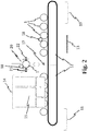
- Fig. 2 shows a side view of a device according to the invention with a pressure bottle 1 already raised at the filling position 17.
- the conveyor belt can also consist of several parts. It is entirely possible that the manipulator 20 lifts the pressure bottle 1 from a first conveyor belt 12 and, after the filling process, places it on a second conveyor belt 12, which does not necessarily have to run in exactly the same direction as the first conveyor belt 12, provided that the manipulator 20 can perform not only translational movements, but also rotations.
- the manipulator 20 it does not matter whether one or more conveyor belts 12 are used.
- the conveyor belts 12 do not necessarily have to be belts in the actual sense, but can consist of links or other movement systems known in conveyor technology. Some of these known conveyor systems already rotate cylindrical bodies such as pressure bottles 1 during the transport process, which is quite desirable for the present invention in order to even out the temperature and possibly to achieve a mixing of the contents. If the transport system 12 used does not itself produce sufficient rotation of the pressure bottles 1, a rotation mechanism 18 can be provided at one or more points. In particular, the manipulator 20 can be equipped with a rotation mechanism. As in Fig.
- a loading zone 11 in which, possibly with manual assistance, pressure bottles 1 to be filled are placed one behind the other on the conveyor belt, in such a way that their longitudinal axes 2 are each horizontal and transverse to a direction of movement 13 of the conveyor belt 12 run.
- the pressure bottles 1 then pass through a temperature control section 14, in the present exemplary embodiment, a schematically indicated cooling tunnel 15, where they are brought to a desired temperature, which can be higher or lower than the inlet temperature of the pressure bottles 1. In general, it will be a matter of cooling to approx. 15 ° C, for example.
- each pressure bottle 1 gradually reaches the position 17, where it can be gripped by the manipulator 20 and pressed against a filling head 5, not shown here, for the further filling process.
- the manipulator 20 has a first 21 and a second 22 temperature sensor for monitoring the entire filling process, which monitor the temperature profile in the pressure bottle 1 during and after the filling process. It can be, for example, infrared sensors that record the temperature profile on the surface of the pressure bottle 1 relatively precisely and can thus make irregularities during filling or leakages after filling recognizable.
- the manipulator 20 places the pressure bottle 1 back on the same or another conveyor belt 12, from where the pressure bottles 1 are guided to an unloading zone 19, in which they are removed from the conveyor belt 12, possibly with manual assistance, and transported away and stored become.
- Fig. 3 shows in an enlarged representation the essential parts of a filling head, which is fixedly attached to a holding frame 29 in the present invention.
- the filling head differs mainly in its horizontal orientation from filling heads known per se and contains an activation pin 9 for actuating check valves in pressure bottles.
- the filling head 5 can be equipped with different adapters 10 for different pressure bottles, whereby the activation pin 9, which is to be regarded as a wear part anyway, can also be designed to be exchangeable.
- the filling head has various lines 28 for connection to a storage and metering system 7 and at least one sensor connection 6, in the present exemplary embodiment two, for connecting sensors for measuring pressure and / or temperature of the filling gas.
- FIG. 4 shows a schematic view from above how several conveyor belts 12 can be arranged parallel to one another and jointly pass through a temperature control section 14, for example a cooling tunnel 16.
- the filling position for all pressure bottles 1 is located behind the cooling tunnel 16, with three manipulators 20 for lifting the pressure bottles 1 being present in this exemplary embodiment.
- Such an arrangement has the advantage of increasing the capacity for filling pressure bottles 1 to triple without triple effort in the loading zone 11, in the cooling tunnel 14, in the storage and dosing system at the filling position 17 and in the unloading zone 19 are required.
- the same systems can be used for all conveyor belts in these areas.
- the present invention is particularly suitable for pressure bottles with volumes of up to 20 l and for the bulk filling of such pressure bottles with gases such as oxygen, nitrogen, helium or argon or argon mixtures.
- Pressure bottles which can be filled particularly well with the system according to the invention, are in circulation in large numbers under the trade name ALbee and are used in many places around the world.
- the invention enables automated, safe and logistically simple and fast filling with short throughput times for the filling process.
Landscapes
- Engineering & Computer Science (AREA)
- Mechanical Engineering (AREA)
- General Engineering & Computer Science (AREA)
- Filling Of Jars Or Cans And Processes For Cleaning And Sealing Jars (AREA)
Description
- Die vorliegende Erfindung betrifft ein Verfahren und eine Vorrichtung zum seriellen Befüllen einer Vielzahl von Druckflaschen mit einem Gas, wobei es insbesondere um relativ kleine Flaschen mit 2 bis 20 1 (Liter) Inhalt und für Drücke von 100 bis 400 bar geht, insbesondere um Gasflaschen mit 5 1 Inhalt bis 200 bar Innendruck und mit 11 1 Inhalt und 300 bar Innendruck für die Gase Sauerstoff, Stickstoff, Helium, Argon und Mischungen von Argon, die zum Schweißen genutzt werden (sogenanntes "Argon-Mix").
- Die Erfindung ist anwendbar für Druckflaschen, die eine geometrische Längsachse und einen dazu zentrierten Füllstutzen am Kopf aufweisen. Insbesondere sind solche Produkte unter dem Handelsnamen "ALbee" in der Literatur bekannt, wobei solche Druckflaschen bevorzugt einen Sicherheitskopf mit Bedien- und Anschlusselementen für den Benutzer in einem Sicherheitskäfig, der gleichzeitig als Handgriff dienen kann, aufweisen.
- Das Befüllen von entleerten Druckflaschen findet nach dem Stand der Technik an unterschiedlich konstruierten Füllstationen statt. Da es hierbei um einen massenweise auftretenden Vorgang geht, gibt es seit langem Bestrebungen zur Automatisierung, jedoch sind bei der Vorbereitung und Durchführung des Füllvorgangs bisher aus verschiedenen Gründen relativ viele manuelle Eingriffe erforderlich. Im Allgemeinen wird der eigentliche Füllvorgang bei aufrecht stehenden Flaschen durchgeführt, einerseits weil so Füllstutzen und andere Bedienelemente der Druckflaschen für manuelle Eingriffe leicht erreichbar sind und andererseits weil dann auf relativ kleinem Raum viele Druckflaschen gleichzeitig in einem Füllstand untergebracht werden können, meist in sogenannten Paletten angeordnet.
- Für große und schwere Druckflaschen ist es üblich, einen Füllkopf zum Füllstutzen zu führen, was in den meisten Fällen von Hand durchgeführt wird.
- Aus Sicherheitsgründen und zur Automatisierung sind Druckflaschen auch typischerweise mit maschinelesbaren Codierungen versehen, bspw. Bar-Codes, um das Befüllen mit dem richtigen Gas und dem richtigen Druck überprüfen und sicherstellen zu können. Auch hierzu gibt es im Stand der Technik zahlreiche Vorschläge.
- Auch der Aufbau von typischen Füllständen mit Vorratsbehältern verschiedener Gase mit Evakuierungs- und Entlüftungsvorrichtungen sowie Einrichtungen für Spülvorgänge sind zahlreich bekannt, ebenso die Verwendung von Füllköpfen mit Adaptern oder Verstellmöglichkeiten für unterschiedliche Füllstutzen.
- Aus der
DE 197 18 645 A1 sind auch bereits ein Verfahren und eine Vorrichtung zum Befüllen von Druckflaschen bekannt, bei denen eine weitgehende Automatisierung verwirklicht ist, insbesondere beim eigentlichen Füllvorgang, indem Druckflaschen auf einem Transportband transportiert und dann vertikal angehoben und mit ihrem Füllstutzen gegen einen Füllkopf gedrückt werden. Auch bei diesem System wird allerdings der Füllvorgang jeweils bei aufrecht stehenden Druckflaschen durchgeführt. - Ausgehend von dem genannten Stand der Technik liegt der vorliegenden Erfindung die Aufgabe zugrunde, das massenhafte Befüllen von relativ kleinen Druckflaschen bis zu 20 1 Volumen zu vereinfachen und zu verbessern und wesentliche Schritte dabei zu automatisieren, wobei gleichzeitig die Genauigkeit des Füllvorgangs bezüglich Füllmenge und ggf. Zusammensetzung verbessert werden soll.
- Zur Lösung dieser Aufgaben dienen ein Verfahren nach dem Anspruch 1 und eine Vorrichtung nach dem Anspruch 7. Vorteilhafte Ausgestaltungen, die einzeln oder in technisch sinnvollen Kombinationen miteinander zur Anwendung kommen können, sind in den jeweils abhängigen Ansprüchen angegeben.
- Das erfindungsgemäße Verfahren zum seriellen Befüllen einer Vielzahl von eine geometrische Längsachse und einen dazu zentrierten Füllstutzen aufweisenden Druckflaschen mit einem Gas wird im Wesentlichen an liegenden, also horizontal ausgerichteten Druckflaschen durchgeführt. Dazu werden die Druckflaschen parallel zueinander und mit ihren Längsachsen quer zu einer Transportrichtung ausgerichtet auf einem Transportband angeordnet und von diesem in Transportrichtung bewegt, wobei jede Druckflasche einzeln bei Erreichen einer Füllposition von einem Manipulator angehoben, justiert und horizontal in Richtung ihrer Längsachse zu einem Füllkopf bewegt und an diesen angepresst wird, so dass ein Füllvorgang durchgeführt werden kann. Nach Abschluss des Füllvorgangs wird die Druckflasche zurückbewegt, wieder auf dem selben Transportband oder einem anderen Transportbandabgelegt und weitertransportiert. Dieser Vorgang kann weitestgehend automatisiert werden, so dass manuelle Eingriffe höchstens in einer Beladezone am Anfang des Transportbands und in einer Entladezone am Ende des Transportbands erforderlich sind. In diesen Bereichen kann je nach Art der Anlieferung und Auslieferung der Druckflaschen eine Sortierung, Markierung, Prüfung und sonstige logistische Behandlung der Druckflaschen erfolgen.
- Bei einer besonders vorteilhaften Ausführungsform der Erfindung rotiert der Manipulator nach dem Anheben jede Druckflasche um ihre Längsachse. Dies führt einerseits zu einer genauen Zentrierung und erlaubt andererseits auch das Ablesen eines auf der Druckflasche angebrachten Barcodes mit einem ortsfesten oder an dem Manipulator angebrachten Lesegerät. Eine zusätzliche Rotation nach dem Füllvorgang vor dem Ablegen auf dem Transportband kann eine gleichmäßige Temperaturverteilung begünstigen
- Da diese Vorgänge im Allgemeinen in einer Halle stattfinden, gelegentlich aber auch eine Lagerung außerhalb solcher Hallen erfolgt, kann eine für den Befüllvorgang sinnvolle und reproduzierbare Temperatur, bspw. 15 °C, bei bisherigen Füllvorrichtungen nicht immer sichergestellt werden. In einer besonderen Ausgestaltung der Erfindung ist daher vorgesehen, dass das Transportband mit den Druckflaschen vor Erreichen der Füllposition eine Temperierungsstrecke, insbesondere einen Kühltunntel, durchläuft, in dem die Druckflaschen auf eine gewünschte Fülltemperatur gebracht werden. Im Allgemeinen wird es dabei um eine gewisse Abkühlung der Druckflaschen gehen, da die Umgebungstemperatur in Hallen, die zum Abfüllen genutzt werden, typischerweise höher liegt. In Abhängigkeit von den klimatischen Bedingungen und der Art der Lagerung kann aber durchaus auch eine Erhöhung der Temperatur in der Temperierungsstrecke erforderlich sein. Im Ergebnis verweilen alle zu befüllenden Druckflaschen auf dem Transportband genügend lange in der Temperierungsstrecke, um die gewünschte Fülltemperatur anzunehmen.
- Da die Druckflaschen einzeln und nacheinander befüllt werden, ist typischerweise mit einer relativ langsamen schrittweisen Bewegung des Transportbands zu rechnen, wodurch eine genügende Verweildauer in der Temperierungsstrecke automatisch erreicht wird, sofern diese genügend lang ausgelegt ist.
- Je nach Art des Transportbands, worunter nicht unbedingt ein Band im eigentlichen Sinne, sondern auch bspw. ein System von Transportrollen verstanden wird, behalten die Druckflaschen ihre Lage beim Transport bei oder drehen sich sogar allein durch den Transport schon im ihre Längsachse. Da für die Temperierungsstrecke und/oder für den Transport nach dem Füllvorgang jedenfalls wünschenswert ist, dass die Druckflaschen rotiert werden, um eine gleichmäßige Temperatur und/oder eine gute Durchmischung ihres Inhalts zu erreichen, wird das Transportsystem bevorzugt so ausgelegt oder mit zusätzlichen Mitteln zum Rotieren der Druckflaschen versehen, dass eine gleichmäßige Temperierung und/oder Durchmischung gewährleistet wird. Dies ist ein besonderer Vorteil der Erfindung, da insbesondere bei dem Befüllen von Druckflaschen mit Gasmischungen das liegende Befüllen und eine anschließende Rotation eine genaue Prüfung des Mischungsverhältnisses durch eine Probeentnahmezulassen.
- Erfindungsgemäß kann die Kapazität, das heißt die Zahl der pro Zeiteinheit zu befüllenden Druckflaschen, erhöht werden, indem mehrere Systeme nebeneinander angeordnet werden, wobei entweder mehrere Transportbänder oder ein besonders breites Transportband angewendet werden können. Auch ist nur eine Temperierungsstrecke für mehrere nebeneinander angeordnete Befüllstrecken erforderlich. Insgesamt kann dadurch die Kapazität erhöht werden, ohne dass erhebliche Änderungen an Beladezone, Entladezone und Temperierungsstrecke vorgesehen werden müssen. Auch kann ein übliches Vorrats- und Befüllsystem relativ leicht mit mehreren Füllköpfen ausgestattet werden, ohne dass der Aufwand stark ansteigt.
- Eine erfindungsgemäße Vorrichtung zum seriellen Befüllen einer Vielzahl von eine geometrische Längsachse und einen dazu zentrierten Füllstutzen aufweisenden Druckflaschen mit einem Gas weist folgendes auf:
- ein Transportband, auf dem die Druckflaschen liegend und mit ihren Längsachsen quer zu einer Transportrichtung ausgerichtet transportierbar sind,
- einen Manipulator, mit dem jede Druckflasche einzeln bei Erreichen einer Füllposition angehoben, um ihre Längsachse rotiert und in einer vorgebbaren Lage justiert werden kann,
- eine Andrückvorrichtung, mit der die Druckflasche in der vorgebbaren Lage in Richtung ihrer Längsachse und zurück bewegbar und mit ihrem Füllstutzen an einen Füllkopf anpressbar ist und
- einen Füllkopf zur Befüllung der Druckflasche mit einem Gas oder Gasgemisch.
- Mit einer solchen Vorrichtung lässt sich das oben beschriebene Verfahren durchführen. Da die Druckflaschen, um die es bei der vorliegenden Erfindung geht, ein verhältnismäßige geringes Gewicht aufweisen, müssen an den Manipulator und die Andrückvorrichtung keine besonderen Anforderungen bezüglich ihrer Struktur und mechanischen Eigenschaften gestellt werden und auch die Halterung für den Füllkopf ist mechanisch einfach zu verwirklichen.
- Bevorzugt weist die Vorrichtung um das Transportband herum eine Temperierungsstrecke, insbesondere einen Kühltunnel auf, die von dem Transportband und den Druckflaschen vor Erreichen der Füllposition durchlaufen wird. Sofern es um eine Kühlung geht, können hier Verdampfer von flüssigem Stickstoff und ähnliche Mittel zur wirksamen Kühlung eingesetzt werden.
- Sofern das Transportband nicht konstruktionsbedingt die Druckflaschen beim Transport rotiert, so sollen vorzugsweise Mittel zum Rotieren der Druckflaschen um ihre Längsachse vorhanden sein. Dadurch werden eine gleichmäßige Temperierung der Druckflaschen vor dem Befüllen und/oder eine gute Durchmischung und gleichmäßige Temperierung nach dem Befüllen erreicht.
- In einer besonderen Ausgestaltung kann das Transportband so breit sein oder aus einer Mehrzahl von Transportbändern so ausgebildet sein, dass zwei oder mehr Druckflaschen in ihrer Längsrichtung etwa fluchtend hintereinander angeordnet quer zur Transportrichtung aufgenommen und transportiert werden können, insbesondere durch eine gemeinsame Temperierungsstrecke, wobei an der Füllposition eine entsprechende Anzahl von Füllköpfen vorhanden ist, zu denen die zwei oder mehr Druckflaschen angehoben und geführt werden können. Wie oben bereits beschrieben, führt dies zu einer Erhöhung der Kapazität der Anlage mit relativ geringem Aufwand.
- Dadurch, dass erfindungsgemäß die Druckflaschen zum Füllkopf bewegt werden, kann jeder Füllkopf ortsfest angeordnet sein und über Ventile mit mindestens einem Vorratsbehälter für das mindestens eine zu füllende Gas verbunden sein. Vorzugsweise ist der Füllkopf mit leicht auswechselbaren Verschleißteilen ausgerüstet und erlaubt das Anbringen verschiedener Adapter für Druckflaschen unterschiedlicher Fülllung oder unterschiedlichen Drucks.
- In einer bevorzugten Ausführungsform der Erfindung weist der Füllkopf mindestens einen Sensoranschluss auf, insbesondere für Temperatur und/oder Druck in Leitungen des Füllkopfs. Dies erlaubt eine gute Kontrolle und Regelung des Füllvorgangs, indem Druck und/oder Temperatur bzw. deren Verläufe während des Füllvorgangs gemessen werden.
- Für eine automatisierte Befüllung und eine ökonomischen Einsatz von Druckflaschen ist es besonders vorteilhaft, wenn jeder Füllstutzen (meist in einer für andere Zwecke vorhandenen Armatur eingebaut) der Druckflaschen ein aktives Rückschlagventil aufweist. Zunächst wird so ein Rückschlagventil beim Anpressen gegen den Füllkopf durch einen geeigneten Aktivierungsstift geöffnet, so dass der Füllvorgang durchgeführt werden kann. Nach dem Füllvorgang wird der Aktivierungsstift zurückgezogen, was z. B. pneumatisch erfolgen kann. Das aktive Rückschlagventil wird dann aufgrund einer Federbelastung und des Innendruckes in der Druckflasche sofort geschlossen. Die Druckflasche kann dann zurückgezogen und wieder auf dem Transportband abgelegt werden.
- Bei einer weiteren bevorzugten Ausführungsform der Erfindung weist der Manipulator mindestens einen Temperatursensor auf, vorzugsweise einen Infrarotsensor, mit dem vor, während und/oder nach dem Füllvorgang die Temperatur und/oder der Temperaturverlauf der Druckflasche messbar sind. Da die Außentemperatur der Druckflasche relativ schnell der Temperatur im Inneren folgt, lassen sich der Füllvorgang und die damit einhergehenden Temperaturänderungen auf diese Weise berührungslos verfolgen, was eine gute Kontrolle des Füllvorgangs erlaubt. Auch Gasverluste nach dem Füllvorgang können auf diese Weise detektiert werden, weil ein Druckabfall auch eine Absenkung der Flaschentemperatur bewirkt.
- Die vorliegende Patentanmeldung ist besonders auf die Abfüllung von mindestens einem Gas oder einer Gasmischung aus der Gruppe Sauerstoff, Argon, Stickstoff, Helium, Wasserstoff und Argongemische, wie sie insbesondere zum Schweißen benutzt werden, anwendbar. Bei geeigneten Sicherheitseinrichtungen, bei denen insbesondere die Gasarterkennung durch Barcodes an den Druckflaschen erfolgt, kann ein Füllkopf für verschiedene Gasarten benutzt werden, indem Ventile zu unterschiedlichen Vorratsbehältern freigeschaltet werden.
- Im Folgenden wird die Erfindung anhand von Ausführungsbeispielen, auf die die Erfindung jedoch nicht beschränkt ist, näher erläutert. Es zeigen:
- Fig. 1:
- ein schematisch dargestelltes Ausführungsbeispiel der Erfindung in Transportrichtung der Druckflaschen gesehen,
- Fig. 2:
- eine schematische Seitenansicht der
Fig. 1 , - Fig. 3:
- einen erfindungsgemäßen Füllkopf, und
- Fig. 4:
- eine Ansicht von oben auf ein erfindungsgemäßes System mit Kühltunnel, durch den drei erfindungsgemäße Transportbänder verlaufen.
-
Fig. 1 zeigt in schematischer Darstellung die Konstellation einer erfindungsgemäßen Vorrichtung in der Ebene einer Füllposition 17 für Druckflaschen 1. Eine Druckflasche 1 mit einer geometrischen Längsachse 2 und einem Füllstutzen 3, der über ein aktives Rückschlagventil 4 mit dem Innenvolumen der Druckflasche 1 kommuniziert, liegt dabei auf einem Transportband 12. Die Druckflasche 1 kann von einem Manipulator 20 von oben ergriffen und bei weiterhin horizontal liegender Längsachse 2 angehoben werden. Pfeile deuten die möglichen Bewegungen des Manipulators 20 an. Bevorzugt kann der Manipulator 20 die Druckflasche 1 auch um ihre Längsachse 2 rotieren, was zur Zentrierung der Längsachse hilfreich ist und ein gleichzeitiges Ablesen eines Barcodes an der Druckflasche mit einem nicht dargestellten Lesegerät erlaubt. Insbesondere kann die Druckflasche 1 soweit angehoben werden, dass ihre Längsachse 2 mit einem Füllkopf 5 fluchtet. In dieser Lage kann die Druckflasche 1 von einer Andrückvorrichtung 23, bspw. mittels eines durch eine Druckfeder 24 federbelasteten Stempels 30, gegen den Füllkopf 5 gedrückt werden. Der Stempel 30 und somit auch die Druckflasche 1 werden mit Federkraft gegen den Füllkopf 5 gepresst. Dies dient der Sicherheit für den Fall, dass während des Füllvorganges die Steuerluft für die Andrückvorrichtung 23 ausfallen würde. Die Anpresskraft bleibt durch die Druckfeder 24 in jedem Fall erhalten. Mit der Druckluft wird gegen die Federkraft der Stempel und somit auch die Flasche wieder zurückgezogen. Dazu weist die Andrückvorrichtung 23 eine Vorschubeinrichtung 25 auf, die bspw. mittels Pressluft betätigt werden kann. Eine Druckfeder 24 dämpft die Vorschubeinrichtung 25 und unterstützt eine Rückzieheinrichtung 24, die ebenfalls durch Pressluft betätigt werden kann. Damit die Druckflasche 1 zurückgezogen werden kann, muss der Stempel 30 so ausgestaltet sein, dass er die Druckflasche entweder an ihrem hinteren Ende greifen oder aber bspw. magnetisch anziehen kann. Die Bewegungsmöglichkeiten der Andrückvorrichtung 23 sind ebenfalls durch einen Pfeil angedeutet. Wird die Druckflasche 1 gegen den Füllkopf 5 gepresst, so wird, wie bei anderen Fülleinrichtungen auch, das Rückschlagventil 4 mittels eines vorzugsweise pneumatisch betätigbaren Aktivierungsstifts 9 geöffnet, so dass alle für den Füllvorgang erforderlichen Mittel wie Evakuieren, Spülen, neu Befüllen etc. durchgeführt werden können. Dazu ist der Füllkopf 5 über Leitungen 28 mit einem Vorrats- und Dosiersystem 7 verbunden, welches einen oder mehrere Vorratsbehälter 8 für die zu füllenden Gase enthält. Der Füllkopf 5 weist außerdem die erforderlichen Ventile 27 und bei Bedarf Sensoranschlüsse 6 für Temperatur- und/oder Drucksensoren auf. Füllkopf 5, Manipulator 20 und Andrückvorrichtung 23 sind an einem stabilen Halterahmen 29 befestigt. Das dargestellte System kann in der Füllposition 17 weitgehend automatisiert betrieben werden, so dass bei dem eigentlichen Füllvorgang keine manuellen Eingriffe erforderlich sind. Übliche Sicherheitssysteme, bei denen bspw. die Druckflaschen 1 mittels maschinenlesbarer Codierungen, bspw. Bar-Codes, gekennzeichnet sind, können auch hier angewendet werden, um sicherzustellen, dass die Druckflaschen 1 mit dem jeweils gewünschten Gas oder Gasgemisch und unter dem gewünschten Druck befüllt werden. -
Fig. 2 zeigt eine Seitenansicht einer erfindungsgemäßen Vorrichtung mit einer an der Füllposition 17 bereits angehobenen Druckflasche 1. Wie erkennbar ist, ist es nicht zwingend erforderlich, aber durchaus möglich und wünschenswert, dass die Druckflaschen 1 auf nur einem einzigen Transportband 12 bewegt werden. Wie in diesem Ausführungsbeispiel durch eine gestrichelte Linie angedeutet, kann das Transportband auch aus mehreren Teilen bestehen. Es ist durchaus möglich, dass der Manipulator 20 die Druckflasche 1 von einem ersten Transportband 12 anhebt und nach dem Füllvorgang auf einem zweiten Transportband 12 absetzt, welches auch nicht notwendigerweise exakt in der gleichen Richtung verlaufen muss wie das erste Transportband 12, sofern der Manipulator 20 nicht nur translatorische Bewegungen, sondern auch Drehungen durchführen kann. Für die weitere Beschreibung der Erfindung spielt es aber keine Rolle, ob ein oder mehrere Transportbänder 12 eingesetzt werden. Wichtig ist auch, dass die Transportbänder 12 nicht notwendigerweise Bänder im eigentlichen Sinne sein müssen, sondern aus Gliedern oder anderen in der Fördertechnik bekannten Bewegungssystemen bestehen können. Manche dieser bekannten Fördersysteme rotieren bereits durch den Transportvorgang zylindrische Körper wie Druckflaschen 1, was für die vorliegende Erfindung durchaus erwünscht ist, um eine Vergleichmäßigung der Temperatur und eventuell eine Durchmischung des Inhalts zu erreichen. Falls das eingesetzte Transportsystem 12 selbst keine genügende Rotation der Druckflaschen 1 bewirkt, kann an einer oder mehreren Stellen ein Rotationsmechanismus 18 vorgesehen werden. Insbesondere kann der Manipulator 20 mit einem Rotationsmechanismus ausgestattet sein. Wie inFig. 2 schematisch angedeutet ist, liegt an einem Ende des Transportbands 12 eine Beladezone 11, in der, ggf. mit manueller Unterstützung, zu befüllende Druckflaschen 1 hintereinander auf das Transportband gelegt werden, und zwar so, dass ihre Längsachsen 2 jeweils horizontal und quer zu einer Bewegungsrichtung 13 des Transportbands 12 verlaufen. Anschließend durchlaufen die Druckflaschen 1 eine Temperierungsstecke 14, im vorliegenden Ausführungsbeispiel, einen schematisch angedeuteten Kühltunnel 15, wobei sie auf eine gewünschte Temperatur gebracht werden, die höher oder niedriger als die Eingangstemperatur der Druckflaschen 1 sein kann. Im Allgemeinen wird es sich um eine Kühlung auf bspw. ca. 15 °C handeln. Hinter der Temperierungsstrecke 14 gelangt bei weiterem Vorschub nach und nach jede Druckflasche 1 in die Position 17, wo sie von dem Manipulator 20 ergriffen und für den weiteren Füllvorgang an einen hier nicht dargestellten Füllkopf 5 gedrückt werden kann. Der Manipulator 20 weist im vorliegenden Ausführungsbeispiel zur Überwachung des gesamten Füllvorgangs einen ersten 21 und einen zweiten 22 Temperatursensor auf, die den Temperaturverlauf in der Druckflasche 1 während und nach dem Füllvorgang überwachen. Es kann sich bspw. um Infrarotsensoren handeln, die relativ genau den Temperaturverlauf an der Oberfläche der Druckflasche 1 aufzeichnen und damit Unregelmäßigkeiten beim Befüllen oder Leckagen nach dem Befüllen erkennbar machen können. - Nach dem Füllvorgang legt der Manipulator 20 die Druckflasche 1 wieder auf demselben oder einem anderen Transportband 12 ab, von wo die Druckflaschen 1 zu einer Entladezone 19 geführt werden, in der sie, ggf. mit manueller Unterstützung, vom Transportband 12 genommen und abtransportiert und gelagert werden.
-
Fig. 3 zeigt in vergrößerter Darstellung die wesentlichen Teile eines Füllkopfs, der bei der vorliegenden Erfindung ortsfest an einem Halterahmen 29 befestigt ist. Der Füllkopf unterscheidet sich hauptsächlich durch seine horizontale Ausrichtung von an sich bekannten Füllköpfen und enthält einen Aktivierungsstift 9 zur Betätigung von Rückschlagventilen in Druckflaschen. Für unterschiedliche Druckflaschen kann der Füllkopf 5 mit unterschiedlichen Adaptern 10 ausgestattet sein, wobei auch der Aktivierungsstift 9, der ohnehin als Verschleißteil zu betrachten ist, auswechselbar gestaltet sein kann. Der Füllkopf weist verschiedene Leitungen 28 zur Verbindung mit einem Vorrats- und Dosiersystem 7 auf und mindestens einen Sensoranschluss 6, im vorliegenden Ausführungsbeispiel zwei, für den Anschluss von Sensoren zur Messung von Druck und/oder Temperatur des Füllgases. - Schließlich zeigt
Fig. 4 in einer schematischen Ansicht von oben, wie mehrere Transportbänder 12 parallel nebeneinander angeordnet werden können und gemeinsam eine Temperierungsstrecke 14, bspw. einen Kühltunnel 16, durchlaufen. Hinter dem Kühltunnel 16 befindet sich für alle Druckflaschen 1 die Füllposition, wobei in diesem Ausführungsbeispiel drei Manipulatoren 20 zum Anheben der Druckflaschen 1 vorhanden sind. Eine solche Anordnung hat den Vorteil, die Kapazität zum Abfüllen von Druckflaschen 1 zu verdreifachen, ohne dass dreifacher Aufwand in der Beladezone 11, im Kühltunnel 14, bei dem Vorrats- und Dosiersystem an der Füllposition 17 und in der Entladezone 19 erforderlich sind. In diesen Bereichen können für alle Transportbänder die selben Systeme benutzt werden. - Die vorliegende Erfindung eignet sich insbesondere für Druckflaschen mit Volumina bis 20 1 und für das massenhafte Abfüllen solcher Druckflaschen mit Gasen wie Sauerstoff, Stickstoff, Helium oder Argon bzw. Argongemischen. Druckflaschen, die mit dem erfindungsgemäßen System besonders gut befüllt werden können, sind in großer Zahl unter dem Handelsnamen ALbee in Umlauf und werden an vielen Stellen weltweit eingesetzt. Die Erfindung ermöglicht eine automatisierte, sichere und logistisch einfache und schnelle Befüllung mit geringen Durchlaufzeiten für den Füllvorgang.
-
- 1
- Druckflasche
- 2
- Geometrische Längsachse
- 3
- Füllstutzen
- 4
- Aktives Rückschlagventil
- 5
- Füllkopf
- 6
- Sensoranschluss
- 7
- Vorrats- und Dosiersystem
- 8
- Vorratsbehälter
- 9
- Aktivierungsstift
- 10
- Adapter
- 11
- Beladezone
- 12
- Transportband
- 13
- Transportrichtung
- 14
- Temperierungsstrecke
- 15
- Temperierungseinrichtung
- 16
- Kühltunnel
- 17
- Füllposition
- 18
- Rotationsmechanismus
- 19
- Entladezone
- 20
- Manipulator
- 21
- Erster Temperatursensor
- 22
- Zweiter Temperatursensor
- 23
- Andrückvorrichtung
- 24
- Druckfeder
- 25
- Vorschubeinrichtung
- 26
- Rückzieheinrichtung
- 27
- Ventil
- 28
- Leitung
- 29
- Halterahmen
- 30
- Stempel
Claims (15)
- Verfahren zum seriellen Befüllen einer Vielzahl von eine geometrische Längsachse (2) und einen dazu zentrierten Füllstutzen (3) aufweisenden Druckflaschen (1) mit einem Gas, wobei die Druckflaschen (1) parallel zueinander und mit ihren Längsachsen (2) quer zu einer Transportrichtung (13) ausgerichtet auf einem Transportband (12) angeordnet und von diesem in Transportrichtung (13) bewegt werden, wobei jede Druckflasche (1) einzeln bei Erreichen einer Füllposition (17) von einem Manipulator (20) angehoben, justiert und in Richtung ihrer Längsachse (2) zu einem Füllkopf (5) bewegt und an diesen angepresst wird, so dass ein Füllvorgang durchgeführt werden kann, und wobei nach Abschluss des Füllvorganges die Druckflasche (2) zurückbewegt, wieder auf dem Transportband (12) abgelegt und weiter transportiert wird, dadurch gekennzeichnet, daß jede Druckflasche horizontal zu dem Füllkopf bewegt wird.
- Verfahren nach Anspruch 1, wobei der Manipulator (20) jede Druckflasche (1) vor dem Andrücken an den Füllkopf (5) um ihre Längsachse (2) rotiert.
- Verfahren nach Anspruch 1 oder 2, wobei das Transportband (12) mit den Druckflaschen (1) vor Erreichen der Füllposition (17) eine Temperierungsstrecke (14) durchläuft, in der die Druckflaschen (1)auf eine gewünschte Fülltemperatur gebracht werden.
- Verfahren nach Anspruch 1, 2 oder 3, wobei das Beladen und/oder Entladen des Transportbandes (12) manuell oder mit manueller Unterstützung erfolgt, der Füllvorgang jedoch vollautomatisch ohne manuelle Eingriffe.
- Verfahren nach einem der vorhergehenden Ansprüche, wobei die Druckflaschen (1) vor und/oder nach dem Füllvorgang auf dem Transportband (12) um ihre Längsachse (2) rotiert werden, um eine gleichmäßige Temperatur und/oder eine gute Durchmischung ihres Inhaltes zu erreichen.
- Verfahren nach einem der vorhergehenden Ansprüche, wobei jeweils zwei oder mehr Druckflaschen (1) mit ihren Längsachsen (2) etwa fluchtend quer auf mindestens einem Transportband (12) angeordnet werden, so dass zwei oder mehr parallel laufende Reihen von gleichen oder unterschiedlichen Druckflaschen (1) gebildet werden, von denen eine entsprechende Anzahl gleichzeitig von mindestens einem Manipulator (20) angehoben und zu einer entsprechenden Anzahl von gleichen oder unterschiedlichen Füllköpfen (5) geführt werden kann.
- Vorrichtung zum seriellen Befüllen einer Vielzahl von eine geometrische Längsachse (2) und einen dazu zentrierten Füllstutzen (3) aufweisenden Druckflaschen (1) mit einem Gas aufweisend:- ein Transportband (12), auf dem die Druckflaschen (1) liegend und mit ihren Längsachsen (2) quer zu einer Transportrichtung (13) ausgerichtet transportierbar sind,- einen Manipulator (20), mit dem jede Druckflasche (1) einzeln bei Erreichen einer Füllposition (17) angehoben, um ihre Längsachse (2) rotiert und in einer vorgebbaren Lage justiert werden kann,- eine Andrückvorrichtung (23), mit der die Druckflasche (1) in der vorgebbaren Lage in Richtung ihrer Längsachse (2) und zurück bewegbar und mit ihrem Füllstutzen an einen Füllkopf (5) anpressbar ist und- einen Füllkopf (5) zur Befüllung der Druckflasche (1) mit einem Gas oder Gasgemisch.
- Vorrichtung nach Anspruch 7, wobei eine Temperierungsstrecke (14), insbesondere ein Kühltunnel (16), vorhanden ist, die von dem Transportband (12) und den Druckflaschen (1) vor Erreichen der Füllposition (17) durchlaufen wird.
- Vorrichtung nach Anspruch 7 oder 8, wobei Mittel (18) zum Rotieren der Druckflaschen (1) um ihre Längsachse (2) auf dem Transportband (12) vorhanden sind.
- Vorrichtung nach einem der Ansprüche 7 bis 9, wobei das Transportband (12) so breit ist oder eine Mehrzahl von Transportbändern (12) vorhanden ist, dass zwei oder mehr Druckflaschen (1) in ihrer Längsrichtung (2) etwa fluchtend hintereinander angeordnet quer zur Transportrichtung (13) aufgenommen und transportiert werden können, insbesondere durch eine gemeinsame Temperierungsstrecke (14), wobei an der Füllposition (17) eine entsprechende Anzahl von Füllköpfen (5) vorhanden ist, zu denen die zwei oder mehr Druckflaschen (1) angehoben und geführt werden können.
- Vorrichtung nach einem der Ansprüche 7 bis 10, wobei jeder Füllkopf (5) ortsfest angeordnet ist und über Ventile (27) mit mindestens einem Vorratsbehälter (8) für das mindestens eine zu füllende Gas verbunden ist, vorzugsweise mit leicht auswechselbaren Verschleißteilen oder Adaptern (10) versehen ist.
- Vorrichtung nach einem der Ansprüche 7 bis 11, wobei der Füllkopf (5) mindestens einen Sensoranschluss (6), insbesondere für Temperatur und/oder Druck in Leitungen (28) des Füllkopfes (5), aufweist.
- Vorrichtung nach einem der Ansprüche 7 bis 12, wobei jeder Füllstutzen (3) ein aktives Rückschlagventil (4) aufweist.
- Vorrichtung nach einem der Ansprüche 7 bis 13, wobei der Manipulator (20) mindestens einen Temperatursensor (21, 22), vorzugsweise einen Infrarotsensor, aufweist, mit dem vor, während und/oder nach dem Füllvorgang die Temperatur und/oder der Temperaturverlauf der Druckflasche (1) messbar sind.
- Vorrichtung nach einem der Ansprüche 7 bis 14 zur Abfüllung von mindestens einem Gas oder Gemischen aus der Gruppe Sauerstoff, Argon, Stickstoff, Helium, Wasserstoff.
Priority Applications (1)
| Application Number | Priority Date | Filing Date | Title |
|---|---|---|---|
| EP14151735.9A EP2896870B1 (de) | 2014-01-20 | 2014-01-20 | Verfahren und Vorrichtung zum automatischen seriellen Befüllen von Druckflaschen mit Gas |
Applications Claiming Priority (1)
| Application Number | Priority Date | Filing Date | Title |
|---|---|---|---|
| EP14151735.9A EP2896870B1 (de) | 2014-01-20 | 2014-01-20 | Verfahren und Vorrichtung zum automatischen seriellen Befüllen von Druckflaschen mit Gas |
Publications (2)
| Publication Number | Publication Date |
|---|---|
| EP2896870A1 EP2896870A1 (de) | 2015-07-22 |
| EP2896870B1 true EP2896870B1 (de) | 2021-03-17 |
Family
ID=49955999
Family Applications (1)
| Application Number | Title | Priority Date | Filing Date |
|---|---|---|---|
| EP14151735.9A Active EP2896870B1 (de) | 2014-01-20 | 2014-01-20 | Verfahren und Vorrichtung zum automatischen seriellen Befüllen von Druckflaschen mit Gas |
Country Status (1)
| Country | Link |
|---|---|
| EP (1) | EP2896870B1 (de) |
Families Citing this family (5)
| Publication number | Priority date | Publication date | Assignee | Title |
|---|---|---|---|---|
| CN109099307B (zh) * | 2018-07-05 | 2021-02-02 | 常州信息职业技术学院 | 一种液化天然气瓶供气装置 |
| CN109373180B (zh) * | 2018-11-07 | 2021-03-30 | 远军热能动力科技有限公司 | 一种防爆充气装置 |
| CN109373181A (zh) * | 2018-11-07 | 2019-02-22 | 远军热能动力科技有限公司 | 一种管件充气装置 |
| DE102020203342B4 (de) * | 2020-03-16 | 2025-01-09 | Sielaff GmbH & Co. KG Automatenbau Herrieden | Kopplungsvorrichtung zur automatischen Kopplung eines Druckgasbehälters sowie Automat und Verfahren zum automatischen Befüllen eines Druckgasbehälters |
| DE202020105437U1 (de) | 2020-09-23 | 2022-01-05 | Markus Mayer | Füllanlage |
Family Cites Families (7)
| Publication number | Priority date | Publication date | Assignee | Title |
|---|---|---|---|---|
| DE2129548A1 (de) * | 1970-06-16 | 1971-12-23 | Altalanos Geptervezoe Iroda | Vorrichtung zur automatischen Fuellung von Gaspatronen |
| US4567923A (en) * | 1985-02-15 | 1986-02-04 | John R. Nalbach Engineering Co., Inc. | Apparatus for filling tanks with liquefied gas |
| FR2682080B1 (fr) * | 1991-10-02 | 1994-01-14 | Butagaz | Procede de manutention automatique de bouteilles de grande capacite, en particulier de gaz liquefie, et installation pour la mise en óoeuvre du procede. |
| DE19718645A1 (de) | 1997-05-02 | 1998-11-12 | Tilke Gmbh | Verfahren und Vorrichtung zum Befüllen von Gasflaschen |
| DE10115334A1 (de) * | 2001-03-28 | 2002-10-02 | Karl-Peter Hasenkopf | Kombi- Verkaufssystem für Gase |
| ES2211285B1 (es) * | 2002-05-16 | 2005-03-16 | Sociedad Española De Carburos Metalicos, S.A. | Procedimiento e instalacion para el llenado de botellas con gas. |
| EP1813853B1 (de) * | 2006-01-27 | 2009-05-13 | L'AIR LIQUIDE, Société Anonyme pour l'Etude et l'Exploitation des Procédés Georges Claude | Hochdruckgasbehälter mit Zusatzventil und Verfahren zu dessen Befüllung |
-
2014
- 2014-01-20 EP EP14151735.9A patent/EP2896870B1/de active Active
Non-Patent Citations (1)
| Title |
|---|
| None * |
Also Published As
| Publication number | Publication date |
|---|---|
| EP2896870A1 (de) | 2015-07-22 |
Similar Documents
| Publication | Publication Date | Title |
|---|---|---|
| EP2207019B1 (de) | Wägegutträger für eine Waage | |
| DE2335806A1 (de) | Abfuell- und pruefverfahren | |
| EP2896870A1 (de) | Verfahren und Vorrichtung zum automatischen seriellen Befüllen von Druckflaschen mit Gas | |
| EP2702386A1 (de) | Stanzvorrichtung mit greifeinheit | |
| DE102014114298A1 (de) | Behälterbehandlungsvorrichtung | |
| EP2492238A1 (de) | Vorrichtung zum Verschließen von Behältern | |
| DE29608120U1 (de) | Vorrichtung zum Manipulieren von mit Barcodes versehenen Probenröhrchen | |
| DE19718645A1 (de) | Verfahren und Vorrichtung zum Befüllen von Gasflaschen | |
| WO2011047936A1 (de) | VORRICHTUNG ZUM BEFÜLLEN UND VERSCHLIEßEN VON BEHÄLTNISSEN | |
| DE2657987A1 (de) | Vorrichtung zum transport von saecken oder aehnlichen behaeltern von einer fuellstation zu weiteren stationen | |
| DE102005062715B4 (de) | Vorrichtung zum Befüllen von Aufnahmebehältern mit den Produkten einer Rundläuferpresse | |
| DE3045145C2 (de) | Vorrichtung zum Greifen und anschließenden Entleeren eines oben offenen Behälters in einen Aufnahmebehälter | |
| DE2538710C3 (de) | Umsetzvorrichtung für Flaschen o.dgl. Behälter | |
| AT398854B (de) | Zwischenträgerstück | |
| DE202005020225U1 (de) | Transporteinrichtung | |
| DE3128930C2 (de) | ||
| DE1925159C3 (de) | Greifervorrichtung | |
| DE2603191C2 (de) | Verfahren und Vorrichtung zum Umbinden von Posten von Gegenständen mit Bindematerialien | |
| DE202020105437U1 (de) | Füllanlage | |
| DE2435671B2 (de) | Verfahren und Vorrichtung zum Handhaben und Lagern von länglichen Gegenständen | |
| DE2345893C3 (de) | Vorrichtung zum Entfernen von Kronenkorken von Leerflaschen | |
| EP1868898B1 (de) | Verfahren und vorrichtung zum aussortieren von kappen | |
| DE102013015021A1 (de) | Automatisches Befüllen von Gasflaschen | |
| DE1290478B (de) | Vorrichtung zum Verpacken gefuellter Tuben | |
| DE1760065A1 (de) | Vorrichtung zur Spitzensortierung von Leerhuelsen und gleichzeitigen Anbringung ein- oder mehrfarbiger Garn-,Qualitaets- und Mischungskennzeichen auf Leerhuelsen fuer Ringspinnmaschinen |
Legal Events
| Date | Code | Title | Description |
|---|---|---|---|
| PUAI | Public reference made under article 153(3) epc to a published international application that has entered the european phase |
Free format text: ORIGINAL CODE: 0009012 |
|
| 17P | Request for examination filed |
Effective date: 20140120 |
|
| AK | Designated contracting states |
Kind code of ref document: A1 Designated state(s): AL AT BE BG CH CY CZ DE DK EE ES FI FR GB GR HR HU IE IS IT LI LT LU LV MC MK MT NL NO PL PT RO RS SE SI SK SM TR |
|
| AX | Request for extension of the european patent |
Extension state: BA ME |
|
| 17P | Request for examination filed |
Effective date: 20150923 |
|
| RBV | Designated contracting states (corrected) |
Designated state(s): AL AT BE BG CH CY CZ DE DK EE ES FI FR GB GR HR HU IE IS IT LI LT LU LV MC MK MT NL NO PL PT RO RS SE SI SK SM TR |
|
| 17Q | First examination report despatched |
Effective date: 20160421 |
|
| GRAP | Despatch of communication of intention to grant a patent |
Free format text: ORIGINAL CODE: EPIDOSNIGR1 |
|
| STAA | Information on the status of an ep patent application or granted ep patent |
Free format text: STATUS: GRANT OF PATENT IS INTENDED |
|
| INTG | Intention to grant announced |
Effective date: 20201006 |
|
| RAP1 | Party data changed (applicant data changed or rights of an application transferred) |
Owner name: L'AIR LIQUIDE, SOCIETE ANONYME POUR L'ETUDE ET L'EXPLOITATION DES PROCEDES GEORGES CLAUDE Owner name: AIR LIQUIDE DEUTSCHLAND GMBH |
|
| GRAS | Grant fee paid |
Free format text: ORIGINAL CODE: EPIDOSNIGR3 |
|
| GRAA | (expected) grant |
Free format text: ORIGINAL CODE: 0009210 |
|
| STAA | Information on the status of an ep patent application or granted ep patent |
Free format text: STATUS: THE PATENT HAS BEEN GRANTED |
|
| AK | Designated contracting states |
Kind code of ref document: B1 Designated state(s): AL AT BE BG CH CY CZ DE DK EE ES FI FR GB GR HR HU IE IS IT LI LT LU LV MC MK MT NL NO PL PT RO RS SE SI SK SM TR |
|
| REG | Reference to a national code |
Ref country code: GB Ref legal event code: FG4D Free format text: NOT ENGLISH |
|
| REG | Reference to a national code |
Ref country code: CH Ref legal event code: EP |
|
| REG | Reference to a national code |
Ref country code: DE Ref legal event code: R096 Ref document number: 502014015387 Country of ref document: DE |
|
| REG | Reference to a national code |
Ref country code: IE Ref legal event code: FG4D Free format text: LANGUAGE OF EP DOCUMENT: GERMAN |
|
| REG | Reference to a national code |
Ref country code: AT Ref legal event code: REF Ref document number: 1372566 Country of ref document: AT Kind code of ref document: T Effective date: 20210415 |
|
| REG | Reference to a national code |
Ref country code: LT Ref legal event code: MG9D |
|
| PG25 | Lapsed in a contracting state [announced via postgrant information from national office to epo] |
Ref country code: HR Free format text: LAPSE BECAUSE OF FAILURE TO SUBMIT A TRANSLATION OF THE DESCRIPTION OR TO PAY THE FEE WITHIN THE PRESCRIBED TIME-LIMIT Effective date: 20210317 Ref country code: FI Free format text: LAPSE BECAUSE OF FAILURE TO SUBMIT A TRANSLATION OF THE DESCRIPTION OR TO PAY THE FEE WITHIN THE PRESCRIBED TIME-LIMIT Effective date: 20210317 Ref country code: GR Free format text: LAPSE BECAUSE OF FAILURE TO SUBMIT A TRANSLATION OF THE DESCRIPTION OR TO PAY THE FEE WITHIN THE PRESCRIBED TIME-LIMIT Effective date: 20210618 Ref country code: BG Free format text: LAPSE BECAUSE OF FAILURE TO SUBMIT A TRANSLATION OF THE DESCRIPTION OR TO PAY THE FEE WITHIN THE PRESCRIBED TIME-LIMIT Effective date: 20210617 Ref country code: NO Free format text: LAPSE BECAUSE OF FAILURE TO SUBMIT A TRANSLATION OF THE DESCRIPTION OR TO PAY THE FEE WITHIN THE PRESCRIBED TIME-LIMIT Effective date: 20210617 |
|
| REG | Reference to a national code |
Ref country code: NL Ref legal event code: MP Effective date: 20210317 |
|
| PG25 | Lapsed in a contracting state [announced via postgrant information from national office to epo] |
Ref country code: SE Free format text: LAPSE BECAUSE OF FAILURE TO SUBMIT A TRANSLATION OF THE DESCRIPTION OR TO PAY THE FEE WITHIN THE PRESCRIBED TIME-LIMIT Effective date: 20210317 Ref country code: LV Free format text: LAPSE BECAUSE OF FAILURE TO SUBMIT A TRANSLATION OF THE DESCRIPTION OR TO PAY THE FEE WITHIN THE PRESCRIBED TIME-LIMIT Effective date: 20210317 Ref country code: RS Free format text: LAPSE BECAUSE OF FAILURE TO SUBMIT A TRANSLATION OF THE DESCRIPTION OR TO PAY THE FEE WITHIN THE PRESCRIBED TIME-LIMIT Effective date: 20210317 |
|
| PG25 | Lapsed in a contracting state [announced via postgrant information from national office to epo] |
Ref country code: NL Free format text: LAPSE BECAUSE OF FAILURE TO SUBMIT A TRANSLATION OF THE DESCRIPTION OR TO PAY THE FEE WITHIN THE PRESCRIBED TIME-LIMIT Effective date: 20210317 |
|
| PG25 | Lapsed in a contracting state [announced via postgrant information from national office to epo] |
Ref country code: LT Free format text: LAPSE BECAUSE OF FAILURE TO SUBMIT A TRANSLATION OF THE DESCRIPTION OR TO PAY THE FEE WITHIN THE PRESCRIBED TIME-LIMIT Effective date: 20210317 Ref country code: EE Free format text: LAPSE BECAUSE OF FAILURE TO SUBMIT A TRANSLATION OF THE DESCRIPTION OR TO PAY THE FEE WITHIN THE PRESCRIBED TIME-LIMIT Effective date: 20210317 Ref country code: CZ Free format text: LAPSE BECAUSE OF FAILURE TO SUBMIT A TRANSLATION OF THE DESCRIPTION OR TO PAY THE FEE WITHIN THE PRESCRIBED TIME-LIMIT Effective date: 20210317 Ref country code: SM Free format text: LAPSE BECAUSE OF FAILURE TO SUBMIT A TRANSLATION OF THE DESCRIPTION OR TO PAY THE FEE WITHIN THE PRESCRIBED TIME-LIMIT Effective date: 20210317 |
|
| PG25 | Lapsed in a contracting state [announced via postgrant information from national office to epo] |
Ref country code: IS Free format text: LAPSE BECAUSE OF FAILURE TO SUBMIT A TRANSLATION OF THE DESCRIPTION OR TO PAY THE FEE WITHIN THE PRESCRIBED TIME-LIMIT Effective date: 20210717 Ref country code: SK Free format text: LAPSE BECAUSE OF FAILURE TO SUBMIT A TRANSLATION OF THE DESCRIPTION OR TO PAY THE FEE WITHIN THE PRESCRIBED TIME-LIMIT Effective date: 20210317 Ref country code: RO Free format text: LAPSE BECAUSE OF FAILURE TO SUBMIT A TRANSLATION OF THE DESCRIPTION OR TO PAY THE FEE WITHIN THE PRESCRIBED TIME-LIMIT Effective date: 20210317 Ref country code: PL Free format text: LAPSE BECAUSE OF FAILURE TO SUBMIT A TRANSLATION OF THE DESCRIPTION OR TO PAY THE FEE WITHIN THE PRESCRIBED TIME-LIMIT Effective date: 20210317 Ref country code: PT Free format text: LAPSE BECAUSE OF FAILURE TO SUBMIT A TRANSLATION OF THE DESCRIPTION OR TO PAY THE FEE WITHIN THE PRESCRIBED TIME-LIMIT Effective date: 20210719 Ref country code: ES Free format text: LAPSE BECAUSE OF FAILURE TO SUBMIT A TRANSLATION OF THE DESCRIPTION OR TO PAY THE FEE WITHIN THE PRESCRIBED TIME-LIMIT Effective date: 20210317 |
|
| REG | Reference to a national code |
Ref country code: DE Ref legal event code: R097 Ref document number: 502014015387 Country of ref document: DE |
|
| PLBE | No opposition filed within time limit |
Free format text: ORIGINAL CODE: 0009261 |
|
| STAA | Information on the status of an ep patent application or granted ep patent |
Free format text: STATUS: NO OPPOSITION FILED WITHIN TIME LIMIT |
|
| PG25 | Lapsed in a contracting state [announced via postgrant information from national office to epo] |
Ref country code: DK Free format text: LAPSE BECAUSE OF FAILURE TO SUBMIT A TRANSLATION OF THE DESCRIPTION OR TO PAY THE FEE WITHIN THE PRESCRIBED TIME-LIMIT Effective date: 20210317 Ref country code: AL Free format text: LAPSE BECAUSE OF FAILURE TO SUBMIT A TRANSLATION OF THE DESCRIPTION OR TO PAY THE FEE WITHIN THE PRESCRIBED TIME-LIMIT Effective date: 20210317 |
|
| 26N | No opposition filed |
Effective date: 20211220 |
|
| PG25 | Lapsed in a contracting state [announced via postgrant information from national office to epo] |
Ref country code: SI Free format text: LAPSE BECAUSE OF FAILURE TO SUBMIT A TRANSLATION OF THE DESCRIPTION OR TO PAY THE FEE WITHIN THE PRESCRIBED TIME-LIMIT Effective date: 20210317 |
|
| PG25 | Lapsed in a contracting state [announced via postgrant information from national office to epo] |
Ref country code: IT Free format text: LAPSE BECAUSE OF FAILURE TO SUBMIT A TRANSLATION OF THE DESCRIPTION OR TO PAY THE FEE WITHIN THE PRESCRIBED TIME-LIMIT Effective date: 20210317 |
|
| PG25 | Lapsed in a contracting state [announced via postgrant information from national office to epo] |
Ref country code: IS Free format text: LAPSE BECAUSE OF FAILURE TO SUBMIT A TRANSLATION OF THE DESCRIPTION OR TO PAY THE FEE WITHIN THE PRESCRIBED TIME-LIMIT Effective date: 20210717 |
|
| PG25 | Lapsed in a contracting state [announced via postgrant information from national office to epo] |
Ref country code: MC Free format text: LAPSE BECAUSE OF FAILURE TO SUBMIT A TRANSLATION OF THE DESCRIPTION OR TO PAY THE FEE WITHIN THE PRESCRIBED TIME-LIMIT Effective date: 20210317 |
|
| REG | Reference to a national code |
Ref country code: CH Ref legal event code: PL |
|
| GBPC | Gb: european patent ceased through non-payment of renewal fee |
Effective date: 20220120 |
|
| REG | Reference to a national code |
Ref country code: BE Ref legal event code: MM Effective date: 20220131 |
|
| PG25 | Lapsed in a contracting state [announced via postgrant information from national office to epo] |
Ref country code: LU Free format text: LAPSE BECAUSE OF NON-PAYMENT OF DUE FEES Effective date: 20220120 Ref country code: GB Free format text: LAPSE BECAUSE OF NON-PAYMENT OF DUE FEES Effective date: 20220120 |
|
| PG25 | Lapsed in a contracting state [announced via postgrant information from national office to epo] |
Ref country code: BE Free format text: LAPSE BECAUSE OF NON-PAYMENT OF DUE FEES Effective date: 20220131 |
|
| PG25 | Lapsed in a contracting state [announced via postgrant information from national office to epo] |
Ref country code: LI Free format text: LAPSE BECAUSE OF NON-PAYMENT OF DUE FEES Effective date: 20220131 Ref country code: CH Free format text: LAPSE BECAUSE OF NON-PAYMENT OF DUE FEES Effective date: 20220131 |
|
| PG25 | Lapsed in a contracting state [announced via postgrant information from national office to epo] |
Ref country code: IE Free format text: LAPSE BECAUSE OF NON-PAYMENT OF DUE FEES Effective date: 20220120 |
|
| REG | Reference to a national code |
Ref country code: AT Ref legal event code: MM01 Ref document number: 1372566 Country of ref document: AT Kind code of ref document: T Effective date: 20220120 |
|
| PG25 | Lapsed in a contracting state [announced via postgrant information from national office to epo] |
Ref country code: AT Free format text: LAPSE BECAUSE OF NON-PAYMENT OF DUE FEES Effective date: 20220120 |
|
| PG25 | Lapsed in a contracting state [announced via postgrant information from national office to epo] |
Ref country code: HU Free format text: LAPSE BECAUSE OF FAILURE TO SUBMIT A TRANSLATION OF THE DESCRIPTION OR TO PAY THE FEE WITHIN THE PRESCRIBED TIME-LIMIT; INVALID AB INITIO Effective date: 20140120 |
|
| PG25 | Lapsed in a contracting state [announced via postgrant information from national office to epo] |
Ref country code: MK Free format text: LAPSE BECAUSE OF FAILURE TO SUBMIT A TRANSLATION OF THE DESCRIPTION OR TO PAY THE FEE WITHIN THE PRESCRIBED TIME-LIMIT Effective date: 20210317 Ref country code: CY Free format text: LAPSE BECAUSE OF FAILURE TO SUBMIT A TRANSLATION OF THE DESCRIPTION OR TO PAY THE FEE WITHIN THE PRESCRIBED TIME-LIMIT Effective date: 20210317 |
|
| PG25 | Lapsed in a contracting state [announced via postgrant information from national office to epo] |
Ref country code: MT Free format text: LAPSE BECAUSE OF FAILURE TO SUBMIT A TRANSLATION OF THE DESCRIPTION OR TO PAY THE FEE WITHIN THE PRESCRIBED TIME-LIMIT Effective date: 20210317 |
|
| PG25 | Lapsed in a contracting state [announced via postgrant information from national office to epo] |
Ref country code: TR Free format text: LAPSE BECAUSE OF FAILURE TO SUBMIT A TRANSLATION OF THE DESCRIPTION OR TO PAY THE FEE WITHIN THE PRESCRIBED TIME-LIMIT Effective date: 20210317 |
|
| PGFP | Annual fee paid to national office [announced via postgrant information from national office to epo] |
Ref country code: DE Payment date: 20260121 Year of fee payment: 13 |
|
| PGFP | Annual fee paid to national office [announced via postgrant information from national office to epo] |
Ref country code: FR Payment date: 20260123 Year of fee payment: 13 |