EP2895294B1 - Laserbearbeitungsvorrichtung - Google Patents
Laserbearbeitungsvorrichtung Download PDFInfo
- Publication number
- EP2895294B1 EP2895294B1 EP13762129.8A EP13762129A EP2895294B1 EP 2895294 B1 EP2895294 B1 EP 2895294B1 EP 13762129 A EP13762129 A EP 13762129A EP 2895294 B1 EP2895294 B1 EP 2895294B1
- Authority
- EP
- European Patent Office
- Prior art keywords
- deflection
- laser
- machining device
- angle
- laser machining
- Prior art date
- Legal status (The legal status is an assumption and is not a legal conclusion. Google has not performed a legal analysis and makes no representation as to the accuracy of the status listed.)
- Active
Links
- 238000003754 machining Methods 0.000 claims description 24
- 230000003287 optical effect Effects 0.000 claims description 11
- 238000001514 detection method Methods 0.000 claims description 8
- 230000008859 change Effects 0.000 claims description 7
- 238000000034 method Methods 0.000 claims description 6
- 238000010330 laser marking Methods 0.000 claims 2
- 230000004044 response Effects 0.000 description 6
- 239000011248 coating agent Substances 0.000 description 5
- 238000000576 coating method Methods 0.000 description 5
- 238000010586 diagram Methods 0.000 description 5
- 239000000463 material Substances 0.000 description 5
- VYPSYNLAJGMNEJ-UHFFFAOYSA-N Silicium dioxide Chemical compound O=[Si]=O VYPSYNLAJGMNEJ-UHFFFAOYSA-N 0.000 description 4
- 239000000835 fiber Substances 0.000 description 4
- 238000004519 manufacturing process Methods 0.000 description 3
- 238000007493 shaping process Methods 0.000 description 3
- XEEYBQQBJWHFJM-UHFFFAOYSA-N Iron Chemical compound [Fe] XEEYBQQBJWHFJM-UHFFFAOYSA-N 0.000 description 2
- 239000000919 ceramic Substances 0.000 description 2
- 230000008878 coupling Effects 0.000 description 2
- 238000010168 coupling process Methods 0.000 description 2
- 238000005859 coupling reaction Methods 0.000 description 2
- 230000033001 locomotion Effects 0.000 description 2
- 230000008569 process Effects 0.000 description 2
- 230000005855 radiation Effects 0.000 description 2
- 239000005368 silicate glass Substances 0.000 description 2
- 239000007787 solid Substances 0.000 description 2
- 229910019655 synthetic inorganic crystalline material Inorganic materials 0.000 description 2
- LSGOVYNHVSXFFJ-UHFFFAOYSA-N vanadate(3-) Chemical compound [O-][V]([O-])([O-])=O LSGOVYNHVSXFFJ-UHFFFAOYSA-N 0.000 description 2
- 229910001030 Iron–nickel alloy Inorganic materials 0.000 description 1
- 239000006094 Zerodur Substances 0.000 description 1
- GNKTZDSRQHMHLZ-UHFFFAOYSA-N [Si].[Si].[Si].[Ti].[Ti].[Ti].[Ti].[Ti] Chemical compound [Si].[Si].[Si].[Ti].[Ti].[Ti].[Ti].[Ti] GNKTZDSRQHMHLZ-UHFFFAOYSA-N 0.000 description 1
- 239000006096 absorbing agent Substances 0.000 description 1
- 239000011149 active material Substances 0.000 description 1
- 238000004026 adhesive bonding Methods 0.000 description 1
- PNEYBMLMFCGWSK-UHFFFAOYSA-N aluminium oxide Inorganic materials [O-2].[O-2].[O-2].[Al+3].[Al+3] PNEYBMLMFCGWSK-UHFFFAOYSA-N 0.000 description 1
- JNDMLEXHDPKVFC-UHFFFAOYSA-N aluminum;oxygen(2-);yttrium(3+) Chemical compound [O-2].[O-2].[O-2].[Al+3].[Y+3] JNDMLEXHDPKVFC-UHFFFAOYSA-N 0.000 description 1
- 201000009310 astigmatism Diseases 0.000 description 1
- 238000006243 chemical reaction Methods 0.000 description 1
- 238000010276 construction Methods 0.000 description 1
- PMHQVHHXPFUNSP-UHFFFAOYSA-M copper(1+);methylsulfanylmethane;bromide Chemical compound Br[Cu].CSC PMHQVHHXPFUNSP-UHFFFAOYSA-M 0.000 description 1
- 238000005520 cutting process Methods 0.000 description 1
- 230000006378 damage Effects 0.000 description 1
- 230000001419 dependent effect Effects 0.000 description 1
- 238000011161 development Methods 0.000 description 1
- 230000018109 developmental process Effects 0.000 description 1
- 239000002241 glass-ceramic Substances 0.000 description 1
- 230000020169 heat generation Effects 0.000 description 1
- 229910052742 iron Inorganic materials 0.000 description 1
- 230000007257 malfunction Effects 0.000 description 1
- 239000003550 marker Substances 0.000 description 1
- 229910052751 metal Inorganic materials 0.000 description 1
- 239000002184 metal Substances 0.000 description 1
- 238000005459 micromachining Methods 0.000 description 1
- 229910000595 mu-metal Inorganic materials 0.000 description 1
- 230000035699 permeability Effects 0.000 description 1
- 238000005086 pumping Methods 0.000 description 1
- 239000010703 silicon Substances 0.000 description 1
- 229910052710 silicon Inorganic materials 0.000 description 1
- 239000000377 silicon dioxide Substances 0.000 description 1
- 238000005476 soldering Methods 0.000 description 1
- 238000010408 sweeping Methods 0.000 description 1
- 238000007514 turning Methods 0.000 description 1
- 238000003466 welding Methods 0.000 description 1
- 229910019901 yttrium aluminum garnet Inorganic materials 0.000 description 1
Images




Classifications
-
- G—PHYSICS
- G02—OPTICS
- G02B—OPTICAL ELEMENTS, SYSTEMS OR APPARATUS
- G02B26/00—Optical devices or arrangements for the control of light using movable or deformable optical elements
- G02B26/08—Optical devices or arrangements for the control of light using movable or deformable optical elements for controlling the direction of light
- G02B26/10—Scanning systems
- G02B26/105—Scanning systems with one or more pivoting mirrors or galvano-mirrors
-
- B—PERFORMING OPERATIONS; TRANSPORTING
- B23—MACHINE TOOLS; METAL-WORKING NOT OTHERWISE PROVIDED FOR
- B23K—SOLDERING OR UNSOLDERING; WELDING; CLADDING OR PLATING BY SOLDERING OR WELDING; CUTTING BY APPLYING HEAT LOCALLY, e.g. FLAME CUTTING; WORKING BY LASER BEAM
- B23K26/00—Working by laser beam, e.g. welding, cutting or boring
- B23K26/08—Devices involving relative movement between laser beam and workpiece
- B23K26/082—Scanning systems, i.e. devices involving movement of the laser beam relative to the laser head
-
- B—PERFORMING OPERATIONS; TRANSPORTING
- B23—MACHINE TOOLS; METAL-WORKING NOT OTHERWISE PROVIDED FOR
- B23K—SOLDERING OR UNSOLDERING; WELDING; CLADDING OR PLATING BY SOLDERING OR WELDING; CUTTING BY APPLYING HEAT LOCALLY, e.g. FLAME CUTTING; WORKING BY LASER BEAM
- B23K26/00—Working by laser beam, e.g. welding, cutting or boring
- B23K26/352—Working by laser beam, e.g. welding, cutting or boring for surface treatment
-
- B—PERFORMING OPERATIONS; TRANSPORTING
- B23—MACHINE TOOLS; METAL-WORKING NOT OTHERWISE PROVIDED FOR
- B23K—SOLDERING OR UNSOLDERING; WELDING; CLADDING OR PLATING BY SOLDERING OR WELDING; CUTTING BY APPLYING HEAT LOCALLY, e.g. FLAME CUTTING; WORKING BY LASER BEAM
- B23K26/00—Working by laser beam, e.g. welding, cutting or boring
- B23K26/36—Removing material
- B23K26/361—Removing material for deburring or mechanical trimming
-
- G—PHYSICS
- G02—OPTICS
- G02B—OPTICAL ELEMENTS, SYSTEMS OR APPARATUS
- G02B26/00—Optical devices or arrangements for the control of light using movable or deformable optical elements
- G02B26/08—Optical devices or arrangements for the control of light using movable or deformable optical elements for controlling the direction of light
- G02B26/0816—Optical devices or arrangements for the control of light using movable or deformable optical elements for controlling the direction of light by means of one or more reflecting elements
- G02B26/0825—Optical devices or arrangements for the control of light using movable or deformable optical elements for controlling the direction of light by means of one or more reflecting elements the reflecting element being a flexible sheet or membrane, e.g. for varying the focus
Definitions
- the invention relates to a laser processing apparatus for processing a workpiece with a device for deflecting a laser beam, in particular to a laser processing apparatus, which is used specifically for marking a workpiece.
- laser processing devices are known in which the laser beam is deflected according to the desired applied mark by means of scanner optics and is focused on the workpiece.
- the scanner optics has two movable mirrors that deflect the laser beam in two directions.
- the incident on a surface of the workpiece laser beam then marks the surface.
- a marker which is executed, for example, by a so-called "vector label”, consists of many individual lines built up of dots or, when a "bitmap label” is executed, in which an area is scanned, from the areas created from individual points.
- the laser beam is guided over the workpiece at a high speed.
- the mirrors are usually moved by means of so-called galvos, namely galvanometers, which each have a mirror provided on a magnetically driven axis.
- the detection of an orientation of the mirror can take place via a detector, for example a photosensor.
- Another disadvantage is that a separate position detection system for each axle is required for each galvo.
- document FR 2 622 710 A1 discloses a device for deflecting a laser beam with a mirror which is deflectably mounted in a plate via a flexible element about an arbitrary spatial axis.
- the device has electromagnetic coils to deflect the mirror.
- a device for deflecting a laser beam has a mirror mounted on a ball joint.
- the device is provided with a control which controls a deflection of the mirror and corrects positions.
- the document US 2004/061960 A1 discloses a scanning mirror made using MEMS (Micro Electro-Mechanical Systems) components for, for example, a bar code scanner or a laser printer.
- the mirror is formed within a frame with rotatable webs formed in one piece, whereby it, driven by a magnet, is pivotable about an axis deflectable.
- a deflecting unit may comprise a structural body, a structural member having a specular surface and a first exerting component, and at least a second exerting component cooperating with the first exerting component Component is deflectable to any spatial axis, compact and be constructed inexpensively.
- the reflecting surface is deflectable so that a deflected by the reflective surface laser beam can sweep a surface. This makes it possible to mark a workpiece stationary to the device two-dimensionally. Due to the low moving masses, only a small amount of power is required for operation.
- Fig. 1 shows a schematic diagram of a laser processing apparatus 1 with a laser beam source 22 and a first embodiment of a device 4 for deflecting a laser beam 2.
- the laser beam source 22 is here a solid-state laser in the form of a fiber laser, but may alternatively be, for example, a disk or bar laser. In a further alternative embodiment, the laser beam source 22 is designed as a gas laser.
- the laser processing apparatus 1 in FIG Fig. 1 has a transport fiber 25, which directs the laser beam 2 via a coupling-out optics on the deflection device 4.
- the deflection device 4 and a coupling-out device 26, for example a collimating optics, are arranged on a common mounting plate 3.
- the coupling-out optics 26 can also be arranged on a separate mounting plate.
- Fig. 1 the transport fiber 25 is shown for a laser light transport.
- a free jet coupling between the laser beam source 22 and the deflector 4 may be present.
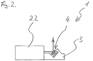
- Fig. 2 shows a further embodiment of the laser processing apparatus 1.
- the deflector 4 is not spatially separated from the laser beam source 22 but the mounting plate 3 of the deflector 4 is attached to the laser beam source 22, for example screwed or glued.
- the coupling-out optical system can be integrated in the laser beam source.
- Fig. 3 shows an enlarged sectional view of the device 4 for deflecting the laser beam 2 from Fig. 1 or 2 ,
- the device 4 has the body 3.
- a compact deflection unit 11 comprises a component 12, a flexible element 13, and two coil pairs 14 as current-carrying elements.
- the body 3 is processed, e.g. partly gilded and structured. Furthermore, so-called MEMS components (micro-electro-mechanical systems), of which parts of the device 4 optionally consist, are manufactured separately. This is a hybrid construction consisting of both parts made with MEMS techniques and "traditionally” made parts, ie parts made by machining or non-cutting.
- MEMS components micro-electro-mechanical systems
- the so-called MEMS components essentially comprise the component 12, which comprises a reflecting surface 15 and a connecting element 16, and the flexible element 13.
- the component 12 consists of quartz glass at least in the region of the reflecting surface 15 and has a dielectric coating.
- the region of the reflecting surface 15 can also be made of silicon, ceramic or metal and / or have a metallic coating.
- the dielectric / metallic coating is provided on the specular surface 15, but may alternatively also be present on the opposite side.
- a chamber 18 is formed in the body 3.
- the chamber 18 receives the current-carrying elements 14, the flexible element 13 and the connecting element 16 with a magnet as a first force-applying component 17.
- a chamber 18 must be formed, but it can only be provided a space in which the elements can be arranged.
- the reflecting surface 15 must be as large as possible, so that the largest possible laser spot can be deflected, in order then to be able to produce a small laser spot on the workpiece.
- reinforced drive elements, ie the current-carrying elements 14 and / or the magnet are required.
- the width and length of the square reflective surface 15 of the device 12 are here 7.5 mm x 7.5 mm. Alternatively, they are at least 2 mm x 2 mm but less than 15 mm x 15 mm, and preferably less than 10 mm x 10 mm.
- the laser spot on the specular surface 15 is not circular but substantially elliptical. Therefore, to make the specular surface 15 as small as possible and as large as necessary, the specular surface 15 may also have an elliptical, circular, or other suitable shape and dimension. A shape and dimensions of the reflecting surface 15 then correspond to a predetermined shape and maximum dimensions of the laser spot.
- the reflective surface is flat, but may alternatively be curved.
- the component 12 is further provided with the connecting element 16.
- the connecting element 16 is arranged in a region facing away from the reflective surface 15.
- the connecting element 16 has the magnet 17 in an area opposite the reflecting surface 15, here at the end.
- the magnet 17 is alternatively not necessarily provided at the end of the connecting element 16, but may be provided at an arbitrary position of the connecting element 16 or at another suitable location on the component 12. Alternatively, it is also possible to arrange a plurality of magnets at arbitrary locations.
- the connecting element 16 is connected to the structural body 3 via the flexible element 13.
- the flexible element 13 is designed as a spring element which connects the connecting element 16 with the body 3.
- the flexible element 13 is arranged below the reflecting surface 15.
- the flexible element 13 can also be arranged laterally from the reflecting surface 15. This reduces the height of the device 4.
- the device 12 is pivotable about an arbitrary spatial axis.
- the pivoting about the arbitrary spatial axis can be understood as a pivoting about an axis or a superimposed pivoting about two axes of a spatial coordinate system, wherein none of the axes is arranged perpendicular to the reflecting surface 15. This would only lead to a rotation of the reflecting surface 15, without a deflection of the laser beam 2 is changed.
- a deflection of the component 12, and thus of the reflecting surface 15 is made possible by a deflection angle. This allows the deflection of the laser beam 2 to any Point on a surface which is limited by the pivoting range of the reflective surface 15.
- a first coil pair 14 consists of two coils, which face each other with respect to the magnet 17 in a plane. When current flows through, the first coil pair 14 thus forms a resulting magnetic field with an axis. Another coil pair 14 is rotated so that the axis of the magnetic field of the further coil pair 14 is rotated parallel to the plane in which the first coil pair 14 is arranged, rotated by 90 °, so that the coil pairs 14 are arranged perpendicular to each other twisted. Alternatively, a plurality of coil pairs 14 are possible and the coil pairs 14 need not be rotated perpendicular to each other, but may include another suitable angle to each other.
- the magnet 17 can be deflected by the magnetic fields formed by the coil pairs 14 in such a way that the component 12 can be pivoted about the deflection angle around the arbitrary spatial axis.
- the change in the optical deflection angle of the laser beam 2 is at least ⁇ 10 ° and in an alternative embodiment preferably ⁇ 20 °. This results in a deflection angle of the reflecting surface 15 of ⁇ 5 ° or preferably ⁇ 10 °.
- the coil pairs 14 are disposed below the specular surface 15, but may alternatively be disposed laterally of the specular surface 15 to reduce the height of the means 4 for deflecting the laser beam 2.
- the coil pairs 14 are driven so that the component 12 and thus the reflective surface 15 does not resonantly oscillate, so that a predetermined deflection angle is adjustable.
- a device with which a temperature gradient is actively generated below the coil pairs 14 is optionally provided.
- this device may be a Peltier element, which is mounted directly under the coil.
- a water-carrying mounting plate 9 can be used.
- a second force-applying component 14 as an alternative to the two pairs of coils 14 and parallel tracks as the current-carrying elements are possible. In these two embodiments, the deflection is magnetically induced.
- an electrical deflection across a first electrostatically chargeable member eg a cylinder charged via the flexible member 13 is used as the first force applying component 17 instead of the magnet and as the second force applying component 14 via a second electrostatically chargeable member.
- a differently charged cylinder element instead of the coil pairs also conceivable. It is essential that at least one of the first force-exerting component 17 and the second force-exerting component 14 is coupled to the component 12 and at least one of the two force-exerting components 14, 17 is adapted so that it is controllable, so that the two force-exerting components depending on the control tighten or repel.
- the device 4 is provided with an angle detection means 19.
- the change in angle is determined by the change in position of the magnet, for example by means of Hall sensors or the provision of a piezoresistive sensor.
- the device 4 for deflecting the laser beam 2 is optionally provided with a deflection angle correction control device 20.
- the deflection angle correction control device 20 controls the coil pairs 14 so that the predetermined deflection angle of the device 12 is achieved.
- Fig. 4 2 shows a schematic representation of a further embodiment of the laser processing device 1 with a rod-shaped solid medium as the active medium and with the device 4 for deflecting the laser beam 2.
- the laser processing device 1 here has the assembly body 3, on which a laser resonator 5 is arranged, and the device 4 having.
- the laser resonator 5 has as components an HR end mirror 6, a solid-state laser medium 7, a Q-switch 8 and an output mirror 9.
- a frequency conversion of the laser beam 2 is possible in order to work with other wavelengths and thus optimally process different materials.
- a pump beam source 23 which is optionally also arranged on the body 3, a pumping radiation is generated and emitted to the laser resonator 5.
- the laser processing device 1 has a lens 10 made of quartz glass.
- the lens 10 may alternatively be made of a different material or as a GRIN lens, so a gradient index lens.
- a pump beam source can be provided here, which is coupled to the laser resonator 5 by means of a fiber.
- the solid-state laser medium 7 consists of Yb: YAG, ie an ytterbium-doped yttrium-aluminum-garnet laser, or alternatively of Nd: YAG or Nd: vanadate. Alternatively, a solid-state laser medium 7 made of Yb: vanadate or another laser-active material is possible.
- the Auskoppelapt 9 is a separate optical means having a dielectric coating on the laser medium facing end face.
- the dielectric coating is partially reflective for laser light.
- the resonator optionally has a Q-switch 8 for forming an intense and very short laser pulse.
- the Q-switch 8 is here an acousto-optic modulator.
- the Q-switch 8 may be an electro-optic modulator.
- optical components ie the lens 10, the HR end mirror 6, the solid state laser medium 7, the Q-switch 8 and the output mirror 9 are fixed on the body 3 by means of soldering.
- optical components for example by gluing, laser welding, clamping or screwing with the body 3.
- the body 3 consists of a doped silicate glass (Zerodur).
- glass-ceramic e.g., ULE - Ultra Low Expansion Titanium-Silicate Glass
- ceramic e.g., alumina, aluminum nitride, or silica
- these materials have a very low coefficient of thermal expansion.
- the arrangement of the laser resonator 5 can be constructed temperature-stable. Also in this embodiment may optionally be provided for generating the temperature gradient, the above-mentioned device.
- the device 4 for deflecting the laser beam 2 is integrated in this embodiment in the body 3, on which the laser resonator 5 is constructed.
- the same thermal conditions prevail as in the laser resonator 5, as a result of which the entire laser processing apparatus 1 can be constructed in a temperature-stable manner such that an actual target position of the laser beam 2 essentially corresponds to a predetermined target position.
- the angle detection means 19 and the deflection angle correction control device 20 are provided.
- the laser processing apparatus 1 is provided with a beam shaping unit 24, which has optical components for influencing the laser beam.
- the beam shaping unit 24 is shown here in principle only and may have components that are arranged with respect to the laser beam both in front of the reflecting surface 15 and thereafter.
- the laser beam is expanded in front of the reflecting surface 15 and focused on the mirror surface 15 on the workpiece.
- optical components of the laser resonator or beam shaping unit may be configured such that astigmatism, e.g. can be corrected by a combination of cylindrical lenses.
- the laser processing device 1 may have one or more folding mirrors (deflecting mirrors), the angle of incidence on the reflecting surface 15 being in a range of 10 ° -80 °.
- the laser processing apparatus 1 with a second embodiment of the device 4 for deflecting a laser beam 2 is shown.
- the laser beam 2 is deflected (folded) by means of two deflecting mirrors 21 before the laser beam 2 strikes the specular surface 15 and is deflected from there.
- the arrangement of the elements of the device 4 is such that the MEMS components are mounted cheaper can than at the in Fig. 1 to 4 shown embodiments.
- the number of deflection mirrors 21 is alternatively not fixed to two deflection mirrors 21, but may be another suitable number.
- the deflecting mirrors can also be arranged in a plane parallel to the upper side of the structural body 3.
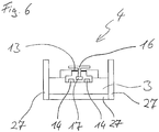
- a shield 27 is attached here.
- the shield 27 is a layer of high magnetic permeability material (iron, Mu metal (soft magnetic nickel-iron alloy), etc.).
- the shield 27 Since the magnet 17 is attracted by this layer, the shield 27 is provided at a sufficient distance and concentric with the magnet 17.
- the force acting between the magnet 17 and shield 27 should be so small that the flexible element 13, which is connected via the connecting element 16 with the magnet 17, not deformed too much.
- the distance of the shield 27 from the magnet 17 is less than 20 mm, and in a particularly preferred embodiment the distance is less than 10 mm in order to keep the device as compact as possible.
- a laser beam 2 is either generated by the laser beam source 22, or a so-called pump light is generated by the pump beam source 23, which is focused by the lens 10 in the laser resonator 5, whereby a laser beam 2 is generated.
- the laser beam 2 is deflected by the specular surface 15 of the device 12 by the predetermined deflection angle and onto a workpiece guided or focused on the workpiece.
- the predetermined deflection angle of the laser beam 2 is adjusted by adjusting the deflection angle of the device 12 by means of the control device of the laser processing device 1 by driving the current through the coil pairs 14, which deflect the device 12 by means of the magnet 17.
- the deflection of the reflecting surface 15 by means of the coil pairs 14 is then controlled so that a deflected from the reflective surface 15 of the device 12 laser beam 2, driven by the control device of the laser processing device 1, moves off a predetermined path section.
- the laser beam 2 is switched off again. This departure is either controlled from point to point or a defined trajectory is traversed.
- the workpiece may either be stationary relative to the device or may be movable relative thereto.
- the actual position detected by the angle detection means 19 is processed so that deviations between the actual position and the predetermined position, or the detected trajectory from the predetermined trajectory, are detected and corrected currents are output to the coil pairs 14 become.
- the actual position / trajectory is corrected to the predetermined position / trajectory so that there is a feedback system for accuracy of motion.
- a pre-compensation of the drive signal A can be carried out.
- the drive signal A is formed by a control voltage.
- the pre-compensation can be done according to the publication " Sub-100 ⁇ s Settling Time and Low Voltage Operation for Gimbal-less Two-Axis Scanners ", Veljko Millanovic and Kenneth Castelino, in IEEE / LEOS Optical MEMS 2004, Takamatsu, Japan, Aug. 2004 be performed.
- Fig. 7A shows a result of a step response S without the precompensation
- Fig. 7B shows a result of the step response S with the precompensation.
- the step response S is detected via a PSD signal.
- the scanner mirror can be used instead of in 700 ms without precompensation (FIG. Fig. 7A ), with a corresponding precompensation ( Fig. 7B ) are brought to a desired angle in 5 ms, ie the laser signal is directed to a desired position within the processing field.
Landscapes
- Physics & Mathematics (AREA)
- Optics & Photonics (AREA)
- Engineering & Computer Science (AREA)
- Plasma & Fusion (AREA)
- Mechanical Engineering (AREA)
- General Physics & Mathematics (AREA)
- Laser Beam Processing (AREA)
- Mechanical Optical Scanning Systems (AREA)
- Mechanical Light Control Or Optical Switches (AREA)
Description
- Die Erfindung bezieht sich auf eine Laserbearbeitungsvorrichtung zum Bearbeiten eines Werkstücks mit einer Einrichtung zum Ablenken eines Laserstrahls, insbesondere auf eine Laserbearbeitungsvorrichtung, die speziell zum Markieren eines Werkstücks verwendet wird.
- Zum Markieren von Werkstücken sind Laserbearbeitungsvorrichtungen bekannt, in denen der Laserstrahl entsprechend der gewünschten aufzubringenden Markierung mittels einer Scanneroptik abgelenkt wird und auf das Werkstück fokussiert wird.
- Die Scanneroptik weist zwei bewegliche Spiegel auf, die den Laserstrahl in zwei Richtungen ablenken. Der auf eine Oberfläche des Werkstücks auftreffende Laserstrahl markiert dann die Oberfläche. Eine Markierung, die z.B. durch eine sogenannte "Vektorbeschriftung" ausgeführt wird, besteht aus vielen aus Punkten aufgebauten Einzellinien oder beim Ausführen einer "Bitmapbeschriftung", bei der eine Fläche abgerastert wird, aus den aus einzelnen Punkten erzeugten Flächen. Dazu wird der Laserstrahl mit einer hohen Geschwindigkeit über das Werkstück geführt. Die Spiegel werden üblicherweise mittels sogenannter Galvos, nämlich Galvanometer, die jeweils einen auf einer magnetisch angetriebenen Achse vorgesehenen Spiegel aufweisen, bewegt. Durch das Anlegen einer Spannung an Spulen wird ein Magnetfeld erzeugt und die Achse, die einen Permanentmagnet aufweist, wird entsprechend der Stromstärke gegen eine Feder verdreht, wodurch der Spiegel ausgelenkt wird (moving magnet). Es gibt auch die Möglichkeit, dass der Magnet fest angebracht ist und die Spule bewegt wird (moving coil).
- Die Erfassung einer Orientierung des Spiegels, also eines Verdrehwinkels des Spiegels, kann über einen Detektor, beispielsweise einen Fotosensor, erfolgen.
- Aus dem prinzipiellen Aufbau der Galvos ergibt sich, dass für eine flächige Bearbeitung des Werkstücks mindestens zwei Galvos mit jeweils einem Spiegel erforderlich sind. Dies ist mit einem erhöhten Platzbedarf und höheren Kosten verbunden, da mehrere Bauteile erforderlich sind und der Strombedarf der Galvos hoch ist und eine entsprechende Ansteuerung erfordert.
- Ein weiterer Nachteil ist es, dass für jeden Galvo ein eigenes Positionserfassungssystem für die jeweilige Achse erforderlich ist.
- Dokument
FR 2 622 710 A1 - Im Dokument
US 4 670 638 A ist eine Vorrichtung zum Ablenken eines Laserstrahls gezeigt. Die Vorrichtung weist einen über ein Kugelgelenk gelagerten Spiegel auf. Die Vorrichtung ist mit einer Steuerung versehen, die eine Auslenkung des Spiegels ansteuert und Positionen korrigiert. - Das Dokument
US 2004/061960 A1 offenbart einen unter Verwendung von MEMS (Micro-Electro-Mechanical-Systems) -Bauteilen hergestellten Scanspiegel für beispielsweise einen Barcode-Scanner oder einen Laserdrucker. Der Spiegel ist innerhalb eines Rahmens mit verdrehbaren Stegen gehalten aus einem Stück gebildet, wodurch er, durch einen Magneten angesteuert, um eine Achse auslenkbar schwenkbar ist. - Es ist Aufgabe der Erfindung, die obigen Nachteile auszuräumen und eine Laserbearbeitungsvorrichtung mit einer Einrichtung zum Ablenken eines eine Fläche überstreichenden Laserstrahls bereitzustellen, die einen geringen Platzbedarf hat und die kostengünstig hergestellt und betrieben werden kann.
- Die Aufgabe wird durch eine Laserbearbeitungsvorrichtung gemäß Anspruch 1 gelöst. Weiterentwicklungen der Erfindung sind Gegenstand der Unteransprüche.
- Durch die Ausbildung der Laserbearbeitungsvorrichtung gemäß einem Aspekt der Erfindung kann eine Ablenkeinheit aus einem Aufbaukörper, einem Bauelement, das eine spiegelnde Oberfläche und eine erste kraftausübende Komponente aufweist, und aus mindestens einer zweiten kraftausübenden Komponente, die mit der ersten kraftausübenden Komponente zusammenwirkt, so dass das Bauelement um eine beliebige Raumachse auslenkbar ist, kompakt und kostengünstig aufgebaut werden. Dabei ist die spiegelnde Fläche so auslenkbar, dass ein durch die spiegelnde Fläche abgelenkter Laserstrahl eine Fläche überstreichen kann. Dadurch ist es möglich, ein zu der Einrichtung ortsfestes Werkstück zweidimensional zu markieren. Durch die geringen bewegten Massen ist für einen Betrieb nur ein geringer Strom erforderlich.
- Die Erfindung wird mittels Ausführungsformen an Hand der beigefügten Zeichnungen erklärt.
- Fig. 1
- zeigt eine Prinzipdarstellung einer Laserbearbeitungsvorrichtung mit einer ersten Ausführungsform einer Einrichtung zum Ablenken des Laserstrahls;
- Fig. 2
- zeigt eine Prinzipdarstellung einer weiteren Ausführungsform der Laserbearbeitungsvorrichtung mit der Einrichtung zum Ablenken des Laserstrahls;
- Fig. 3
- zeigt eine vergrößerte Schnittansicht der Einrichtung zum Ablenken eines Laserstrahls aus
Fig. 1 oder2 ; - Fig. 4
- zeigt eine Prinzipdarstellung einer weiteren Ausführungsform der Laserbearbeitungsvorrichtung, bei der ein Laserresonator und die Einrichtung zum Ablenken des Laserstrahls auf einer gemeinsamen Aufbauplatte angeordnet sind;
- Fig. 5
- zeigt eine Prinzipdarstellung noch einer weiteren Ausführungsform der Laserbearbeitungsvorrichtung mit einer zweiten Ausführungsform der Einrichtung zum Ablenken des Laserstrahls;
- Fig. 6
- zeigt eine schematische Darstellung eines Bereichs einer dritten Ausführungsform der Einrichtung zum Ablenken des Laserstrahls;
- Fig. 7A
- zeigt ein Ergebnis einer Schrittantwort eines Scanners auf ein Ansteuersignal ohne eine Vorkompensation; und
- Fig. 7B
- zeigt ein Ergebnis der Schrittantwort des Scanners auf ein Ansteuersignal mit der Vorkompensation.
-
Fig. 1 zeigt eine Prinzipdarstellung einer Laserbearbeitungsvorrichtung 1 mit einer Laserstrahlquelle 22 und mit einer ersten Ausführungsform einer Einrichtung 4 zum Ablenken eines Laserstrahls 2. Die Laserstrahlquelle 22 ist hier ein Festkörperlaser in Form eines Faserlasers, kann alternativ aber auch z.B. ein Scheiben- oder Stablaser sein. In einer weiteren alternativen Ausführungsform ist die Laserstrahlquelle 22 als ein Gaslaser ausgebildet. - Die Laserbearbeitungsvorrichtung 1 in
Fig. 1 weist eine Transportfaser 25 auf, die den Laserstrahl 2 über eine Auskoppeloptik auf die Ablenkeinrichtung 4 lenkt. Die Ablenkeinrichtung 4 und eine Auskoppeloptik 26, z.B. eine Kollimationsoptik, sind auf einer gemeinsamen Aufbauplatte 3 angeordnet. Alternativ kann die Auskoppeloptik 26 auch auf einer separaten Aufbauplatte angeordnet sein. - In
Fig. 1 ist die Transportfaser 25 für einen Laserlichttransport gezeigt. Alternativ kann auch eine Freistrahlkopplung zwischen der Laserstrahlquelle 22 und der Ablenkeinrichtung 4 vorhanden sein. -
Fig. 2 zeigt eine weitere Ausführungsform der Laserbearbeitungsvorrichtung 1. Hier ist im Unterschied zu der Laserbearbeitungsvorrichtung 1 inFig. 1 die Ablenkeinrichtung 4 nicht räumlich von der Laserstrahlquelle 22 separiert sondern die Aufbauplatte 3 der Ablenkeinrichtung 4 ist an der Laserstrahlquelle 22 angebracht, z.B. angeschraubt oder geklebt. Die Auskoppeloptik kann hierbei in der Laserstrahlquelle integriert sein. -
Fig. 3 zeigt eine vergrößerte Schnittansicht der Einrichtung 4 zum Ablenken des Laserstrahls 2 ausFig. 1 oder2 . Die Einrichtung 4 weist den Aufbaukörper 3 auf. Eine kompakte Ablenkeinheit 11 enthält ein Bauelement 12, ein flexibles Element 13, und zwei Spulenpaare 14 als stromdurchflossene Elemente. - Der Aufbaukörper 3 wird bearbeitet, z.B. teilweise vergoldet und strukturiert. Des Weiteren werden sogenannte MEMS-Bauteile (Micro-Electro-Mechanical-Systems), aus denen Teile der Einrichtung 4 optional bestehen, separat hergestellt. Es handelt sich hierbei um einen Hybridaufbau, der sowohl aus Teilen, die mit MEMS-Techniken hergestellt sind, als auch aus "traditionell" hergestellten Teilen, also mittels spanender oder spanloser Formgebung hergestellten Teilen, besteht.
- Die sogenannten MEMS-Bauteile umfassen im Wesentlichen das Bauelement 12, das eine spiegelnde Oberfläche 15 und ein Verbindungselement 16 umfasst, und das flexible Element 13. Das Bauelement 12 besteht zumindest im Bereich der spiegelnden Oberfläche 15 aus Quarzglas und weist eine dielektrische Beschichtung auf. Alternativ kann der Bereich der spiegelnden Oberfläche 15 auch aus Silizium, Keramik oder Metall bestehen und/oder eine metallische Beschichtung aufweisen. Die dielektrische/metallische Beschichtung ist auf der spiegelnden Oberfläche 15 vorgesehen, kann aber alternativ auch noch zusätzlich auf der gegenüberliegenden Seite vorhanden sein.
- Durch den Herstellungsprozess wird in dem Aufbaukörper 3 eine Kammer 18 gebildet. Die Kammer 18 nimmt die stromdurchflossenen Elemente 14, das flexible Element 13 und das Verbindungselement 16 mit einem Magnet als eine erste kraftausübende Komponente 17 auf. Alternativ muss nicht zwingend eine Kammer 18 gebildet sein, sondern es kann lediglich ein Bauraum vorgesehen sein, in dem die Elemente angeordnet sein können.
- Die spiegelnde Oberfläche 15 muss möglichst groß sein, so dass ein möglichst großer Laserspot umgelenkt werden kann, um dann einen kleinen Laserspot auf dem Werkstück erzeugen zu können. Je größer die spiegelnde Oberfläche 15 ist, umso größer ist jedoch auch die träge Masse des Bauelements 12, wodurch größere Bewegungskräfte erforderlich werden. Dadurch werden verstärkte Antriebselemente, also die stromdurchflossenen Elemente 14 und/oder der Magnet erforderlich. Die Breite und Länge der quadratischen spiegelnden Oberfläche 15 des Bauelements 12 betragen hier 7,5 mm x 7,5 mm. Alternativ betragen sie mindestens 2 mm x 2 mm aber weniger als 15 mm x 15 mm, und bevorzugt weniger als 10 mm x 10 mm. Da der Laserstrahl 2 unter einem Winkel auftrifft, der keinen senkrechten Einfall ergibt, ergibt sich der Laserspot auf der spiegelnden Oberfläche 15 nicht kreisrund sondern im Wesentlichen elliptisch. Um die spiegelnde Oberfläche 15 so klein wie möglich und so groß wie nötigt zu gestalten, kann deshalb die spiegelnde Oberfläche 15 auch eine elliptische, kreisförmige oder eine andere geeignete Form und eine andere Abmessung aufweisen. Eine Form und Abmessungen der spiegelnden Oberfläche 15 entsprechen dann einer vorbestimmten Form und maximalen Abmessungen des Laserspots. Die spiegelnde Oberfläche ist eben, kann aber alternativ auch gekrümmt ausgebildet sein.
- Das Bauelement 12 ist des Weiteren mit dem Verbindungselement 16 versehen. Das Verbindungselement 16 ist in einem der spiegelnden Fläche 15 abgewandten Bereich angeordnet. Das Verbindungselement 16 weist in einem der spiegelnden Fläche 15 gegenüberliegenden Bereich, hier am Ende, den Magnet 17 auf. Der Magnet 17 ist aber alternativ nicht zwingend am Ende des Verbindungselements 16 vorgesehen, sondern kann an einer beliebigen Stelle des Verbindungselements 16 oder an einer anderen geeigneten Stelle an dem Bauelement 12 vorgesehen sein. Alternativ können auch mehrere Magnete an beliebigen Stellen angeordnet werden.
- Das Verbindungselement 16 ist über das flexible Element 13 mit dem Aufbaukörper 3 verbunden. Das flexible Element 13 ist als ein Federelement ausgeführt, das das Verbindungselement 16 mit dem Aufbaukörper 3 verbindet. Das flexible Element 13 ist unterhalb der spiegelnden Oberfläche 15 angeordnet. Das flexible Element 13 kann weiterhin alternativ zu der Anordnung unterhalb der spiegelnden Oberfläche 15 auch seitlich von der spiegelnden Oberfläche 15 angeordnet sein. Dadurch verringert sich die Höhe der Einrichtung 4. Durch das Vorsehen des flexiblen Elements 13 ist das Bauelement 12 um eine beliebige Raumachse schwenkbar.
- Das Schwenken um die beliebige Raumachse herum kann als ein Schwenken um eine Achse oder ein überlagertes Schwenken um zwei Achsen eines Raumkoordinatensystems verstanden werden, wobei keine der Achsen senkrecht auf der spiegelnden Oberfläche 15 angeordnet ist. Dies würde lediglich zu einer Drehung der spiegelnden Oberfläche 15 führen, ohne dass eine Ablenkung des Laserstrahls 2 geändert wird. Durch das Schwenken um die beliebige Raumachse wird ein Auslenken des Bauelements 12, und damit der spiegelnden Oberfläche 15, um einen Auslenkwinkel ermöglicht. Dies ermöglicht die Ablenkung des Laserstrahls 2 auf einen beliebigen Punkt auf einer Fläche, die durch den Schwenkbereich der spiegelnden Oberfläche 15 begrenzt ist.
- Ein erstes Spulenpaar 14 besteht aus zwei Spulen, die sich bezüglich des Magneten 17 in einer Ebene gegenüberliegen. Wenn es mit Strom durchflossen ist, bildet das erste Spulenpaar 14 somit ein resultierendes Magnetfeld mit einer Achse. Ein weiteres Spulenpaar 14 ist so gedreht, dass die Achse des Magnetfelds des weiteren Spulenpaars 14 parallel zu der Ebene, in der das erste Spulenpaar 14 angeordnet ist, um 90° verdreht ist, so dass die Spulenpaare 14 senkrecht zueinander verdreht angeordnet sind. Alternativ sind auch mehrere Spulenpaare 14 möglich und die Spulenpaare 14 müssen nicht senkrecht zueinander verdreht sein, sondern können einen anderen geeigneten Winkel zueinander einschließen. Wesentlich ist, dass der Magnet 17 von den durch die Spulenpaare 14 gebildeten Magnetfeldern so ausgelenkt werden kann, dass das Bauelement 12 um die beliebige Raumachse herum um den Auslenkwinkel schwenkbar ist. Die Änderung des optischen Ablenkwinkels des Laserstrahls 2 beträgt mindestens ± 10° und in einer alternativen Ausführungsform bevorzugt ± 20°. Daraus ergibt sich ein Auslenkwinkel der spiegelnden Oberfläche 15 von ±5° bzw. bevorzugt ±10°.
- Die Spulenpaare 14 sind unterhalb der spiegelnden Oberfläche 15 angeordnet, können jedoch alternativ auch seitlich von der spiegelnden Oberfläche 15 angeordnet sein, um die Höhe der Einrichtung 4 zum Umlenken des Laserstrahls 2 zu verringern.
- Die Spulenpaare 14 werden so angesteuert, dass das Bauelement 12 und somit die spiegelnde Oberfläche 15 nicht resonant schwingt, so dass ein vorbestimmter Auslenkwinkel einstellbar ist.
- In einem Fall, in dem an den Spulenpaaren 14 hohe Ströme angelegt werden, wird die Wärmeentwicklung so groß, dass es zu Fehlfunktion oder Zerstörung der Ablenkeinrichtung 4 kommen kann. Um jedoch bei Bedarf mit höheren Strömen arbeiten zu können, wird optional eine Vorrichtung, mit der aktiv ein Temperaturgradient unterhalb der Spulenpaare 14 erzeugt wird, vorgesehen. Beispielsweise kann diese Vorrichtung ein Peltierelement sein, welches direkt unter der Spule angebracht wird. Alternativ kann eine wasserdurchflossene Aufbauplatte 9 verwendet werden.
Als eine zweite kraftausübende Komponente 14 sind als Alternative zu den zwei Spulenpaaren 14 auch parallele Leiterbahnen als die stromdurchflossenen Elemente möglich. In diesen beiden Ausführungsformen wird die Ablenkung magnetisch hervorgerufen. In einer weiteren alternativen Ausführungsform ist eine elektrische Ablenkung über ein erstes elektrostatisch aufladbares Bauteil, z.B. einen über das flexible Element 13 aufgeladenen Zylinder, anstelle des Magneten als die erste kraftausübende Komponente 17, und als die zweite kraftausübende Komponente 14 über ein zweites elektrostatisch aufladbares Bauteil, z.B. ein anders geladenes Zylinderelement, anstelle der Spulenpaare auch denkbar. Wesentlich ist, dass mindestens eine von der ersten kraftausübenden Komponente 17 und der zweiten kraftausübenden Komponente 14 mit dem Bauelement 12 gekoppelt ist und mindestens eine der beiden kraftausübenden Komponenten 14, 17 so angepasst ist, dass sie ansteuerbar ist, so dass sich die beiden kraftausübenden Komponenten in Abhängigkeit von der Ansteuerung anziehen oder abstoßen. - Die Einrichtung 4 ist mit einem Winkelerfassungsmittel 19 versehen.
- Die Winkeländerung wird durch die Positionsänderung des Magneten, z.B. mittels Hallsensoren oder das Vorsehen eines piezoresistiven Sensors bestimmt. Weiterhin ist die Einrichtung 4 zum Auslenken des Laserstrahls 2 optional mit einer Auslenkwinkelkorrektursteuerungsvorrichtung 20 versehen. Die Auslenkwinkelkorrektursteuerungsvorrichtung 20 steuert die Spulenpaare 14 so an, dass der vorbestimmte Auslenkwinkel des Bauelements 12 erreicht wird.
Fig. 4 zeigt eine Prinzipdarstellung einer weiteren Ausführungsform der Laserbearbeitungsvorrichtung 1 mit einem stabförmigen Festkörpermedium als aktives Medium und mit der Einrichtung 4 zum Ablenken des Laserstrahls 2. Die Laserbearbeitungsvorrichtung 1 weist hier den Aufbaukörper 3 auf, auf dem ein Laserresonator 5 angeordnet ist, und der die Einrichtung 4 aufweist.
Der Laserresonator 5 weist als Bauteile einen HR-Endspiegel 6, ein Festkörper-Lasermedium 7, einen Güteschalter 8 und einen Auskoppelspiegel 9 auf. Optional ist eine Frequenzkonversion des Laserstrahls 2 möglich, um mit anderen Wellenlängen zu arbeiten und damit unterschiedliche Materialien optimal zu bearbeiten. - Durch eine Pumpstrahlquelle 23, die optional ebenfalls auf dem Aufbaukörper 3 angeordnet ist, wird eine Pumpstrahlung erzeugt und zu dem Laserresonator 5 abgestrahlt. Zur Fokussierung der Pumpstrahlung in den Laserresonator 5 weist die Laserbearbeitungsvorrichtung 1 eine Linse 10 aus Quarzglas auf. Die Linse 10 kann alternativ auch aus einem anderen Material oder auch als eine GRIN-Linse, also eine Gradientenindex-Linse, ausgeführt sein. Alternativ kann hier eine Pumpstrahlquelle vorgesehen sein, die mittels einer Faser mit dem Laserresonator 5 gekoppelt ist.
- Das Festkörper-Lasermedium 7 besteht aus Yb:YAG, also einem Ytterbium dotierten Yttrium-Aluminium-Granat-Laser, oder alternativ aus Nd:YAG oder Nd:Vanadat. Alternativ ist auch ein Festkörper-Lasermedium 7 aus Yb:Vanadat oder einem anderen laseraktiven Material möglich.
- Der Auskoppelspiegel 9 ist ein separates optisches Mittel, das auf der dem Lasermedium zugewandten Stirnseite eine dielektrische Beschichtung aufweist. Die dielektrische Beschichtung ist für Laserlicht teilreflektierend.
- Bei Lasern mit Pulserzeugung weist der Resonator optional einen Güteschalter 8 zur Bildung eines intensiven und sehr kurzen Laserpulses auf. Der Güteschalter 8 ist hier ein akustooptischer Modulator. Alternativ kann der Güteschalter 8 ein elektrooptischer Modulator sein. Alternativ sind auch andere Arten der Pulserzeugung und damit eine Verwendung anderer optischer Elemente, wie z.B. passive Modenkopplung mit Hilfe eines sättigbaren Absorbers im Resonator, denkbar.
- Die optischen Komponenten, also die Linse 10, der HR-Endspiegel 6, das Festkörper-Lasermedium 7, der Güteschalter 8 und der Auskoppelspiegel 9 sind auf dem Aufbaukörper 3 mittels Löten befestigt. Alternativ besteht auch die Möglichkeit, die optischen Komponenten beispielsweise mittels Kleben, Laserschweißen, Klemmen oder Anschrauben mit dem Aufbaukörper 3 zu verbinden.
- Der Aufbaukörper 3 besteht aus einem dotierten Silikatglas (Zerodur) . Alternativ ist auch Glaskeramik (z.B. ULE - Ultra Low Expansion Titanium-Silicatglas) oder Keramik (z.B. Aluminiumoxid, Aluminiumnitrid oder Siliziumoxid) möglich. Diese Materialien weisen einen sehr niedrigen thermischen Ausdehnungskoeffizienten auf. Dadurch kann die Anordnung des Laserresonators 5 temperaturstabil aufgebaut werden. Auch in dieser Ausführungsform kann optional die vorangehend erwähnte Vorrichtung zur Erzeugung des Temperaturgradienten vorgesehen sein.
- Die Einrichtung 4 zum Ablenken des Laserstrahls 2 ist in dieser Ausführungsform in dem Aufbaukörper 3, auf dem der Laserresonator 5 aufgebaut ist, integriert. Dadurch herrschen die gleichen thermischen Bedingungen wie in dem Laserresonator 5, wodurch die gesamte Laserbearbeitungsvorrichtung 1 temperaturstabil aufgebaut werden kann, so dass eine tatsächliche Zielposition des Laserstrahls 2 im Wesentlichen einer vorbestimmten Zielposition entspricht.
- Durch die Integration der Einrichtung 4 zum Ablenken des Laserstrahls 2 in den Aufbaukörper 3 ist es grundsätzlich möglich, den Aufbaukörper 3 sowohl für das Erzeugen des Laserresonators 5 als auch für das Herstellen der Einrichtung 4 in gleichen Arbeitsgängen zu bearbeiten. Handlingseinrichtungen und Greifer, die beim Positionieren der optischen Komponenten des Laserresonators 5 verwendet werden, können grundsätzlich ebenfalls für ein Zusammenfügen der MEMS- und Nicht-MEMS-Bauteile verwendet werden.
- Optional sind auch in dieser Ausführungsform die Winkelerfassungsmittel 19 und die Auslenkwinkelkorrektursteuerungsvorrichtung 20 vorgesehen.
- Als eine weitere Option ist die Laserbearbeitungsvorrichtung 1 mit einer Strahlformungseinheit 24, die optische Komponenten zur Beeinflussung des Laserstrahls aufweist, versehen. Die Strahlformungseinheit 24 ist hier nur prinzipiell dargestellt und kann Komponenten aufweisen, die bezüglich des Laserstrahls sowohl vor der spiegelnden Oberfläche 15 als auch danach angeordnet sind. Damit wird beispielsweise der Laserstrahl vor der spiegelnden Oberfläche 15 aufgeweitet und nach der spiegelnden Oberfläche 15 auf das Werkstück fokussiert.
- Des Weiteren können die optischen Komponenten des Laserresonators oder der Strahlformungseinheit derart ausgestaltet sein, dass Astigmatismus, z.B. durch eine Kombination von Zylinderlinsen, korrigiert werden kann.
- Die Laserbearbeitungsvorrichtung 1 kann einen oder mehrere Faltungsspiegel (Umlenkspiegel) aufweisen, wobei der Einfallswinkel auf die spiegelnde Oberfläche 15 in einem Bereich von 10° - 80° liegt.
- Als Beispiel ist in
Fig. 5 die Laserbearbeitungsvorrichtung 1 mit einer zweiten Ausführungsform der Einrichtung 4 zum Ablenken eines Laserstrahls 2 gezeigt. Der Unterschied zu der inFig. 4 gezeigten Ausführungsform ist, dass der Laserstrahl 2 mittels zweier Umlenkspiegel 21 umgelenkt (gefaltet) wird, bevor der Laserstrahl 2 auf die spiegelnde Oberfläche 15 trifft und von dort abgelenkt wird. Hierbei ist die Anordnung der Elemente der Einrichtung 4 so, dass die MEMS-Bauteile günstiger montiert werden können als bei den inFig. 1 bis 4 gezeigten Ausführungsformen. Die Anzahl der Umlenkspiegel 21 ist alternativ nicht auf zwei Umlenkspiegel 21 festgelegt, sondern kann eine andere geeignete Anzahl sein. Alternativ können die Umlenkspiegel auch in einer Ebene parallel zu der Oberseite des Aufbaukörpers 3 angeordnet sein. - In
Fig. 6 ist ein Bereich einer dritten Ausführungsform der Einrichtung 4 zum Ablenken des Laserstrahls schematisch gezeigt. Um die Einrichtung 4 ist hier eine Abschirmung 27 angebracht. Bei der Abschirmung 27 handelt es sich um eine Schicht eines Materials mit hoher magnetischer Permeabilität (Eisen, Mu-Metall (weichmagnetische Nickel-Eisenlegierung), etc.). Durch die Abschirmung 27 wird das durch den Magnet 17 und/oder die stromdurchflossenen Elemente 14 erzeugte Magnetfeld im Aufbaukörper 3, der aus einem nicht magnetisierbaren Material besteht, nicht durch äußere Magnetfelder beeinflusst. - Da der Magnet 17 durch diese Schicht angezogen wird, ist die Abschirmung 27 in genügendem Abstand und konzentrisch zum Magneten 17 vorgesehen. Die Kraft, die zwischen dem Magnet 17 und Abschirmung 27 wirkt, sollte so klein sein, dass sich das flexible Element 13, das über das Verbindungselement 16 mit dem Magneten 17 verbunden ist, nicht zu stark verformt. In einer bevorzugten Ausführungsform ist der Abstand der Abschirmung 27 vom Magnet 17 kleiner als 20 mm, und in einer besonders bevorzugten Ausführungsform ist der Abstand kleiner als 10 mm, um die Vorrichtung möglichst kompakt zu halten.
- Sämtliche vorgenannten alternativen Ausführungsformen sind im Wesentlichen kombinierbar, sofern keine technischen und/oder wirtschaftlichen Gründe dagegen sprechen.
- Im Betrieb wird entweder durch die Laserstrahlquelle 22 ein Laserstrahl 2 erzeugt, oder es wird durch die Pumpstrahlquelle 23 ein sogenanntes Pumplicht erzeugt, das durch die Linse 10 in den Laserresonator 5 fokussiert wird, wodurch ein Laserstrahl 2 erzeugt wird. Nach dem Einstellen des vorbestimmten Auslenkwinkels der spiegelnden Oberfläche 15 mittels einer nicht gezeigten Steuerungsvorrichtung der Laserbearbeitungsvorrichtung 1 und Einschalten des Laserstrahls 2 durch die Steuerungsvorrichtung der Laserbearbeitungsvorrichtung 1 wird der Laserstrahl 2 durch die spiegelnde Oberfläche 15 des Bauelements 12 um den vorbestimmten Ablenkwinkel abgelenkt und auf ein Werkstück geführt oder auf das Werkstück fokussiert. Der vorbestimmte Ablenkwinkel des Laserstrahls 2 wird durch Einstellen des Auslenkwinkels des Bauelements 12 mittels der Steuerungsvorrichtung der Laserbearbeitungsvorrichtung 1 über ein Ansteuern der Stromstärke durch die Spulenpaare 14, die das Bauelement 12 mittels des Magneten 17 auslenken, eingestellt.
- Im weiteren Verlauf der Bearbeitung wird die Auslenkung der spiegelnden Oberfläche 15 mittels der Spulenpaare 14 dann so angesteuert, dass ein von der spiegelnden Oberfläche 15 des Bauelements 12 abgelenkter Laserstrahl 2, von der Steuerungsvorrichtung der Laserbearbeitungsvorrichtung 1 angesteuert, einen vorbestimmten Bahnabschnitt abfährt. Nach dem Abfahren des vorbestimmten Bahnabschnitts wird der Laserstrahl 2 wieder ausgeschaltet. Dieses Abfahren wird entweder von Punkt zu Punkt gesteuert oder eine definierte Bahnkurve wird abgefahren. Somit kann durch eine Synchronisation eines Ein- und Ausschaltens oder einer Leistungsmodulierung des Laserstrahls 2 und der Auslenkung des Bauteils 12 auf dem Werkstück eine gewünschte Markierung aufgebracht werden. Das Werkstück kann relativ zu der Einrichtung entweder ortsfest sein oder relativ dazu bewegbar sein.
- Wenn die Auslenkwinkelkorrektursteuerungsvorrichtung 20 vorhanden ist, wird die von dem Winkelerfassungsmittel 19 erfasste tatsächliche Position so verarbeitet, dass Abweichungen zwischen der tatsächlichen Position und der vorbestimmten Position, oder der erfassten Bahnkurve von der vorbestimmten Bahnkurve, ermittelt werden, und korrigierte Ströme an die Spulenpaare 14 ausgegeben werden. Somit wird die tatsächliche Position/Bahnkurve auf die vorbestimmte Position/Bahnkurve korrigiert, so dass ein Feedbacksystem für eine Genauigkeit der Bewegung vorhanden ist.
- Um eine schnellere Schrittantwort des Scanners auf ein Ansteuersignal A zu ermöglichen, kann eine Vorkompensation des Ansteuersignals A vorgenommen werden. Das Ansteuersignal A wird durch eine Steuerspannung gebildet. Die Vorkompensation kann z.B. gemäß der Veröffentlichung "Sub-100 µs Settling Time and Low Voltage Operation for Gimbal-less Two-Axis Scanners", Veljko Millanovic and Kenneth Castelino, in IEEE/LEOS Optical MEMS 2004, Takamatsu, Japan, Aug. 2004 durchgeführt werden.
Fig. 7A zeigt ein Ergebnis einer Schrittantwort S ohne die Vorkompensation undFig. 7B zeigt ein Ergebnis der Schrittantwort S mit der Vorkompensation. Die Schrittantwort S wird über ein PSD-Signal erfasst. Wie hier zu sehen ist, kann bei einem beispielhaften 4x4 mm Spiegel, der eine Resonanzfrequenz von 164 Hz aufweist und mit 80 mA betrieben wird, der Scannerspiegel anstatt in 700 ms ohne Vorkompensation (Fig. 7A ), bei einer entsprechenden Vorkompensation (Fig. 7B ) in 5 ms in einen gewünschten Winkel gebracht werden, d.h. das Lasersignal an eine gewünschte Position innerhalb des Bearbeitungsfeldes gelenkt werden. - Eine alternative Verwendung ist auch bei einer Mikrobearbeitung oder bei einem Rapid-Prototyping denkbar.
Claims (18)
- Laserbearbeitungsvorrichtung (1) zum Bearbeiten eines Werkstücks, mit
einer Laserstrahlquelle (22) und
einer Einrichtung (4) zum Ablenken eines Laserstrahls (2) der Laserstrahlquelle (22), aufweisend:einen Aufbaukörper (3),ein Bauelement (12) mit einer spiegelnden Oberfläche (15),ein flexibles Element (13), durch das das Bauelement (12) mit dem Aufbaukörper (3) direkt verbindbar ist, wobei das Bauelement (12) um eine beliebige Raumachse um einen Auslenkwinkel auslenkbar ist,eine erste kraftausübende Komponente (17) und mindestens eine zweite kraftausübende Komponente (14), wobei zumindest eine der kraftausübenden Komponenten (14, 17) derart ansteuerbar ist, dass sich die beiden kraftausübenden Komponenten (14, 17) in Abhängigkeit von der Ansteuerung anziehen oder abstoßen,
wobei eine der kraftausübenden Komponenten (14, 17) mit dem Bauelement (12) gekoppelt ist und die beiden kraftausübenden Komponenten (14, 17) so angeordnet sind und zusammenwirken, dass das Bauelement (12) um die beliebige Raumachse um einen vorbestimmten Auslenkwinkel auslenkbar ist, dadurch gekennzeichnet, dassein Winkelerfassungsmittel (19) zum Erfassen eines tatsächlichen Auslenkwinkels, um den das Bauelement (12) ausgelenkt ist, vorgesehen ist, undeine Auslenkwinkelkorrektursteuerungsvorrichtung (20) vorgesehen ist, zum Steuern eines Auslenkens des Bauelements (12) in Abhängigkeit von dem vorbestimmten Auslenkwinkel und dem tatsächlichen Auslenkwinkel, so dass der tatsächliche Auslenkwinkel dem vorbestimmten Auslenkwinkel entspricht,wobei ein piezoresistiver Sensor als das Winkelerfassungsmittel (19) vorgesehen ist, oder
wobei die erste kraftausübende Komponente (17) mindestens ein Magnet ist, und wobei die zweite kraftausübende Komponente (14) mindestens ein stromdurchflossenes Element mit einem elektromagnetischen Kraftfeld ist, und das Winkelerfassungsmittel (19) ausgebildet ist, eine Winkeländerung durch eine Positionsänderung des mindestens einen Magneten zu bestimmen. - Laserbearbeitungsvorrichtung (1) gemäß Anspruch 1, wobei die erste kraftausübende Komponente (17) an dem Bauelement (12) in einem der spiegelnden Oberfläche (15) abgewandten Bereich angeordnet ist.
- Laserbearbeitungsvorrichtung (1) gemäß einem der vorangehenden Ansprüche, wobei die erste kraftausübende Komponente (17) an einem Verbindungselement (16) des Bauelements (12) angeordnet ist.
- Laserbearbeitungsvorrichtung (1) gemäß Anspruch 1 oder 2, wobei die erste kraftausübende Komponente (17) an dem Bauelement (12) seitlich von der spiegelnden Oberfläche angeordnet ist.
- Laserbearbeitungsvorrichtung (1) gemäß einem der vorangehenden Ansprüche, wobei die zweite kraftausübende Komponente (14) seitlich der spiegelnden Oberfläche (15) angeordnet ist.
- Laserbearbeitungsvorrichtung (1) gemäß Anspruch 1 bis 4, wobei die zweite kraftausübende Komponente (14) unterhalb der spiegelnden Oberfläche angeordnet ist.
- Laserbearbeitungsvorrichtung (1) gemäß einem der vorangehenden Ansprüche, wobei mindestens zwei stromdurchflossene Elemente vorgesehen sind, die senkrecht zueinander verdreht angeordnet sind.
- Laserbearbeitungsvorrichtung (1) gemäß einem der vorangehenden Ansprüche, wobei das flexible Element (13) unterhalb der spiegelnden Oberfläche (15) angeordnet ist.
- Laserbearbeitungsvorrichtung (1) gemäß einem Ansprüche 1 bis 7, wobei das flexible Element (13) seitlich der spiegelnden Oberfläche (15) angeordnet ist.
- Laserbearbeitungsvorrichtung (1) gemäß einem der vorangehenden Ansprüche, wobei der Auslenkwinkel der spiegelnden Oberfläche (15) mindestens ± 5°, bevorzugt mindestens ± 10° beträgt.
- Laserbearbeitungsvorrichtung (1) gemäß einem der vorangehenden Ansprüche, wobei sie ferner ein optisches Mittel zum Fokussieren des Laserstrahls (2) auf das Werkstück aufweist.
- Laserbearbeitungsvorrichtung (1) gemäß einem der vorangehenden Ansprüche, wobei der auf die spiegelnde Oberfläche (15) auftreffende Laserstrahl (2) einen Laserspot mit einer vorbestimmten Form und maximalen vorbestimmten Abmessungen bildet, und wobei die spiegelnde Oberfläche (15) eine Form und Abmessungen aufweist, die im Wesentlichen der vorbestimmten Form und den maximalen Abmessungen des Laserspots entsprechen.
- Laserbearbeitungsvorrichtung (1) gemäß einem der vorangehenden Ansprüche, wobei sie MEMS-Bauteile aufweist.
- Laserbearbeitungsvorrichtung (1) gemäß einem der vorangehenden Ansprüche, wobei sie eine Steuerungsvorrichtung zum Ansteuern eines Ein- und Ausschaltens des Laserstrahls (2) und zum Ansteuern eines Auslenkens um den vorbestimmten Auslenkwinkel aufweist, so dass ein vorbestimmter Bahnabschnitt mit dem Laserstrahl (2) auf dem Werkstück abfahrbar ist.
- Laserbearbeitungsvorrichtung (1) gemäß einem der vorangehenden Ansprüche,
wobei sie einen auf dem Aufbaukörper (3) angebrachten Laserresonator (5) aufweist. - Laserbearbeitungsvorrichtung (1) gemäß einem der vorangehenden Ansprüche, wobei die Laserbearbeitungsvorrichtung (1) eine Lasermarkierungsvorrichtung ist.
- Verfahren zum Aufbringen einer Lasermarkierung auf einem Werkstück mit einer Laserbearbeitungsvorrichtung (1) gemäß Anspruch 16, das die Schritte aufweist:Einstellen des vorbestimmten Auslenkwinkels der spiegelnden Oberfläche (15) durch Ansteuern der ersten und/oder zweiten kraftausübenden Komponente (14, 17);Einschalten eines Laserstrahls (2) mittels einer Steuerungsvorrichtung der Laserbearbeitungsvorrichtung (1);Ansteuern der ersten und/oder zweiten kraftausübenden Komponente (14, 17) so, dass der Laserstrahl (2) auf dem Werkstück einen vorbestimmten Bahnabschnitt abfährt; undAusschalten des Laserstrahls (2) mittels der Steuerungsvorrichtung der Laserbearbeitungsvorrichtung (1).
- Verfahren gemäß Anspruch 17 mit den zusätzlichen Schritten:Bestimmen des tatsächlichen Auslenkwinkels durch Bestimmen der Winkeländerung durch Bestimmen der Positionsänderung des mindestens einen Magneten; oderBestimmen des tatsächlichen Auslenkwinkels mittels eines piezoresistiven Sensors; undSteuern des Auslenkens des Bauelements (12) in Abhängigkeit von dem vorbestimmten Auslenkwinkel und dem tatsächlichen Auslenkwinkel, so dass der tatsächliche Auslenkwinkel dem vorbestimmten Auslenkwinkel entspricht.
Priority Applications (3)
| Application Number | Priority Date | Filing Date | Title |
|---|---|---|---|
| EP13762129.8A EP2895294B1 (de) | 2012-09-14 | 2013-09-13 | Laserbearbeitungsvorrichtung |
| EP18177462.1A EP3395491B1 (de) | 2012-09-14 | 2013-09-13 | Laserbearbeitungsvorrichtung |
| EP18177465.4A EP3395492A1 (de) | 2012-09-14 | 2013-09-13 | Laserbearbeitungsvorrichtung |
Applications Claiming Priority (3)
| Application Number | Priority Date | Filing Date | Title |
|---|---|---|---|
| EP12184531.7A EP2708308A1 (de) | 2012-09-14 | 2012-09-14 | Laserbearbeitungsvorrichtung |
| EP13762129.8A EP2895294B1 (de) | 2012-09-14 | 2013-09-13 | Laserbearbeitungsvorrichtung |
| PCT/EP2013/069042 WO2014041134A1 (de) | 2012-09-14 | 2013-09-13 | Laserbearbeitungsvorrichtung |
Related Child Applications (4)
| Application Number | Title | Priority Date | Filing Date |
|---|---|---|---|
| EP18177465.4A Division-Into EP3395492A1 (de) | 2012-09-14 | 2013-09-13 | Laserbearbeitungsvorrichtung |
| EP18177465.4A Division EP3395492A1 (de) | 2012-09-14 | 2013-09-13 | Laserbearbeitungsvorrichtung |
| EP18177462.1A Division-Into EP3395491B1 (de) | 2012-09-14 | 2013-09-13 | Laserbearbeitungsvorrichtung |
| EP18177462.1A Division EP3395491B1 (de) | 2012-09-14 | 2013-09-13 | Laserbearbeitungsvorrichtung |
Publications (2)
| Publication Number | Publication Date |
|---|---|
| EP2895294A1 EP2895294A1 (de) | 2015-07-22 |
| EP2895294B1 true EP2895294B1 (de) | 2018-11-28 |
Family
ID=47088659
Family Applications (4)
| Application Number | Title | Priority Date | Filing Date |
|---|---|---|---|
| EP12184531.7A Withdrawn EP2708308A1 (de) | 2012-09-14 | 2012-09-14 | Laserbearbeitungsvorrichtung |
| EP18177465.4A Withdrawn EP3395492A1 (de) | 2012-09-14 | 2013-09-13 | Laserbearbeitungsvorrichtung |
| EP13762129.8A Active EP2895294B1 (de) | 2012-09-14 | 2013-09-13 | Laserbearbeitungsvorrichtung |
| EP18177462.1A Active EP3395491B1 (de) | 2012-09-14 | 2013-09-13 | Laserbearbeitungsvorrichtung |
Family Applications Before (2)
| Application Number | Title | Priority Date | Filing Date |
|---|---|---|---|
| EP12184531.7A Withdrawn EP2708308A1 (de) | 2012-09-14 | 2012-09-14 | Laserbearbeitungsvorrichtung |
| EP18177465.4A Withdrawn EP3395492A1 (de) | 2012-09-14 | 2013-09-13 | Laserbearbeitungsvorrichtung |
Family Applications After (1)
| Application Number | Title | Priority Date | Filing Date |
|---|---|---|---|
| EP18177462.1A Active EP3395491B1 (de) | 2012-09-14 | 2013-09-13 | Laserbearbeitungsvorrichtung |
Country Status (6)
| Country | Link |
|---|---|
| US (1) | US10386631B2 (de) |
| EP (4) | EP2708308A1 (de) |
| JP (1) | JP6505014B2 (de) |
| KR (1) | KR102140355B1 (de) |
| CN (1) | CN104812520A (de) |
| WO (1) | WO2014041134A1 (de) |
Families Citing this family (9)
| Publication number | Priority date | Publication date | Assignee | Title |
|---|---|---|---|---|
| EP3115826A1 (de) * | 2015-07-06 | 2017-01-11 | Trumpf Laser Marking Systems AG | Vorrichtung zur ablenkung eines laserstrahls |
| EP3192770B1 (de) | 2016-01-12 | 2019-07-17 | TRUMPF Schweiz AG | Vorrichtung zur zweidimensionalen ablenkung eines laserstrahls |
| EP3367315A1 (de) * | 2017-02-28 | 2018-08-29 | TRUMPF Werkzeugmaschinen GmbH + Co. KG | Produktionssystem und verfahren zum bedrucken und transportieren von werkstücken mittels eines unbemannten fluggeräts |
| CN109470453B (zh) * | 2018-11-22 | 2024-03-01 | 四川网动光电子技术有限公司 | 一种发生90度光偏转的光连接器元件检测装置 |
| DE102019115554A1 (de) * | 2019-06-07 | 2020-12-10 | Bystronic Laser Ag | Bearbeitungsvorrichtung zur Laserbearbeitung eines Werkstücks und Verfahren zur Laserbearbeitung eines Werkstücks |
| CN112122776A (zh) * | 2020-09-23 | 2020-12-25 | 苏州科韵激光科技有限公司 | 基于高速旋转反射镜的非线性形状加工系统及方法 |
| CN112742801A (zh) * | 2020-12-30 | 2021-05-04 | 镇江长悦光电科技有限公司 | 一种高速激光清洗装置及其使用方法 |
| CN113814558B (zh) * | 2021-08-18 | 2024-11-19 | 深圳市大族数控科技股份有限公司 | 激光光束像散补偿方法、装置及存储介质 |
| CN113751432B (zh) * | 2021-09-17 | 2023-05-26 | 宁波翔明激光科技有限公司 | 一种集成镜片洁净度检测装置的激光清洗头 |
Family Cites Families (59)
| Publication number | Priority date | Publication date | Assignee | Title |
|---|---|---|---|---|
| DE2503419C2 (de) * | 1975-01-28 | 1983-05-11 | Kurt 8000 München Kellner | Einrichtung zur Augenabstandseinstellung bei binokularen optischen Geräten, insbesondere zur Rückvergrößerung von Mikrofilmen |
| JPS5593544A (en) * | 1979-01-09 | 1980-07-16 | Sony Corp | Multi-axis movable mirror unit |
| US4502752A (en) * | 1982-11-08 | 1985-03-05 | General Scanning, Inc. | Resonant actuator for optical scanning |
| FR2577052B1 (fr) * | 1985-02-05 | 1988-09-09 | Bertin & Cie | Procede et dispositif de deplacement du point d'impact d'un faisceau laser sur une piece |
| DE3613233A1 (de) * | 1986-04-18 | 1987-10-22 | Rodenstock Instr Gmbh | Einrichtung zum verstellen eines lichtstrahls in einer auftreffebene |
| US4911711A (en) * | 1986-12-05 | 1990-03-27 | Taunton Technologies, Inc. | Sculpture apparatus for correcting curvature of the cornea |
| JPS63311321A (ja) * | 1987-06-15 | 1988-12-20 | Sharp Corp | 走査型光プリンタ |
| FR2622710A1 (fr) * | 1987-10-30 | 1989-05-05 | Sciaky Sa | Dispositif de commande en pivotement d'un outil et, notamment d'un miroir de reflexion d'un faisceau laser |
| US4887197A (en) * | 1988-04-29 | 1989-12-12 | O'ryan Industries | Methods and apparatus for generating light patterns responsive to audio frequency input signals |
| US5009473A (en) * | 1988-05-31 | 1991-04-23 | Reflection Technology, Inc. | Low vibration resonant scanning unit for miniature optical display apparatus |
| IL87252A (en) * | 1988-07-28 | 1992-03-29 | Israel State | Scanning device |
| US4923263A (en) * | 1988-09-22 | 1990-05-08 | The United States Of America As Represented By The Secretary Of The Army | Rotating mirror optical scanning device |
| US5870219A (en) * | 1997-01-20 | 1999-02-09 | Geo. Labs, Inc. | Ultra compact scanning system for a wide range of speeds, angles and field depth |
| US5280377A (en) * | 1991-06-28 | 1994-01-18 | Eastman Kodak Company | Beam scanning galvanometer with spring supported mirror |
| US5280491A (en) * | 1991-08-02 | 1994-01-18 | Lai Shui T | Two dimensional scan amplifier laser |
| JP2950011B2 (ja) * | 1992-04-06 | 1999-09-20 | 松下電器産業株式会社 | ミラー駆動装置 |
| JPH05334703A (ja) * | 1992-05-29 | 1993-12-17 | Matsushita Electric Ind Co Ltd | ミラー移動量検出装置 |
| JP3060813B2 (ja) * | 1993-12-28 | 2000-07-10 | トヨタ自動車株式会社 | レーザ加工装置 |
| DE59402170D1 (de) * | 1994-08-24 | 1997-04-24 | Schablonentechnik Kufstein Ag | Vorrichtung zur Herstellung einer Druckschablone |
| US5867512A (en) * | 1997-02-10 | 1999-02-02 | Sacher; Joachim | Tuning arrangement for a semiconductor diode laser with an external resonator |
| JP3259014B2 (ja) * | 1996-07-24 | 2002-02-18 | ミヤチテクノス株式会社 | スキャニング式レーザマーキング方法及び装置 |
| GB2325416B (en) * | 1997-05-23 | 2001-04-25 | Dan Hardiman | An apparatus for and method of generating light patterns in response to an electrical oscillating signal |
| JP3552601B2 (ja) * | 1998-11-16 | 2004-08-11 | 日本ビクター株式会社 | 光偏向子及びこれを用いた表示装置 |
| US6692959B2 (en) * | 1998-11-25 | 2004-02-17 | Isis Pharmaceuticals, Inc. | Antisense modulation of IL-1 receptor-associated kinase-4 expression |
| JP3065611B1 (ja) * | 1999-05-28 | 2000-07-17 | 三菱電機株式会社 | マイクロミラ―装置およびその製造方法 |
| US6304359B1 (en) * | 1999-07-20 | 2001-10-16 | Lasesys Corporation | High scan efficiency galvanometric laser scanning device |
| US6256131B1 (en) * | 1999-08-05 | 2001-07-03 | Microvision Inc. | Active tuning of a torsional resonant structure |
| JP3797922B2 (ja) * | 2001-11-27 | 2006-07-19 | オリンパス株式会社 | 光偏向装置 |
| JP3846359B2 (ja) * | 2002-05-09 | 2006-11-15 | 株式会社デンソー | 光デバイス |
| US6758571B2 (en) * | 2002-09-30 | 2004-07-06 | Texas Instruments Incorporated | Scanning MEMS mirror with reluctance force motor |
| US7149020B2 (en) * | 2002-10-07 | 2006-12-12 | Laserrave Llc | Mirror and coil laser beam projection apparatus |
| US20040184124A1 (en) * | 2002-11-13 | 2004-09-23 | Olympus Corporation | Optical deflection device |
| US7019877B2 (en) * | 2003-03-25 | 2006-03-28 | Shpizel Matvey B | Light beam deflector |
| JP2004301888A (ja) * | 2003-03-28 | 2004-10-28 | Matsushita Electric Ind Co Ltd | 光ビームスキャニング装置 |
| US7102805B2 (en) * | 2003-08-08 | 2006-09-05 | Seiko Epson Corporation | Scanner having scan angle multiplier |
| US7034415B2 (en) * | 2003-10-09 | 2006-04-25 | Texas Instruments Incorporated | Pivoting mirror with improved magnetic drive |
| US7529011B2 (en) * | 2004-04-12 | 2009-05-05 | Ricoh Company, Ltd. | Deflector mirror with regions of different flexural rigidity |
| JP4464186B2 (ja) * | 2004-04-20 | 2010-05-19 | 富士通株式会社 | マイクロ揺動素子 |
| JP4442505B2 (ja) * | 2004-07-30 | 2010-03-31 | ソニー株式会社 | 変形可能ミラー装置、変形ミラー板 |
| US7497578B2 (en) * | 2005-04-28 | 2009-03-03 | Symbol Technologies, Inc. | Monitoring scan mirror motion in electro-optical readers and image projectors |
| US7388699B1 (en) * | 2005-07-11 | 2008-06-17 | Coffee Curtis L | Musical laser display device |
| CA2631009C (en) * | 2005-12-26 | 2011-09-20 | Nippon Telegraph And Telephone Corporation | Spring, mirror element, mirror array and optical switch |
| US8319145B2 (en) * | 2006-07-10 | 2012-11-27 | Lazare Kaplan International, Inc. | System and method for gemstone micro-inscription |
| WO2008042552A2 (en) * | 2006-09-29 | 2008-04-10 | Inphase Technologies, Inc. | Magnetic field position feedback for holographic storage scanner |
| US20090323739A1 (en) * | 2006-12-22 | 2009-12-31 | Uv Tech Systems | Laser optical system |
| CN101269441A (zh) * | 2007-03-23 | 2008-09-24 | 中国科学院力学研究所 | 激光柔性加工系统 |
| KR20090051859A (ko) * | 2007-11-20 | 2009-05-25 | 삼성전기주식회사 | 스캐너 및 이를 구비하는 디스플레이 장치 |
| US7605966B2 (en) * | 2008-01-21 | 2009-10-20 | Stanley Electric Co., Ltd. | Optical deflector |
| JP2009204916A (ja) * | 2008-02-28 | 2009-09-10 | Canon Inc | 2軸駆動装置及び光偏向装置 |
| JP4823265B2 (ja) * | 2008-03-31 | 2011-11-24 | 日本電信電話株式会社 | 光スイッチ |
| KR101769157B1 (ko) * | 2008-10-20 | 2017-08-17 | 칼 짜이스 에스엠테 게엠베하 | 방사선 빔 안내를 위한 광학 모듈 |
| JP2010139991A (ja) * | 2008-12-15 | 2010-06-24 | Olympus Corp | 光スイッチ |
| JP2010256862A (ja) * | 2009-04-01 | 2010-11-11 | Seiko Epson Corp | ミラーデバイス駆動制御装置およびプロジェクター |
| JP5465495B2 (ja) * | 2009-09-07 | 2014-04-09 | 株式会社キーエンス | レーザ加工装置 |
| DE102010004084B4 (de) * | 2010-01-06 | 2023-08-03 | Gunnar Held | Laserbearbeitungsvorrichtung für groß dimensionierte Bauteile |
| CN101774083A (zh) * | 2010-02-08 | 2010-07-14 | 重庆斯沃德光电设备设计制造有限公司 | 多功能激光数控加工系统 |
| JP5811605B2 (ja) * | 2011-06-08 | 2015-11-11 | セイコーエプソン株式会社 | 表示装置 |
| CN103582840A (zh) * | 2011-07-06 | 2014-02-12 | 日本电气株式会社 | 光学扫描装置、图像显示设备和光学扫描方法 |
| US8711458B2 (en) * | 2012-05-08 | 2014-04-29 | Microvision, Inc. | Scanned image projection system employing intermediate image plane |
-
2012
- 2012-09-14 EP EP12184531.7A patent/EP2708308A1/de not_active Withdrawn
-
2013
- 2013-09-13 WO PCT/EP2013/069042 patent/WO2014041134A1/de not_active Ceased
- 2013-09-13 EP EP18177465.4A patent/EP3395492A1/de not_active Withdrawn
- 2013-09-13 EP EP13762129.8A patent/EP2895294B1/de active Active
- 2013-09-13 KR KR1020157009245A patent/KR102140355B1/ko not_active Expired - Fee Related
- 2013-09-13 EP EP18177462.1A patent/EP3395491B1/de active Active
- 2013-09-13 CN CN201380053350.8A patent/CN104812520A/zh active Pending
- 2013-09-13 JP JP2015531578A patent/JP6505014B2/ja not_active Expired - Fee Related
-
2015
- 2015-03-13 US US14/657,256 patent/US10386631B2/en active Active
Non-Patent Citations (1)
| Title |
|---|
| None * |
Also Published As
| Publication number | Publication date |
|---|---|
| JP6505014B2 (ja) | 2019-04-24 |
| EP2708308A1 (de) | 2014-03-19 |
| EP3395491A1 (de) | 2018-10-31 |
| CN104812520A (zh) | 2015-07-29 |
| US10386631B2 (en) | 2019-08-20 |
| KR20150067192A (ko) | 2015-06-17 |
| EP3395492A1 (de) | 2018-10-31 |
| JP2015533652A (ja) | 2015-11-26 |
| EP2895294A1 (de) | 2015-07-22 |
| KR102140355B1 (ko) | 2020-08-03 |
| US20150185472A1 (en) | 2015-07-02 |
| EP3395491B1 (de) | 2020-11-04 |
| WO2014041134A1 (de) | 2014-03-20 |
Similar Documents
| Publication | Publication Date | Title |
|---|---|---|
| EP3395491B1 (de) | Laserbearbeitungsvorrichtung | |
| WO2014041129A1 (de) | Einrichtung zum ablenken eines laserstrahls | |
| DE102013223933B4 (de) | Resonanz-Mikrospiegelanordnung | |
| DE102019115554A1 (de) | Bearbeitungsvorrichtung zur Laserbearbeitung eines Werkstücks und Verfahren zur Laserbearbeitung eines Werkstücks | |
| EP3932609B1 (de) | Vorrichtung zur lasermaterialbearbeitung mit zwei parallel-versatz-einheiten des laserstrahles | |
| EP2073047A1 (de) | Verfahren zur Montage und Justage einer elektro-optischen Vorrichtung sowie Messgerät montiert und justiert nach einem derartigen Verfahren | |
| DE10053402B4 (de) | Verfahren und Vorrichtung zum thermischen Fügen von Bauteilen aus silikatischen Werkstoffen, Silikat-Verbundwerkstoffen und Silikat-Kompositwerkstoffen | |
| EP3602105B1 (de) | Winkelmagnetfeldsensor für scanner | |
| EP1186927B1 (de) | Verstellvorrichtung und Verfahren zu ihrer Justierung | |
| EP2591390A1 (de) | Optische scan-einrichtung | |
| EP3747588A1 (de) | Bearbeitungsvorrichtung zur laserbearbeitung eines werkstücks und verfahren zur laserbearbeitung eines werkstücks | |
| EP1738215A1 (de) | Bestimmung der auslenkung von mikrospiegeln in einem projektionssystem | |
| DE102019128251A1 (de) | Verfahren zum Fügen von zwei Fügepartnern mittels ultrakurzer Laserpulse | |
| DE102016111531B4 (de) | Optischer Scanner | |
| EP3576898B1 (de) | Verfahren zum fügen von bauteilen auf eine trägerstruktur unter einsatz von elektromagnetischer strahlung | |
| DE102016208131B4 (de) | Verfahren und Vorrichtung zum Bearbeiten eines Werkstücks | |
| DE102015103164B4 (de) | Scanvorrichtung mit wenigstens einer eindimensional scannenden Scaneinheit | |
| EP1395859B1 (de) | Laserjustierbarer Aktor, optisches Bauelement und Justierverfahren | |
| DE102021126360B4 (de) | Verfahren zur Bearbeitung eines Werkstücks durch Laserstrahlung in Form von Lissajous-Figuren | |
| DE102021128848A1 (de) | Vorrichtung zum desorbierenden Abtasten von Analytmaterial auf einem Probenträger | |
| EP1717631B1 (de) | Mikrooptische Anordnung | |
| DE102024101592A1 (de) | Optische Anordnung und Verfahren zum Versetzen eines mit einer Fassung gefassten optischen Bauteils in eine periodische lineare Schwingung | |
| DE102014207899A1 (de) | 3D Fein-Laserscanner | |
| DE102021105559A1 (de) | Spiegelvorrichtung für ein Fertigungssystem zur laserstrahlbasierten Fertigung, Fertigungssystem und Verfahren | |
| DE19947022A1 (de) | Verfahren zur Linsenjustage eines optischen Empfängerbauelements |
Legal Events
| Date | Code | Title | Description |
|---|---|---|---|
| PUAI | Public reference made under article 153(3) epc to a published international application that has entered the european phase |
Free format text: ORIGINAL CODE: 0009012 |
|
| 17P | Request for examination filed |
Effective date: 20150407 |
|
| AK | Designated contracting states |
Kind code of ref document: A1 Designated state(s): AL AT BE BG CH CY CZ DE DK EE ES FI FR GB GR HR HU IE IS IT LI LT LU LV MC MK MT NL NO PL PT RO RS SE SI SK SM TR |
|
| AX | Request for extension of the european patent |
Extension state: BA ME |
|
| DAX | Request for extension of the european patent (deleted) | ||
| 17Q | First examination report despatched |
Effective date: 20160519 |
|
| STAA | Information on the status of an ep patent application or granted ep patent |
Free format text: STATUS: EXAMINATION IS IN PROGRESS |
|
| RAP1 | Party data changed (applicant data changed or rights of an application transferred) |
Owner name: TRUMPF SCHWEIZ AG |
|
| GRAP | Despatch of communication of intention to grant a patent |
Free format text: ORIGINAL CODE: EPIDOSNIGR1 |
|
| STAA | Information on the status of an ep patent application or granted ep patent |
Free format text: STATUS: GRANT OF PATENT IS INTENDED |
|
| INTG | Intention to grant announced |
Effective date: 20180502 |
|
| GRAJ | Information related to disapproval of communication of intention to grant by the applicant or resumption of examination proceedings by the epo deleted |
Free format text: ORIGINAL CODE: EPIDOSDIGR1 |
|
| STAA | Information on the status of an ep patent application or granted ep patent |
Free format text: STATUS: EXAMINATION IS IN PROGRESS |
|
| GRAJ | Information related to disapproval of communication of intention to grant by the applicant or resumption of examination proceedings by the epo deleted |
Free format text: ORIGINAL CODE: EPIDOSDIGR1 |
|
| STAA | Information on the status of an ep patent application or granted ep patent |
Free format text: STATUS: GRANT OF PATENT IS INTENDED |
|
| GRAP | Despatch of communication of intention to grant a patent |
Free format text: ORIGINAL CODE: EPIDOSNIGR1 |
|
| INTG | Intention to grant announced |
Effective date: 20180914 |
|
| GRAS | Grant fee paid |
Free format text: ORIGINAL CODE: EPIDOSNIGR3 |
|
| GRAA | (expected) grant |
Free format text: ORIGINAL CODE: 0009210 |
|
| STAA | Information on the status of an ep patent application or granted ep patent |
Free format text: STATUS: THE PATENT HAS BEEN GRANTED |
|
| AK | Designated contracting states |
Kind code of ref document: B1 Designated state(s): AL AT BE BG CH CY CZ DE DK EE ES FI FR GB GR HR HU IE IS IT LI LT LU LV MC MK MT NL NO PL PT RO RS SE SI SK SM TR |
|
| REG | Reference to a national code |
Ref country code: CH Ref legal event code: EP |
|
| REG | Reference to a national code |
Ref country code: DE Ref legal event code: R096 Ref document number: 502013011729 Country of ref document: DE |
|
| REG | Reference to a national code |
Ref country code: AT Ref legal event code: REF Ref document number: 1069657 Country of ref document: AT Kind code of ref document: T Effective date: 20181215 |
|
| REG | Reference to a national code |
Ref country code: IE Ref legal event code: FG4D Free format text: LANGUAGE OF EP DOCUMENT: GERMAN |
|
| REG | Reference to a national code |
Ref country code: CH Ref legal event code: NV Representative=s name: DENNEMEYER AG, CH |
|
| REG | Reference to a national code |
Ref country code: NL Ref legal event code: MP Effective date: 20181128 |
|
| REG | Reference to a national code |
Ref country code: LT Ref legal event code: MG4D |
|
| PG25 | Lapsed in a contracting state [announced via postgrant information from national office to epo] |
Ref country code: ES Free format text: LAPSE BECAUSE OF FAILURE TO SUBMIT A TRANSLATION OF THE DESCRIPTION OR TO PAY THE FEE WITHIN THE PRESCRIBED TIME-LIMIT Effective date: 20181128 Ref country code: LV Free format text: LAPSE BECAUSE OF FAILURE TO SUBMIT A TRANSLATION OF THE DESCRIPTION OR TO PAY THE FEE WITHIN THE PRESCRIBED TIME-LIMIT Effective date: 20181128 Ref country code: FI Free format text: LAPSE BECAUSE OF FAILURE TO SUBMIT A TRANSLATION OF THE DESCRIPTION OR TO PAY THE FEE WITHIN THE PRESCRIBED TIME-LIMIT Effective date: 20181128 Ref country code: BG Free format text: LAPSE BECAUSE OF FAILURE TO SUBMIT A TRANSLATION OF THE DESCRIPTION OR TO PAY THE FEE WITHIN THE PRESCRIBED TIME-LIMIT Effective date: 20190228 Ref country code: HR Free format text: LAPSE BECAUSE OF FAILURE TO SUBMIT A TRANSLATION OF THE DESCRIPTION OR TO PAY THE FEE WITHIN THE PRESCRIBED TIME-LIMIT Effective date: 20181128 Ref country code: NO Free format text: LAPSE BECAUSE OF FAILURE TO SUBMIT A TRANSLATION OF THE DESCRIPTION OR TO PAY THE FEE WITHIN THE PRESCRIBED TIME-LIMIT Effective date: 20190228 Ref country code: LT Free format text: LAPSE BECAUSE OF FAILURE TO SUBMIT A TRANSLATION OF THE DESCRIPTION OR TO PAY THE FEE WITHIN THE PRESCRIBED TIME-LIMIT Effective date: 20181128 Ref country code: IS Free format text: LAPSE BECAUSE OF FAILURE TO SUBMIT A TRANSLATION OF THE DESCRIPTION OR TO PAY THE FEE WITHIN THE PRESCRIBED TIME-LIMIT Effective date: 20190328 |
|
| PG25 | Lapsed in a contracting state [announced via postgrant information from national office to epo] |
Ref country code: RS Free format text: LAPSE BECAUSE OF FAILURE TO SUBMIT A TRANSLATION OF THE DESCRIPTION OR TO PAY THE FEE WITHIN THE PRESCRIBED TIME-LIMIT Effective date: 20181128 Ref country code: PT Free format text: LAPSE BECAUSE OF FAILURE TO SUBMIT A TRANSLATION OF THE DESCRIPTION OR TO PAY THE FEE WITHIN THE PRESCRIBED TIME-LIMIT Effective date: 20190328 Ref country code: GR Free format text: LAPSE BECAUSE OF FAILURE TO SUBMIT A TRANSLATION OF THE DESCRIPTION OR TO PAY THE FEE WITHIN THE PRESCRIBED TIME-LIMIT Effective date: 20190301 Ref country code: SE Free format text: LAPSE BECAUSE OF FAILURE TO SUBMIT A TRANSLATION OF THE DESCRIPTION OR TO PAY THE FEE WITHIN THE PRESCRIBED TIME-LIMIT Effective date: 20181128 Ref country code: AL Free format text: LAPSE BECAUSE OF FAILURE TO SUBMIT A TRANSLATION OF THE DESCRIPTION OR TO PAY THE FEE WITHIN THE PRESCRIBED TIME-LIMIT Effective date: 20181128 |
|
| PG25 | Lapsed in a contracting state [announced via postgrant information from national office to epo] |
Ref country code: NL Free format text: LAPSE BECAUSE OF FAILURE TO SUBMIT A TRANSLATION OF THE DESCRIPTION OR TO PAY THE FEE WITHIN THE PRESCRIBED TIME-LIMIT Effective date: 20181128 |
|
| PG25 | Lapsed in a contracting state [announced via postgrant information from national office to epo] |
Ref country code: CZ Free format text: LAPSE BECAUSE OF FAILURE TO SUBMIT A TRANSLATION OF THE DESCRIPTION OR TO PAY THE FEE WITHIN THE PRESCRIBED TIME-LIMIT Effective date: 20181128 Ref country code: PL Free format text: LAPSE BECAUSE OF FAILURE TO SUBMIT A TRANSLATION OF THE DESCRIPTION OR TO PAY THE FEE WITHIN THE PRESCRIBED TIME-LIMIT Effective date: 20181128 Ref country code: DK Free format text: LAPSE BECAUSE OF FAILURE TO SUBMIT A TRANSLATION OF THE DESCRIPTION OR TO PAY THE FEE WITHIN THE PRESCRIBED TIME-LIMIT Effective date: 20181128 |
|
| REG | Reference to a national code |
Ref country code: DE Ref legal event code: R097 Ref document number: 502013011729 Country of ref document: DE |
|
| PG25 | Lapsed in a contracting state [announced via postgrant information from national office to epo] |
Ref country code: RO Free format text: LAPSE BECAUSE OF FAILURE TO SUBMIT A TRANSLATION OF THE DESCRIPTION OR TO PAY THE FEE WITHIN THE PRESCRIBED TIME-LIMIT Effective date: 20181128 Ref country code: SK Free format text: LAPSE BECAUSE OF FAILURE TO SUBMIT A TRANSLATION OF THE DESCRIPTION OR TO PAY THE FEE WITHIN THE PRESCRIBED TIME-LIMIT Effective date: 20181128 Ref country code: SM Free format text: LAPSE BECAUSE OF FAILURE TO SUBMIT A TRANSLATION OF THE DESCRIPTION OR TO PAY THE FEE WITHIN THE PRESCRIBED TIME-LIMIT Effective date: 20181128 Ref country code: EE Free format text: LAPSE BECAUSE OF FAILURE TO SUBMIT A TRANSLATION OF THE DESCRIPTION OR TO PAY THE FEE WITHIN THE PRESCRIBED TIME-LIMIT Effective date: 20181128 |
|
| PLBE | No opposition filed within time limit |
Free format text: ORIGINAL CODE: 0009261 |
|
| STAA | Information on the status of an ep patent application or granted ep patent |
Free format text: STATUS: NO OPPOSITION FILED WITHIN TIME LIMIT |
|
| PG25 | Lapsed in a contracting state [announced via postgrant information from national office to epo] |
Ref country code: SI Free format text: LAPSE BECAUSE OF FAILURE TO SUBMIT A TRANSLATION OF THE DESCRIPTION OR TO PAY THE FEE WITHIN THE PRESCRIBED TIME-LIMIT Effective date: 20181128 |
|
| 26N | No opposition filed |
Effective date: 20190829 |
|
| PG25 | Lapsed in a contracting state [announced via postgrant information from national office to epo] |
Ref country code: TR Free format text: LAPSE BECAUSE OF FAILURE TO SUBMIT A TRANSLATION OF THE DESCRIPTION OR TO PAY THE FEE WITHIN THE PRESCRIBED TIME-LIMIT Effective date: 20181128 |
|
| PG25 | Lapsed in a contracting state [announced via postgrant information from national office to epo] |
Ref country code: MC Free format text: LAPSE BECAUSE OF FAILURE TO SUBMIT A TRANSLATION OF THE DESCRIPTION OR TO PAY THE FEE WITHIN THE PRESCRIBED TIME-LIMIT Effective date: 20181128 |
|
| PG25 | Lapsed in a contracting state [announced via postgrant information from national office to epo] |
Ref country code: LU Free format text: LAPSE BECAUSE OF NON-PAYMENT OF DUE FEES Effective date: 20190913 Ref country code: IE Free format text: LAPSE BECAUSE OF NON-PAYMENT OF DUE FEES Effective date: 20190913 |
|
| REG | Reference to a national code |
Ref country code: BE Ref legal event code: MM Effective date: 20190930 |
|
| PG25 | Lapsed in a contracting state [announced via postgrant information from national office to epo] |
Ref country code: BE Free format text: LAPSE BECAUSE OF NON-PAYMENT OF DUE FEES Effective date: 20190930 |
|
| REG | Reference to a national code |
Ref country code: AT Ref legal event code: MM01 Ref document number: 1069657 Country of ref document: AT Kind code of ref document: T Effective date: 20190913 |
|
| PG25 | Lapsed in a contracting state [announced via postgrant information from national office to epo] |
Ref country code: AT Free format text: LAPSE BECAUSE OF NON-PAYMENT OF DUE FEES Effective date: 20190913 |
|
| PG25 | Lapsed in a contracting state [announced via postgrant information from national office to epo] |
Ref country code: CY Free format text: LAPSE BECAUSE OF FAILURE TO SUBMIT A TRANSLATION OF THE DESCRIPTION OR TO PAY THE FEE WITHIN THE PRESCRIBED TIME-LIMIT Effective date: 20181128 |
|
| PG25 | Lapsed in a contracting state [announced via postgrant information from national office to epo] |
Ref country code: MT Free format text: LAPSE BECAUSE OF FAILURE TO SUBMIT A TRANSLATION OF THE DESCRIPTION OR TO PAY THE FEE WITHIN THE PRESCRIBED TIME-LIMIT Effective date: 20181128 Ref country code: HU Free format text: LAPSE BECAUSE OF FAILURE TO SUBMIT A TRANSLATION OF THE DESCRIPTION OR TO PAY THE FEE WITHIN THE PRESCRIBED TIME-LIMIT; INVALID AB INITIO Effective date: 20130913 |
|
| PG25 | Lapsed in a contracting state [announced via postgrant information from national office to epo] |
Ref country code: MK Free format text: LAPSE BECAUSE OF FAILURE TO SUBMIT A TRANSLATION OF THE DESCRIPTION OR TO PAY THE FEE WITHIN THE PRESCRIBED TIME-LIMIT Effective date: 20181128 |
|
| PGFP | Annual fee paid to national office [announced via postgrant information from national office to epo] |
Ref country code: GB Payment date: 20220920 Year of fee payment: 10 Ref country code: DE Payment date: 20220920 Year of fee payment: 10 |
|
| PGFP | Annual fee paid to national office [announced via postgrant information from national office to epo] |
Ref country code: FR Payment date: 20220922 Year of fee payment: 10 |
|
| PGFP | Annual fee paid to national office [announced via postgrant information from national office to epo] |
Ref country code: IT Payment date: 20220926 Year of fee payment: 10 |
|
| PGFP | Annual fee paid to national office [announced via postgrant information from national office to epo] |
Ref country code: CH Payment date: 20220928 Year of fee payment: 10 |
|
| REG | Reference to a national code |
Ref country code: DE Ref legal event code: R119 Ref document number: 502013011729 Country of ref document: DE |
|
| REG | Reference to a national code |
Ref country code: CH Ref legal event code: PL |
|
| GBPC | Gb: european patent ceased through non-payment of renewal fee |
Effective date: 20230913 |
|
| PG25 | Lapsed in a contracting state [announced via postgrant information from national office to epo] |
Ref country code: GB Free format text: LAPSE BECAUSE OF NON-PAYMENT OF DUE FEES Effective date: 20230913 |
|
| PG25 | Lapsed in a contracting state [announced via postgrant information from national office to epo] |
Ref country code: CH Free format text: LAPSE BECAUSE OF NON-PAYMENT OF DUE FEES Effective date: 20230930 |
|
| PG25 | Lapsed in a contracting state [announced via postgrant information from national office to epo] |
Ref country code: GB Free format text: LAPSE BECAUSE OF NON-PAYMENT OF DUE FEES Effective date: 20230913 Ref country code: FR Free format text: LAPSE BECAUSE OF NON-PAYMENT OF DUE FEES Effective date: 20230930 Ref country code: DE Free format text: LAPSE BECAUSE OF NON-PAYMENT OF DUE FEES Effective date: 20240403 Ref country code: CH Free format text: LAPSE BECAUSE OF NON-PAYMENT OF DUE FEES Effective date: 20230930 |
|
| PG25 | Lapsed in a contracting state [announced via postgrant information from national office to epo] |
Ref country code: IT Free format text: LAPSE BECAUSE OF NON-PAYMENT OF DUE FEES Effective date: 20230913 |
|
| PG25 | Lapsed in a contracting state [announced via postgrant information from national office to epo] |
Ref country code: IT Free format text: LAPSE BECAUSE OF NON-PAYMENT OF DUE FEES Effective date: 20230913 |