EP2894277A1 - A method for mounting facade elements on a multi-storey building - Google Patents
A method for mounting facade elements on a multi-storey building Download PDFInfo
- Publication number
- EP2894277A1 EP2894277A1 EP14198624.0A EP14198624A EP2894277A1 EP 2894277 A1 EP2894277 A1 EP 2894277A1 EP 14198624 A EP14198624 A EP 14198624A EP 2894277 A1 EP2894277 A1 EP 2894277A1
- Authority
- EP
- European Patent Office
- Prior art keywords
- facade
- facade element
- type
- vertical
- floor
- Prior art date
- Legal status (The legal status is an assumption and is not a legal conclusion. Google has not performed a legal analysis and makes no representation as to the accuracy of the status listed.)
- Granted
Links
- 238000000034 method Methods 0.000 title claims abstract description 53
- 238000007789 sealing Methods 0.000 claims description 14
- 238000003860 storage Methods 0.000 claims description 6
- 238000003780 insertion Methods 0.000 claims description 5
- 230000037431 insertion Effects 0.000 claims description 5
- FGUUSXIOTUKUDN-IBGZPJMESA-N C1(=CC=CC=C1)N1C2=C(NC([C@H](C1)NC=1OC(=NN=1)C1=CC=CC=C1)=O)C=CC=C2 Chemical compound C1(=CC=CC=C1)N1C2=C(NC([C@H](C1)NC=1OC(=NN=1)C1=CC=CC=C1)=O)C=CC=C2 FGUUSXIOTUKUDN-IBGZPJMESA-N 0.000 claims description 2
- 238000009434 installation Methods 0.000 description 12
- 239000011521 glass Substances 0.000 description 3
- 230000005540 biological transmission Effects 0.000 description 2
- 239000002783 friction material Substances 0.000 description 2
- 238000012432 intermediate storage Methods 0.000 description 2
- 230000001360 synchronised effect Effects 0.000 description 2
- 230000032258 transport Effects 0.000 description 2
- 101000840273 Homo sapiens Immunoglobulin lambda constant 1 Proteins 0.000 description 1
- 101000840271 Homo sapiens Immunoglobulin lambda constant 2 Proteins 0.000 description 1
- 101000840272 Homo sapiens Immunoglobulin lambda constant 3 Proteins 0.000 description 1
- 101000840269 Homo sapiens Immunoglobulin lambda constant 6 Proteins 0.000 description 1
- 102100029610 Immunoglobulin lambda constant 1 Human genes 0.000 description 1
- 239000004566 building material Substances 0.000 description 1
- 238000005253 cladding Methods 0.000 description 1
- 238000010276 construction Methods 0.000 description 1
- 238000010168 coupling process Methods 0.000 description 1
- 238000005859 coupling reaction Methods 0.000 description 1
- 230000001419 dependent effect Effects 0.000 description 1
- 230000005484 gravity Effects 0.000 description 1
- 238000011900 installation process Methods 0.000 description 1
- 239000005340 laminated glass Substances 0.000 description 1
- 239000002184 metal Substances 0.000 description 1
- 239000012858 resilient material Substances 0.000 description 1
- 239000002699 waste material Substances 0.000 description 1
Images


Classifications
-
- E—FIXED CONSTRUCTIONS
- E04—BUILDING
- E04G—SCAFFOLDING; FORMS; SHUTTERING; BUILDING IMPLEMENTS OR AIDS, OR THEIR USE; HANDLING BUILDING MATERIALS ON THE SITE; REPAIRING, BREAKING-UP OR OTHER WORK ON EXISTING BUILDINGS
- E04G21/00—Preparing, conveying, or working-up building materials or building elements in situ; Other devices or measures for constructional work
- E04G21/14—Conveying or assembling building elements
-
- E—FIXED CONSTRUCTIONS
- E04—BUILDING
- E04B—GENERAL BUILDING CONSTRUCTIONS; WALLS, e.g. PARTITIONS; ROOFS; FLOORS; CEILINGS; INSULATION OR OTHER PROTECTION OF BUILDINGS
- E04B2/00—Walls, e.g. partitions, for buildings; Wall construction with regard to insulation; Connections specially adapted to walls
- E04B2/88—Curtain walls
- E04B2/96—Curtain walls comprising panels attached to the structure through mullions or transoms
- E04B2/962—Curtain walls comprising panels attached to the structure through mullions or transoms with angles or corners in the curtain wall
-
- E—FIXED CONSTRUCTIONS
- E04—BUILDING
- E04B—GENERAL BUILDING CONSTRUCTIONS; WALLS, e.g. PARTITIONS; ROOFS; FLOORS; CEILINGS; INSULATION OR OTHER PROTECTION OF BUILDINGS
- E04B2/00—Walls, e.g. partitions, for buildings; Wall construction with regard to insulation; Connections specially adapted to walls
- E04B2/88—Curtain walls
- E04B2/96—Curtain walls comprising panels attached to the structure through mullions or transoms
- E04B2/965—Connections of mullions and transoms
-
- E—FIXED CONSTRUCTIONS
- E04—BUILDING
- E04G—SCAFFOLDING; FORMS; SHUTTERING; BUILDING IMPLEMENTS OR AIDS, OR THEIR USE; HANDLING BUILDING MATERIALS ON THE SITE; REPAIRING, BREAKING-UP OR OTHER WORK ON EXISTING BUILDINGS
- E04G21/00—Preparing, conveying, or working-up building materials or building elements in situ; Other devices or measures for constructional work
- E04G21/14—Conveying or assembling building elements
- E04G21/142—Means in or on the elements for connecting same to handling apparatus
-
- E—FIXED CONSTRUCTIONS
- E04—BUILDING
- E04G—SCAFFOLDING; FORMS; SHUTTERING; BUILDING IMPLEMENTS OR AIDS, OR THEIR USE; HANDLING BUILDING MATERIALS ON THE SITE; REPAIRING, BREAKING-UP OR OTHER WORK ON EXISTING BUILDINGS
- E04G21/00—Preparing, conveying, or working-up building materials or building elements in situ; Other devices or measures for constructional work
- E04G21/14—Conveying or assembling building elements
- E04G21/16—Tools or apparatus
- E04G21/167—Tools or apparatus specially adapted for working-up plates, panels or slab shaped building elements
Definitions
- the present invention relates to a method for mounting facade elements on a multi-storey building.
- Multi-storey buildings may be constructed in a plurality of ways. Common for all of them is that they comprise a facade.
- the facade may be provided in a large number of different ways and may either constitute a load bearing part of the multi-storey building or only serve as weather protection. In the latter case the building comprises a building structure on which plate formed facade elements are attached.
- the plate formed facade elements may comprise one or more different kinds of facade elements.
- the facade elements are often transported to the working site on pallets. These pallets are traditionally off-loaded from a de- livery truck by a tower crane and then lifted to the floor where the facade elements will be installed.
- the tower crane is a critical resource. Waiting time for trucks and tower cranes generate waste time and substantial costs.
- facade elements during mounting on the building is sensitive and facade elements may be damaged during handling.
- hoisting of facade elements there is a risk for the elements to crash into earlier mounted elements or other parts of the building or nearby equipment and damages may arise. These risks increase during mounting in windy conditions, which may lead to a standstill in the facade installation process while awaiting calmer weather.
- the facade elements are usually lifted to the installation level on the building using tower cranes which have the purpose of lifting building material to different parts of the building.
- the methods used for installation is either direct assembly of facade elements one by one by the tower crane, or using the tower crane for lifting pallets of façade elements to the installation floor from which final installation is made using mobile mini cranes one floor above installation level.
- the positioning of panels on the floors is a problem since staged panels occupy space on each floor that must be left unobstructed by other trades, and also requires detailed instructions from the structural designer due to limited early concrete strength. Both these methods is weather dependent and hoisting large facade elements using the tower crane is a critical resource.
- US Patent 4 591 308 discloses another method for hoisting facade elements on a multi-storey building without the use of tower cranes.
- the patent discloses a guide jig for lifting facade elements.
- the guide jig is suspended from a rope and is guided in vertical rails provided on the outside of each facade element.
- the facade element is moved towards the building by the tower crane and a mechanical arm provided on the jig.
- a drawback with this method is that the facade element is not guided by the vertical rails on the previously mounted elements when the element reaches the floor on which it is to be mounted. Further, to move the facade element into its mounting position is complicated and involves a number of mounting steps.
- GB22284009 discloses a method for mounting facade elements by means of a working elevator.
- the facade elements are provided with grooves, along which the working elevator is driven.
- the facade elements are transported to the floor where the facade elements will be installed by the working elevator.
- the working elevator is provided with its own drive.
- the working elevator includes a pneumatically controlled system for moving the facade elements towards the building and to its mounting position. Such a working elevator is complicated and accordingly expensive. If a plurality of columns of facade elements is to be mounted in parallel, it is necessary to have a plurality of working elevators, which is expensive.
- the object of the present invention is to provide an improved method for mounting facade elements on a multi-storey building which alleviates the drawbacks mentioned above.
- the method uses a profile system comprising a first type of vertical profile having a slot extending along the longitudinal axis of the profile, and an inner part of the slot being designed to receive an edge of a first facade element and an outer part of the slot is designed to receive and support a second type of vertical profile arranged to support the first facade element, and the second type of profile is provided with a groove extending along the longitudinal axis of the profile and designed to receive and support an edge of a second facade element.
- the method comprises:
- An advantage with the method according to the invention is that the facade element is supported all the way up to the mounting position and during the mounting of the facade element to the building.
- the facade element is guided by the grooves of the second type of vertical elements, which also support the facade element mounted on the previous floor.
- the facade element leaves the grooves on the floor below the present mounting position, the facade element is supported by the outer part of the slots of the vertical profiles mounted on the present floor during transportation as well as during mounting of the facade element.
- the outer part of the slots prevents the facade element from swinging away from the building due to windy weather. This enables a safe mounting not affected by bad weather conditions.
- the method according to the invention enables safe mounting of large facade elements, in particular facade elements having a large width.
- the method according to the invention is simple, fast, and accordingly reduces the time needed for mounting the facade elements, and accordingly considerably lowers the mounting costs.
- the method further comprises: mounting two vertical profiles of the first type at a third floor of the building, so that the slots are facing each other, and above the profiles of the first and second type previously mounted on the second floor so that the longitudinal axes of the profiles are aligned, and transporting a second facade element, guided by the grooves of the second type of vertical profiles, in a vertical direction until it reaches the vertical profiles mounted on the third floor, and repeating the steps c-g for the second facade element.
- the facade elements are transported one by one on the outside of the previously mounted facade elements to the floor on which it is to be mounted. No on-floor staging is needed since the facade elements are transported directly to the installation position, thereby reducing the used working space inside the building.
- the second facade element is pushed from the outer part of the slots to the inner part of the slots by means of a tool.
- a tool can be made much cheaper than the previously mentioned pneumatically controlled system for moving the facade elements to its mounting position. As no expensive equipment is needed it is possible to simultaneously mount a plurality of facade elements on different horizontal positions along the building.
- the method further comprises attaching a tool to at least one of said two vertical profiles on the second floor, and steps d and e further comprises moving the facade element upward until it comes into contact with the tool, moving the facade element upward to a position above the final mounting position, while the upward movement of the facade element affects the tool so that the tool is turned into a working position, and lowering the facade element towards the final mounting position causing the tool to push the facade element towards the inner part of the slots.
- the tool makes it possible to push the facade element to the final mounting position without having any person on the outside of the building.
- the personnel only has to mount the tool on the vertical profile from inside of the building, and to control the upward and downward vertical movements of the facade element, and the facade element will be pushed to its final mounting position by the mechanics contained within the tool.
- the tool is driven by a vertical down movement of the facade element.
- the tool does not have to be provided with a drive of its own, which reduces the cost of the tool.
- the vertical profiles of the first type are provided with a first fastening element designed to be engaged to a corresponding fastening member on the building, and a second fastening element designed to be engaged to a corresponding fastening unit provided on the facade element
- step a further comprises: providing the second floor with at least two fastening members arranged at a distance from each other, and attaching the vertical profiles of the first type to the second floor by engaging the first fastening elements to the fastening member on the second floor
- step f comprises attaching the facade element to the building by engaging the fastening units of the facade element to the second fastening elements of the vertical profiles.
- the fastening elements are attached beforehand to the vertical profiles.
- This embodiment simplifies the mounting of the facade element in that the second fastening element is already mounted to the vertical profiles, and does not have to be mounted to the floor of the building. Accordingly, the step of mounting fastening elements to the building is omitted.
- the facade element is very wide it is possible to provide one or more extra fastening elements of a different type on the floor between the vertical elements and corresponding fastening units on the facade element to support the middle part of the facade element.
- the positioning of the facade element with respect to the building is facilitated, as the vertical profiles have a defined position with respect to the building when the first fastening elements are engaged to the fastening members of the building, and the facade element has a defined position with respect to the vertical profiles when the second fastening elements are engaged to the fastening units on the facade element.
- the first and second fastening elements are integrated in a single unit and comprise a common load bearing body.
- This embodiment facilitates the mounting of the fastening elements to the vertical profile.
- the common load bearing body transfers the weight of the facade element to the fastening member on the building, and thus of the weight of the facade element is carried by the building, and not by the vertical profile.
- the facade elements are delivered to the building by a truck trailer
- the method comprises automatically moving the facade elements from the truck trailer to a storage position located at a base of the building.
- the method comprises transporting the facade elements from the storage position to a desired horizontal position by means of a conveyer system including a track arranged around at least a part of the building.
- On-site transport will be minimized by lifting the facade elements directly from the truck trailer and forwarding them to their installation position, without any interim on-floor staging. This avoids internal transportations. Further, the risk of damaging the facade elements is reduced since no on-ground or on-floor staging is necessary and because there is full control over the transports of the facade elements.
- the facade elements are vertically moved by means of a lifting device, for example a mini crane, positioned on the floor at which the facade element is to be mounted or on a floor above the floor at which the facade element is to be mounted.
- a lifting device for example a mini crane
- a general multi-purpose lifting device can be used for vertical movements of the facade element.
- no specially designed drive unit is needed for the vertical movements of the facade element.
- the facade elements are moved by means of an elevator unit provided with a gripping device for gripping the facade element, the gripping device being arranged to move the facade element so that the edges of the facade element are aligned with the grooves of the second type of vertical profiles mounted on the building thereby facilitating the insertion of the facade element into the grooves of the second type of vertical profiles
- the method comprises gripping the facade elements by means of the elevator unit, and inserting the second facade element into the grooves of the second type of vertical profiles by means of the elevator unit. Accordingly, the insertion of the facade element into the grooves of the second type of vertical profiles can be made automatically, and can be controlled by a worker standing at a distance from the insertion position, for instance at the foot of the building.
- the elevator unit is guided by the grooves of the second type of vertical profiles, and the elevator is vertically moved by the lifting device.
- the elevator does not need to have any drive system of its own.
- a general multi-purpose lifting device can be used.
- the method comprises transporting the facade elements from the storage position to the elevator unit by means of the conveyer system.
- a flow of facade elements from delivery by the truck to installation is provided and a continuous flow of facade elements from delivery to installation is enabled.
- a correct distance between the two vertical profiles of the first type during mounting of the profiles is ensured by means of a jig having a length that corresponds to the width of a facade element.
- said first type of vertical profile has a second slot extending along the longitudinal axis of the profile on an opposite side of the profile with respect to the first mentioned slot, and the second slot has an inner part designed to receive an edge of a facade element and an outer part designed to receive the second type of vertical profile
- the method comprises mounting one vertical profile of the first type at a horizontal distance from one of the profiles of the second floor so that the slots are facing each other, and above one profile previously mounted on a first floor so that the longitudinal axes of the profiles are aligned, and repeating the steps b-g.
- One vertical profile of the first type can be used for mounting two horizontally aligned facade elements, which facilitates the mounting.
- the method further comprises mounting a adaptor block on top of the vertical profiles of the first and second type and between two aligned facade elements, mounting a continuous sealing strip on top of two horizontally aligned facade elements and on top of the adaptor block in order to seal between facade elements and vertical profiles of different floors, and thereafter mounting the facade elements on the next floor above the sealing strip.
- the sealing strip extends continuously over a plurality of facade elements and vertical profiles. This embodiment ensures a safe horizontal sealing between the facade elements.
- Figure 1 shows a cross-section through an example of a vertical profile 1 of a first type.
- the vertical profile 1 has a cross-section, which is essentially constant along the length axis of the profile.
- the vertical profiles 1 are of corresponding lengths to the facade element.
- the profile 1 comprises a first portion 2, which is arranged to be placed facing the building, and a second portion 3, which is arranged to be placed facing away from the building.
- a slot 4a-b is arranged between the first and second portion on each side of the vertical profile 1.
- the slots 4a-b extend along the longitudinal axis of the profile 1.
- Each of the slots is divided into an inner part 5 and an outer part 6.
- the inner part 5 of the slot is designed to receive and house an edge part of a facade element
- the outer part 6 of the slot is designed to receive and support a second type of vertical profile 14, as shown in figure 3 .
- the edge part can also be an adapter provided on the edges of the facade element in order to adapt it to the profile system.
- the inner part 5 of the slot is provided with a plurality of flexible elements 7.
- the flexible elements 7 are made of a resilient material and are arranged to support, centre, and seal the facade element when it is mounted, as shown in figure 3 .
- the second portion 3 comprises an outer surface on which there is arranged a plurality of supporting profiles 8, which extend along the longitudinal axis of the profile 1, and between which notches 9 are arranged.
- the supporting profiles 8 may be used to guide one or more supporting devices.
- the first portion 2 comprises an inner surface 10 facing the inner part 5 of the slot
- the second portion 3 comprises an inner surface 11 facing the outer part 6 of the slot.
- the vertical profile 1 is symmetrical with respect to a symmetry axis that extends through the first and second portions 2, 3.
- the vertical profile 1 can have different designs.
- Another example of a vertical profile of the first type suitable for mounting by means of the method according to the invention is disclosed in WO2009/093948 . In this example, the edges of the facade element does not have a protruding part, instead the whole edge of the facade element is entered into the slot.
- Figure 2 shows a cross-sectional view of a part of a facade element 12 supported by the outer part 6 of the slot in the vertical profile 1.
- Figure 2 is a cross-section A-A through the mounting shown in figure 6 .
- the facade elements may comprise glass plates, or laminated glass, one or more weatherproof plates or a combination of glass plates and weatherproof plates and may also comprise a frame which holds the glass plates and/or the weatherproof plates.
- a combination of different plate formed facade elements may be used for the facade.
- the edge of the facade element 12 is provided with a protruding part 13 extending along the entire length of the facade element.
- the protruding part 13 of the edge of the facade element is located in the outer part of the slot 6.
- the opposite edge of the facade element is provided with a corresponding protruding part (not shown), which is located in the outer part of the slot of another vertical element of the first type arranged at a distance from the first vertical element. Accordingly, the facade element 12 is supported by the outer parts 6 of the slots and the facade element is thereby prevented from swinging away from the building.
- Figure 3 shows the facade element 12 when it has been moved from the outer part 6 to the inner part 5 of the slot of the vertical profile 1.
- the protruding part 13 of the edge of the facade element is bearing on the surface 10 of the first portion 2.
- the flexible members 7 support the facade element 12.
- Figure 3 also shows a vertical profile 14 of a second type, which is designed to fit in the outer part 6 of the slot, and arranged to support the facade element 12 when it has been mounted.
- the vertical profile 14 of the second type is named a U-profile.
- the vertical profile 14 of the second type is provided with a groove 15 extending along the longitudinal axis of the profile and designed to receive and support the protruding edge part 13 of a facade element.
- the groove 15 is named a U-groove.
- the vertical profile 14 has a cross-section, which is essentially constant along the length axis of the profile.
- the length of the vertical profile 14 of the second type is essentially the same as the length of the vertical profile 1 of the first type.
- the profile 14 of the second type is arranged to be placed so that it supports the first facade element 12.
- the profile 14 is designed to bear on the surface 11 of the second portion 3 on the profile 1 when it is mounted, as shown in figure 4 .
- Figure 4 shows a cross-section through two facade elements 12,12b mounted by the method according to the invention.
- the facade elements are positioned in their final mounting position.
- the two facade elements 12,12b are horizontally aligned and supported by the vertical profile 1 of the first type 1 and two vertical profiles 14 of the second type.
- Figure 4 is a cross-section C-C through the mounting shown in figure 6 .
- Figure 5 shows a cross-section through a facade element 12c, which is on its way to its mounting position.
- the facade element 12c is guided by the groove 15 of the vertical profile 14 of the second type when it is vertically moved.
- the facade elements 12,12b are already mounted at their final position.
- the facade element 12c is vertically moved to its mounting position on the outside of the facade elements 12,12b
- the other edge of the facade element (not shown) is also provided with a protruding part 13, which is guided by a corresponding groove 15 in a vertical profile 14 of the second type arranged in a profile 1 of the first type in the same way as shown in figure 5.
- Figure 5 is a cross-section B-B through the mounting shown in figure 6 .
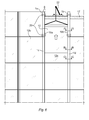
- Figure 6 shows an elevational view of a part of a multi-store building on which facade elements are mounted with a method according to the invention. Further, the figure illustrates transportation of a facade element 12 during mounting of the facade.
- the building comprises a number of vertical, load-bearing walls (not shown) as well as a number of horizontal, between the walls extending floors 17, also denoted slabs.
- the facade element 12 comprises a first main side and a second main side, which are essentially parallel to each other.
- the facade element also comprises a first edge 18a and a second edge 18b. Each of the edges 18a-b includes a protruding part 13.
- a plurality of horizontally aligned facade elements is mounted on one floor.
- a number of vertical profiles 1a-d of the first type is attached to the floors of the building.
- the vertical profiles are arranged above each other so that the longitudinal axes of the profiles are aligned, thereby forming columns of vertical profiles.
- a plurality of columns of vertical profiles is arranged in parallel and at a horizontal distance from each other which essentially correspond to the width of the facade elements.
- Two neighbouring columns of vertical elements 1 are arranged so that the slots are facing each other.
- Facade elements 12b-c are mounted between two neighbouring columns of profiles.
- Figure 4 shows a cross section C-C through the mounted facade elements and the vertical profiles.
- the mounted facade elements are supported by vertical profiles 14 of the second type, as shown in figure 4 , which have been entered into the outer parts 6 of the slots of the vertical profiles 1 of the first type.
- the vertical profiles of the first and second type are mounted so that they are allowed to receive the facade element from below and to support the edges of the facade element when the facade element is transported to the mounting position.
- Supporting profiles 8 extend
- FIG. 5 shows a cross section B-B through the facade element 12 when it is guided by the grooves 15 of the vertical profile of the second type.
- FIG. 1 is a cross section A-A through the facade element 12 and the vertical profile 1.
- the facade element 12 is moved guided by the outer parts 6 of the slots in a vertical direction towards the mounting position.
- a tool 20 is mounted on each of the two neighbouring vertical profiles 1 and 1b on the last floor where the facade is being mounted. The tool 20 is used for pushing the facade element 12 from the outer part 6 of the slots to the inner parts 5 of the slots.
- the tools 20 are arranged in the supporting profiles 8 that extend along the length of the vertical profiles 1a,1b, and the tool is allowed to move along the notches 9 between the supporting profiles.
- the facade element 12 is vertically moved by means of a lifting device 22 positioned on the floor at which the facade element is to be mounted or on a floor above the floor at which the facade element is to be mounted.
- the lifting device is, for example, a mini crane.
- Figure 7 illustrates how a correct distance between two vertical profiles of the first type 1a-b is ensured by means of a jig 23 having a length that corresponds to the length of the facade element to be mounted.
- the jig 23 has the form of a bar. By using the jig a correct distance and parallelism between the two vertical profiles 1a-b is ensured.
- the jig is removed and can be used for mounting the next vertical profile 1.
- the jig is arranged to be engaged to the upper parts of two vertical profiles arranged at a distance from each other.
- the jig 23 is provided with one or more holes in each of its ends having a size that corresponds to the size of the protruding pins 27 of the vertical elements.
- the holes on one of the ends of the jig are threaded on the pins of an already mounted vertical element 1a and the holes on the other end of the jig is thread on the vertical profile 1 b, which is to be mounted.
- Figure 8a shows a perspective view of a vertical profile 1 of the first type provided with a fastening device 24 comprising a first fastening element 25 for fastening to the fastening member 28 on the building, and a second fastening element 26 for fastening the facade element.
- the fastening device 24 is preassembled to the vertical profile 1 before delivery to the building site.
- the fastening device 24 is shown in a view from behind in figure 8c .
- the fastening device 24 is provided with two second fastening elements 26 for fastening two facade elements, which are mounted on opposite sides of the vertical profile 1 to the building.
- For fastening the facade element 12 to the building at least two second fastening elements 26 are needed; one for each edge 18a-b.
- the fastening device 24 comprises a common load-bearing body 34 and the first and second fastening elements 25, 26 are provided on the load-bearing body.
- the upper part of the vertical profile 1 is provided with protruding pins 27 adapted to be inserted in corresponding holes provided on the lower part of the next vertical profile to be mounted above the vertical profile.
- the figure further shows a floor 17 of the building. On the floor 17 is mounted a fastening member 28 adapted to be engaged to the first fastening element 25 on the vertical profile 1.
- the fastening member 28 comprises a vertically extending portion 30, and the first fastening element 25 comprises a slot 32 designed to receive the portion 30 of the fastening member 28 thereby providing an engagement between the first fastening member 28 and the first fastening device 24.
- the first fastening element 25 is engaged to the vertically extending portion 30 of the fastening member 28, as shown in figure 8b .
- the first fastening element 25 is then clamped to the portion 30 of the fastening member 28.
- the vertical profiles are mounted so that they extend a distance above the floor to which they are mounted, which, for example, facilitates mounting of the sealing strip as described with reference to figure 19 .
- the joint can be align with the floor.
- Figure 9a shows a rear elevational view of a facade element 12 provided with a fastening unit 35, for attaching the facade element to the second fastening element 26 and thereby to the building.
- Figure 9b shows a perspective view of the facade element 12 and the fastening device 24.
- the fastening unit 35 includes a pin 36 provided in a recess 37 of the edge of the facade element 12.
- the upper part of the recess 37 is provided with a metal plate 38 to reinforce the recess.
- the facade element 12 is provided with one fastening unit 35 in each of its edges 18a-b.
- the second fastening element 26 is designed to be engaged to the fastening unit 35 provided on the facade element.
- the second fastening element 26 is designed as a hook adapted to receive the pin 36 of the fastening unit 35.
- the fastening units 35 on each side of the facade element are engaged to the second fastening elements 26 of the fastening devices 24, which has been engaged to the floor when the vertical profiles 1a,1b were previously mounted. By that the facade element is attached to the floor of the building.
- Figure 10 shows one edge 18a of the facade element attached to the floor 17 of the building by means of the fastening device 24 and the fastening member 28.
- the other opposite edge 18b of the facade element is attached to the floor 17 of the building in the same way as shown in figure 10 by means of a fastening device, a fastening member, and fastening unit.
- Figures 11 and 12 illustrate mounting of a tool for pushing the facade element from the outer part of the slot to the inner part of the slot of the vertical profile of the first type.
- the facade element When the facade element has reached its mounting position, or close to the mounting position, the facade element must be moved from the outer part 6 to the inner part 5 of the slots.
- a press power is needed in order to overcome the resistance due to friction from the flexible elements 7 on the vertical profile 1.
- a specially designed tool is used for performing this step.
- This can, for example, be done by a tool 20 including one or more eccentrically supported discs 58,60 arranged at a vertical distance from each other, as shown in figures 11 and 12 .
- the tool 20 may have only one disc, or more than two discs.
- the discs are shaped so that the difference between the minimum and maximum radius of the disc corresponds to the horizontal movement that is required for pushing the facade element from the outer part 6 of the slot to the inner part 5 of the slot.
- the disc is provided with a plane surface adapted to bear on the facade element.
- the plane surface of the disc is covered with a low friction material, and the curved surface is covered with a high friction material.
- the angular movement of the disc is stopped when the plane surface of the disc is in parallel with the facade element, as shown in figure 17b .
- the discs are designed so that the discs rotate due to friction when they are in contact with the facade element when the facade element is moved downwards.
- the facade element is moved downwards due to its own weight when the gravity force is acting on the element. Accordingly, the dead weight of the facade element is used to achieve the press power needed to move the facade element from the outer to the inner part of the slots.
- the tool disclosed in figure 11 and 12 is provided with two pair of discs 58,60 adapted to be arranged on opposite sides of the vertical element 1 in order to act on facade elements on both sides of the vertical element. This reduces the number of times the tool has to be moved.
- a facade element has been mounted, only one of the tools has to be moved to the mounting position of the next facade element to be mounted.
- the angular positions of the discs are synchronized by means of a transmission (not shown), for example chain or a synchronous transmission belt.
- Figure 11 illustrates how the tool 20 is inserted into the groove 9 of one or more of the supporting profiles 8 of the vertical profile 1 of the first type, which has been mounted on the building.
- Figure 12 illustrates how one pair of discs 60 is moved downward in the supporting profile 8 until it reaches the lower part of the vertical profile 1.
- the other pair of discs 58 is positioned at the upper part of the vertical profile 1.
- One tool 20 is mounted on each of the two vertical profiles arranged neighbouring each other for supporting the facade element.
- the facade element 12 is moved upward until it comes into contact with the lower discs 60 of the tools, as shown in figure 13 and figure 15a .
- the facade element 12 will turn away the discs 60 and 58 so that the contact between the facade element and the discs are made where the discs have their smallest radius, and accordingly the facade element 12 without hindrance can pass by the discs 58, 60, whose surfaces slide against the facade element, as shown in figure 15b .
- the upward movement of the facade element affects the discs 58, 60 so that the discs are turned into a working position, i.e. the discs are rotated until they reach their smallest radius, as shown in figure 15b .
- the facade element 12 is further moved upward to a position above the final mounting position, as shown in figure 14 .
- the facade element 12 is lowered towards the final mounting position, as shown in figure 16a , and at the same time the discs 58,60 are driven to push the facade element towards the inner part of the slots.
- the discs 58, 60 are caused to rotate to their largest radius by the movement of the facade element, as shown in figure 17a .
- the discs push the facade element towards the inner part of the slot.
- the discs are rotated until they reach their largest radius.
- the facade element 12 When the discs have reached their largest radius the facade element 12 is close to the final mounting position, and the facade element is vertically moved, as shown in figure 17a-b , until the fastening units 35 on the facade element are engaged to the second fastening elements 26 on the vertical profiles 1a-b and thereby the facade element is attached to the floor of the building, as shown in figure 9b, 10 , and 16b .
- the facade element 12 is now positioned in the inner parts 5 of the slot and engaged to the fastening elements 26 of the vertical profiles 1a-b of the first type.
- the discs 58, 60 have released contact with the facade element and the tool can be removed from the vertical profile 1.
- the next step is to insert vertical profiles of the second type 14 into the outer parts 6 of the slots of the two vertical profiles supporting the facade element, as shown in figure 3 and 4 .
- the profiles 14 of the second types are secured by ropes attached to the upper ends of the profiles 14.
- the profiles 14 are lowered along the vertical profiles 1a-b of the first type until they are positioned at a determined horizontal position close to the mounting position.
- the profiles 14 are inserted into the outer parts 6 of the slot of the vertical profiles 1a-b so that the vertical profile 14 is bearing on the surface of facade element 12 and the surface 11 of the outer part 6 of the slot.
- the profile 14 is attached to the profile 1, for example, by means of a screw-joint or a snap-fit joint.
- the mounting of the vertical profile 14 of the second type can preferably be made by using a specially designed mounting tool.
- Figures 18a-c and 19 illustrate the steps of providing a horizontal sealing between the facade elements on different floors.
- a continuous sealing strip 70 is provided on top of the facade elements and the vertical profiles.
- a adaptor block 65 is mounted on the top each of the vertical profiles of the first type 1 on the floor.
- the adaptor block 65 is designed to fit between the facade elements 12, 12b on each side of the vertical profile 1 and to achieve a support for the seal 70 where it is not supported by the upper edge of facade element.
- the upper side of the adaptor block 65 has a profile that corresponds to the upper side of facade element.
- the adaptor block 65 is provided with two parallel guiding rails 66, 67 adapted to support and guide the sealing strip 70.
- Figure 18a shows the adaptor block 65 before mounting and figure 18b shows the adaptor block when it is mounted to the top of the vertical profile 1.
- Figure 18c shows the mounting of the sealing strip 70.
- Figure 20 shows the whole line of transportation of facade elements 12 from delivery by truck trailer to the base of the building to the installation place on the building.
- the first row of vertical profiles is mounted at a distance from the base of the building in order to make it possible to insert the facade elements into the profiles.
- a conveyer system including a conveyer track 72 is arranged around the building for providing horizontal transportation of the facade elements.
- the conveyer track is running around, at least a part of the building, and preferably around the entire building.
- the conveyer system is mounted close to the lower part of the vertical profiles of the first floor, which is to be provided with facade elements.
- the conveyer system comprises equipment for automatically unloading facade elements from the truck trailer in an unloading position, and an intermediate storage 74 of the facade elements, and horizontal transportation of facade elements from the intermediate storage 74 to a desired horizontal position.
- a facade element reaches the desired horizontal position, the facade element is vertically moved to the mounting position guided by the grooves of the second type of profiles mounted on the building.
- Figure 21 shows an example of how a facade element is transferred from the conveyer system to an elevator unit 80.
- Figure 22 shows a facade element transported upward with its edges entered into the grooves of the vertical profiles of the second type.
- the facade elements are moved from the conveyer truck to the vertical profiles by means of an elevator unit 80 provided with a gripping device for gripping the facade elements.
- the gripping device is arranged to move the facade element in a direction towards the building thereby facilitating the insertion of the facade element into the grooves 15 of the second type 14 of vertical profile.
- the elevator unit 80 has been lowered to the lower ends of the vertical elements 1.
- the conveyer track 72 positions the facade element 12 below the elevator unit 80, as shown in figure 21 .
- a lower part of the elevator unit 80 begins to angle outward from the facade in a direction towards the facade element 12 to be mounted.
- the gripping device has been turned out far enough to grip the upper part of the facade element.
- the facade element is released from the conveyer track and the facade element is moved inwards towards the building when the lower part of the elevator unit is angled to a straight position.
- the upper edge of the facade element enters the grooves of the profile of the second type and the lifting device moves the elevator unit with the facade element to a desired mounting position.
- the facade element is guided by the grooves of the underlying already mounted profiles of the second type.
Landscapes
- Engineering & Computer Science (AREA)
- Architecture (AREA)
- Civil Engineering (AREA)
- Structural Engineering (AREA)
- Mechanical Engineering (AREA)
- Physics & Mathematics (AREA)
- Electromagnetism (AREA)
- Conveying And Assembling Of Building Elements In Situ (AREA)
- Finishing Walls (AREA)
- Load-Bearing And Curtain Walls (AREA)
Abstract
Description
- The present invention relates to a method for mounting facade elements on a multi-storey building.
- Multi-storey buildings may be constructed in a plurality of ways. Common for all of them is that they comprise a facade. The facade may be provided in a large number of different ways and may either constitute a load bearing part of the multi-storey building or only serve as weather protection. In the latter case the building comprises a building structure on which plate formed facade elements are attached. The plate formed facade elements may comprise one or more different kinds of facade elements.
- The facade elements are often transported to the working site on pallets. These pallets are traditionally off-loaded from a de- livery truck by a tower crane and then lifted to the floor where the facade elements will be installed. The tower crane is a critical resource. Waiting time for trucks and tower cranes generate waste time and substantial costs.
- The handling of the facade elements during mounting on the building is sensitive and facade elements may be damaged during handling. During hoisting of facade elements there is a risk for the elements to crash into earlier mounted elements or other parts of the building or nearby equipment and damages may arise. These risks increase during mounting in windy conditions, which may lead to a standstill in the facade installation process while awaiting calmer weather.
- The facade elements are usually lifted to the installation level on the building using tower cranes which have the purpose of lifting building material to different parts of the building. The methods used for installation is either direct assembly of facade elements one by one by the tower crane, or using the tower crane for lifting pallets of façade elements to the installation floor from which final installation is made using mobile mini cranes one floor above installation level. The positioning of panels on the floors is a problem since staged panels occupy space on each floor that must be left unobstructed by other trades, and also requires detailed instructions from the structural designer due to limited early concrete strength. Both these methods is weather dependent and hoisting large facade elements using the tower crane is a critical resource.
- In "De-coupling cladding installation from other high-rise building trades: a case study, proc. 9th Annual conference of the International group for lean construction - IGLC 9, Singapore, 6-8 August 2001", a method for hoisting facade elements on a multistorey building without the use of tower cranes is described. For hoisting of facade elements one or more cranes are described which can successively be placed on the floors during the erection of the building and which comprises supports for a cable guided lifting device in which the facade element may be transported to the desired height in the building. The facade elements can then be distributed horizontally to the desired place using a traverse collar arranged to be temporarily anchored on the building structure around the entire building and which may be moved continuously upward in the building. After finishing mounting of facade elements all parts which have been intended for hoisting and distribution of facade elements to the intended place will be dismantled and may thereby not be used for other purposes regarding the building.
-
US Patent 4 591 308 discloses another method for hoisting facade elements on a multi-storey building without the use of tower cranes. The patent discloses a guide jig for lifting facade elements. The guide jig is suspended from a rope and is guided in vertical rails provided on the outside of each facade element. When the facade element reaches the floor on which it is to be mounted the facade element is moved towards the building by the tower crane and a mechanical arm provided on the jig. A drawback with this method is that the facade element is not guided by the vertical rails on the previously mounted elements when the element reaches the floor on which it is to be mounted. Further, to move the facade element into its mounting position is complicated and involves a number of mounting steps. -
GB22284009 - The object of the present invention is to provide an improved method for mounting facade elements on a multi-storey building which alleviates the drawbacks mentioned above.
- This object is achieved by the method as defined in
claim 1. - The method uses a profile system comprising a first type of vertical profile having a slot extending along the longitudinal axis of the profile, and an inner part of the slot being designed to receive an edge of a first facade element and an outer part of the slot is designed to receive and support a second type of vertical profile arranged to support the first facade element, and the second type of profile is provided with a groove extending along the longitudinal axis of the profile and designed to receive and support an edge of a second facade element. The method comprises:
- a) mounting two vertical profiles of the first type at a second floor of the building so that the slots are facing each other, and above profiles of the first and second types previously mounted on a first floor so that the longitudinal axes of the profiles are aligned,
- b) transporting a facade element in a vertical direction guided by the grooves of the second type of profiles mounted on the first floor until it reaches the vertical profiles mounted on the second floor,
- c) entering the facade element into the outer part of the slots of the vertical profiles mounted on the second floor,
- d) continuing transporting the facade element in a vertical direction guided by the outer part of the slots of the vertical profiles mounted on the second floor until it reaches a mounting position,
- e) pushing the facade element from the outer part of the slots to the inner part of the slots,
- f) attaching the facade element to the building, such as a floor structure of the building, and
- g) inserting vertical profiles of the second type into the outer part of the slots so that the grooves are facing each other.
- An advantage with the method according to the invention is that the facade element is supported all the way up to the mounting position and during the mounting of the facade element to the building. During transportation of the facade element to the floor below the present mounting position, the facade element is guided by the grooves of the second type of vertical elements, which also support the facade element mounted on the previous floor. When the facade element leaves the grooves on the floor below the present mounting position, the facade element is supported by the outer part of the slots of the vertical profiles mounted on the present floor during transportation as well as during mounting of the facade element. The outer part of the slots prevents the facade element from swinging away from the building due to windy weather. This enables a safe mounting not affected by bad weather conditions. Further, the method according to the invention enables safe mounting of large facade elements, in particular facade elements having a large width.
- The method according to the invention is simple, fast, and accordingly reduces the time needed for mounting the facade elements, and accordingly considerably lowers the mounting costs.
- The method further comprises: mounting two vertical profiles of the first type at a third floor of the building, so that the slots are facing each other, and above the profiles of the first and second type previously mounted on the second floor so that the longitudinal axes of the profiles are aligned, and transporting a second facade element, guided by the grooves of the second type of vertical profiles, in a vertical direction until it reaches the vertical profiles mounted on the third floor, and repeating the steps c-g for the second facade element. The facade elements are transported one by one on the outside of the previously mounted facade elements to the floor on which it is to be mounted. No on-floor staging is needed since the facade elements are transported directly to the installation position, thereby reducing the used working space inside the building.
- According to an embodiment of the invention, the second facade element is pushed from the outer part of the slots to the inner part of the slots by means of a tool. Such a tool can be made much cheaper than the previously mentioned pneumatically controlled system for moving the facade elements to its mounting position. As no expensive equipment is needed it is possible to simultaneously mount a plurality of facade elements on different horizontal positions along the building.
- The method further comprises attaching a tool to at least one of said two vertical profiles on the second floor, and steps d and e further comprises moving the facade element upward until it comes into contact with the tool, moving the facade element upward to a position above the final mounting position, while the upward movement of the facade element affects the tool so that the tool is turned into a working position, and lowering the facade element towards the final mounting position causing the tool to push the facade element towards the inner part of the slots. The tool makes it possible to push the facade element to the final mounting position without having any person on the outside of the building. The personnel only has to mount the tool on the vertical profile from inside of the building, and to control the upward and downward vertical movements of the facade element, and the facade element will be pushed to its final mounting position by the mechanics contained within the tool.
- According to an embodiment of the invention, the tool is driven by a vertical down movement of the facade element. Thus, the tool does not have to be provided with a drive of its own, which reduces the cost of the tool.
- According to an embodiment of the invention, the vertical profiles of the first type are provided with a first fastening element designed to be engaged to a corresponding fastening member on the building, and a second fastening element designed to be engaged to a corresponding fastening unit provided on the facade element, and step a further comprises: providing the second floor with at least two fastening members arranged at a distance from each other, and attaching the vertical profiles of the first type to the second floor by engaging the first fastening elements to the fastening member on the second floor, and step f comprises attaching the facade element to the building by engaging the fastening units of the facade element to the second fastening elements of the vertical profiles. Preferably, the fastening elements are attached beforehand to the vertical profiles.
- This embodiment simplifies the mounting of the facade element in that the second fastening element is already mounted to the vertical profiles, and does not have to be mounted to the floor of the building. Accordingly, the step of mounting fastening elements to the building is omitted. However, if the facade element is very wide it is possible to provide one or more extra fastening elements of a different type on the floor between the vertical elements and corresponding fastening units on the facade element to support the middle part of the facade element. Further, the positioning of the facade element with respect to the building is facilitated, as the vertical profiles have a defined position with respect to the building when the first fastening elements are engaged to the fastening members of the building, and the facade element has a defined position with respect to the vertical profiles when the second fastening elements are engaged to the fastening units on the facade element.
- According to an embodiment of the invention, the first and second fastening elements are integrated in a single unit and comprise a common load bearing body. This embodiment facilitates the mounting of the fastening elements to the vertical profile. Further, the common load bearing body transfers the weight of the facade element to the fastening member on the building, and thus of the weight of the facade element is carried by the building, and not by the vertical profile.
- According to an embodiment of the invention, the facade elements are delivered to the building by a truck trailer, and the method comprises automatically moving the facade elements from the truck trailer to a storage position located at a base of the building. Further, the method comprises transporting the facade elements from the storage position to a desired horizontal position by means of a conveyer system including a track arranged around at least a part of the building. On-site transport will be minimized by lifting the facade elements directly from the truck trailer and forwarding them to their installation position, without any interim on-floor staging. This avoids internal transportations. Further, the risk of damaging the facade elements is reduced since no on-ground or on-floor staging is necessary and because there is full control over the transports of the facade elements.
- According to an embodiment of the invention, the facade elements are vertically moved by means of a lifting device, for example a mini crane, positioned on the floor at which the facade element is to be mounted or on a floor above the floor at which the facade element is to be mounted. A general multi-purpose lifting device can be used for vertical movements of the facade element. Thus, no specially designed drive unit is needed for the vertical movements of the facade element.
- According to an embodiment of the invention, the facade elements are moved by means of an elevator unit provided with a gripping device for gripping the facade element, the gripping device being arranged to move the facade element so that the edges of the facade element are aligned with the grooves of the second type of vertical profiles mounted on the building thereby facilitating the insertion of the facade element into the grooves of the second type of vertical profiles, and the method comprises gripping the facade elements by means of the elevator unit, and inserting the second facade element into the grooves of the second type of vertical profiles by means of the elevator unit. Accordingly, the insertion of the facade element into the grooves of the second type of vertical profiles can be made automatically, and can be controlled by a worker standing at a distance from the insertion position, for instance at the foot of the building.
- Further, the elevator unit is guided by the grooves of the second type of vertical profiles, and the elevator is vertically moved by the lifting device. Thus, the elevator does not need to have any drive system of its own. A general multi-purpose lifting device can be used.
- According to an embodiment of the invention, the method comprises transporting the facade elements from the storage position to the elevator unit by means of the conveyer system. A flow of facade elements from delivery by the truck to installation is provided and a continuous flow of facade elements from delivery to installation is enabled. Thereby, contractors will not be subject to unnecessary handling of the facade elements, or have to wait for tower cranes or other trades. This means that the facade contractor is virtually independent of the site's common shared cranes and building hoists.
- According to an embodiment of the invention, a correct distance between the two vertical profiles of the first type during mounting of the profiles is ensured by means of a jig having a length that corresponds to the width of a facade element. This embodiment makes it quick and easy to mount the vertical profiles with a correct distance between them.
- According to an embodiment of the invention, said first type of vertical profile has a second slot extending along the longitudinal axis of the profile on an opposite side of the profile with respect to the first mentioned slot, and the second slot has an inner part designed to receive an edge of a facade element and an outer part designed to receive the second type of vertical profile, and the method comprises mounting one vertical profile of the first type at a horizontal distance from one of the profiles of the second floor so that the slots are facing each other, and above one profile previously mounted on a first floor so that the longitudinal axes of the profiles are aligned, and repeating the steps b-g. One vertical profile of the first type can be used for mounting two horizontally aligned facade elements, which facilitates the mounting.
- According to an embodiment of the invention, the method further comprises mounting a adaptor block on top of the vertical profiles of the first and second type and between two aligned facade elements, mounting a continuous sealing strip on top of two horizontally aligned facade elements and on top of the adaptor block in order to seal between facade elements and vertical profiles of different floors, and thereafter mounting the facade elements on the next floor above the sealing strip. The sealing strip extends continuously over a plurality of facade elements and vertical profiles. This embodiment ensures a safe horizontal sealing between the facade elements.
- The invention will now be explained more closely by the description of different embodiments of the invention and with reference to the appended figures.
- Fig. 1
- shows a cross-sectional view of an example of a vertical profile of a first type.
- Fig. 2
- shows a cross-sectional view of an example of a facade element guided by an outer part of a slot in the vertical profile shown in
figure 1 - Fig. 3
- shows a cross-sectional view of the facade element when it has been moved to an inner part of the slot, and a vertical profile of a second type.
- Fig. 4
- shows a cross-sectional view of two facade elements held by the vertical profile of the first type and supported by vertical profiles of the second type.
- Fig. 5
- shows a cross-sectional view of a facade element guided by a groove in the vertical profile of the second type.
- Fig. 6
- shows a elevational view of a part of multi-storey building on which facade elements are mounted with a method according to the invention.
- Fig. 7
- illustrates how a correct distance between two vertical profiles of the first type is ensured by means of a jig.
- Fig. 8a
- shows a perspective view of a vertical profile of the first type provided with a fastening device and a floor of a building provided with a fastening member.
- Fig. 8b
- shows a perspective view of a vertical profile of the first type fastened to the floor of a building by means of the fastening device and the fastening member.
- Fig. 8c
- shows a perspective view of the fastening device.
- Fig. 9a
- shows a side view of a facade element provided with a fastening unit and a fastening device.
- Fig. 9b
- shows an elevational view of the facade element provided with a fastening unit and the fastening device.
- Fig. 10
- shows a perspective view of a facade element and a vertical profile of the first type attached to the floor of the building by means of a fastening device.
- Figs. 11-12
- illustrate mounting of a tool for pushing the facade element from the outer part of the slot to the inner part of the slot of the vertical profile of the first type.
- Figs. 13,14,15a-b,16a-b, and 17a-b
- illustrate mounting of a facade element by means of the tool.
- Figs. 18a-c and 19
- illustrate the steps of providing a seal between the facade elements.
- Fig. 20
- shows the whole line of transportation of facade elements from delivery to the foot of the building to the installation place on the building.
- Fig. 21
- shows an example of how a facade element is transferred from a conveyer system to an elevator unit.
- Fig. 22
- shows a facade element transported upward with its edges entered into the grooves of the vertical profiles of the second type.
-
Figure 1 shows a cross-section through an example of avertical profile 1 of a first type. Thevertical profile 1 has a cross-section, which is essentially constant along the length axis of the profile. Thevertical profiles 1 are of corresponding lengths to the facade element. Theprofile 1 comprises afirst portion 2, which is arranged to be placed facing the building, and asecond portion 3, which is arranged to be placed facing away from the building. Aslot 4a-b is arranged between the first and second portion on each side of thevertical profile 1. Theslots 4a-b extend along the longitudinal axis of theprofile 1. Each of the slots is divided into aninner part 5 and anouter part 6. Theinner part 5 of the slot is designed to receive and house an edge part of a facade element, and theouter part 6 of the slot is designed to receive and support a second type ofvertical profile 14, as shown infigure 3 . The edge part can also be an adapter provided on the edges of the facade element in order to adapt it to the profile system. Theinner part 5 of the slot is provided with a plurality offlexible elements 7. Theflexible elements 7 are made of a resilient material and are arranged to support, centre, and seal the facade element when it is mounted, as shown infigure 3 . - The
second portion 3 comprises an outer surface on which there is arranged a plurality of supportingprofiles 8, which extend along the longitudinal axis of theprofile 1, and between which notches 9 are arranged. The supportingprofiles 8 may be used to guide one or more supporting devices. Thefirst portion 2 comprises aninner surface 10 facing theinner part 5 of the slot, and thesecond portion 3 comprises aninner surface 11 facing theouter part 6 of the slot. Thevertical profile 1 is symmetrical with respect to a symmetry axis that extends through the first andsecond portions vertical profile 1 can have different designs. Another example of a vertical profile of the first type suitable for mounting by means of the method according to the invention is disclosed inWO2009/093948 . In this example, the edges of the facade element does not have a protruding part, instead the whole edge of the facade element is entered into the slot. -
Figure 2 shows a cross-sectional view of a part of afacade element 12 supported by theouter part 6 of the slot in thevertical profile 1.Figure 2 is a cross-section A-A through the mounting shown infigure 6 . The facade elements may comprise glass plates, or laminated glass, one or more weatherproof plates or a combination of glass plates and weatherproof plates and may also comprise a frame which holds the glass plates and/or the weatherproof plates. A combination of different plate formed facade elements may be used for the facade. The edge of thefacade element 12 is provided with a protrudingpart 13 extending along the entire length of the facade element. The protrudingpart 13 of the edge of the facade element is located in the outer part of theslot 6. The opposite edge of the facade element is provided with a corresponding protruding part (not shown), which is located in the outer part of the slot of another vertical element of the first type arranged at a distance from the first vertical element. Accordingly, thefacade element 12 is supported by theouter parts 6 of the slots and the facade element is thereby prevented from swinging away from the building. -
Figure 3 shows thefacade element 12 when it has been moved from theouter part 6 to theinner part 5 of the slot of thevertical profile 1. The protrudingpart 13 of the edge of the facade element is bearing on thesurface 10 of thefirst portion 2. Theflexible members 7 support thefacade element 12.Figure 3 also shows avertical profile 14 of a second type, which is designed to fit in theouter part 6 of the slot, and arranged to support thefacade element 12 when it has been mounted. Thevertical profile 14 of the second type is named a U-profile. Thevertical profile 14 of the second type is provided with agroove 15 extending along the longitudinal axis of the profile and designed to receive and support the protrudingedge part 13 of a facade element. Thegroove 15 is named a U-groove. Thevertical profile 14 has a cross-section, which is essentially constant along the length axis of the profile. The length of thevertical profile 14 of the second type is essentially the same as the length of thevertical profile 1 of the first type. Theprofile 14 of the second type is arranged to be placed so that it supports thefirst facade element 12. Theprofile 14 is designed to bear on thesurface 11 of thesecond portion 3 on theprofile 1 when it is mounted, as shown infigure 4 . -
Figure 4 shows a cross-section through twofacade elements facade elements vertical profile 1 of thefirst type 1 and twovertical profiles 14 of the second type.Figure 4 is a cross-section C-C through the mounting shown infigure 6 . -
Figure 5 shows a cross-section through afacade element 12c, which is on its way to its mounting position. Thefacade element 12c is guided by thegroove 15 of thevertical profile 14 of the second type when it is vertically moved. Thefacade elements facade element 12c is vertically moved to its mounting position on the outside of thefacade elements part 13, which is guided by a correspondinggroove 15 in avertical profile 14 of the second type arranged in aprofile 1 of the first type in the same way as shown infigure 5. Figure 5 is a cross-section B-B through the mounting shown infigure 6 . -
Figure 6 shows an elevational view of a part of a multi-store building on which facade elements are mounted with a method according to the invention. Further, the figure illustrates transportation of afacade element 12 during mounting of the facade. The building comprises a number of vertical, load-bearing walls (not shown) as well as a number of horizontal, between thewalls extending floors 17, also denoted slabs. Thefacade element 12 comprises a first main side and a second main side, which are essentially parallel to each other. The facade element also comprises afirst edge 18a and asecond edge 18b. Each of theedges 18a-b includes a protrudingpart 13. A plurality of horizontally aligned facade elements is mounted on one floor. - A number of
vertical profiles 1a-d of the first type is attached to the floors of the building. The vertical profiles are arranged above each other so that the longitudinal axes of the profiles are aligned, thereby forming columns of vertical profiles. A plurality of columns of vertical profiles is arranged in parallel and at a horizontal distance from each other which essentially correspond to the width of the facade elements. Two neighbouring columns ofvertical elements 1 are arranged so that the slots are facing each other.Facade elements 12b-c are mounted between two neighbouring columns of profiles.Figure 4 shows a cross section C-C through the mounted facade elements and the vertical profiles. The mounted facade elements are supported byvertical profiles 14 of the second type, as shown infigure 4 , which have been entered into theouter parts 6 of the slots of thevertical profiles 1 of the first type. The vertical profiles of the first and second type are mounted so that they are allowed to receive the facade element from below and to support the edges of the facade element when the facade element is transported to the mounting position. Supportingprofiles 8 extend along the length of the vertical profiles of the first type. - When a
facade element 12 is to be transported to its mounting position, the protrudingparts 13 of theedges 18a-b of the facade element are inserted into thegrooves 15 of the lowest vertical profiles of the second type of two neighbouring columns of vertical profiles. Thefacade element 12 is vertically moved to the mounting position guided by thegrooves 15 of the vertical profiles of the second type previously mounted on the floors below the floor of the mounting position.Figure 5 shows a cross section B-B through thefacade element 12 when it is guided by thegrooves 15 of the vertical profile of the second type. - When the facade element reaches the
vertical profiles parts 13 of theedges 18a-b of thefacade element 12 are inserted into theouter parts 6 of the slots of theprofiles figure 2. Figure 2 is a cross section A-A through thefacade element 12 and thevertical profile 1. Thefacade element 12 is moved guided by theouter parts 6 of the slots in a vertical direction towards the mounting position. In this embodiment, atool 20 is mounted on each of the two neighbouringvertical profiles tool 20 is used for pushing thefacade element 12 from theouter part 6 of the slots to theinner parts 5 of the slots. Thetools 20 are arranged in the supportingprofiles 8 that extend along the length of thevertical profiles facade element 12 is vertically moved by means of alifting device 22 positioned on the floor at which the facade element is to be mounted or on a floor above the floor at which the facade element is to be mounted. The lifting device is, for example, a mini crane. -
Figure 7 illustrates how a correct distance between two vertical profiles of thefirst type 1a-b is ensured by means of ajig 23 having a length that corresponds to the length of the facade element to be mounted. Thejig 23 has the form of a bar. By using the jig a correct distance and parallelism between the twovertical profiles 1a-b is ensured. When the vertical profile has been mounted the jig is removed and can be used for mounting the nextvertical profile 1. The jig is arranged to be engaged to the upper parts of two vertical profiles arranged at a distance from each other. Thejig 23 is provided with one or more holes in each of its ends having a size that corresponds to the size of the protruding pins 27 of the vertical elements. When the jig is used, the holes on one of the ends of the jig are threaded on the pins of an already mountedvertical element 1a and the holes on the other end of the jig is thread on thevertical profile 1 b, which is to be mounted. - Now an inventive method for fastening the
vertical profiles 1 of the first type and thefacade elements 12 to the building will be described with reference to thefigures 8a-c ,9a-b and 10 . -
Figure 8a shows a perspective view of avertical profile 1 of the first type provided with afastening device 24 comprising afirst fastening element 25 for fastening to thefastening member 28 on the building, and asecond fastening element 26 for fastening the facade element. Preferably, thefastening device 24 is preassembled to thevertical profile 1 before delivery to the building site. Thefastening device 24 is shown in a view from behind infigure 8c . In this embodiment, thefastening device 24 is provided with twosecond fastening elements 26 for fastening two facade elements, which are mounted on opposite sides of thevertical profile 1 to the building. For fastening thefacade element 12 to the building at least twosecond fastening elements 26 are needed; one for eachedge 18a-b. Thefastening device 24 comprises a common load-bearing body 34 and the first andsecond fastening elements - The upper part of the
vertical profile 1 is provided with protrudingpins 27 adapted to be inserted in corresponding holes provided on the lower part of the next vertical profile to be mounted above the vertical profile. The figure further shows afloor 17 of the building. On thefloor 17 is mounted afastening member 28 adapted to be engaged to thefirst fastening element 25 on thevertical profile 1. Thefastening member 28 comprises a vertically extendingportion 30, and thefirst fastening element 25 comprises aslot 32 designed to receive theportion 30 of thefastening member 28 thereby providing an engagement between thefirst fastening member 28 and thefirst fastening device 24. During mounting of thevertical profile 1, thefirst fastening element 25 is engaged to the vertically extendingportion 30 of thefastening member 28, as shown infigure 8b . Thefirst fastening element 25 is then clamped to theportion 30 of thefastening member 28. As shown infigures 8a-b andfigure 6 the vertical profiles are mounted so that they extend a distance above the floor to which they are mounted, which, for example, facilitates mounting of the sealing strip as described with reference tofigure 19 . However, in an alternative embodiment of the invention, the joint can be align with the floor. -
Figure 9a shows a rear elevational view of afacade element 12 provided with afastening unit 35, for attaching the facade element to thesecond fastening element 26 and thereby to the building.Figure 9b shows a perspective view of thefacade element 12 and thefastening device 24. In this embodiment thefastening unit 35 includes apin 36 provided in arecess 37 of the edge of thefacade element 12. The upper part of therecess 37 is provided with ametal plate 38 to reinforce the recess. Thefacade element 12 is provided with onefastening unit 35 in each of itsedges 18a-b. Thesecond fastening element 26 is designed to be engaged to thefastening unit 35 provided on the facade element. In this embodiment, thesecond fastening element 26 is designed as a hook adapted to receive thepin 36 of thefastening unit 35. During mounting of thefacade element 12, thefastening units 35 on each side of the facade element are engaged to thesecond fastening elements 26 of thefastening devices 24, which has been engaged to the floor when thevertical profiles -
Figure 10 shows oneedge 18a of the facade element attached to thefloor 17 of the building by means of thefastening device 24 and thefastening member 28. The otheropposite edge 18b of the facade element is attached to thefloor 17 of the building in the same way as shown infigure 10 by means of a fastening device, a fastening member, and fastening unit. -
Figures 11 and 12 illustrate mounting of a tool for pushing the facade element from the outer part of the slot to the inner part of the slot of the vertical profile of the first type. When the facade element has reached its mounting position, or close to the mounting position, the facade element must be moved from theouter part 6 to theinner part 5 of the slots. A press power is needed in order to overcome the resistance due to friction from theflexible elements 7 on thevertical profile 1. - According to an embodiment of the invention, a specially designed tool is used for performing this step. This can, for example, be done by a
tool 20 including one or more eccentrically supporteddiscs figures 11 and 12 . In alternative embodiments of the invention, thetool 20 may have only one disc, or more than two discs. The discs are shaped so that the difference between the minimum and maximum radius of the disc corresponds to the horizontal movement that is required for pushing the facade element from theouter part 6 of the slot to theinner part 5 of the slot. At the maximum radius of the disc, the disc is provided with a plane surface adapted to bear on the facade element. The plane surface of the disc is covered with a low friction material, and the curved surface is covered with a high friction material. The angular movement of the disc is stopped when the plane surface of the disc is in parallel with the facade element, as shown infigure 17b . The discs are designed so that the discs rotate due to friction when they are in contact with the facade element when the facade element is moved downwards. The facade element is moved downwards due to its own weight when the gravity force is acting on the element. Accordingly, the dead weight of the facade element is used to achieve the press power needed to move the facade element from the outer to the inner part of the slots. - The tool disclosed in
figure 11 and 12 is provided with two pair ofdiscs vertical element 1 in order to act on facade elements on both sides of the vertical element. This reduces the number of times the tool has to be moved. When a facade element has been mounted, only one of the tools has to be moved to the mounting position of the next facade element to be mounted. The angular positions of the discs are synchronized by means of a transmission (not shown), for example chain or a synchronous transmission belt. -
Figure 11 illustrates how thetool 20 is inserted into the groove 9 of one or more of the supportingprofiles 8 of thevertical profile 1 of the first type, which has been mounted on the building.Figure 12 illustrates how one pair ofdiscs 60 is moved downward in the supportingprofile 8 until it reaches the lower part of thevertical profile 1. The other pair ofdiscs 58 is positioned at the upper part of thevertical profile 1. Onetool 20 is mounted on each of the two vertical profiles arranged neighbouring each other for supporting the facade element. - In the following, the mounting of the facade element will be explained with reference to the
figures 13,14,15a-b ,16a-b,17a-b . Thefacade element 12 is moved upward until it comes into contact with thelower discs 60 of the tools, as shown infigure 13 and figure 15a . When thefacade element 12 comes into contact with thelower disc 60, thefacade element 12 will turn away thediscs facade element 12 without hindrance can pass by thediscs figure 15b . Thus, the upward movement of the facade element affects thediscs figure 15b . Thefacade element 12 is further moved upward to a position above the final mounting position, as shown infigure 14 . - Thereafter, the
facade element 12 is lowered towards the final mounting position, as shown infigure 16a , and at the same time thediscs discs figure 17a . When they are rotated, the discs push the facade element towards the inner part of the slot. During the downward movement, the discs are rotated until they reach their largest radius. When the discs have reached their largest radius thefacade element 12 is close to the final mounting position, and the facade element is vertically moved, as shown infigure 17a-b , until thefastening units 35 on the facade element are engaged to thesecond fastening elements 26 on thevertical profiles 1a-b and thereby the facade element is attached to the floor of the building, as shown infigure 9b, 10 , and16b . Thefacade element 12 is now positioned in theinner parts 5 of the slot and engaged to thefastening elements 26 of thevertical profiles 1a-b of the first type. Thediscs vertical profile 1. - The next step is to insert vertical profiles of the
second type 14 into theouter parts 6 of the slots of the two vertical profiles supporting the facade element, as shown infigure 3 and 4 . Theprofiles 14 of the second types are secured by ropes attached to the upper ends of theprofiles 14. Theprofiles 14 are lowered along thevertical profiles 1a-b of the first type until they are positioned at a determined horizontal position close to the mounting position. Thereafter, theprofiles 14 are inserted into theouter parts 6 of the slot of thevertical profiles 1a-b so that thevertical profile 14 is bearing on the surface offacade element 12 and thesurface 11 of theouter part 6 of the slot. Theprofile 14 is attached to theprofile 1, for example, by means of a screw-joint or a snap-fit joint. The mounting of thevertical profile 14 of the second type can preferably be made by using a specially designed mounting tool. -
Figures 18a-c and 19 illustrate the steps of providing a horizontal sealing between the facade elements on different floors. When all facade elements on a floor have been mounted, acontinuous sealing strip 70 is provided on top of the facade elements and the vertical profiles. Before the sealingstrip 70 can be mounted aadaptor block 65 is mounted on the top each of the vertical profiles of thefirst type 1 on the floor. Theadaptor block 65 is designed to fit between thefacade elements vertical profile 1 and to achieve a support for theseal 70 where it is not supported by the upper edge of facade element. The upper side of theadaptor block 65 has a profile that corresponds to the upper side of facade element. In this embodiment, theadaptor block 65 is provided with two parallel guiding rails 66, 67 adapted to support and guide the sealingstrip 70.Figure 18a shows theadaptor block 65 before mounting andfigure 18b shows the adaptor block when it is mounted to the top of thevertical profile 1.Figure 18c shows the mounting of the sealingstrip 70. When all thevertical profiles 1 on the floor have been provided with adaptor blocks 65, the sealingstrip 70 is rolled out in one piece on top of the horizontally aligned facade elements and the vertical profiles on the floor in order to seal between facade elements and vertical profiles of different floors. The sealing strip is for example a rubber extruded strip. When the sealing strip has been mounted, vertical elements and facade elements are mounted on the next floor according to the method previously described. -
Figure 20 shows the whole line of transportation offacade elements 12 from delivery by truck trailer to the base of the building to the installation place on the building. As seen from the figure, the first row of vertical profiles is mounted at a distance from the base of the building in order to make it possible to insert the facade elements into the profiles. A conveyer system including aconveyer track 72 is arranged around the building for providing horizontal transportation of the facade elements. The conveyer track is running around, at least a part of the building, and preferably around the entire building. The conveyer system is mounted close to the lower part of the vertical profiles of the first floor, which is to be provided with facade elements. The conveyer system comprises equipment for automatically unloading facade elements from the truck trailer in an unloading position, and anintermediate storage 74 of the facade elements, and horizontal transportation of facade elements from theintermediate storage 74 to a desired horizontal position. When a facade element reaches the desired horizontal position, the facade element is vertically moved to the mounting position guided by the grooves of the second type of profiles mounted on the building. -
Figure 21 shows an example of how a facade element is transferred from the conveyer system to anelevator unit 80.Figure 22 shows a facade element transported upward with its edges entered into the grooves of the vertical profiles of the second type. The facade elements are moved from the conveyer truck to the vertical profiles by means of anelevator unit 80 provided with a gripping device for gripping the facade elements. The gripping device is arranged to move the facade element in a direction towards the building thereby facilitating the insertion of the facade element into thegrooves 15 of thesecond type 14 of vertical profile. Theelevator unit 80 has been lowered to the lower ends of thevertical elements 1. Theconveyer track 72 positions thefacade element 12 below theelevator unit 80, as shown infigure 21 . - A lower part of the
elevator unit 80 begins to angle outward from the facade in a direction towards thefacade element 12 to be mounted. As shown in the figure, the gripping device has been turned out far enough to grip the upper part of the facade element. When the elevator unit is moved upwards by means of thelifting device 22 the facade element is released from the conveyer track and the facade element is moved inwards towards the building when the lower part of the elevator unit is angled to a straight position. The upper edge of the facade element enters the grooves of the profile of the second type and the lifting device moves the elevator unit with the facade element to a desired mounting position. The facade element is guided by the grooves of the underlying already mounted profiles of the second type.
Claims (15)
- A method for mounting facade elements (12,12b-c) on a multistorey building by means of a profile system comprising a first type of vertical profile (1) having a first portion (2) which is arranged to be placed facing the building, a second portion (3), which is arranged to be placed facing away from the building and slots (4a-b) arranged between the first and second potion on each side of the vertical profile (1) and extending along the longitudinal axis of the profile; and a second type of vertical profile (14) arranged to support a first facade element (12c), and the second type of profile is provided with a groove (15) extending along the longitudinal axis of the profile and designed to receive and support an edge (13) of a second facade element (12), wherein the method comprises:a) mounting two vertical profiles (1α-b) of the first type at a second floor of the building so that the slots (4a-b) are facing each other, and above profiles (1 c-d) of the first and second type previously mounted on a first floor, and so that the longitudinal axes of the profiles are aligned,b) transporting a facade element (12) in a vertical direction guided by the grooves of the second type of profiles mounted on the first floor until it reaches the vertical profiles mounted on the second floor,c) entering the facade element into the slots (4a-b) of the first type of vertical profiles mounted on the second floor,d) continuing transporting the facade element in the vertical direction guided by the slots (4a-b) of the first type of vertical profiles mounted on the second floor until it reaches a mounting position,e) moving the facade element to an inner part (5) of the slots (4a-b).andf) attaching the facade element to the building.
- The method according to claim 1, wherein the method further comprises:g) mounting two vertical profiles (1) of the first type at a third floor of the building, so that the slots are facing each other, and above the profiles of the first and second type previously mounted on the second floor so that the longitudinal axes of the profiles are aligned, andh) transporting a second facade element, (12) guided by the grooves of the second type of vertical profiles, in a vertical direction until it reaches the vertical profiles mounted on the third floor, and repeating the steps c-f for the second facade element.
- The method according to claim any of the previous claims, wherein the facade element (12) is moved to the inner part (5) of the slots (4a-b) by means of a tool (20).
- The method according to any of the previous claims, wherein step a further comprises attaching a tool (20) to at least one of said two vertical profiles (1α-b) on the second floor, and steps d and e further comprises:- moving the facade element (12) upward until it comes into contact with the tool,- moving the facade element upward to a position above the final mounting position, while the upward movement of the façade element affects the tool so that the tool is turned into a working position, and- lowering the facade element towards the final mounting position thereby causing the tool to move the facade element towards the inner part (5) of the slots (4a-b).
- The method according to claim 3 or 4, wherein the tool (20) is driven by a vertical down movement of the facade element.
- The method according to any of the previous claims, wherein the vertical profiles of the first type (1) are provided with a first fastening element (25) designed to be engaged to a corresponding fastening member (30) on the building, and a second fastening element (26) designed to be engaged to a corresponding fastening unit (35) provided on the facade element, and step a
further comprises:- providing the second floor with at least two fastening members arranged at a distance from each other, and- attaching the vertical profiles of the first type to the second floor by engaging the first fastening elements to the fastening member on the second floor, andstep f comprises: attaching the facade element (12) to the building by engaging the fastening units of the facade element to the second fastening elements. - The method according to claim 6, wherein the first and second fastening elements (25, 26) are integrated in a single unit (24) and comprise a common load bearing body (34).
- The method according to any of the previous claims, wherein the facade elements (12) are delivered to the building by a truck trailer, and the method comprises automatically moving the façade elements from the truck trailer to a storage position (74) located at a base of the building.
- The method according to any of the previous claims, wherein the method comprises transporting the facade elements (12) from a storage position (74) to a desired horizontal position by means of a conveyer system including a track (72) arranged around at least a part of the building.
- The method according to any of the previous claims, wherein the facade element is vertically moved by means of a lifting device (22) positioned on the floor at which the facade element (12) is to be mounted or on a floor above the floor at which the facade element (12) is to be mounted.
- The method according to any of the previous claims, wherein the facade elements (12) are moved by means of an elevator unit (80) provided with a gripping device for gripping the façade elements, the gripping device being arranged to move the façade element in a direction towards to the building and thereby facilitating the insertion of the facade elements into the grooves (15) of the second type of vertical profiles (14), and the method comprises gripping the facade elements by means of the elevator unit, and inserting the second facade element into the grooves of the second type of vertical profiles by means of the elevator unit.
- The method according to claim 10 and 11, wherein the elevator unit (80) is guided by the grooves (15) of the second type of vertical profiles, and the elevator is vertically moved by the lifting device (22).
- The method according to claim 9 and 11 or 12, wherein the method comprises transporting the facade elements (12) from the storage position (74) to the elevator unit (80) by means of the conveyer system (72).
- The method according to any of the previous claims, wherein a correct distance between the two vertical profiles of the first type during mounting of the profiles is ensured by means of a jig (23) having a length that corresponds to the length of a façade element.
- The method according to any of the previous claims, wherein the method further comprises:- mounting a adaptor block (65) on top of the vertical profiles (1; 1 a, 1 e) of the first and second type and between two horizontally aligned facade elements, and- mounting a continuous sealing strip (70) on top of two horizontally facade elements (12b-c) and on top of the adaptor block in order to seal between facade elements and vertical profiles of different floors.
Applications Claiming Priority (2)
| Application Number | Priority Date | Filing Date | Title |
|---|---|---|---|
| US13926608P | 2008-12-19 | 2008-12-19 | |
| EP09775228.1A EP2367995B1 (en) | 2008-12-19 | 2009-12-18 | A method for mounting facade elements on a multi-storey building |
Related Parent Applications (2)
| Application Number | Title | Priority Date | Filing Date |
|---|---|---|---|
| EP09775228.1A Division EP2367995B1 (en) | 2008-12-19 | 2009-12-18 | A method for mounting facade elements on a multi-storey building |
| EP09775228.1A Division-Into EP2367995B1 (en) | 2008-12-19 | 2009-12-18 | A method for mounting facade elements on a multi-storey building |
Publications (2)
| Publication Number | Publication Date |
|---|---|
| EP2894277A1 true EP2894277A1 (en) | 2015-07-15 |
| EP2894277B1 EP2894277B1 (en) | 2018-03-21 |
Family
ID=42026781
Family Applications (3)
| Application Number | Title | Priority Date | Filing Date |
|---|---|---|---|
| EP14198625.7A Not-in-force EP2894269B1 (en) | 2008-12-19 | 2009-12-18 | System for mounting facade elements |
| EP09775228.1A Active EP2367995B1 (en) | 2008-12-19 | 2009-12-18 | A method for mounting facade elements on a multi-storey building |
| EP14198624.0A Active EP2894277B1 (en) | 2008-12-19 | 2009-12-18 | A method for mounting facade elements on a multi-storey building |
Family Applications Before (2)
| Application Number | Title | Priority Date | Filing Date |
|---|---|---|---|
| EP14198625.7A Not-in-force EP2894269B1 (en) | 2008-12-19 | 2009-12-18 | System for mounting facade elements |
| EP09775228.1A Active EP2367995B1 (en) | 2008-12-19 | 2009-12-18 | A method for mounting facade elements on a multi-storey building |
Country Status (15)
| Country | Link |
|---|---|
| US (1) | US8695308B2 (en) |
| EP (3) | EP2894269B1 (en) |
| JP (1) | JP4912515B1 (en) |
| KR (3) | KR101697846B1 (en) |
| CN (1) | CN102257229B (en) |
| AU (1) | AU2009329521B2 (en) |
| BR (2) | BRPI0922401B1 (en) |
| CA (3) | CA2900395C (en) |
| DK (1) | DK2894277T3 (en) |
| EA (1) | EA020265B1 (en) |
| HK (3) | HK1161324A1 (en) |
| MY (1) | MY158813A (en) |
| SG (1) | SG172030A1 (en) |
| WO (1) | WO2010070082A1 (en) |
| ZA (1) | ZA201105277B (en) |
Families Citing this family (23)
| Publication number | Priority date | Publication date | Assignee | Title |
|---|---|---|---|---|
| EP2356299B1 (en) * | 2008-11-17 | 2020-09-30 | Dovi Brock | A method and a system for rapidly and controlled elevation of a raisable floor for pools |
| SE535145C2 (en) * | 2009-12-18 | 2012-04-24 | Brunkeberg Industriutveckling Ab | A tool and method for mounting facade elements on a building |
| WO2012072642A1 (en) | 2010-11-30 | 2012-06-07 | Brunkeberg Industriutveckling Ab | A tool for mounting facade elements on a building |
| ES2676043T3 (en) * | 2012-07-05 | 2018-07-16 | Lifecell Corporation | Tissue Drainage Collectors |
| JP5595574B1 (en) * | 2013-10-15 | 2014-09-24 | 勉 佐藤 | Plate-shaped body transfer device |
| JP2015106069A (en) * | 2013-11-29 | 2015-06-08 | 三和サインワークス株式会社 | Fitting device of panel type structure |
| US9453344B2 (en) | 2014-05-01 | 2016-09-27 | David R. Hall | Modular insulated facade |
| SE538432C2 (en) * | 2014-10-14 | 2016-06-21 | Brunkeberg Systems Ab | A tool and a locking bracket for mounting façade elements ona building and a façade element |
| US10280047B2 (en) | 2015-04-13 | 2019-05-07 | Brunkeberg Systems Ab | Lifting jig for lifting elements along the facade of a building |
| EP3283705B1 (en) | 2015-04-13 | 2020-06-10 | Brunkeberg Systems AB | Facade element and lifting rail |
| CN105003082A (en) * | 2015-07-09 | 2015-10-28 | 深圳建业工程集团股份有限公司 | Glass curtain wall mounting equipment and glass curtain mounting method |
| WO2017180314A1 (en) * | 2016-04-14 | 2017-10-19 | Desktop Metal, Inc. | Additive fabrication with support structures |
| CN107304631A (en) * | 2016-04-22 | 2017-10-31 | 中建四局第六建筑工程有限公司 | The installation method and system of a kind of high-rise building large area cell cube curtain wall block |
| CN107700854B (en) * | 2017-07-05 | 2023-07-25 | 中国建筑第八工程局有限公司 | Steel plate wall sliding installation device and installation method for super high-rise core tube |
| CN111287353B (en) * | 2020-02-14 | 2021-04-13 | 上海上安机械施工有限公司 | Unit curtain wall hoisting process |
| FR3120888B1 (en) * | 2021-03-18 | 2023-06-09 | Citynox | METHOD AND DEVICE FOR INSTALLING FACING AND/OR FACADE INSULATION |
| KR102523949B1 (en) * | 2021-11-01 | 2023-04-19 | 김현성 | Guide Apparatus of Panel Construction and Method for Construction using the same |
| CN114412203B (en) * | 2022-02-28 | 2023-08-22 | 中建科技武汉有限公司 | Auxiliary device for hoisting and positioning prefabricated wall components |
| SE2230127A1 (en) | 2022-04-29 | 2023-10-30 | Brunkeberg Systems Ab | A method for installing structural elements for a multi-storey building |
| SE2230128A1 (en) | 2022-04-29 | 2023-10-30 | Brunkeberg Systems Ab | A lifting unit for installing structural elements for a building |
| CN114809401B (en) * | 2022-05-19 | 2023-02-28 | 江苏煌朝真空玻璃科技有限公司 | Quickly-installed anti-seismic curtain wall system and installation method thereof |
| SE2230170A1 (en) * | 2022-05-31 | 2023-12-01 | Brunkeberg Systems Ab | Method and crane unit for vertically hoisting facade elements for a high-rise building |
| SE2230318A1 (en) * | 2022-10-03 | 2024-04-04 | Brunkeberg Systems Ab | Suspendable conveyor trolley for facade elements for high-rise buildings and related systems |
Citations (5)
| Publication number | Priority date | Publication date | Assignee | Title |
|---|---|---|---|---|
| US4591308A (en) | 1983-07-29 | 1986-05-27 | Yoshida Kogyo K. K. | Guide jig for lifting an outer wall member of a curtain wall |
| JPS646436A (en) * | 1987-06-30 | 1989-01-11 | Yoshida Kogyo Kk | Execution of screen type curtain wall |
| JPH0762871A (en) * | 1993-08-23 | 1995-03-07 | Tateyama Alum Ind Co Ltd | Fitting method for external wall unit |
| GB2284009A (en) | 1993-10-22 | 1995-05-24 | Pilz Technologie Gmbh | Curtain wall construction |
| WO2009093948A1 (en) | 2008-01-25 | 2009-07-30 | Brunkeberg Industriutveckling Ab | Profile for the facade of a multi-storey building and a multi-storey building with such a facade |
Family Cites Families (34)
| Publication number | Priority date | Publication date | Assignee | Title |
|---|---|---|---|---|
| NL278769A (en) * | 1959-05-08 | |||
| US3525186A (en) * | 1968-08-02 | 1970-08-25 | Dominick A Lombardo | Multi-story trailer building with lifting means |
| US3791094A (en) * | 1972-10-16 | 1974-02-12 | J Shannon | Method and apparatus for mounting building panels |
| DE2418824C3 (en) * | 1974-04-19 | 1979-09-13 | Gerrit Martin 7858 Weil Bolanz | Frame construction |
| CA1228708A (en) * | 1983-04-21 | 1987-11-03 | Hiromitsu Kaminaga | Heat-insulating frame assembly for use in curtain wall construction |
| JPS60108618U (en) * | 1983-12-28 | 1985-07-24 | ワイケイケイ株式会社 | Curtain wall unit interconnection device |
| CN86102571A (en) * | 1986-04-08 | 1987-10-21 | 任华国 | Method for brick wall construction with movable formwork |
| US5181825A (en) * | 1988-11-28 | 1993-01-26 | Yoshida Kogyo K.K. | Method for lifting and guiding elements on building site |
| AT397526B (en) * | 1989-06-16 | 1994-04-25 | Bug Alutechnik | BUILDING EXTERIOR PANELING |
| ZA929791B (en) * | 1991-12-19 | 1993-09-16 | Knudson Gary Art | Building and method and apparatus for making panel assemblies and connecting apparatus |
| KR950012462B1 (en) * | 1993-01-12 | 1995-10-18 | 천동문 | Process and device for establishing safety nets |
| JPH06248803A (en) * | 1993-02-26 | 1994-09-06 | Maeda Corp | Construction method of external facing panel in structure |
| JP3298086B2 (en) * | 1993-06-15 | 2002-07-02 | 出光興産株式会社 | Lubricant additive, lubricant additive composition and lubricating oil composition |
| FI941274A0 (en) * | 1994-03-17 | 1994-03-17 | Jukka Inkeroinen | Foerfarande och anordning Foer montering av laettelement |
| EP0683287B1 (en) * | 1994-05-16 | 1998-08-12 | Ul Tech Ag | Affixing rail for mounting flat objects |
| JPH08239926A (en) * | 1995-03-02 | 1996-09-17 | Asahi Chem Ind Co Ltd | Mounting structure for large built-up panel |
| AUPO291296A0 (en) * | 1996-10-11 | 1996-11-07 | Rudduck, Dickory | Building elements |
| US5934038A (en) * | 1997-04-23 | 1999-08-10 | Clausen; Charles K. | Method of pre-glazing a structural frame and window assembly for an office/commercial building in a controlled factory environment |
| JP4144718B2 (en) * | 1999-02-24 | 2008-09-03 | オーエム機器株式会社 | Cover for outlet mounting hole on floor panel |
| JP2002285665A (en) * | 2001-03-23 | 2002-10-03 | Okamura Corp | Partition panel structure |
| US6658804B2 (en) * | 2002-01-10 | 2003-12-09 | Vladimir S. Leytes | Self-bearing flexible curtain wall system |
| US7043884B2 (en) * | 2002-02-14 | 2006-05-16 | Eurogramco,S. L. | Cladding system |
| US20040182019A1 (en) * | 2003-01-17 | 2004-09-23 | Patrick Flynn | Panel raising apparatus and method of use |
| ITUD20030058A1 (en) * | 2003-03-17 | 2004-09-18 | Alprogetti Srl | ASSEMBLY PROCEDURE FOR COVERING WALLS AND COVERING WALL ADOPTING THIS PROCEDURE. |
| CN1525020A (en) * | 2003-09-17 | 2004-09-01 | 安建丞 | Erection and construction method for glass curtain wall of building |
| JP2005146752A (en) * | 2003-11-19 | 2005-06-09 | Tostem Corp | Curtain wall |
| CN1316128C (en) * | 2004-06-17 | 2007-05-16 | 杜军桦 | Glass supporting method and structure of glass curtain wall |
| AT501771B1 (en) * | 2005-01-12 | 2007-03-15 | Thurnher Julius | PREFABRED FACADE ELEMENT |
| JP2007255017A (en) * | 2006-03-22 | 2007-10-04 | Okamura Corp | Partition device |
| MX2009008183A (en) * | 2007-02-01 | 2010-02-17 | Marlite Inc | Wall panel system. |
| US20120233944A1 (en) * | 2009-11-30 | 2012-09-20 | Frener & Reifer Metallbau Gmbh/Srl | Facade system with less visible supports |
| EP2561159A4 (en) * | 2010-04-21 | 2014-09-10 | Peter Stephen Arbour | A curtain wall unit for assembling a curtain wall and curtain wall assembled from the same |
| US8695296B2 (en) * | 2011-05-17 | 2014-04-15 | Awi Licensing Company | Mounting hardware and mounting system for vertical panels |
| WO2013071091A1 (en) * | 2011-11-09 | 2013-05-16 | Bellcomb, Inc. | Panel mounting system and method |
-
2009
- 2009-12-18 DK DK14198624.0T patent/DK2894277T3/en active
- 2009-12-18 JP JP2011541462A patent/JP4912515B1/en active Active
- 2009-12-18 KR KR1020147035497A patent/KR101697846B1/en active IP Right Grant
- 2009-12-18 CA CA2900395A patent/CA2900395C/en active Active
- 2009-12-18 KR KR1020147035488A patent/KR101654454B1/en active IP Right Grant
- 2009-12-18 EA EA201190061A patent/EA020265B1/en not_active IP Right Cessation
- 2009-12-18 WO PCT/EP2009/067481 patent/WO2010070082A1/en active Application Filing
- 2009-12-18 EP EP14198625.7A patent/EP2894269B1/en not_active Not-in-force
- 2009-12-18 AU AU2009329521A patent/AU2009329521B2/en active Active
- 2009-12-18 CN CN200980151316.8A patent/CN102257229B/en active Active
- 2009-12-18 SG SG2011041795A patent/SG172030A1/en unknown
- 2009-12-18 KR KR1020117016639A patent/KR101738703B1/en active IP Right Grant
- 2009-12-18 EP EP09775228.1A patent/EP2367995B1/en active Active
- 2009-12-18 MY MYPI2011002795A patent/MY158813A/en unknown
- 2009-12-18 CA CA2747061A patent/CA2747061C/en active Active
- 2009-12-18 BR BRPI0922401-7A patent/BRPI0922401B1/en active IP Right Grant
- 2009-12-18 US US13/140,211 patent/US8695308B2/en active Active
- 2009-12-18 EP EP14198624.0A patent/EP2894277B1/en active Active
- 2009-12-18 BR BR122014032366A patent/BR122014032366A2/en not_active Application Discontinuation
- 2009-12-18 CA CA2900392A patent/CA2900392C/en active Active
-
2011
- 2011-07-18 ZA ZA2011/05277A patent/ZA201105277B/en unknown
-
2012
- 2012-02-28 HK HK12102002.8A patent/HK1161324A1/en unknown
-
2015
- 2015-08-11 HK HK15107738.5A patent/HK1207139A1/en unknown
- 2015-08-11 HK HK15107732.1A patent/HK1207136A1/en not_active IP Right Cessation
Patent Citations (5)
| Publication number | Priority date | Publication date | Assignee | Title |
|---|---|---|---|---|
| US4591308A (en) | 1983-07-29 | 1986-05-27 | Yoshida Kogyo K. K. | Guide jig for lifting an outer wall member of a curtain wall |
| JPS646436A (en) * | 1987-06-30 | 1989-01-11 | Yoshida Kogyo Kk | Execution of screen type curtain wall |
| JPH0762871A (en) * | 1993-08-23 | 1995-03-07 | Tateyama Alum Ind Co Ltd | Fitting method for external wall unit |
| GB2284009A (en) | 1993-10-22 | 1995-05-24 | Pilz Technologie Gmbh | Curtain wall construction |
| WO2009093948A1 (en) | 2008-01-25 | 2009-07-30 | Brunkeberg Industriutveckling Ab | Profile for the facade of a multi-storey building and a multi-storey building with such a facade |
Also Published As
Similar Documents
| Publication | Publication Date | Title |
|---|---|---|
| EP2367995B1 (en) | A method for mounting facade elements on a multi-storey building | |
| CN108625483B (en) | Equipment for jacking construction of assembled additional elevator shaft structure | |
| AU2014274656B2 (en) | A method for mounting facade elements on a multi-storey building | |
| CN109057309B (en) | Suspension type operating platform and assembling and disassembling method thereof | |
| CN108584646B (en) | Assembled type additional elevator shaft structure suitable for jacking construction | |
| JPH0754491A (en) | Erecting device for exterior curtain wall of building | |
| CN216196742U (en) | A wallboard installation device for position is striden to height | |
| WO2009093974A1 (en) | Frame system for supporting facade elements and use of the frame system | |
| CN114412192A (en) | Interlayer complex special-shaped aluminum veneer curtain wall and construction method thereof | |
| JP3238039B2 (en) | Construction method of elevator guide rail | |
| KR102621157B1 (en) | Expendable Deck Plate Apparatus For Car Gondola | |
| CN114016723A (en) | Construction support and method for civil engineering construction | |
| JPH0714007U (en) | Curing net for construction work | |
| CN116537600A (en) | Supporting device and method for large-span steel structure | |
| WO2012072642A1 (en) | A tool for mounting facade elements on a building | |
| JPH11229608A (en) | Unloading stage temporary device |
Legal Events
| Date | Code | Title | Description |
|---|---|---|---|
| PUAI | Public reference made under article 153(3) epc to a published international application that has entered the european phase |
Free format text: ORIGINAL CODE: 0009012 |
|
| 17P | Request for examination filed |
Effective date: 20141217 |
|
| AC | Divisional application: reference to earlier application |
Ref document number: 2367995 Country of ref document: EP Kind code of ref document: P |
|
| AK | Designated contracting states |
Kind code of ref document: A1 Designated state(s): AT BE BG CH CY CZ DE DK EE ES FI FR GB GR HR HU IE IS IT LI LT LU LV MC MK MT NL NO PL PT RO SE SI SK SM TR |
|
| REG | Reference to a national code |
Ref country code: HK Ref legal event code: DE Ref document number: 1207139 Country of ref document: HK |
|
| R17P | Request for examination filed (corrected) |
Effective date: 20151230 |
|
| RBV | Designated contracting states (corrected) |
Designated state(s): AT BE BG CH CY CZ DE DK EE ES FI FR GB GR HR HU IE IS IT LI LT LU LV MC MK MT NL NO PL PT RO SE SI SK SM TR |
|
| 17Q | First examination report despatched |
Effective date: 20160517 |
|
| GRAP | Despatch of communication of intention to grant a patent |
Free format text: ORIGINAL CODE: EPIDOSNIGR1 |
|
| INTG | Intention to grant announced |
Effective date: 20171013 |
|
| GRAS | Grant fee paid |
Free format text: ORIGINAL CODE: EPIDOSNIGR3 |
|
| GRAA | (expected) grant |
Free format text: ORIGINAL CODE: 0009210 |
|
| AC | Divisional application: reference to earlier application |
Ref document number: 2367995 Country of ref document: EP Kind code of ref document: P |
|
| AK | Designated contracting states |
Kind code of ref document: B1 Designated state(s): AT BE BG CH CY CZ DE DK EE ES FI FR GB GR HR HU IE IS IT LI LT LU LV MC MK MT NL NO PL PT RO SE SI SK SM TR |
|
| REG | Reference to a national code |
Ref country code: GB Ref legal event code: FG4D |
|
| REG | Reference to a national code |
Ref country code: CH Ref legal event code: EP |
|
| REG | Reference to a national code |
Ref country code: AT Ref legal event code: REF Ref document number: 981275 Country of ref document: AT Kind code of ref document: T Effective date: 20180415 |
|
| REG | Reference to a national code |
Ref country code: IE Ref legal event code: FG4D |
|
| REG | Reference to a national code |
Ref country code: DE Ref legal event code: R096 Ref document number: 602009051440 Country of ref document: DE |
|
| REG | Reference to a national code |
Ref country code: DK Ref legal event code: T3 Effective date: 20180620 |
|
| REG | Reference to a national code |
Ref country code: SE Ref legal event code: TRGR |
|
| REG | Reference to a national code |
Ref country code: NL Ref legal event code: MP Effective date: 20180321 |
|
| PG25 | Lapsed in a contracting state [announced via postgrant information from national office to epo] |
Ref country code: NO Free format text: LAPSE BECAUSE OF FAILURE TO SUBMIT A TRANSLATION OF THE DESCRIPTION OR TO PAY THE FEE WITHIN THE PRESCRIBED TIME-LIMIT Effective date: 20180621 Ref country code: CY Free format text: LAPSE BECAUSE OF FAILURE TO SUBMIT A TRANSLATION OF THE DESCRIPTION OR TO PAY THE FEE WITHIN THE PRESCRIBED TIME-LIMIT Effective date: 20180321 Ref country code: HR Free format text: LAPSE BECAUSE OF FAILURE TO SUBMIT A TRANSLATION OF THE DESCRIPTION OR TO PAY THE FEE WITHIN THE PRESCRIBED TIME-LIMIT Effective date: 20180321 Ref country code: FI Free format text: LAPSE BECAUSE OF FAILURE TO SUBMIT A TRANSLATION OF THE DESCRIPTION OR TO PAY THE FEE WITHIN THE PRESCRIBED TIME-LIMIT Effective date: 20180321 Ref country code: LT Free format text: LAPSE BECAUSE OF FAILURE TO SUBMIT A TRANSLATION OF THE DESCRIPTION OR TO PAY THE FEE WITHIN THE PRESCRIBED TIME-LIMIT Effective date: 20180321 |
|
| REG | Reference to a national code |
Ref country code: LT Ref legal event code: MG4D |
|
| REG | Reference to a national code |
Ref country code: AT Ref legal event code: MK05 Ref document number: 981275 Country of ref document: AT Kind code of ref document: T Effective date: 20180321 |
|
| PG25 | Lapsed in a contracting state [announced via postgrant information from national office to epo] |
Ref country code: GR Free format text: LAPSE BECAUSE OF FAILURE TO SUBMIT A TRANSLATION OF THE DESCRIPTION OR TO PAY THE FEE WITHIN THE PRESCRIBED TIME-LIMIT Effective date: 20180622 Ref country code: LV Free format text: LAPSE BECAUSE OF FAILURE TO SUBMIT A TRANSLATION OF THE DESCRIPTION OR TO PAY THE FEE WITHIN THE PRESCRIBED TIME-LIMIT Effective date: 20180321 Ref country code: BG Free format text: LAPSE BECAUSE OF FAILURE TO SUBMIT A TRANSLATION OF THE DESCRIPTION OR TO PAY THE FEE WITHIN THE PRESCRIBED TIME-LIMIT Effective date: 20180621 |
|
| PG25 | Lapsed in a contracting state [announced via postgrant information from national office to epo] |
Ref country code: ES Free format text: LAPSE BECAUSE OF FAILURE TO SUBMIT A TRANSLATION OF THE DESCRIPTION OR TO PAY THE FEE WITHIN THE PRESCRIBED TIME-LIMIT Effective date: 20180321 Ref country code: NL Free format text: LAPSE BECAUSE OF FAILURE TO SUBMIT A TRANSLATION OF THE DESCRIPTION OR TO PAY THE FEE WITHIN THE PRESCRIBED TIME-LIMIT Effective date: 20180321 Ref country code: EE Free format text: LAPSE BECAUSE OF FAILURE TO SUBMIT A TRANSLATION OF THE DESCRIPTION OR TO PAY THE FEE WITHIN THE PRESCRIBED TIME-LIMIT Effective date: 20180321 Ref country code: RO Free format text: LAPSE BECAUSE OF FAILURE TO SUBMIT A TRANSLATION OF THE DESCRIPTION OR TO PAY THE FEE WITHIN THE PRESCRIBED TIME-LIMIT Effective date: 20180321 Ref country code: IT Free format text: LAPSE BECAUSE OF FAILURE TO SUBMIT A TRANSLATION OF THE DESCRIPTION OR TO PAY THE FEE WITHIN THE PRESCRIBED TIME-LIMIT Effective date: 20180321 Ref country code: PL Free format text: LAPSE BECAUSE OF FAILURE TO SUBMIT A TRANSLATION OF THE DESCRIPTION OR TO PAY THE FEE WITHIN THE PRESCRIBED TIME-LIMIT Effective date: 20180321 |
|
| PG25 | Lapsed in a contracting state [announced via postgrant information from national office to epo] |
Ref country code: CZ Free format text: LAPSE BECAUSE OF FAILURE TO SUBMIT A TRANSLATION OF THE DESCRIPTION OR TO PAY THE FEE WITHIN THE PRESCRIBED TIME-LIMIT Effective date: 20180321 Ref country code: SK Free format text: LAPSE BECAUSE OF FAILURE TO SUBMIT A TRANSLATION OF THE DESCRIPTION OR TO PAY THE FEE WITHIN THE PRESCRIBED TIME-LIMIT Effective date: 20180321 Ref country code: AT Free format text: LAPSE BECAUSE OF FAILURE TO SUBMIT A TRANSLATION OF THE DESCRIPTION OR TO PAY THE FEE WITHIN THE PRESCRIBED TIME-LIMIT Effective date: 20180321 Ref country code: SM Free format text: LAPSE BECAUSE OF FAILURE TO SUBMIT A TRANSLATION OF THE DESCRIPTION OR TO PAY THE FEE WITHIN THE PRESCRIBED TIME-LIMIT Effective date: 20180321 |
|
| PG25 | Lapsed in a contracting state [announced via postgrant information from national office to epo] |
Ref country code: PT Free format text: LAPSE BECAUSE OF FAILURE TO SUBMIT A TRANSLATION OF THE DESCRIPTION OR TO PAY THE FEE WITHIN THE PRESCRIBED TIME-LIMIT Effective date: 20180723 |
|
| REG | Reference to a national code |
Ref country code: DE Ref legal event code: R097 Ref document number: 602009051440 Country of ref document: DE |
|
| PLBE | No opposition filed within time limit |
Free format text: ORIGINAL CODE: 0009261 |
|
| STAA | Information on the status of an ep patent application or granted ep patent |
Free format text: STATUS: NO OPPOSITION FILED WITHIN TIME LIMIT |
|
| 26N | No opposition filed |
Effective date: 20190102 |
|
| PG25 | Lapsed in a contracting state [announced via postgrant information from national office to epo] |
Ref country code: SI Free format text: LAPSE BECAUSE OF FAILURE TO SUBMIT A TRANSLATION OF THE DESCRIPTION OR TO PAY THE FEE WITHIN THE PRESCRIBED TIME-LIMIT Effective date: 20180321 |
|
| REG | Reference to a national code |
Ref country code: CH Ref legal event code: PL |
|
| PG25 | Lapsed in a contracting state [announced via postgrant information from national office to epo] |
Ref country code: MC Free format text: LAPSE BECAUSE OF FAILURE TO SUBMIT A TRANSLATION OF THE DESCRIPTION OR TO PAY THE FEE WITHIN THE PRESCRIBED TIME-LIMIT Effective date: 20180321 Ref country code: LU Free format text: LAPSE BECAUSE OF NON-PAYMENT OF DUE FEES Effective date: 20181218 |
|
| REG | Reference to a national code |
Ref country code: IE Ref legal event code: MM4A |
|
| PG25 | Lapsed in a contracting state [announced via postgrant information from national office to epo] |
Ref country code: IE Free format text: LAPSE BECAUSE OF NON-PAYMENT OF DUE FEES Effective date: 20181218 |
|
| PG25 | Lapsed in a contracting state [announced via postgrant information from national office to epo] |
Ref country code: LI Free format text: LAPSE BECAUSE OF NON-PAYMENT OF DUE FEES Effective date: 20181231 Ref country code: CH Free format text: LAPSE BECAUSE OF NON-PAYMENT OF DUE FEES Effective date: 20181231 |
|
| PG25 | Lapsed in a contracting state [announced via postgrant information from national office to epo] |
Ref country code: MT Free format text: LAPSE BECAUSE OF NON-PAYMENT OF DUE FEES Effective date: 20181218 |
|
| PG25 | Lapsed in a contracting state [announced via postgrant information from national office to epo] |
Ref country code: TR Free format text: LAPSE BECAUSE OF FAILURE TO SUBMIT A TRANSLATION OF THE DESCRIPTION OR TO PAY THE FEE WITHIN THE PRESCRIBED TIME-LIMIT Effective date: 20180321 |
|
| PG25 | Lapsed in a contracting state [announced via postgrant information from national office to epo] |
Ref country code: MK Free format text: LAPSE BECAUSE OF NON-PAYMENT OF DUE FEES Effective date: 20180321 Ref country code: HU Free format text: LAPSE BECAUSE OF FAILURE TO SUBMIT A TRANSLATION OF THE DESCRIPTION OR TO PAY THE FEE WITHIN THE PRESCRIBED TIME-LIMIT; INVALID AB INITIO Effective date: 20091218 |
|
| PG25 | Lapsed in a contracting state [announced via postgrant information from national office to epo] |
Ref country code: IS Free format text: LAPSE BECAUSE OF FAILURE TO SUBMIT A TRANSLATION OF THE DESCRIPTION OR TO PAY THE FEE WITHIN THE PRESCRIBED TIME-LIMIT Effective date: 20180721 |
|
| P01 | Opt-out of the competence of the unified patent court (upc) registered |
Effective date: 20230529 |
|
| PGFP | Annual fee paid to national office [announced via postgrant information from national office to epo] |
Ref country code: GB Payment date: 20240604 Year of fee payment: 15 |
|
| PGFP | Annual fee paid to national office [announced via postgrant information from national office to epo] |
Ref country code: DE Payment date: 20240604 Year of fee payment: 15 |
|
| PGFP | Annual fee paid to national office [announced via postgrant information from national office to epo] |
Ref country code: DK Payment date: 20240604 Year of fee payment: 15 |
|
| PGFP | Annual fee paid to national office [announced via postgrant information from national office to epo] |
Ref country code: SE Payment date: 20240604 Year of fee payment: 15 Ref country code: BE Payment date: 20240620 Year of fee payment: 15 |
|
| PGFP | Annual fee paid to national office [announced via postgrant information from national office to epo] |
Ref country code: FR Payment date: 20240701 Year of fee payment: 15 |