EP2892745B1 - Power tailgate system and method - Google Patents
Power tailgate system and method Download PDFInfo
- Publication number
- EP2892745B1 EP2892745B1 EP13759499.0A EP13759499A EP2892745B1 EP 2892745 B1 EP2892745 B1 EP 2892745B1 EP 13759499 A EP13759499 A EP 13759499A EP 2892745 B1 EP2892745 B1 EP 2892745B1
- Authority
- EP
- European Patent Office
- Prior art keywords
- vehicle
- door
- vehicle door
- tailgate
- actuator
- Prior art date
- Legal status (The legal status is an assumption and is not a legal conclusion. Google has not performed a legal analysis and makes no representation as to the accuracy of the status listed.)
- Active
Links
Images


Classifications
-
- E—FIXED CONSTRUCTIONS
- E05—LOCKS; KEYS; WINDOW OR DOOR FITTINGS; SAFES
- E05F—DEVICES FOR MOVING WINGS INTO OPEN OR CLOSED POSITION; CHECKS FOR WINGS; WING FITTINGS NOT OTHERWISE PROVIDED FOR, CONCERNED WITH THE FUNCTIONING OF THE WING
- E05F15/00—Power-operated mechanisms for wings
- E05F15/50—Power-operated mechanisms for wings using fluid-pressure actuators
- E05F15/51—Power-operated mechanisms for wings using fluid-pressure actuators for folding wings
-
- B—PERFORMING OPERATIONS; TRANSPORTING
- B60—VEHICLES IN GENERAL
- B60J—WINDOWS, WINDSCREENS, NON-FIXED ROOFS, DOORS, OR SIMILAR DEVICES FOR VEHICLES; REMOVABLE EXTERNAL PROTECTIVE COVERINGS SPECIALLY ADAPTED FOR VEHICLES
- B60J5/00—Doors
- B60J5/10—Doors arranged at the vehicle rear
- B60J5/101—Doors arranged at the vehicle rear for non-load transporting vehicles, i.e. family cars including vans
- B60J5/102—Doors arranged at the vehicle rear for non-load transporting vehicles, i.e. family cars including vans comprising door or part of door being pivotable downwards about horizontal axis to open position
- B60J5/103—Doors arranged at the vehicle rear for non-load transporting vehicles, i.e. family cars including vans comprising door or part of door being pivotable downwards about horizontal axis to open position where lower door part moves independently from other door structures, e.g. by being hinged on the vehicle body
-
- B—PERFORMING OPERATIONS; TRANSPORTING
- B60—VEHICLES IN GENERAL
- B60J—WINDOWS, WINDSCREENS, NON-FIXED ROOFS, DOORS, OR SIMILAR DEVICES FOR VEHICLES; REMOVABLE EXTERNAL PROTECTIVE COVERINGS SPECIALLY ADAPTED FOR VEHICLES
- B60J5/00—Doors
- B60J5/10—Doors arranged at the vehicle rear
- B60J5/101—Doors arranged at the vehicle rear for non-load transporting vehicles, i.e. family cars including vans
- B60J5/106—Doors arranged at the vehicle rear for non-load transporting vehicles, i.e. family cars including vans comprising door or part of door being moveable by a linkage system to open/close position
-
- E—FIXED CONSTRUCTIONS
- E05—LOCKS; KEYS; WINDOW OR DOOR FITTINGS; SAFES
- E05F—DEVICES FOR MOVING WINGS INTO OPEN OR CLOSED POSITION; CHECKS FOR WINGS; WING FITTINGS NOT OTHERWISE PROVIDED FOR, CONCERNED WITH THE FUNCTIONING OF THE WING
- E05F15/00—Power-operated mechanisms for wings
- E05F15/60—Power-operated mechanisms for wings using electrical actuators
- E05F15/603—Power-operated mechanisms for wings using electrical actuators using rotary electromotors
- E05F15/611—Power-operated mechanisms for wings using electrical actuators using rotary electromotors for swinging wings
- E05F15/616—Power-operated mechanisms for wings using electrical actuators using rotary electromotors for swinging wings operated by push-pull mechanisms
- E05F15/622—Power-operated mechanisms for wings using electrical actuators using rotary electromotors for swinging wings operated by push-pull mechanisms using screw-and-nut mechanisms
-
- E—FIXED CONSTRUCTIONS
- E05—LOCKS; KEYS; WINDOW OR DOOR FITTINGS; SAFES
- E05F—DEVICES FOR MOVING WINGS INTO OPEN OR CLOSED POSITION; CHECKS FOR WINGS; WING FITTINGS NOT OTHERWISE PROVIDED FOR, CONCERNED WITH THE FUNCTIONING OF THE WING
- E05F15/00—Power-operated mechanisms for wings
- E05F15/60—Power-operated mechanisms for wings using electrical actuators
- E05F15/603—Power-operated mechanisms for wings using electrical actuators using rotary electromotors
- E05F15/611—Power-operated mechanisms for wings using electrical actuators using rotary electromotors for swinging wings
- E05F15/63—Power-operated mechanisms for wings using electrical actuators using rotary electromotors for swinging wings operated by swinging arms
-
- E—FIXED CONSTRUCTIONS
- E05—LOCKS; KEYS; WINDOW OR DOOR FITTINGS; SAFES
- E05F—DEVICES FOR MOVING WINGS INTO OPEN OR CLOSED POSITION; CHECKS FOR WINGS; WING FITTINGS NOT OTHERWISE PROVIDED FOR, CONCERNED WITH THE FUNCTIONING OF THE WING
- E05F15/00—Power-operated mechanisms for wings
- E05F15/50—Power-operated mechanisms for wings using fluid-pressure actuators
- E05F15/53—Power-operated mechanisms for wings using fluid-pressure actuators for swinging wings
-
- E—FIXED CONSTRUCTIONS
- E05—LOCKS; KEYS; WINDOW OR DOOR FITTINGS; SAFES
- E05Y—INDEXING SCHEME ASSOCIATED WITH SUBCLASSES E05D AND E05F, RELATING TO CONSTRUCTION ELEMENTS, ELECTRIC CONTROL, POWER SUPPLY, POWER SIGNAL OR TRANSMISSION, USER INTERFACES, MOUNTING OR COUPLING, DETAILS, ACCESSORIES, AUXILIARY OPERATIONS NOT OTHERWISE PROVIDED FOR, APPLICATION THEREOF
- E05Y2400/00—Electronic control; Electrical power; Power supply; Power or signal transmission; User interfaces
- E05Y2400/10—Electronic control
- E05Y2400/40—Control units therefor
- E05Y2400/41—Control units therefor for multiple motors
- E05Y2400/415—Control units therefor for multiple motors for multiple wings
-
- E—FIXED CONSTRUCTIONS
- E05—LOCKS; KEYS; WINDOW OR DOOR FITTINGS; SAFES
- E05Y—INDEXING SCHEME ASSOCIATED WITH SUBCLASSES E05D AND E05F, RELATING TO CONSTRUCTION ELEMENTS, ELECTRIC CONTROL, POWER SUPPLY, POWER SIGNAL OR TRANSMISSION, USER INTERFACES, MOUNTING OR COUPLING, DETAILS, ACCESSORIES, AUXILIARY OPERATIONS NOT OTHERWISE PROVIDED FOR, APPLICATION THEREOF
- E05Y2600/00—Mounting or coupling arrangements for elements provided for in this subclass
- E05Y2600/40—Mounting location; Visibility of the elements
- E05Y2600/46—Mounting location; Visibility of the elements in or on the wing
-
- E—FIXED CONSTRUCTIONS
- E05—LOCKS; KEYS; WINDOW OR DOOR FITTINGS; SAFES
- E05Y—INDEXING SCHEME ASSOCIATED WITH SUBCLASSES E05D AND E05F, RELATING TO CONSTRUCTION ELEMENTS, ELECTRIC CONTROL, POWER SUPPLY, POWER SIGNAL OR TRANSMISSION, USER INTERFACES, MOUNTING OR COUPLING, DETAILS, ACCESSORIES, AUXILIARY OPERATIONS NOT OTHERWISE PROVIDED FOR, APPLICATION THEREOF
- E05Y2900/00—Application of doors, windows, wings or fittings thereof
- E05Y2900/50—Application of doors, windows, wings or fittings thereof for vehicles
- E05Y2900/53—Type of wing
- E05Y2900/544—Tailboards, tailgates or sideboards opening downwards
-
- E—FIXED CONSTRUCTIONS
- E05—LOCKS; KEYS; WINDOW OR DOOR FITTINGS; SAFES
- E05Y—INDEXING SCHEME ASSOCIATED WITH SUBCLASSES E05D AND E05F, RELATING TO CONSTRUCTION ELEMENTS, ELECTRIC CONTROL, POWER SUPPLY, POWER SIGNAL OR TRANSMISSION, USER INTERFACES, MOUNTING OR COUPLING, DETAILS, ACCESSORIES, AUXILIARY OPERATIONS NOT OTHERWISE PROVIDED FOR, APPLICATION THEREOF
- E05Y2900/00—Application of doors, windows, wings or fittings thereof
- E05Y2900/50—Application of doors, windows, wings or fittings thereof for vehicles
- E05Y2900/53—Type of wing
- E05Y2900/546—Tailboards, tailgates or sideboards opening upwards
Definitions
- the present invention relates to a door system for a vehicle according to the preamble of claim 1.
- a five door vehicle such as but not limited to a station wagon, sport utility vehicle (SUV), cross-over vehicle (XUV), van, etc., may include a tailgate at a rear of the vehicle.
- the tailgate gate may include one or more doors that open to provide access to a passenger compartment.
- the tailgate On vehicles having a powered tailgate, the tailgate may be opened automatically by a user, when operating the tailgate remotely the user may open the tailgate, with a key fob or similar remote control device.
- US 3306655 discloses a known example of a powered vehicle door system.
- actuator and drive mechanism is concealed from view, in particular on vehicles having a split powered tailgate.
- a door system for a vehicle comprising:
- the actuator mechanism may be concealed from view improving the vehicle aesthetics, and protecting the actuator mechanism.
- a further advantage is that the accessibility of the passenger compartment or cargo space of the vehicle is increased.
- the pivot axis about which the first vehicle door articulates may be disposed within the cavity.
- the drive means may be disposed within the cavity of the first vehicle door.
- the system may comprise a hinge having a first part fixed to the first vehicle door and a second part fixable to the vehicle, a pivot axis of the hinge defining the pivot axis about which the first vehicle door articulates.
- the actuator mechanism may be pivotally coupled to the second part of the hinge at a position disposed within the cavity of the first vehicle door and offset from the pivot axis.
- the actuator mechanism may comprise an actuator and a bell crank, wherein the actuator is coupled to the hinge via the bell crank, the bell crank being pivotally mounted to the first vehicle door within the cavity.
- the bell crank may be coupled to the hinge by a link arm disposed within the cavity.
- the actuator may be mounted in a first orientation and provides linear motion and the bell crank changes the orientation of the linear motion.
- the actuator mechanism is arranged so as to be pivotally coupled to a support structure of the vehicle at a position disposed within the cavity of the first vehicle door and offset from the pivot axis, the first vehicle door being arranged so as to receive at least a portion of said support structure within the cavity when installed on a vehicle.
- the drive means may comprise at least one electric motor.
- the motor may be positioned within a watertight interior of the first vehicle door.
- the system may comprise a controller for controlling the drive means so as to cause the actuator mechanism to articulate the first vehicle door between the open and closed positions.
- the door system may be a split power door system comprising a second vehicle door arranged to articulate between a closed position and an open position; and a further mechanism for moving the second vehicle door.
- the controller may be arranged to independently control the drive means and the further mechanism, and the first and second vehicle doors being arranged such that the second vehicle door must be at least partially opened to allow opening or closing of the first vehicle door.
- the system may be a power split tailgate system for a vehicle having a rear storage area.
- the first vehicle door may be a lower tailgate door and the second vehicle door may be an upper tailgate door.
- the first vehicle door may comprise a retractable suspension means for bearing a load applied to the first vehicle door, wherein the retractable suspension means comprises a retraction device which counterbalances the weight or turning moment of the first vehicle door about the pivot axis.
- the retraction device may be disposed within a cavity in the interior of the first vehicle door.
- a vehicle having a door system or adapted to use a method described hereinabove
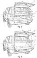
- FIGURE 1 illustrates a vehicle 10 having a split tailgate system 12 according to a nonlimiting embodiment of the invention.
- the split tailgate system 12 may be an electrically driven system configured to articulate an upper tailgate door 14 and a lower tailgate door 16 between open and closed positions.
- FIGURES 2 to 4b illustrate the automatic movement of one or both of the upper and lower tailgate doors 14, 16 between closed and open positions.
- the first, upper, tailgate door 14 may be opened without opening the second, lower, tailgate door 16 (see Figure 2 )
- both of the upper and lower tailgate doors 14, 16 may be opened at the same time (see Figure 3 )
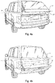
- the lower tailgate door 16 may be opened without opening, or fully opening, the upper tailgate door 14 (see Figures 4a and 4b ).
- a compartment cover 50 may be included with a storage area 52 to extend rearwardly from a rear seat 54 to the tailgate doors 14, 16.
- the compartment cover 50 may be positioned above a bottom 56 of the upper tailgate door 14 when closed and below a top 58 of the rear seat 54 in order to separate the storage area 52 into upper and lower storage portions.
- the coverage of the compartment cover 50 may be adjusted manually by pushing or pulling a leading edge 60, or optionally, with related control of a compartment cover motor 62.
- the bottom portion 56 of the upper tailgate door 14 includes a lock 66 that mates with a latch 68 included on a lip 70 of the lower tailgate door 16.
- a ledge 72 is positioned below the latch 68 to cover the bottom 56 of the upper tailgate door 14 so that an exterior portion 74 of the upper door 14 is flush with an exterior portion 76 of the lower door 16 when both are closed (see Figure 1 ).
- a controller 18 may be included within the vehicle 10 to control tailgate door opening and closing.
- the controller 18 may be configured to independently control movements of the upper and lower tailgate doors 14, 16. This may include an upper mode control sequence shown in Figure 2 where the upper door 14 is actuated to the open position while the lower door 16 remains closed.
- Another door control sequence may be a dual mode shown in Figure 3 where both of the upper and lower doors 14, 16 are simultaneously articulating. Depending on the shape of the doors 14, 16, this may include articulating the upper door 14 slightly ahead of the lower door 16.
- Yet another door control sequence may be a chauffeur mode shown in Figure 4a and Figure 4b where the lower door 16 is actuated while the upper door 14 remains closed, or substantially closed, as will be described in more detail later.
- Wireless messages from a remote control 20, such as but not limited to a fob may be used to instruct the controller 18 to instigate tailgate door control.
- Wireline messages from buttons 24, 26, 28, 30, 32 included within a dashboard 34 or a rear of the vehicle 10 may similarly be used to instruct the controller to open and close one or both of the tailgate doors 14, 16.
- the controller 18 may control operations of an upper electric motor 40 and a lower electric motor 42 in order to respectively control upper and lower tailgate door 14, 16 positioning. While the motors 40, 42 may be positioned anywhere within the vehicle 10, they are shown for exemplary purposes to be disposed within a drain channel 46 around an outer perimeter of the upper tailgate door 14 and within an enclosure of the lower tailgate door 16 that may or may not be watertight, respectively.
- the present invention is able to sequence tailgate door 14, 16 movements in any suitable manner.
- the motors 40, 42 can be controlled so as to open the upper and lower tailgate 14, 16 substantially simultaneously.
- the vehicle may be configured such that the upper tailgate 14 only is opened when a signal is received from the remote control 20 or from an internal button 24, 26 within the vehicle 10 (for example on the dashboard 34) or from an external button 28 provided on the rear of the vehicle 10 (for example on the upper tailgate 14).
- the lower tailgate 16 can only be opened by a user interaction with a lower tailgate button 32 provided at the rear of the vehicle 10.
- the lower tailgate button 32 is mounted upon the lower tailgate 16, and further optionally the lower tailgate button 32 is only accessible once the upper tailgate 14 has been opened or at least partially opened.
- the user may insert or extract items from the storage area 52 via the opening created by opening the upper tailgate 14; this has the advantage that the lower tailgate 14 improves cargo retention, by preventing unintentional egress of the items for example by preventing items rolling out of the storage area 52.
- the lower tailgate 16 may discourage said animals from exiting the storage area 52 in an uncontrolled manner when loading or unloading the animal into or from the vehicle 10; when unloading the animal the user is provided with an opportunity to gain control of the animal whilst still confined within the storage area 52, once under control the user may subsequently open the lower tailgate 14 by pressing the lower tailgate button 32 to facilitate extraction of the animal.
- the user may simultaneously, and remotely (from the tailgate 14, 16), activate closing of both the upper and lower tailgate doors 14, 16 by pressing the same button on the remote control 20 or dashboard 34 of the vehicle 10 which activated the upper only opening mode, or if the lower tailgate 16 is determined to be in a closed position the controller will close the upper tailgate 14.
- Another advantage of the upper tailgate only opening mode is that the user can position themselves closer to the rear of the vehicle 10 when loading or unloading and does not need to stretch over the lower tailgate 14 disposed in the opened condition.
- a further one of the door control sequences or modes of operation may include limiting occupant exposure to the environment (chauffeur mode) by automatically opening only the lower tailgate door 16.
- chauffeur mode occupant exposure to the environment
- the controller 18 is able to automatically open the lower tailgate door 16 in an easier manner and without overly exposing the passenger compartment.
- the upper tailgate door 14 may maintain a position below a horizontal plane P defined by the compartment cover 50 while the lower tailgate door 16 is being opened in order to limit exposure of the upper storage area and the rest of the passenger compartment to the outside elements.
- Figures 4a and 4b illustrate a sequence of door movements that maybe coordinated by the controller 18 when opening the lower tailgate door 16 according to the chauffeur mode sequence of door controls.
- the door controls contemplated by the present invention to manage articulation of the upper and lower tailgate doors 14, 16 may be instigated upon receipt of a message sent from the fob 20 or buttons 24, 26, 28, 30, 32 included on the vehicle 10.
- One of the vehicle buttons 28 may be included on the outside portion 76 of the upper tailgate 14 to control opening and closing of the upper tailgate door 14.
- Another vehicle button 30 having the same functionality of the button 28 may be included on the bottom side 56 of the upper tailgate door 14 to provide easy button access when the upper tailgate door 14 is open.
- Another button 32 to control open and closing of the lower tailgate door 16 may be included on the ledge 72 such that it is concealed from view when the upper door 14 is closed, which may be helpful in providing a more uniform rearward appearance for the vehicle 10 than including the button on the exterior portion 74 of the lower tailgate door 16.
- buttons 24 may be an upper door button included on the dashboard 34 that instructs the controller 18 to open or close the upper tailgate door 14.
- This button 24 may be 'fixed' in that is pre-programmed to control the upper tailgate door 14 at the time of manufacturing.
- Another button 26 included in the dashboard 34 may be a "programmable" button in that it can be programmed by a vehicle occupant to selectively execute an available door control.
- a programming selection menu having a number of available door control sequences may be displayed within a display or other human machine interface (HMI) 80 such that user selection of one of the door control sequences controls whether the button 26 controls both doors 14, 16 (dual mode), only the lower door 16 (chauffeur mode), or some other operation, such as but not limited to vehicle illumination, e.g., the interior/exterior of the vehicle 10, including the doors 14, 16, may be illuminated.
- the illumination mode may be "fixed" in vehicles having a single tailgate door or split tailgate doors where the lower tailgate door 16 is powered.
- Buttons 84, 86 included on the fob 20 may mimic the functionality provided by the buttons 24, 26 included within the dashboard 34.
- the fob 20 may include the same "fixed" assignment of an upper door button 84 and the same "programmable” assignment of a programmable button 86.
- the fob 20 may also include buttons 88, 90, 92 to instruct the controller 18 to execute the vehicle controls, such as but not limited to a door unlock button 90, door lock button 88, and panic button 92, which are commonly employed with remote keyless entry (RKE) related systems.
- RKE remote keyless entry
- the fob 20 may also perform other operations, such as but not limited to passive entry (PE), including passively supporting tailgate door control sequences.
- PE passive entry
- Depression of the fob buttons 84, 86, 88, 90, 92 may instruct the fob 20 to issue a specific message depending on the depressed button.
- the message transmitted from the programmable key 86 may be the same regardless of the operation to be controlled by the controller 18 in response to receipt of the message.
- the remote control 20 and the dashboard 34 may each comprise a single button for activation of the tailgate door system 12.
- the single button on each of the remote control 20 and the dashboard 34 may be a 'fixed' button for example for carrying out the upper only control mode sequence of operations or a 'programmable' button. It is envisaged that the function performed by the single button on remote control 20 would be the same as the function performed by the single button on the dashboard 34, though the functions could be different in yet other embodiments.
- each fob 20 may be configured to issue the same message upon actuation of the same fob button 84, 86, 88, 90, 92. In this manner, the controller 18 need not interpret the messages differently depending on the fob 20 transmitting the message or throughout changes in programming of the programmable button 86.
- the controller 18 can use the identifiers to lookup an associated user in order to execute user specific operations. In this manner, a first user can program the controller 18 to execute a different tailgate door control sequence than a second user associated with another fob 20 even though both fobs 20 transmit the same message upon actuation of the programmable button 86.
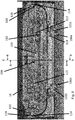
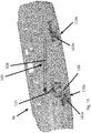
- FIGs 5 to 15 illustrate an actuator mechanism 100 provided within the lower tailgate 16 of a vehicle 10.
- the lower tailgate 16 is illustrated in Figures 5 to 15 although it will be appreciated that the mechanism 100 could be mounted within an upper tailgate 14 or other door in alternative embodiments.
- the lower tailgate 16 is shown in Figure 5 from a position external of the vehicle 10.
- the lower tailgate 16 comprises a pair of hinges 116a, 116b; in other embodiments the lower tailgate 16 may comprise more or fewer hinges.
- the hinges 116a, 116b are fixedly mounted to the vehicle 10.
- the lower tailgate 16 is pivotally mounted to the vehicle 10 by the pair of hinges 116a, 116b and rotates about a pivot axis 123, shown as a phantom line.
- the hinges 116a, 116b comprise first part 101a, 101b mounted to the lower tailgate 16 and a second part 102a, 102b mounted to the vehicle 10; the first and second parts 101a, 101b, 102a, 102b being pivotally coupled 117 to one another.
- the pivotal couple 117 of the hinges 116a, 116b is disposed within the interior of the lower tailgate 16.
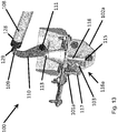
- the actuator mechanism 100 comprises an actuator 108; the actuator 108 is pivotally coupled to the lower tailgate 16 at a first end 122 and is pivotally coupled to a bell crank 110 at a second end 128.
- the bell crank 110 is pivotally mounted to the lower tailgate 16 by a pivot point 111.
- the bell crank 110 is coupled to one of the pair of hinges 116a by a drop link 118; the drop link 118 is pivotally coupled to the bell crank 110 at one end and is pivotally coupled to the hinge 116a at an opposing end.
- the drop link 118 may be coupled to a bracket 103 which is mounted the second part 102a of the hinge 116a.
- the drop link 118 may be directly coupled to the second part 102a of the hinge 116a upon which the ball joint may be integrated.
- each of the pivotal connections, between the actuator 108 and the lower tailgate 16; between the actuator 108 and the bell crank 110; between the bell crank 110 and the drop link 118; and between the drop link 118 and the hinge 116a will comprise a ball and socket joint.
- a ball is provided on the hinge 116a and on each of the bell crank connections 109, 113 and on the lower tailgate 16.
- a socket is provided at each end of the drop link 118 and at each end of the actuator 108.
- other suitable connection devices may be provided which allow rotational or pivotal movement for example, but not limited to, a hinge.
- the actuator 108 comprises a first, inner, tube telescopically mounted within a second, outer, tube.
- Drive means in the form of a motor (not shown), is mounted within the first tube; a spindle (not shown) is coupled to a drive shaft of the motor via a gear system, such that the motor can rotate the spindle about a longitudinal axis.
- the spindle comprises a helical thread disposed on an outer surface; the second tube comprises a corresponding helical thread disposed on an inner surface of the tube.
- a nut comprising an internal thread is mounted within the second tube and is mounted upon the external thread of the spindle.
- the actuator 108 is electrically powered from the vehicle 10 and the length of the actuator 108 can be changed by driving the motor (not shown). Driving the motor causes the spindle to rotate which in turns causes the nut and/or second tube to travel axially along the spindle as indicated by direction arrow D1; in this way the length of the actuator 108 may be increased or decreased.
- the actuator 108 comprises an electrical connection (not shown), for example an electrical power cable; optionally the electrical connection is provided at an end of the actuator 108, adjacent to, or closest to, the motor, in some embodiments this is arranged to be the first end 122 (the end furthest from the bell crank 110) of the actuator 108; this is beneficial since this limits the articulation the electrical power cable must go through when the actuator 108 is being operated.
- an electrical connection for example an electrical power cable
- the electrical connection is provided at an end of the actuator 108, adjacent to, or closest to, the motor, in some embodiments this is arranged to be the first end 122 (the end furthest from the bell crank 110) of the actuator 108; this is beneficial since this limits the articulation the electrical power cable must go through when the actuator 108 is being operated.
- Changing the length of the actuator 108 causes the bell crank 110 to rotate as indicated by direction arrow D3.
- the rotation of the bell crank 110 causes the drop link 118 to move in a direction, as indicated by direction arrow D2, which direction is disposed at an angle with respect to the direction of travel of the second tube of the actuator 108 indicated by direction arrow D1.
- the pivotal connection 115 between the drop link 118 and hinge 116a is offset, by a distance O from the pivotal coupling between the hinge 116a and the lower tailgate 16 such that movement of the drop link 118 effects a rotation of the lower tailgate 16.
- changing the length of the actuator 108 brings about a rotation of the lower tailgate 16 as indicated by direction arrow D4.
- the movement of the actuator 108 can be calibrated to move the lower tailgate 16 between the closed position, in which the tailgate 16 is substantially vertical, as shown in Figures 1 , 2 and 4a , and the open position in which the tailgate 16 is substantially horizontal, as shown in Figures 3 and 4b .
- the pivot point 115 between the drop link 118 and hinge 116a defines a pivot axis 124 parallel to the pivot axis 123 of the hinges 116a, 116b, and offset therefrom by the distance O.
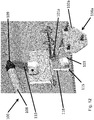
- Figures 6 to 9 illustrate the actuator mechanism 100 packaged within a cavity or void of the lower tailgate 16, such that the actuator 108 is concealed from view.
- the actuator 108 is thereby protected by the lower tailgate 16 so as to reduce the risk of damage when loading and unloading items into the vehicle 10.
- the arrangement maximises the accessibility of the storage space 52 of the vehicle since the actuator mechanism 100 is contained within, that is to say it does not extend outwardly from, the lower tailgate 16.
- the lower tailgate 16 may comprise a pair of actuator mechanisms 100; one actuator mechanism 100 coupled to each of the hinges 116a, 116b; in yet other embodiments an actuator mechanism 100 may be provided for each hinge coupling the lower tailgate 16 to the vehicle 10.
- the lower tailgate 16 comprises a pair of cable stays 119, the cable stays 119 are provided at each side of the lower tailgate 16.
- the cable stays 119 comprise a cable 114 which passes through an aperture in the lower tailgate 16.
- the cable stays 119 are coupled to mounting locations 120 on the vehicle 10 which are disposed on opposing sides of the opening defined by the upper and lower tailgates 14, 16.
- the cable stays 119 are retractable into a housing 112 which is mounted within the cavity defined by the lower tailgate 16.
- the cable stays 119 provide support to the lower tailgate 16 when disposed in the open position, such that if a load is placed upon the lower tailgate 16 when in the open position the cable stays 119 bear at least some of the load applied, the remainder of the load may be borne by the hinges 116a, 116b. In this way the cable stays 119 prevent over rotation or opening of the lower tailgate 16.
- the cable stays 119 comprise a retraction device (not shown) such as a coil spring mounted within the housing 112, these coil springs provide a counterbalancing force which is substantially sufficient that the tailgate 16 may be held in equilibrium through the range of motion of the lower tailgate 16; that is to say the lower tailgate 16 may remain stationary if the motor is stopped from driving the actuator at positions between the fully closed position and the fully opened position; some angles of the lower tailgate 16, or inclinations of the vehicle 10 the lower tailgate 16 may have a self-opening or self-closing tendency.
- the retraction mechanism may be sufficient to hold the lower tailgate 16 stationary at any position of its travel.
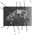
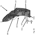
- Figures 10 to 15 illustrate the actuating mechanism 100 of the lower tailgate door 16 in isolation with other components of the door omitted for clarity.
- the offset O between the pivot axis 123 of the first hinge 116a and the pivot axis 124 defined by the coupling between the drop link 118 (not visible in Figure 15 ) and the bracket 103 ensures that the force applied by the actuating mechanism 100 to the vehicle 10 acts about a point which is spaced apart from the pivot axis 124 of the hinges 116a, 116b.
- This offset provides the necessary mechanical leverage for the actuating mechanism to be able to open and close the lower tailgate door 16.
- the drop link 118 transmits the force of the actuator 108 to the vehicle 10 via the bracket 103 which, in turn, is fixed to the second part 112a of the first hinge 116a
- the drop link 118 could be pivotally attached to another suitable support structure provided on the vehicle.
- a dedicated bracket, separate from either of the hinges 116a, 116b could be provided at a point between the respective hinges 116a, 116b.
- the bell crank 15 and drop link 118 may be omitted and the actuator 108 may be mounted directly an end of the hinge 116a which is disposed within the cavity defined by the lower tailgate 16, in such embodiments it will be appreciated that the orientation of the actuator 108, and/or the location of its connection to the tailgate may be adjusted so as to achieve the rotational movement of the lower tailgate 16, for example the actuator may be orientated and positioned in a location similar to that of the drop link 118.
- the cable stay may comprise an alternative suspension structure for example the cable may be replaced with, but not limited to, a chain, rope or cord, webbing, belt or strap.
- the actuator 108 may comprise a piston and cylinder which are hydraulically or pneumatically operated, the drive means may comprise a pump for driving the piston.
Landscapes
- Engineering & Computer Science (AREA)
- Mechanical Engineering (AREA)
- Power-Operated Mechanisms For Wings (AREA)
Applications Claiming Priority (3)
| Application Number | Priority Date | Filing Date | Title |
|---|---|---|---|
| GBGB1215962.0A GB201215962D0 (en) | 2012-09-06 | 2012-09-06 | Power tailgate system and method |
| GB1307884.5A GB2505739B (en) | 2012-09-06 | 2013-05-01 | Power tailgate system |
| PCT/EP2013/068410 WO2014037468A1 (en) | 2012-09-06 | 2013-09-05 | Power tailgate system and method |
Publications (2)
| Publication Number | Publication Date |
|---|---|
| EP2892745A1 EP2892745A1 (en) | 2015-07-15 |
| EP2892745B1 true EP2892745B1 (en) | 2018-08-01 |
Family
ID=47137078
Family Applications (1)
| Application Number | Title | Priority Date | Filing Date |
|---|---|---|---|
| EP13759499.0A Active EP2892745B1 (en) | 2012-09-06 | 2013-09-05 | Power tailgate system and method |
Country Status (6)
| Country | Link |
|---|---|
| US (1) | US9636978B2 (enExample) |
| EP (1) | EP2892745B1 (enExample) |
| JP (1) | JP6203264B2 (enExample) |
| CN (1) | CN104703825B (enExample) |
| GB (2) | GB201215962D0 (enExample) |
| WO (1) | WO2014037468A1 (enExample) |
Families Citing this family (32)
| Publication number | Priority date | Publication date | Assignee | Title |
|---|---|---|---|---|
| US9890576B2 (en) * | 2015-07-29 | 2018-02-13 | Ford Global Technologies, Llc | Active door operation based on voice commands |
| US9818246B2 (en) * | 2015-07-29 | 2017-11-14 | Ford Global Technologies, Llc | System and method for gesture-based control of a vehicle door |
| US10113351B2 (en) * | 2015-10-26 | 2018-10-30 | Ford Global Technologies, Llc | Intelligent vehicle access point opening system |
| DE102016103759A1 (de) | 2016-03-02 | 2017-09-07 | Brose Fahrzeugteile Gmbh & Co. Kg, Bamberg | Antriebsanordnung für eine Klappe eines Kraftfahrzeugs |
| US10286873B1 (en) * | 2016-03-23 | 2019-05-14 | Kevin Krush | Tailgate lock controller |
| DE102016210168B3 (de) | 2016-06-09 | 2017-04-13 | Bayerische Motoren Werke Aktiengesellschaft | Türantrieb für eine Kraftwagentür |
| CN106864225A (zh) * | 2017-03-10 | 2017-06-20 | 金翌宇锋车业有限公司 | 电动四轮车后组合门 |
| DE102017107839A1 (de) * | 2017-04-11 | 2018-10-11 | Brose Fahrzeugteile Gmbh & Co. Kg, Bamberg | Reibschlussanordnung für einen Antrieb eines Verschlusselements eines Kraftfahrzeugs |
| CN110271395B (zh) * | 2018-03-15 | 2023-10-31 | 蔚来控股有限公司 | 尾门总成和车辆 |
| DE102018111067A1 (de) * | 2018-05-08 | 2019-11-14 | Brose Fahrzeugteile Gmbh & Co. Kommanditgesellschaft, Bamberg | Antriebsanordnung für eine Klappe eines Kraftfahrzeugs |
| US10723275B2 (en) * | 2018-09-28 | 2020-07-28 | Ford Global Technologies, Llc | Secure access to storage devices within vehicle cargo compartments |
| US11098518B2 (en) | 2018-12-13 | 2021-08-24 | Fca Us Llc | Power tailgate motor mount cartridge assembly |
| CN112172480B (zh) * | 2019-07-04 | 2022-04-08 | 南京航空航天大学 | 一种客车安全逃生系统 |
| US10850707B1 (en) | 2019-11-19 | 2020-12-01 | Honda Motor Co., Ltd. | Tailgate locking system and method of operating |
| JP7234966B2 (ja) * | 2020-02-13 | 2023-03-08 | トヨタ自動車株式会社 | 降車支援装置 |
| JP7236025B2 (ja) * | 2020-02-18 | 2023-03-09 | マルティマティック インコーポレイティッド | 一体化された折り畳み可能なドアを有する車両用テールゲート |
| US11872927B2 (en) | 2020-05-15 | 2024-01-16 | Toyota Motor Engineering & Manufacturing North America, Inc. | Tail lamp back door/tailgate activation switch |
| US11906348B2 (en) | 2021-01-26 | 2024-02-20 | Ford Global Technologies, Llc | Load-sensing closure panel |
| US11440462B1 (en) | 2021-03-10 | 2022-09-13 | Ford Global Technologies, Llc | Liftgate lighting system |
| US11988032B2 (en) | 2021-03-11 | 2024-05-21 | Ford Global Technologies, Llc | Vehicle door control system |
| US12097794B2 (en) | 2021-03-11 | 2024-09-24 | Ford Global Technologies, Llc | Load ramp for a vehicle |
| US11708062B2 (en) | 2021-04-05 | 2023-07-25 | Ford Global Technologies, Llc | Controlling vehicle components to adjust passenger compartment airflow |
| US12220974B2 (en) | 2021-04-13 | 2025-02-11 | Ford Global Technologies, Llc | System for controlling a closure panel of a vehicle |
| US12370872B2 (en) | 2021-04-13 | 2025-07-29 | Ford Global Technologies, Llc | System for a vehicle operable to enter a reverse mode |
| US11878654B2 (en) | 2021-04-13 | 2024-01-23 | Ford Global Technologies, Llc | System for sensing a living being proximate to a vehicle |
| US11247635B1 (en) | 2021-04-13 | 2022-02-15 | Ford Global Technologies, Llc | System for providing access to a vehicle |
| US12090824B2 (en) | 2021-04-13 | 2024-09-17 | Ford Global Technologies, Llc | System for a vehicle with a trailer coupled thereto |
| US11926200B2 (en) | 2021-05-21 | 2024-03-12 | Ford Global Technologies, Llc | Rear closure assembly for vehicle including liftgate and tailgate moveable by common actuator |
| KR20230004004A (ko) * | 2021-06-30 | 2023-01-06 | 삼성전자주식회사 | 전기 장치 및 그 제어 방법 |
| EP4163465A1 (en) * | 2021-10-07 | 2023-04-12 | Volvo Car Corporation | Apparatus for moving a lower lid of a split tailgate in a car |
| CN115110878B (zh) * | 2022-06-29 | 2023-06-20 | 重庆长安汽车股份有限公司 | 一种背门结构、汽车及背门开启方法 |
| US20250115100A1 (en) * | 2023-10-10 | 2025-04-10 | Rivian Ip Holdings, Llc | Operating dual closures utilizing a common system |
Family Cites Families (38)
| Publication number | Priority date | Publication date | Assignee | Title |
|---|---|---|---|---|
| US2793907A (en) * | 1954-07-14 | 1957-05-28 | Gen Motors Corp | Vertically swingable station-wagon tail-gate with retractible window |
| US2999683A (en) * | 1958-12-23 | 1961-09-12 | Ferro Stamping Co | Automatic luggage compartment lid control system |
| US3069151A (en) * | 1959-06-18 | 1962-12-18 | Dura Corp | Power actuated door operator |
| US3022108A (en) * | 1960-06-17 | 1962-02-20 | Gen Motors Corp | Power-actuated tail gate |
| US3202414A (en) * | 1962-01-15 | 1965-08-24 | Gen Motors Corp | Vehicle door actuator |
| US3306655A (en) * | 1964-06-17 | 1967-02-28 | Gen Motors Corp | Vehicle tailgate actuator |
| US3274732A (en) * | 1964-08-24 | 1966-09-27 | Murakami Paul | Car door actuator device |
| US3398484A (en) * | 1965-06-04 | 1968-08-27 | Katsumura Toru | Car door actuator |
| JP3814939B2 (ja) * | 1997-05-14 | 2006-08-30 | トヨタ車体株式会社 | 車両用ゲートの開閉支持装置 |
| KR100260405B1 (ko) * | 1997-11-29 | 2000-08-01 | 정몽규 | 차량의트윈스윙테일게이트오동작방지장치 |
| US5896703A (en) * | 1998-06-26 | 1999-04-27 | General Motors Corporation | Power liftgate cable drive |
| US6092336A (en) * | 1999-02-11 | 2000-07-25 | Delphi Technologies, Inc. | Power liftgate cable drive with position stop |
| FR2789644B1 (fr) * | 1999-02-12 | 2001-04-13 | Plastic Omnium Cie | Ouvrant arriere de vehicule automobile, monte pivotant autour d'un axe horizontal au voisinage de son bord inferieur |
| US6676190B2 (en) * | 2000-04-27 | 2004-01-13 | Atoma International Corp. | Headliner mounted power liftgate drive mechanism |
| US6814392B1 (en) * | 2000-06-26 | 2004-11-09 | Atoma International Corp. | Lead screw drive for a power liftgate |
| US6305737B1 (en) * | 2000-08-02 | 2001-10-23 | Asc Incorporated | Automotive vehicle door system |
| DE10202313A1 (de) * | 2001-11-13 | 2003-05-28 | Stabilus Gmbh | Schließeinrichtung, insbesondere für ein Kfz |
| EP1468160A1 (en) * | 2002-01-24 | 2004-10-20 | Intier Automotive Closures Inc. | Power lift gate actuator |
| WO2003067010A1 (en) * | 2002-02-08 | 2003-08-14 | Multimatic Inc. | Lift assist mechanism for vehicle tailgates |
| JP3990611B2 (ja) * | 2002-08-22 | 2007-10-17 | 本田技研工業株式会社 | 車両の後部ドア構造 |
| JP4036074B2 (ja) * | 2002-10-25 | 2008-01-23 | アイシン精機株式会社 | 車両ドア駆動装置 |
| JP4249656B2 (ja) * | 2004-05-20 | 2009-04-02 | 株式会社城南製作所 | ドア開閉装置 |
| US20080066385A1 (en) * | 2004-12-10 | 2008-03-20 | Roach Jack R | Vehicle tailgate dampener and lift assist system |
| CN2774835Y (zh) * | 2005-02-25 | 2006-04-26 | 王韵棠 | 机动车用双开启后门 |
| US7147260B2 (en) * | 2005-03-11 | 2006-12-12 | Nissan Technical Center North America | Vehicle tailgate lift assist support structure |
| US7281748B2 (en) * | 2005-04-11 | 2007-10-16 | Dura Global Technologies, Inc. | Tailgate lift-and-secure cable and latch assembly |
| US7695043B2 (en) * | 2005-07-21 | 2010-04-13 | Zagoroff Dimiter S | Truck tailgate with motion control devices |
| US20070152471A1 (en) * | 2005-07-21 | 2007-07-05 | Zagoroff Dimiter S | Truck tailgate with internal motion control devices |
| GB0602724D0 (en) * | 2006-02-10 | 2006-03-22 | Ford Global Tech Llc | A Mechanism For Opening A Closure |
| US7556303B2 (en) * | 2006-04-07 | 2009-07-07 | Magna International Inc. | Lift gate latch transfer mechanism |
| US7484784B2 (en) * | 2006-08-31 | 2009-02-03 | Nissan Technical Center North America, Inc. | Selectively removable tailgate hinge for a power tailgate |
| US7547055B2 (en) * | 2007-02-20 | 2009-06-16 | Ford Global Technologies, Llc | Vehicle tailgate movement assist mechanism using four bar linkage and strut |
| US7556305B2 (en) * | 2007-02-20 | 2009-07-07 | Ford Global Technologies, Llc | Vehicle tailgate movement assist mechanism using cam |
| US7654600B2 (en) * | 2007-02-20 | 2010-02-02 | Ford Global Technologies, Llc | Vehicle tailgate movement assist mechanism using lever driven rotary damper |
| US7500711B1 (en) * | 2007-08-24 | 2009-03-10 | Ford Global Technologies, Llc | Power door for a passenger vehicle |
| JP4366665B1 (ja) * | 2008-08-28 | 2009-11-18 | 株式会社ジョウヨウ | ドア開閉機構 |
| DE202009002622U1 (de) * | 2009-02-25 | 2010-07-22 | Brose Fahrzeugteile Gmbh & Co. Kommanditgesellschaft, Hallstadt | Antriebsanordnung zur Betätigung einer Klappe eines Kraftfahrzeugs |
| US8174146B2 (en) * | 2009-04-16 | 2012-05-08 | Land Rover | Power split tailgate system and method |
-
2012
- 2012-09-06 GB GBGB1215962.0A patent/GB201215962D0/en not_active Ceased
-
2013
- 2013-05-01 GB GB1307884.5A patent/GB2505739B/en active Active
- 2013-09-05 WO PCT/EP2013/068410 patent/WO2014037468A1/en not_active Ceased
- 2013-09-05 JP JP2015530395A patent/JP6203264B2/ja active Active
- 2013-09-05 CN CN201380052730.XA patent/CN104703825B/zh active Active
- 2013-09-05 EP EP13759499.0A patent/EP2892745B1/en active Active
- 2013-09-05 US US14/426,219 patent/US9636978B2/en active Active
Also Published As
| Publication number | Publication date |
|---|---|
| GB201215962D0 (en) | 2012-10-24 |
| CN104703825B (zh) | 2017-11-24 |
| US20150217631A1 (en) | 2015-08-06 |
| EP2892745A1 (en) | 2015-07-15 |
| JP6203264B2 (ja) | 2017-09-27 |
| GB201307884D0 (en) | 2013-06-12 |
| JP2015532623A (ja) | 2015-11-12 |
| WO2014037468A1 (en) | 2014-03-13 |
| GB2505739A (en) | 2014-03-12 |
| US9636978B2 (en) | 2017-05-02 |
| GB2505739B (en) | 2016-05-25 |
| CN104703825A (zh) | 2015-06-10 |
Similar Documents
| Publication | Publication Date | Title |
|---|---|---|
| EP2892745B1 (en) | Power tailgate system and method | |
| US8366175B2 (en) | Door checker drive mechanism | |
| EP2419289B1 (en) | Power split tailgate system and method | |
| EP3142877B1 (en) | Articulated gull wing door | |
| US9879465B2 (en) | Programmable door power assist | |
| EP1154113A2 (en) | Vehicle pivoting closure power operating assembly | |
| US11794820B2 (en) | Latching mechanism for a closure panel using multiple latches | |
| US12296783B2 (en) | Actuation system for a closure panel including a pop up safety system for hinges | |
| CN102561878A (zh) | 用于在具有进入口的车辆中促动多个部件的系统和方法 | |
| EP2578426B1 (en) | Vehicle with openable closure | |
| EP1246989A1 (en) | Drive arrangement for a power liftgate including a clutching mechanism | |
| US20030080632A1 (en) | Linear actuator for a powered vehicle lift gate | |
| CN102839886B (zh) | 车辆中整体式动力尾板和擦拭器促动 | |
| US20120326466A1 (en) | Actuation of a power operated tailgate | |
| US20110314744A1 (en) | Locking controller structure of sliding door | |
| US8845006B2 (en) | Power liftgate in a vehicle | |
| JP4905739B2 (ja) | 自動車のドア装置 | |
| US20170275931A1 (en) | Lock system for dual vehicle closures | |
| EP3342610B1 (en) | Tailgate for a vehicle | |
| KR101739188B1 (ko) | 탈부착 가능한 차량트렁크 자동개폐장치 | |
| CN104709038B (zh) | 用于闩锁车辆折叠式车顶的机构 |
Legal Events
| Date | Code | Title | Description |
|---|---|---|---|
| PUAI | Public reference made under article 153(3) epc to a published international application that has entered the european phase |
Free format text: ORIGINAL CODE: 0009012 |
|
| 17P | Request for examination filed |
Effective date: 20150407 |
|
| AK | Designated contracting states |
Kind code of ref document: A1 Designated state(s): AL AT BE BG CH CY CZ DE DK EE ES FI FR GB GR HR HU IE IS IT LI LT LU LV MC MK MT NL NO PL PT RO RS SE SI SK SM TR |
|
| AX | Request for extension of the european patent |
Extension state: BA ME |
|
| DAX | Request for extension of the european patent (deleted) | ||
| RIC1 | Information provided on ipc code assigned before grant |
Ipc: E05F 15/63 20150101ALI20170921BHEP Ipc: E05F 15/622 20150101ALI20170921BHEP Ipc: B60J 5/10 20060101AFI20170921BHEP |
|
| GRAP | Despatch of communication of intention to grant a patent |
Free format text: ORIGINAL CODE: EPIDOSNIGR1 |
|
| INTG | Intention to grant announced |
Effective date: 20171110 |
|
| RAP1 | Party data changed (applicant data changed or rights of an application transferred) |
Owner name: JAGUAR LAND ROVER LIMITED |
|
| GRAJ | Information related to disapproval of communication of intention to grant by the applicant or resumption of examination proceedings by the epo deleted |
Free format text: ORIGINAL CODE: EPIDOSDIGR1 |
|
| GRAP | Despatch of communication of intention to grant a patent |
Free format text: ORIGINAL CODE: EPIDOSNIGR1 |
|
| INTC | Intention to grant announced (deleted) | ||
| INTG | Intention to grant announced |
Effective date: 20180219 |
|
| GRAS | Grant fee paid |
Free format text: ORIGINAL CODE: EPIDOSNIGR3 |
|
| GRAA | (expected) grant |
Free format text: ORIGINAL CODE: 0009210 |
|
| RBV | Designated contracting states (corrected) |
Designated state(s): AL AT BE BG CH CY CZ DE DK EE ES FI FR GR HR HU IE IS IT LI LT LU LV MC MK MT NL NO PL PT RO RS SE SI SK SM TR |
|
| AK | Designated contracting states |
Kind code of ref document: B1 Designated state(s): AL AT BE BG CH CY CZ DE DK EE ES FI FR GR HR HU IE IS IT LI LT LU LV MC MK MT NL NO PL PT RO RS SE SI SK SM TR |
|
| REG | Reference to a national code |
Ref country code: CH Ref legal event code: EP Ref country code: AT Ref legal event code: REF Ref document number: 1023876 Country of ref document: AT Kind code of ref document: T Effective date: 20180815 |
|
| REG | Reference to a national code |
Ref country code: IE Ref legal event code: FG4D |
|
| REG | Reference to a national code |
Ref country code: DE Ref legal event code: R096 Ref document number: 602013041225 Country of ref document: DE |
|
| REG | Reference to a national code |
Ref country code: FR Ref legal event code: PLFP Year of fee payment: 6 |
|
| REG | Reference to a national code |
Ref country code: NL Ref legal event code: MP Effective date: 20180801 |
|
| REG | Reference to a national code |
Ref country code: LT Ref legal event code: MG4D |
|
| REG | Reference to a national code |
Ref country code: AT Ref legal event code: MK05 Ref document number: 1023876 Country of ref document: AT Kind code of ref document: T Effective date: 20180801 |
|
| PG25 | Lapsed in a contracting state [announced via postgrant information from national office to epo] |
Ref country code: LT Free format text: LAPSE BECAUSE OF FAILURE TO SUBMIT A TRANSLATION OF THE DESCRIPTION OR TO PAY THE FEE WITHIN THE PRESCRIBED TIME-LIMIT Effective date: 20180801 Ref country code: IS Free format text: LAPSE BECAUSE OF FAILURE TO SUBMIT A TRANSLATION OF THE DESCRIPTION OR TO PAY THE FEE WITHIN THE PRESCRIBED TIME-LIMIT Effective date: 20181201 Ref country code: PL Free format text: LAPSE BECAUSE OF FAILURE TO SUBMIT A TRANSLATION OF THE DESCRIPTION OR TO PAY THE FEE WITHIN THE PRESCRIBED TIME-LIMIT Effective date: 20180801 Ref country code: FI Free format text: LAPSE BECAUSE OF FAILURE TO SUBMIT A TRANSLATION OF THE DESCRIPTION OR TO PAY THE FEE WITHIN THE PRESCRIBED TIME-LIMIT Effective date: 20180801 Ref country code: RS Free format text: LAPSE BECAUSE OF FAILURE TO SUBMIT A TRANSLATION OF THE DESCRIPTION OR TO PAY THE FEE WITHIN THE PRESCRIBED TIME-LIMIT Effective date: 20180801 Ref country code: NO Free format text: LAPSE BECAUSE OF FAILURE TO SUBMIT A TRANSLATION OF THE DESCRIPTION OR TO PAY THE FEE WITHIN THE PRESCRIBED TIME-LIMIT Effective date: 20181101 Ref country code: BG Free format text: LAPSE BECAUSE OF FAILURE TO SUBMIT A TRANSLATION OF THE DESCRIPTION OR TO PAY THE FEE WITHIN THE PRESCRIBED TIME-LIMIT Effective date: 20181101 Ref country code: AT Free format text: LAPSE BECAUSE OF FAILURE TO SUBMIT A TRANSLATION OF THE DESCRIPTION OR TO PAY THE FEE WITHIN THE PRESCRIBED TIME-LIMIT Effective date: 20180801 Ref country code: NL Free format text: LAPSE BECAUSE OF FAILURE TO SUBMIT A TRANSLATION OF THE DESCRIPTION OR TO PAY THE FEE WITHIN THE PRESCRIBED TIME-LIMIT Effective date: 20180801 Ref country code: GR Free format text: LAPSE BECAUSE OF FAILURE TO SUBMIT A TRANSLATION OF THE DESCRIPTION OR TO PAY THE FEE WITHIN THE PRESCRIBED TIME-LIMIT Effective date: 20181102 Ref country code: SE Free format text: LAPSE BECAUSE OF FAILURE TO SUBMIT A TRANSLATION OF THE DESCRIPTION OR TO PAY THE FEE WITHIN THE PRESCRIBED TIME-LIMIT Effective date: 20180801 |
|
| PG25 | Lapsed in a contracting state [announced via postgrant information from national office to epo] |
Ref country code: HR Free format text: LAPSE BECAUSE OF FAILURE TO SUBMIT A TRANSLATION OF THE DESCRIPTION OR TO PAY THE FEE WITHIN THE PRESCRIBED TIME-LIMIT Effective date: 20180801 Ref country code: LV Free format text: LAPSE BECAUSE OF FAILURE TO SUBMIT A TRANSLATION OF THE DESCRIPTION OR TO PAY THE FEE WITHIN THE PRESCRIBED TIME-LIMIT Effective date: 20180801 Ref country code: AL Free format text: LAPSE BECAUSE OF FAILURE TO SUBMIT A TRANSLATION OF THE DESCRIPTION OR TO PAY THE FEE WITHIN THE PRESCRIBED TIME-LIMIT Effective date: 20180801 |
|
| PG25 | Lapsed in a contracting state [announced via postgrant information from national office to epo] |
Ref country code: CZ Free format text: LAPSE BECAUSE OF FAILURE TO SUBMIT A TRANSLATION OF THE DESCRIPTION OR TO PAY THE FEE WITHIN THE PRESCRIBED TIME-LIMIT Effective date: 20180801 Ref country code: IT Free format text: LAPSE BECAUSE OF FAILURE TO SUBMIT A TRANSLATION OF THE DESCRIPTION OR TO PAY THE FEE WITHIN THE PRESCRIBED TIME-LIMIT Effective date: 20180801 Ref country code: MC Free format text: LAPSE BECAUSE OF FAILURE TO SUBMIT A TRANSLATION OF THE DESCRIPTION OR TO PAY THE FEE WITHIN THE PRESCRIBED TIME-LIMIT Effective date: 20180801 Ref country code: EE Free format text: LAPSE BECAUSE OF FAILURE TO SUBMIT A TRANSLATION OF THE DESCRIPTION OR TO PAY THE FEE WITHIN THE PRESCRIBED TIME-LIMIT Effective date: 20180801 Ref country code: ES Free format text: LAPSE BECAUSE OF FAILURE TO SUBMIT A TRANSLATION OF THE DESCRIPTION OR TO PAY THE FEE WITHIN THE PRESCRIBED TIME-LIMIT Effective date: 20180801 Ref country code: RO Free format text: LAPSE BECAUSE OF FAILURE TO SUBMIT A TRANSLATION OF THE DESCRIPTION OR TO PAY THE FEE WITHIN THE PRESCRIBED TIME-LIMIT Effective date: 20180801 |
|
| REG | Reference to a national code |
Ref country code: CH Ref legal event code: PL |
|
| REG | Reference to a national code |
Ref country code: DE Ref legal event code: R097 Ref document number: 602013041225 Country of ref document: DE |
|
| PG25 | Lapsed in a contracting state [announced via postgrant information from national office to epo] |
Ref country code: SM Free format text: LAPSE BECAUSE OF FAILURE TO SUBMIT A TRANSLATION OF THE DESCRIPTION OR TO PAY THE FEE WITHIN THE PRESCRIBED TIME-LIMIT Effective date: 20180801 Ref country code: DK Free format text: LAPSE BECAUSE OF FAILURE TO SUBMIT A TRANSLATION OF THE DESCRIPTION OR TO PAY THE FEE WITHIN THE PRESCRIBED TIME-LIMIT Effective date: 20180801 Ref country code: SK Free format text: LAPSE BECAUSE OF FAILURE TO SUBMIT A TRANSLATION OF THE DESCRIPTION OR TO PAY THE FEE WITHIN THE PRESCRIBED TIME-LIMIT Effective date: 20180801 |
|
| PLBE | No opposition filed within time limit |
Free format text: ORIGINAL CODE: 0009261 |
|
| STAA | Information on the status of an ep patent application or granted ep patent |
Free format text: STATUS: NO OPPOSITION FILED WITHIN TIME LIMIT |
|
| REG | Reference to a national code |
Ref country code: BE Ref legal event code: MM Effective date: 20180930 |
|
| REG | Reference to a national code |
Ref country code: IE Ref legal event code: MM4A |
|
| PG25 | Lapsed in a contracting state [announced via postgrant information from national office to epo] |
Ref country code: LU Free format text: LAPSE BECAUSE OF NON-PAYMENT OF DUE FEES Effective date: 20180905 |
|
| 26N | No opposition filed |
Effective date: 20190503 |
|
| PG25 | Lapsed in a contracting state [announced via postgrant information from national office to epo] |
Ref country code: IE Free format text: LAPSE BECAUSE OF NON-PAYMENT OF DUE FEES Effective date: 20180905 |
|
| PG25 | Lapsed in a contracting state [announced via postgrant information from national office to epo] |
Ref country code: BE Free format text: LAPSE BECAUSE OF NON-PAYMENT OF DUE FEES Effective date: 20180930 Ref country code: LI Free format text: LAPSE BECAUSE OF NON-PAYMENT OF DUE FEES Effective date: 20180930 Ref country code: SI Free format text: LAPSE BECAUSE OF FAILURE TO SUBMIT A TRANSLATION OF THE DESCRIPTION OR TO PAY THE FEE WITHIN THE PRESCRIBED TIME-LIMIT Effective date: 20180801 Ref country code: CH Free format text: LAPSE BECAUSE OF NON-PAYMENT OF DUE FEES Effective date: 20180930 |
|
| PG25 | Lapsed in a contracting state [announced via postgrant information from national office to epo] |
Ref country code: MT Free format text: LAPSE BECAUSE OF NON-PAYMENT OF DUE FEES Effective date: 20180905 |
|
| PG25 | Lapsed in a contracting state [announced via postgrant information from national office to epo] |
Ref country code: TR Free format text: LAPSE BECAUSE OF FAILURE TO SUBMIT A TRANSLATION OF THE DESCRIPTION OR TO PAY THE FEE WITHIN THE PRESCRIBED TIME-LIMIT Effective date: 20180801 |
|
| PG25 | Lapsed in a contracting state [announced via postgrant information from national office to epo] |
Ref country code: PT Free format text: LAPSE BECAUSE OF FAILURE TO SUBMIT A TRANSLATION OF THE DESCRIPTION OR TO PAY THE FEE WITHIN THE PRESCRIBED TIME-LIMIT Effective date: 20180801 |
|
| PG25 | Lapsed in a contracting state [announced via postgrant information from national office to epo] |
Ref country code: MK Free format text: LAPSE BECAUSE OF NON-PAYMENT OF DUE FEES Effective date: 20180801 Ref country code: CY Free format text: LAPSE BECAUSE OF FAILURE TO SUBMIT A TRANSLATION OF THE DESCRIPTION OR TO PAY THE FEE WITHIN THE PRESCRIBED TIME-LIMIT Effective date: 20180801 Ref country code: HU Free format text: LAPSE BECAUSE OF FAILURE TO SUBMIT A TRANSLATION OF THE DESCRIPTION OR TO PAY THE FEE WITHIN THE PRESCRIBED TIME-LIMIT; INVALID AB INITIO Effective date: 20130905 |
|
| P01 | Opt-out of the competence of the unified patent court (upc) registered |
Effective date: 20230528 |
|
| PGFP | Annual fee paid to national office [announced via postgrant information from national office to epo] |
Ref country code: DE Payment date: 20250919 Year of fee payment: 13 |
|
| PGFP | Annual fee paid to national office [announced via postgrant information from national office to epo] |
Ref country code: FR Payment date: 20250922 Year of fee payment: 13 |