EP2889970B1 - Verbesserter hochenergetischer Zündfunkenzünder - Google Patents
Verbesserter hochenergetischer Zündfunkenzünder Download PDFInfo
- Publication number
- EP2889970B1 EP2889970B1 EP14199022.6A EP14199022A EP2889970B1 EP 2889970 B1 EP2889970 B1 EP 2889970B1 EP 14199022 A EP14199022 A EP 14199022A EP 2889970 B1 EP2889970 B1 EP 2889970B1
- Authority
- EP
- European Patent Office
- Prior art keywords
- electrode
- spark
- igniter
- insulator
- center electrode
- Prior art date
- Legal status (The legal status is an assumption and is not a legal conclusion. Google has not performed a legal analysis and makes no representation as to the accuracy of the status listed.)
- Active
Links
Images





Classifications
-
- H—ELECTRICITY
- H01—ELECTRIC ELEMENTS
- H01T—SPARK GAPS; OVERVOLTAGE ARRESTERS USING SPARK GAPS; SPARKING PLUGS; CORONA DEVICES; GENERATING IONS TO BE INTRODUCED INTO NON-ENCLOSED GASES
- H01T13/00—Sparking plugs
- H01T13/20—Sparking plugs characterised by features of the electrodes or insulation
-
- H—ELECTRICITY
- H01—ELECTRIC ELEMENTS
- H01T—SPARK GAPS; OVERVOLTAGE ARRESTERS USING SPARK GAPS; SPARKING PLUGS; CORONA DEVICES; GENERATING IONS TO BE INTRODUCED INTO NON-ENCLOSED GASES
- H01T1/00—Details of spark gaps
- H01T1/20—Means for starting arc or facilitating ignition of spark gap
- H01T1/22—Means for starting arc or facilitating ignition of spark gap by the shape or the composition of the electrodes
-
- F—MECHANICAL ENGINEERING; LIGHTING; HEATING; WEAPONS; BLASTING
- F02—COMBUSTION ENGINES; HOT-GAS OR COMBUSTION-PRODUCT ENGINE PLANTS
- F02P—IGNITION, OTHER THAN COMPRESSION IGNITION, FOR INTERNAL-COMBUSTION ENGINES; TESTING OF IGNITION TIMING IN COMPRESSION-IGNITION ENGINES
- F02P13/00—Sparking plugs structurally combined with other parts of internal-combustion engines
-
- F—MECHANICAL ENGINEERING; LIGHTING; HEATING; WEAPONS; BLASTING
- F23—COMBUSTION APPARATUS; COMBUSTION PROCESSES
- F23Q—IGNITION; EXTINGUISHING-DEVICES
- F23Q3/00—Igniters using electrically-produced sparks
-
- F—MECHANICAL ENGINEERING; LIGHTING; HEATING; WEAPONS; BLASTING
- F23—COMBUSTION APPARATUS; COMBUSTION PROCESSES
- F23Q—IGNITION; EXTINGUISHING-DEVICES
- F23Q3/00—Igniters using electrically-produced sparks
- F23Q3/004—Using semiconductor elements
-
- H—ELECTRICITY
- H01—ELECTRIC ELEMENTS
- H01T—SPARK GAPS; OVERVOLTAGE ARRESTERS USING SPARK GAPS; SPARKING PLUGS; CORONA DEVICES; GENERATING IONS TO BE INTRODUCED INTO NON-ENCLOSED GASES
- H01T13/00—Sparking plugs
- H01T13/20—Sparking plugs characterised by features of the electrodes or insulation
- H01T13/22—Sparking plugs characterised by features of the electrodes or insulation having two or more electrodes embedded in insulation
-
- H—ELECTRICITY
- H01—ELECTRIC ELEMENTS
- H01T—SPARK GAPS; OVERVOLTAGE ARRESTERS USING SPARK GAPS; SPARKING PLUGS; CORONA DEVICES; GENERATING IONS TO BE INTRODUCED INTO NON-ENCLOSED GASES
- H01T13/00—Sparking plugs
- H01T13/52—Sparking plugs characterised by a discharge along a surface
Definitions
- the present application relates to ignition systems and more specifically to spark igniters for burners and burner pilots.
- a gas burner pilot is a device used to create a stable pilot flame by combustion of a low flow rate (relative to the main burner) gaseous fuel-air mixture.
- the pilot flame is used to ignite a larger main burner, or a difficult to ignite fuel.
- Gas pilot designs normally include an ignition system.
- One common type of ignition system used in gas burner pilots, as well as other burner systems such as flare systems, is a High-Energy Ignition (HEI) system.
- HAI High-Energy Ignition
- HEI systems are used in industry for their ability to reliably ignite light or heavy fuels in cold, wet, dirty, contaminated igniter plug, or other adverse burner startup conditions.
- An HEI system typically utilizes a capacitive discharge exciter to pass large current pulses to a specialized spark (electric arc) igniter. These systems are typically characterized by capacitive storage energies in the range of 1J to 20J and the large current impulses generated are often greater than 1 kA.
- the spark igniter (also known as a spark plug, spark rod or igniter probe) of an HEI system is generally constructed using a cylindrical center electrode surrounded by an insulator and an outer conducting shell over the insulator such that, at the axially-facing sparking end of the spark rod, an annular ring air gap is formed on the surface of the insulator between the center electrode and the outer conducting shell.
- an HEI spark can pass current between the center electrode and outer conducting shell.
- a semiconductor material is applied to the insulating material at this gap to facilitate sparking.
- the spark energy of an HEI system is significantly greater than the required Minimum Ignition Energy of a given fuel, given that the appropriate fuel to air ratio and mix present. This extra energy allows the ignition system to create powerful sparks which will be minimally affected by the adverse burner startup conditions mentioned above.
- US 3 046 434 provides an electrically semi-conducting engobe coating suitable for use on the nose portion of a spark plug or jet engine igniter.
- GB 1 146 244 A discloses a spark igniter that comprises electromagnetic field means for causing the spark to travel over a path which is other than the shortest distance between the electrodes and which is such as to reduce the extent to which the spark may damage a specific portion or portions of the igniter.
- the spark path will rotate in the annular spark gap and will also be forced outwardly away from the layer of semiconductor material.
- US 3 558 959 discloses an igniter for jet and other internal combustion engines with a hot pressed, ceramic, electrically semiconducting button disposed between a center electrode and a ground electrode to provide a path along which spark discharge occurs.
- the button consists essentially of particles of silicon carbide bonded together by a ceramic matrix which can be alumina, mullite, forsterite, a glass frit spinel, a mixture of magnesium oxide and cobalt oxide, zirconium silicate, silica or the like.
- An igniter according to the invention is peculiarly adapted for service under severe conditions in an engine having a relatively low voltage, high-energy ignition system.
- US 6 495 948 discloses an improved spark plugs for igniting a fuel charge in an internal combustion engine and is particularly concerned with an improved spark plug construction which improves combustion pressure and fuel mileage and diminishes exhaust pollution.
- the spark plug includes a center electrode and a ground electrode.
- the ground electrode has an elongate edge that extends past the major dimension of the center electrode.
- the elongate edge can either be positioned substantially tangentially to or within a "zone" outside of the center electrode's periphery.
- the edge of the center electrode and the lower interior edge of the ground electrode will be presented towards one another such that the edges are or are among the closest portions within the sparking region.
- GB 745 016 discloses a surface discharge sparking plug or other igniter that includes a pair of electrodes of a metal having a higher sintering or fusion temperature than that of copper oxide, an electric insulator separating said electrodes, and a continuous semi-conducting spark discharge path of copper oxide extending between said electrodes and intimately uniting the insulator therewith.
- US 5 187 404 discloses an improved low voltage igniter of the type having an annular spark gap between a center electrode and annular ground electrode which is arranged coaxial with the center electrode.
- the spark gap is shunted by an insulator surface.
- Semi-conducting material is deposited on the insulator surface as one or more rings which are coaxial with and spaced from the electrodes. The semiconducting rings reduce the voltage required to initiate a spark across the spark gap.
- JP S57 72287 A discloses an ignition plug having a center electrode with a star-shaped edge.
- a spark igniter comprising a plurality of electrodes and an insulator, which are configured to form a body having an outer surface.
- the plurality of electrodes may comprise a center electrode and a shell electrode.
- the center electrode has an end and at least a portion of the center electrode forms at least part of the body's outer surface.
- the shell electrode has an inner surface, an end and at least a portion of the shell electrode forms at least part of the body's outer surface.
- the insulator is between the center electrode and the shell electrode and at least a portion of the insulator is uncovered from the center electrode and the shell electrode such that the center electrode and the shell electrode are positioned and electrically insulated from each other such that a spark gap is formed from a first edge of the center electrode and a second edge of the shell electrode.
- the depth of the spark gap is measured from the uncovered portion of the insulator to the body's outer surface of the body and the depth is less than 8% of the outer surface perimeter of the body.
- the depth is less than or equal to 5% of the perimeter of the inner surface of the shell electrode measured at the second edge.
- a portion of insulator adjacent to the uncovered portion of the insulator extends to a chamfered portion, which mates with a chamfered portion of the inner surface of the center electrode and with a chamfered portion of the inner surface of the shell electrode.
- a semiconductor material is applied to the uncovered portion of the insulator such that said semiconductor has a non-uniform coverage of the uncovered portion of the insulator.
- the semiconductor material is applied in stripes such that at least an area of the uncovered portion of the insulator is without a semiconductor material.
- spark igniter of the type used in a furnace having a main burner that supplies a fuel and air mixture. While the present disclosure is described in the context of a spark igniter for a furnace, it will be appreciated that the presently disclosed spark igniter is more broadly applicable as an ignition system for fuels and can be applied to other systems.
- igniter geometry embodiments have been developed that allow an HEI system to minimize its output energy while keeping its output voltage unchanged and continuing to maintain its performance advantages in adverse conditions.
- the electric field concentration across the air gap between the two electrodes can be increased by decreasing the well depth of the igniter tip to produce a flush or "nearly flush" surface gap between the shell electrode, the center electrode and the inner ceramic insulator.
- this limits the total volume of contaminates that may pool or rest upon the surface gap of an igniter.
- Another embodiment to increase the electric field concentration between the two electrodes is to apply internal chamfers to the shell electrode, the center electrode and/or the inner ceramic insulator.
- these chamfers allow for better contact between mating parts and, thus, decrease the chance of a liquid penetrating between mating surfaces.
- another embodiment is to create a non-uniform electrode perimeter.
- Still another embodiment that allows an HEI system to minimize its output energy while keeping its output voltage unchanged is to increase the current density across a semiconductor. This can be accomplished by having a striped or partial semiconductor profile, by reducing the size of the center electrode or by reducing the outer diameter (OD) of the insulator.
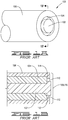
- An end-fired igniter has a geometry such that the igniter tip is located on an axial facing surface.
- a side-fired igniter has a geometry such that the igniter tip is located on a radial facing surface.
- the center electrode and/or the inner ceramic insulator can be applied so as to also create an electrode profile (again relative to a plane perpendicular to the radial direction) that contains nearly-sharp edges.
- a non-uniform electrode perimeter This effectively creates an electrode profile (relative to a plane perpendicular to the axial direction) that contains nearly sharp edges.
- spark igniter of the type used in a furnace having a main burner that supplies a fuel and air mixture. While the present disclosure is described in the context of a spark igniter for a furnace, it will be appreciated that the presently disclosed spark igniter is more broadly applicable as an ignition system for fuels and can be applied to other systems.
- Spark igniter 100 has a center electrode 102 surrounded by an insulator 104 and an outer conducting shell or shell electrode 106 over the insulator such that, at the igniter tip 108, a spark gap 110 is formed between the center electrode 102 and the shell electrode 106, i.e., a gap between the center electrode and the outer electrode shell. Often a semiconductor material is applied to the insulating material at this gap to facilitate sparking. At this spark gap 110, a high-energy spark can pass between a first edge 112 of the center electrode 102 and a second edge 114 of the shell electrode 106.
- spark gap 110 is located on the end surface or axial-facing surface 116 of the igniter tip 108. Accordingly, spark igniter 100 produces an axially-directed spark, i.e., a spark directed along the longitudinal axis of the spark igniter at and away from the axial-facing surface 116. The spark ignites fuel.
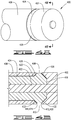
- FIGS. 2A-B depict an axially-directed spark igniter 200.
- Spark igniter 200 allows an HEI system to minimize its output energy while keeping its output voltage unchanged and continuing to maintain its performance in adverse conditions.
- Spark igniter 200 has a plurality of electrodes and an insulator 204 that forms a body.
- the plurality of electrodes comprises a center electrode 202 and a shell electrode 206.
- the center electrode 202 has an inner surface 218, an end 220 and at least a portion of the center electrode forms at least part of the body's outer surface.
- the shell electrode 206 also has an inner surface 222, an end 224 and at least a portion of the shell electrode forms at least part of the body's outer surface.
- the insulator 204 is between the center electrode 202 and the shell electrode 206 and at least a portion of the insulator is uncovered 226 by the center electrode and the shell electrode such that the center electrode and the shell electrode are positioned and electrically insulated from each other such that a spark gap 210 is formed at the igniter tip 208 from a first edge of the center electrode 212 and a second edge of the shell electrode 214.
- the depth of the spark gap 210 is measured from the uncovered portion 226 of the insulator to the outer surface of the body adjacent to the spark gap 210.
- the outer surface of the body adjacent to the spark gap 210 on an axially-directed igniter is the outermost of either the end of the center electrode 220 or the end of the shell electrode 224.
- FIGS. 2A-B depict a structure that will increase the electric field concentration between the two electrodes by applying internal chamfers to the shell electrode, the center electrode and/or the insulator.
- a portion of the insulator 204 adjacent to the uncovered portion 226 of the insulator extends to a chamfered portion 228.
- This chamfered portion 228 mates with a chamfered portion 230 of the inner surface 218 of the center electrode 202 and with a chamfered portion 232 of the inner surface 222 of the shell electrode 206.
- a spark gap 210 is formed from first edge 212 of the center electrode 202 and second edge 214 of the shell electrode 206.
- Center electrode 202 and shell electrode 206 are electrically insulated from each other at spark gap 210. Additionally, the outer surface of shell electrode 206 and the outer surface of center electrode 202 can be chamfered at the spark gap 210. This outer surface chamfering is illustrated by chamfer 234 on the outer surface of shell electrode 206.
- the chamfers create an electrode profile that contain angled edges that can be nearly-sharp, thereby increasing the electric field concentration between the shell electrode and center electrode.
- these chamfers allow for better contact between mating parts and, thus, decrease the chance of a liquid penetrating between mating surfaces.
- FIGS. 2A-B illustrate a decreased well depth over prior art igniter tips.
- the shallower well depth increases the electric field concentration between the two electrodes to produce a flush or "nearly flush" air gap between the shell electrode, the center electrode and the insulator.
- the depth can be less than or equal to 5% of the perimeter of the inner surface of the shell electrode measured at the second edge.
- the depth can also be less than or equal to 5% of the perimeter of the inner surface of the center electrode measured at the first edge.
- FIGS. 3A-B illustrate a radially-directed spark igniter 300 having a design in accordance with more traditional gap designs.
- Spark igniter 300 has a center electrode 302 surrounded by an insulator 304 and an outer conducting shell or shell electrode 306 over the insulator such that, at the igniter tip 308, spark gap 310 is formed between the center electrode 302 and the shell electrode 306, i.e., a gap between the center electrode and the outer electrode shell.
- the igniter tip 308 is configured so that a spark gap 310 is on a radially-facing surface 316 of spark igniter 300.
- a semiconductor material is applied to the insulating material at this gap to facilitate sparking.
- spark igniter 300 produces a radially-directed spark, i.e., a spark directed radially outward and away from the radial-facing surface 316.
- FIGS. 4A-B depict a radially-directed spark igniter 400 in accordance with certain embodiments of the current invention.
- Spark igniter 400 allows an HEI system to minimize its output energy while keeping its output voltage unchanged and continuing to maintain its performance in adverse conditions.
- Spark igniter 400 has a plurality of electrodes and an insulator 404 that forms a body.
- the plurality of electrodes comprises a center electrode 402 and a shell electrode 406.
- the center electrode 402 has an inner surface 418, an end 420 and at least a portion of the center electrode forms at least part of the body's outer surface.
- the shell electrode 406 also has an inner surface 422, an end 424 and at least a portion of the shell electrode forms at least part of the outer surface of the body.
- the insulator 404 is between the center electrode 402 and the shell electrode 406 and at least a portion of the insulator is uncovered 426 by the center electrode and the shell electrode such that the center electrode and the shell electrode are positioned and electrically insulated from each other such that a spark gap 410 is formed at the igniter tip 408 from a first edge 412 of the center electrode 402 and a second edge 414 of the shell electrode 406.
- the depth of the spark gap 410 is measured from the uncovered portion 426 of the insulator to the outer surface of the body.
- the outer surface of the body on a radially-directed igniter is portion of the shell electrode 406 that forms at least part of the outer surface of the body.
- FIGS. 4A-B depict an embodiment of the present disclosure that will increase the electric field concentration between the two electrodes by applying internal chamfers to the shell electrode, the center electrode and/or the insulator. As shown in FIG. 4B , a portion of the insulator 404 adjacent to the uncovered portion 426 of the insulator extends to a chamfered portion 428.
- This chamfered portion 428 mates with a chamfered potion 430 of the inner surface 418 of the center electrode 402 and with a chamfered portion 432 of the inner surface 422 of the shell electrode 406 such that the center electrode 402 and the shell electrode 406 are positioned and electrically insulated from each other such that the spark gap 410 is formed from the first edge 412 of the center electrode 402 and a second edge 414 of the shell electrode 406.
- the chamfers shown in FIGS. 4A-B create an electrode profile that contains nearly-sharp edges thereby increasing the electric field concentration between the shell electrode and center electrode.
- these chamfers allow for better contact between mating parts and, thus, decrease the chance of a liquid penetrating between mating surfaces.
- FIGS. 4A-B increases the electric field concentration between the two electrodes by decreasing the well depth of the igniter tip to produce a flush or "nearly flush" surface gap between the shell electrode, the center electrode and the insulator.
- the depth must be less than or equal to 8% of the perimeter of the outer surface of the body.
- the outer surface of the body on a radially-directed igniter is portion of the shell electrode 406 that forms at least part of the outer surface of the body.
- FIG. 5A depicts the radially-directed spark igniter 300.
- the spark igniter 300 is depicted having exaggerated air gaps 336 between the insulator 304, an inner surface 318 of the center electrode 302 and an inner surface 322 of the shell electrode 306.
- An air gap is the space between the center electrode and shell electrode.
- the air gaps 336 are shown exaggerated to demonstrate that contaminates such as water 338 or other debris may pool or rest upon the air gap of an igniter. Ionized water pooling in the igniter well acts as a conductive path through which current can flow. The addition of the water effectively increases the conductive area and therefore decreases the current density. Current density is the electric current per unit area. A higher density increases an igniter's ability to achieve an arc.
- FIG. 5B discloses an embodiment of a radially-dircctcd igniter 500 having internal chamfers to a center clcctrodc 502, an insulator 504 and the shell electrode 506.
- the internal chamfers aid in reducing the area where water 538 or other debris can accumulate.
- a portion of the insulator 504 adjacent to an uncovered portion 526 of the insulator extends to chamfered portion 528, which mates with chamfered portion 530 of an inner surface 518 of the center electrode 502 and with chamfered portion 532 of an inner surface 522 of the shell electrode 506 such that center electrode 502 and shell electrode 506 are positioned and electrically insulated from each other such that a spark gap 510 is formed from first edge 512 of the center electrode 502 and second edge 514 of the shell electrode 506.
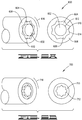
- FIGS. 6A-B depict an axially-directed spark igniter having a non-uniform electrode perimeter that effectively creates an electrode profile (relative to a plane perpendicular to the axial direction) that contains nearly sharp edges.
- the spark igniter 600 comprises a plurality of electrodes and an insulator 604, which are configured to form a body having an outer surface.
- the plurality of electrodes comprises a center electrode 602 and a shell electrode 606.
- the insulator 604 is between the center electrode 602 and the shell electrode 606 and at least a portion of the insulator is uncovered 626 by center electrode 602 and shell electrode 606 such that center electrode 602 and shell electrode 606 are positioned and electrically insulated from each other such that a spark gap 610 is formed from a first edge of the center electrode 612 and a second edge of the shell electrode 614.
- At least one of the first edge and the second edge of the spark gap has a non-uniform geometric shape.
- the non-uniform geometric shape can comprises any one from a group consisting of a star, triangle, quadrilateral, pentagon, hexagon, heptagon, octagon, nonagon, and decagon. Not shown, but included herein is where both the first edge and the second edge of the spark gap have non-uniform geometric shapes.
- FIGS. 6A depicts an illustrative example not part of the invention where the spark gap 610 is located on an axial facing portion 616 of the outer surface of the body and only the second edge 614 of the shell clcctrodc has the non-uniform geometric shape and the shape comprises any one as listed above.
- FIGS. 6B-7 show illustrative examples not part of the invention of an axially-directed spark igniter 700 where the spark gap 710 is located on an axial facing portion 716 of the outer surface of the body and only the first edge 712 of the center electrode has the non-uniform geometric shape and the shape comprises any one as listed above.
- FIGS. 8A-B show another embodiment of a radially-directed spark igniter 800 where the spark gap 810 is located on a radial facing portion 816 of the outer surface of the body and the non-uniform shape is such that a portion of the second edge 814 of the shell electrode does not contact the insulator 804. It should be appreciated, though not shown, that a portion of the first edge 812 of the center electrode can be such that it does not contact the insulator 804. In still another embodiment, both the first edge 812 of the center electrode and the second edge 814 of the shell electrode are non-uniform in such a way that a portion of both do not contact the insulator 804.
- FIG. 9 shows igniters having a striped or partial semiconductor profile.
- FIG. 9A shows a striped or partial semiconductor profile on an axially-directed spark igniter 900 not part of the invention
- a semiconductor 940 is deposited on the insulator 904 at the bottom of the spark gap 910.
- the semiconductor 940 forms a conductive path between the center electrode 902 and the shell electrode 906.
- This semiconductor can be a film applied to the insulator itself. Once the pathway is established, the electrical energy is able to flow unresisted except for circuit impedance, thereby creating a very high current and energy spark at spark gap 910.
- FIG. 9B demonstrates that a striped or partial semiconductor profile can also be applied to a radially-directed spark igniter 1000.
- the current density across the semiconductor increases thereby increasing the spark igniter's ability to achieve an arc. It should be appreciated that having a striped or partial semiconductor profile can be used as a stand alone modification of the present disclosure or in conjunction with any other embodiment disclosed herein.
- a low energy HEI system ( ⁇ 0.33J) was utilized which could be mated with igniters of approximately 1 ⁇ 4 inch diameter.
- the igniter OD defined as the outer diameter (OD) of the shell electrode, is 1 ⁇ 4 inch in diameter.
- Table 1 reflects the results of various experiments carried out with side-fire designs. The results demonstrate that by decreasing the well depth and having chamfered electrodes and insulators, the electric field concentration between the electrodes increases. Increasing the electric field concentration increases the ability to achieve an arc, indicated by a successful spark test.
- Table 1 Development Project #1 Data Test Igniter Geometry Igniter OD (inches) Igniter Gap Width (inches) Well Depth (inches) Exciter Output Energy (Joules) Successful Spark Test? #1 ⁇ Non-flush 0.25 0.04 0.04 0.33 No ⁇ No internal chamfers ⁇ Side-fired ( FIG. 3 ) ⁇ Flush gap 0.25 0.04 0.002 0.33 Yes ⁇ Chamfered ⁇ Side-fired ( FIG. 4 ) ⁇ Flush gap 0.25 0.06-0.08 0.002 0.33 No ⁇ Chamfered ⁇ Side-fired (Similar to FIG. 4 ) ⁇ Flush gap 0.25 0.06-0.08 0.002 0.33 Yes ⁇ Chamfered ⁇ Side-fired -Semiconductor striped (Similar to FIG. 4 )
- a low energy HEI system ( ⁇ 1.5J) was utilized that could be mated with igniters of approximately 1 ⁇ 2 inch diameter.
- the igniter OD defined as the outer diameter (OD) of the shell electrode, is 1 ⁇ 2 inch in diameter.
- end-fired igniter tips or axially-directed spark igniters with a focus on keeping the air gap as flush as possible were designed. (See Table 2 for geometry specifications.) Table 2 reflects the results of various experiments carried out with end-fired designs.
- Table 2 demonstrates that non-uniform electrode profiles, specifically where the center electrode on an axially-directed spark igniter is non-uniform, creates an increase of the electric field concentration between the center and shell electrode thereby increasing the chance of successful spark in adverse conditions.
- Table 2 Development Project #2 Data Test Igniter Geometry Igniter OD (inches) Igniter Gap Width (inches) Well Depth (inches) Exciter Output Energy (Joules) Successful Spark Test, Pouring Water? ⁇ Non-flush 0.50 0.04 0.04 1.5 No ⁇ No internal chamfers ⁇ End-fired ( FIG.
- FIG. 7A ⁇ Non-flush 0.625 0.06 0.125 1.5 No ⁇ No internal chamfers ⁇ End-fired ( FIG. 1 ) ⁇ Non-flush 0.625 0.06 0.125 1.5 Yes ⁇ No internal chamfers ⁇ End-fired -Pointed Electrode ( FIG. 7B )
Landscapes
- Engineering & Computer Science (AREA)
- Chemical & Material Sciences (AREA)
- Combustion & Propulsion (AREA)
- Mechanical Engineering (AREA)
- General Engineering & Computer Science (AREA)
- Spark Plugs (AREA)
Claims (5)
- Radial gerichteter Funkenzünder (400), umfassend:eine Vielzahl von Elektroden und einen Isolator (404), die konfiguriert sind, einen Körper zu bilden, der eine Außenfläche aufweist;wobei die Vielzahl von Elektroden umfasst:eine Mittelelektrode (402), die ein Ende (420) aufweist, wobei mindestens ein Abschnitt der Mittelelektrode (402) mindestens Teil der Außenfläche des Körpers bildet; undeine Hüllenelektrode (406), die eine Innenfläche (422) und ein Ende (424) aufweist, wobei mindestens ein Abschnitt der Hüllenelektrode (406) mindestens Teil der Außenfläche des Körpers bildet;wobei der Isolator (404) zwischen der Mittelelektrode (402) und der Hüllenelektrode (406) positioniert ist, wobei mindestens ein Abschnitt (426) des Isolators (404) von der Mittelelektrode (402) und der Hüllenelektrode (406) unbedeckt ist, sodass ein Funkenspalt (410) von einem ersten Rand (412) der Mittelelektrode (402) und einem zweiten Rand (414) der Hüllenelektrode (406) gebildet ist;wobei der Funkenspalt (410) an einer radial gerichteten Oberfläche des Funkenzünders (400) liegt und mindestens eines der Enden mindestens einen des ersten Rands (412) und des zweiten Rands (414) des Funkenspalts (410) bildet, wobei mindestens ein Abschnitt mindestens eines Endes den Isolator (404) nicht kontaktiert; undeine Tiefe des Funkenspalts (410) von dem unbedeckten Abschnitt (426) des Isolators (404) zu der Außenfläche des Körpers gemessen wird, wobei die Tiefe kleiner als 8% des Außenflächenumfangs des Körpers ist.
- Funkenzünder nach Anspruch 1, wobei die Tiefe kleiner oder gleich 5% des Umfangs der Innenfläche (422) der Hüllenelektrode (406), gemessen am zweiten Rand (414) ist.
- Funkenzünder nach Anspruch 1 oder Anspruch 2, wobei ein Halbleitermaterial (940) auf den unbedeckten Abschnitt (426) des Isolators (404) aufgebracht wird, sodass das Halbleitermaterial (940) eine Teilabdeckung des unbedeckten Abschnitts (426) des Isolators (404) aufweist.
- Funkenzünder nach Anspruch 3, wobei das Halbleitermaterial (940) in Streifen aufgebracht wird, sodass mindestens eine Fläche des unbedeckten Abschnitts (426) des Isolators (404) ohne ein Halbleitermaterial (940) ist.
- Funkenzünder nach einem der vorstehenden Ansprüche, wobei mindestens einer des ersten Rands (412) und des zweiten Rands (414) eine geometrische Form aufweist, die eine beliebige aus einer Gruppe umfasst, bestehend aus einem Stern, Dreieck, Viereck, Fünfeck, Sechseck, Siebeneck, Achteck, Neuneck und Zehneck.
Applications Claiming Priority (2)
| Application Number | Priority Date | Filing Date | Title |
|---|---|---|---|
| US201361920812P | 2013-12-26 | 2013-12-26 | |
| US14/566,551 US9484717B2 (en) | 2013-12-26 | 2014-12-10 | High energy ignition spark igniter |
Publications (3)
| Publication Number | Publication Date |
|---|---|
| EP2889970A2 EP2889970A2 (de) | 2015-07-01 |
| EP2889970A3 EP2889970A3 (de) | 2015-09-30 |
| EP2889970B1 true EP2889970B1 (de) | 2021-01-20 |
Family
ID=52347096
Family Applications (1)
| Application Number | Title | Priority Date | Filing Date |
|---|---|---|---|
| EP14199022.6A Active EP2889970B1 (de) | 2013-12-26 | 2014-12-18 | Verbesserter hochenergetischer Zündfunkenzünder |
Country Status (7)
| Country | Link |
|---|---|
| US (1) | US9484717B2 (de) |
| EP (1) | EP2889970B1 (de) |
| JP (1) | JP6189282B2 (de) |
| KR (1) | KR101755080B1 (de) |
| CN (1) | CN104748150B (de) |
| CA (1) | CA2875267C (de) |
| SG (1) | SG10201408452UA (de) |
Families Citing this family (10)
| Publication number | Priority date | Publication date | Assignee | Title |
|---|---|---|---|---|
| CN105351101B (zh) * | 2015-11-01 | 2017-04-26 | 四川泛华航空仪表电器有限公司 | 振荡自补偿点火功率集成模块 |
| WO2018181654A1 (ja) * | 2017-03-31 | 2018-10-04 | 株式会社デンソー | 内燃機関用のスパークプラグ |
| JP7022628B2 (ja) | 2017-03-31 | 2022-02-18 | 株式会社Soken | 内燃機関用のスパークプラグ |
| CN108613216A (zh) * | 2017-12-22 | 2018-10-02 | 上海富良环保科技有限公司 | 一种电弧式点烟器及方法 |
| JP7058193B2 (ja) * | 2018-07-25 | 2022-04-21 | 株式会社Soken | 内燃機関用のスパークプラグ |
| CN109630279A (zh) * | 2019-01-17 | 2019-04-16 | 中国人民解放军空军工程大学 | 多孔雾化等离子体燃油喷嘴 |
| WO2021072458A1 (en) | 2019-10-15 | 2021-04-22 | Innio Jenbacher Gmbh & Co Og | Spark plug and method for producing a spark plug |
| DE102020206863A1 (de) | 2020-06-02 | 2021-12-02 | Dieter Kutzner | Hochspannungszünder |
| US11769991B2 (en) | 2021-10-05 | 2023-09-26 | Unison Industries, Llc | Glow discharge tube with a set of electrodes within a gas-sealed envelope |
| DE102022117210A1 (de) | 2022-07-11 | 2024-01-11 | Dürr Systems Ag | Vorrichtung zur Bereitstellung einer elektrischen Gas- oder Funkenentladung und Verfahren zur Zündung eines Brenners |
Citations (2)
| Publication number | Priority date | Publication date | Assignee | Title |
|---|---|---|---|---|
| JPS5772287A (en) * | 1980-10-24 | 1982-05-06 | Nissan Motor | Ignition plug |
| US5187404A (en) * | 1991-08-05 | 1993-02-16 | Cooper Industries, Inc. | Surface gap igniter |
Family Cites Families (56)
| Publication number | Priority date | Publication date | Assignee | Title |
|---|---|---|---|---|
| US2332210A (en) | 1943-10-19 | Ignition apparatus | ||
| US2640473A (en) * | 1953-06-02 | Surface discharge spark plug fob | ||
| US2859370A (en) * | 1958-11-04 | Low-tension sparking plug for | ||
| US2064089A (en) | 1936-01-25 | 1936-12-15 | Stemmeler Fred | Spark plug |
| US2129576A (en) | 1936-09-16 | 1938-09-06 | Frank A Gorny | Spark plug |
| US2214958A (en) | 1939-04-24 | 1940-09-17 | August R Layer | Spark plug |
| GB536460A (en) * | 1939-12-09 | 1941-05-15 | Plessey Co Ltd | Improvements in sparking plugs for internal combustion engines |
| GB545351A (en) | 1940-03-13 | 1942-05-21 | H B Motor Corp | Improvements in or relating to spark plugs |
| US2501826A (en) | 1945-04-06 | 1950-03-28 | Frederick I Mccarthy | Spark plug |
| US2689556A (en) * | 1951-07-31 | 1954-09-21 | Smitsvonk Nv | Surface discharge spark plug for low voltages and condenser discharge |
| GB745016A (en) | 1952-10-31 | 1956-02-15 | Lodge Plugs Ltd | Improvements in or relating to surface discharge sparking plugs or other igniters |
| GB819256A (en) | 1955-11-09 | 1959-09-02 | Orr & Sembower Inc | Pilot ignition unit for fuel burners |
| US2953704A (en) * | 1956-07-26 | 1960-09-20 | Bendix Corp | Electrical discharge device |
| GB848070A (en) | 1956-12-20 | 1960-09-14 | Babcock & Wilcox Ltd | Improvements in igniting means for fluent fuel fired furnaces and to surface discharge sparking plugs and methods of manufacture thereof |
| GB855440A (en) | 1956-12-29 | 1960-11-30 | Lodge Plugs Ltd | Improvements in or relating to surface discharge sparking plugs or other ignition devices |
| US3073121A (en) | 1958-02-06 | 1963-01-15 | Bendix Corp | Igniter |
| US3046434A (en) * | 1958-04-21 | 1962-07-24 | Champion Spark Plug Co | Electrically semi-conducting engobe coating |
| US2906922A (en) | 1958-05-28 | 1959-09-29 | Joslyn Mfg & Supply Co | Spark gap unit |
| US3312848A (en) | 1964-05-13 | 1967-04-04 | Baum Herman | Spark plug having concentric radially spaced electrodes |
| GB1146244A (en) * | 1967-01-25 | 1969-03-19 | Rolls Royce | Spark igniter |
| US3558959A (en) * | 1968-04-24 | 1971-01-26 | Carborundum Co | Silicon carbide semi-conductor igniter structure |
| US3883762A (en) * | 1974-06-17 | 1975-05-13 | Bendix Corp | Electrical discharge device comprising an insulator body having an electrically semi-conducting coating formed thereon |
| US4142121A (en) * | 1975-09-08 | 1979-02-27 | Smiths Industries Limited | Electrical igniters |
| FR2329088A1 (fr) | 1975-10-21 | 1977-05-20 | Djeddah Jacques | Bougie ou electrode d'allumage pour bruleur |
| GB1570125A (en) * | 1977-03-11 | 1980-06-25 | Smiths Industries Ltd | Electrical igniters and to methods applicable to the manufacture thereof |
| US4187825A (en) | 1977-10-17 | 1980-02-12 | Curtiss-Wright Corporation | Pilot fuel ignited stratified charge rotary combustion engine and fuel injector therefor |
| US4315298A (en) | 1980-04-28 | 1982-02-09 | The Bendix Corporation | Igniter plug |
| GB2157816B (en) | 1984-04-18 | 1988-03-16 | Gas Ignition Company Limited | Electrode asembly for gas ignition |
| JPS6132979A (ja) | 1984-07-25 | 1986-02-15 | 株式会社デンソー | 小型点火プラグ |
| US4695758A (en) | 1984-07-25 | 1987-09-22 | Nippondenso Co., Ltd. | Small-sized spark plug having a spark gap parallel to an axis running through the center electrode |
| JPS6132978A (ja) * | 1984-07-25 | 1986-02-15 | 株式会社デンソー | 小型点火プラグ |
| CA1265431A (en) | 1985-01-08 | 1990-02-06 | Roderick John Macdonald | Electrode device for flare stack ignitor |
| JPH01161691A (ja) * | 1988-09-30 | 1989-06-26 | Ryohei Kashiwabara | 点火栓による燃焼法 |
| US5007389A (en) * | 1987-12-17 | 1991-04-16 | Ryohei Kashiwara | Ignition plug for internal combustion engines and a process for igniting gas mixture by the use thereof |
| JPH01163986A (ja) | 1987-12-18 | 1989-06-28 | Ngk Spark Plug Co Ltd | 低電圧沿面放電型イグナイタプラグ |
| JPH077694B2 (ja) | 1988-05-09 | 1995-01-30 | 日本特殊陶業株式会社 | 沿面ギャップ型イグナイタプラグの製造方法 |
| CN2033948U (zh) * | 1988-05-19 | 1989-03-08 | 南京火花塞研究所 | 多极半导体火花塞 |
| IT8867555A0 (it) * | 1988-06-10 | 1988-06-10 | Magneti Marelli Spa | Candela di accensione a scarica se misuperficiale per motore a combustione interna e procedimento per la realizzazione degli elettrodi di massa di tale candela |
| US5074262A (en) | 1990-10-15 | 1991-12-24 | Mcabee Mac | Spark device for internal combustion engines |
| GB2255590B (en) * | 1991-05-14 | 1994-08-03 | Ngk Spark Plug Co | An igniter plug |
| JP2001524656A (ja) | 1997-11-25 | 2001-12-04 | マクソン コーポレイション | 一体型イグニッション付き酸素−燃料パイロット |
| ATE282253T1 (de) | 1998-03-02 | 2004-11-15 | Pyrotek Entpr Inc | Zündkerze mit verbesserten wirkungsmerkmalen |
| US6495948B1 (en) | 1998-03-02 | 2002-12-17 | Pyrotek Enterprises, Inc. | Spark plug |
| CN2371465Y (zh) * | 1999-02-24 | 2000-03-29 | 张燕江 | 圆台诱导电体高能燃油点火电极 |
| US6048196A (en) | 1999-09-13 | 2000-04-11 | Eclipse Combustion, Inc. | Durable self-grounding igniter for industrial burners |
| US6414419B1 (en) * | 1999-12-29 | 2002-07-02 | Sei Y. Kim | Ignition spark plug |
| GB2361264A (en) | 2000-04-10 | 2001-10-17 | Fed Mogul Ignition | Surface discharge spark plug for i.c. engines |
| AU2001248945A1 (en) | 2000-08-11 | 2002-02-25 | Vladimir Nikolaevich Alexandrov | Spark plug |
| FR2816119B1 (fr) | 2000-10-27 | 2003-02-21 | Renault | Bougie a effet de surface a etincelle radiale |
| US20050189858A1 (en) * | 2004-03-01 | 2005-09-01 | Chin-Fa Chang | Spark plug |
| JP4696981B2 (ja) * | 2006-03-14 | 2011-06-08 | 株式会社デンソー | 内燃機関用のスパークプラグ |
| US7699602B2 (en) * | 2006-05-10 | 2010-04-20 | Owens-Brockway Glass Container Inc. | Glassware mold lubrication burner |
| US8534041B2 (en) * | 2009-12-23 | 2013-09-17 | Unison Industries, Llc | Apparatus and assembly for a spark igniter having tangential embedded pins |
| DE102010010109B4 (de) | 2010-03-04 | 2012-03-15 | Multitorch Gmbh | Vorkammerzündkerze |
| JP5406249B2 (ja) * | 2011-07-06 | 2014-02-05 | 日本特殊陶業株式会社 | イグナイタプラグおよびイグナイタプラグの製造方法 |
| US20140292177A1 (en) * | 2013-04-02 | 2014-10-02 | Mark Nagy | Lateral Traverse Discharge Spark Plug |
-
2014
- 2014-12-10 US US14/566,551 patent/US9484717B2/en active Active
- 2014-12-17 CA CA2875267A patent/CA2875267C/en active Active
- 2014-12-17 SG SG10201408452UA patent/SG10201408452UA/en unknown
- 2014-12-18 EP EP14199022.6A patent/EP2889970B1/de active Active
- 2014-12-25 JP JP2014262128A patent/JP6189282B2/ja active Active
- 2014-12-26 KR KR1020140190379A patent/KR101755080B1/ko active Active
- 2014-12-26 CN CN201410834555.6A patent/CN104748150B/zh active Active
Patent Citations (2)
| Publication number | Priority date | Publication date | Assignee | Title |
|---|---|---|---|---|
| JPS5772287A (en) * | 1980-10-24 | 1982-05-06 | Nissan Motor | Ignition plug |
| US5187404A (en) * | 1991-08-05 | 1993-02-16 | Cooper Industries, Inc. | Surface gap igniter |
Also Published As
| Publication number | Publication date |
|---|---|
| CN104748150B (zh) | 2017-06-23 |
| EP2889970A2 (de) | 2015-07-01 |
| KR20150076130A (ko) | 2015-07-06 |
| SG10201408452UA (en) | 2015-07-30 |
| CA2875267C (en) | 2017-09-19 |
| CN104748150A (zh) | 2015-07-01 |
| KR101755080B1 (ko) | 2017-07-19 |
| US9484717B2 (en) | 2016-11-01 |
| US20150188292A1 (en) | 2015-07-02 |
| JP2015129628A (ja) | 2015-07-16 |
| JP6189282B2 (ja) | 2017-08-30 |
| EP2889970A3 (de) | 2015-09-30 |
| CA2875267A1 (en) | 2015-06-26 |
Similar Documents
| Publication | Publication Date | Title |
|---|---|---|
| CA2875267C (en) | Improved high energy ignition spark igniter | |
| US9843166B2 (en) | Spark plug and method for manufacturing spark plug | |
| US20110133625A1 (en) | Spark plug and method of manufacturing the same | |
| KR101738798B1 (ko) | 스파크 플러그 | |
| JP2011175980A5 (de) | ||
| WO2022030072A1 (ja) | スパークプラグ | |
| KR101822723B1 (ko) | 점화 플러그 | |
| CN102714398B (zh) | 火花塞 | |
| EP2696453B1 (de) | Zündkerze | |
| EP2202854B1 (de) | Zündkerze und Zündungssystem | |
| KR101348019B1 (ko) | 플라즈마 젯 점화 플러그 | |
| JP6034199B2 (ja) | プラズマジェット点火プラグ | |
| CN103959581B (zh) | 火花塞 | |
| JP5140718B2 (ja) | プラズマジェット点火プラグ | |
| JP2016004730A (ja) | スパークプラグ | |
| US9112335B2 (en) | Spark plug and spark plug electrode | |
| US9660424B2 (en) | Spark plug | |
| JP2020004679A (ja) | 点火プラグ | |
| JP6214473B2 (ja) | プラズマジェットプラグ | |
| JP5671446B2 (ja) | プラズマジェット点火プラグ | |
| JP3265211B2 (ja) | スパークプラグ | |
| JP2021086819A (ja) | スパークプラグ | |
| JP2005203349A (ja) | スパークプラグ |
Legal Events
| Date | Code | Title | Description |
|---|---|---|---|
| PUAI | Public reference made under article 153(3) epc to a published international application that has entered the european phase |
Free format text: ORIGINAL CODE: 0009012 |
|
| 17P | Request for examination filed |
Effective date: 20141218 |
|
| AK | Designated contracting states |
Kind code of ref document: A2 Designated state(s): AL AT BE BG CH CY CZ DE DK EE ES FI FR GB GR HR HU IE IS IT LI LT LU LV MC MK MT NL NO PL PT RO RS SE SI SK SM TR |
|
| AX | Request for extension of the european patent |
Extension state: BA ME |
|
| PUAL | Search report despatched |
Free format text: ORIGINAL CODE: 0009013 |
|
| AK | Designated contracting states |
Kind code of ref document: A3 Designated state(s): AL AT BE BG CH CY CZ DE DK EE ES FI FR GB GR HR HU IE IS IT LI LT LU LV MC MK MT NL NO PL PT RO RS SE SI SK SM TR |
|
| AX | Request for extension of the european patent |
Extension state: BA ME |
|
| RIC1 | Information provided on ipc code assigned before grant |
Ipc: H01T 13/20 20060101ALI20150821BHEP Ipc: H01T 13/52 20060101ALI20150821BHEP Ipc: H01T 13/00 20060101AFI20150821BHEP Ipc: H01T 1/22 20060101ALI20150821BHEP Ipc: F02C 7/266 20060101ALI20150821BHEP Ipc: F23Q 3/00 20060101ALI20150821BHEP |
|
| R17P | Request for examination filed (corrected) |
Effective date: 20160330 |
|
| RBV | Designated contracting states (corrected) |
Designated state(s): AL AT BE BG CH CY CZ DE DK EE ES FI FR GB GR HR HU IE IS IT LI LT LU LV MC MK MT NL NO PL PT RO RS SE SI SK SM TR |
|
| STAA | Information on the status of an ep patent application or granted ep patent |
Free format text: STATUS: EXAMINATION IS IN PROGRESS |
|
| 17Q | First examination report despatched |
Effective date: 20181005 |
|
| GRAP | Despatch of communication of intention to grant a patent |
Free format text: ORIGINAL CODE: EPIDOSNIGR1 |
|
| STAA | Information on the status of an ep patent application or granted ep patent |
Free format text: STATUS: GRANT OF PATENT IS INTENDED |
|
| INTG | Intention to grant announced |
Effective date: 20200922 |
|
| GRAS | Grant fee paid |
Free format text: ORIGINAL CODE: EPIDOSNIGR3 |
|
| GRAA | (expected) grant |
Free format text: ORIGINAL CODE: 0009210 |
|
| STAA | Information on the status of an ep patent application or granted ep patent |
Free format text: STATUS: THE PATENT HAS BEEN GRANTED |
|
| AK | Designated contracting states |
Kind code of ref document: B1 Designated state(s): AL AT BE BG CH CY CZ DE DK EE ES FI FR GB GR HR HU IE IS IT LI LT LU LV MC MK MT NL NO PL PT RO RS SE SI SK SM TR |
|
| REG | Reference to a national code |
Ref country code: GB Ref legal event code: FG4D |
|
| REG | Reference to a national code |
Ref country code: CH Ref legal event code: EP |
|
| REG | Reference to a national code |
Ref country code: DE Ref legal event code: R096 Ref document number: 602014074354 Country of ref document: DE |
|
| REG | Reference to a national code |
Ref country code: AT Ref legal event code: REF Ref document number: 1357177 Country of ref document: AT Kind code of ref document: T Effective date: 20210215 |
|
| REG | Reference to a national code |
Ref country code: IE Ref legal event code: FG4D |
|
| REG | Reference to a national code |
Ref country code: NL Ref legal event code: FP |
|
| REG | Reference to a national code |
Ref country code: LT Ref legal event code: MG9D |
|
| REG | Reference to a national code |
Ref country code: AT Ref legal event code: MK05 Ref document number: 1357177 Country of ref document: AT Kind code of ref document: T Effective date: 20210120 |
|
| PG25 | Lapsed in a contracting state [announced via postgrant information from national office to epo] |
Ref country code: GR Free format text: LAPSE BECAUSE OF FAILURE TO SUBMIT A TRANSLATION OF THE DESCRIPTION OR TO PAY THE FEE WITHIN THE PRESCRIBED TIME-LIMIT Effective date: 20210421 Ref country code: HR Free format text: LAPSE BECAUSE OF FAILURE TO SUBMIT A TRANSLATION OF THE DESCRIPTION OR TO PAY THE FEE WITHIN THE PRESCRIBED TIME-LIMIT Effective date: 20210120 Ref country code: FI Free format text: LAPSE BECAUSE OF FAILURE TO SUBMIT A TRANSLATION OF THE DESCRIPTION OR TO PAY THE FEE WITHIN THE PRESCRIBED TIME-LIMIT Effective date: 20210120 Ref country code: PT Free format text: LAPSE BECAUSE OF FAILURE TO SUBMIT A TRANSLATION OF THE DESCRIPTION OR TO PAY THE FEE WITHIN THE PRESCRIBED TIME-LIMIT Effective date: 20210520 Ref country code: LT Free format text: LAPSE BECAUSE OF FAILURE TO SUBMIT A TRANSLATION OF THE DESCRIPTION OR TO PAY THE FEE WITHIN THE PRESCRIBED TIME-LIMIT Effective date: 20210120 Ref country code: BG Free format text: LAPSE BECAUSE OF FAILURE TO SUBMIT A TRANSLATION OF THE DESCRIPTION OR TO PAY THE FEE WITHIN THE PRESCRIBED TIME-LIMIT Effective date: 20210420 Ref country code: NO Free format text: LAPSE BECAUSE OF FAILURE TO SUBMIT A TRANSLATION OF THE DESCRIPTION OR TO PAY THE FEE WITHIN THE PRESCRIBED TIME-LIMIT Effective date: 20210420 |
|
| PG25 | Lapsed in a contracting state [announced via postgrant information from national office to epo] |
Ref country code: PL Free format text: LAPSE BECAUSE OF FAILURE TO SUBMIT A TRANSLATION OF THE DESCRIPTION OR TO PAY THE FEE WITHIN THE PRESCRIBED TIME-LIMIT Effective date: 20210120 Ref country code: LV Free format text: LAPSE BECAUSE OF FAILURE TO SUBMIT A TRANSLATION OF THE DESCRIPTION OR TO PAY THE FEE WITHIN THE PRESCRIBED TIME-LIMIT Effective date: 20210120 Ref country code: RS Free format text: LAPSE BECAUSE OF FAILURE TO SUBMIT A TRANSLATION OF THE DESCRIPTION OR TO PAY THE FEE WITHIN THE PRESCRIBED TIME-LIMIT Effective date: 20210120 Ref country code: AT Free format text: LAPSE BECAUSE OF FAILURE TO SUBMIT A TRANSLATION OF THE DESCRIPTION OR TO PAY THE FEE WITHIN THE PRESCRIBED TIME-LIMIT Effective date: 20210120 Ref country code: SE Free format text: LAPSE BECAUSE OF FAILURE TO SUBMIT A TRANSLATION OF THE DESCRIPTION OR TO PAY THE FEE WITHIN THE PRESCRIBED TIME-LIMIT Effective date: 20210120 |
|
| PG25 | Lapsed in a contracting state [announced via postgrant information from national office to epo] |
Ref country code: IS Free format text: LAPSE BECAUSE OF FAILURE TO SUBMIT A TRANSLATION OF THE DESCRIPTION OR TO PAY THE FEE WITHIN THE PRESCRIBED TIME-LIMIT Effective date: 20210520 |
|
| REG | Reference to a national code |
Ref country code: DE Ref legal event code: R097 Ref document number: 602014074354 Country of ref document: DE |
|
| PG25 | Lapsed in a contracting state [announced via postgrant information from national office to epo] |
Ref country code: CZ Free format text: LAPSE BECAUSE OF FAILURE TO SUBMIT A TRANSLATION OF THE DESCRIPTION OR TO PAY THE FEE WITHIN THE PRESCRIBED TIME-LIMIT Effective date: 20210120 Ref country code: EE Free format text: LAPSE BECAUSE OF FAILURE TO SUBMIT A TRANSLATION OF THE DESCRIPTION OR TO PAY THE FEE WITHIN THE PRESCRIBED TIME-LIMIT Effective date: 20210120 Ref country code: SM Free format text: LAPSE BECAUSE OF FAILURE TO SUBMIT A TRANSLATION OF THE DESCRIPTION OR TO PAY THE FEE WITHIN THE PRESCRIBED TIME-LIMIT Effective date: 20210120 |
|
| PLBE | No opposition filed within time limit |
Free format text: ORIGINAL CODE: 0009261 |
|
| STAA | Information on the status of an ep patent application or granted ep patent |
Free format text: STATUS: NO OPPOSITION FILED WITHIN TIME LIMIT |
|
| PG25 | Lapsed in a contracting state [announced via postgrant information from national office to epo] |
Ref country code: ES Free format text: LAPSE BECAUSE OF FAILURE TO SUBMIT A TRANSLATION OF THE DESCRIPTION OR TO PAY THE FEE WITHIN THE PRESCRIBED TIME-LIMIT Effective date: 20210120 Ref country code: DK Free format text: LAPSE BECAUSE OF FAILURE TO SUBMIT A TRANSLATION OF THE DESCRIPTION OR TO PAY THE FEE WITHIN THE PRESCRIBED TIME-LIMIT Effective date: 20210120 Ref country code: RO Free format text: LAPSE BECAUSE OF FAILURE TO SUBMIT A TRANSLATION OF THE DESCRIPTION OR TO PAY THE FEE WITHIN THE PRESCRIBED TIME-LIMIT Effective date: 20210120 Ref country code: SK Free format text: LAPSE BECAUSE OF FAILURE TO SUBMIT A TRANSLATION OF THE DESCRIPTION OR TO PAY THE FEE WITHIN THE PRESCRIBED TIME-LIMIT Effective date: 20210120 |
|
| 26N | No opposition filed |
Effective date: 20211021 |
|
| PG25 | Lapsed in a contracting state [announced via postgrant information from national office to epo] |
Ref country code: AL Free format text: LAPSE BECAUSE OF FAILURE TO SUBMIT A TRANSLATION OF THE DESCRIPTION OR TO PAY THE FEE WITHIN THE PRESCRIBED TIME-LIMIT Effective date: 20210120 |
|
| PG25 | Lapsed in a contracting state [announced via postgrant information from national office to epo] |
Ref country code: SI Free format text: LAPSE BECAUSE OF FAILURE TO SUBMIT A TRANSLATION OF THE DESCRIPTION OR TO PAY THE FEE WITHIN THE PRESCRIBED TIME-LIMIT Effective date: 20210120 |
|
| PG25 | Lapsed in a contracting state [announced via postgrant information from national office to epo] |
Ref country code: IS Free format text: LAPSE BECAUSE OF FAILURE TO SUBMIT A TRANSLATION OF THE DESCRIPTION OR TO PAY THE FEE WITHIN THE PRESCRIBED TIME-LIMIT Effective date: 20210520 |
|
| PG25 | Lapsed in a contracting state [announced via postgrant information from national office to epo] |
Ref country code: MC Free format text: LAPSE BECAUSE OF FAILURE TO SUBMIT A TRANSLATION OF THE DESCRIPTION OR TO PAY THE FEE WITHIN THE PRESCRIBED TIME-LIMIT Effective date: 20210120 |
|
| REG | Reference to a national code |
Ref country code: CH Ref legal event code: PL |
|
| REG | Reference to a national code |
Ref country code: BE Ref legal event code: MM Effective date: 20211231 |
|
| PG25 | Lapsed in a contracting state [announced via postgrant information from national office to epo] |
Ref country code: LU Free format text: LAPSE BECAUSE OF NON-PAYMENT OF DUE FEES Effective date: 20211218 Ref country code: IE Free format text: LAPSE BECAUSE OF NON-PAYMENT OF DUE FEES Effective date: 20211218 |
|
| PG25 | Lapsed in a contracting state [announced via postgrant information from national office to epo] |
Ref country code: BE Free format text: LAPSE BECAUSE OF NON-PAYMENT OF DUE FEES Effective date: 20211231 |
|
| PG25 | Lapsed in a contracting state [announced via postgrant information from national office to epo] |
Ref country code: LI Free format text: LAPSE BECAUSE OF NON-PAYMENT OF DUE FEES Effective date: 20211231 Ref country code: CH Free format text: LAPSE BECAUSE OF NON-PAYMENT OF DUE FEES Effective date: 20211231 |
|
| PG25 | Lapsed in a contracting state [announced via postgrant information from national office to epo] |
Ref country code: HU Free format text: LAPSE BECAUSE OF FAILURE TO SUBMIT A TRANSLATION OF THE DESCRIPTION OR TO PAY THE FEE WITHIN THE PRESCRIBED TIME-LIMIT; INVALID AB INITIO Effective date: 20141218 |
|
| PG25 | Lapsed in a contracting state [announced via postgrant information from national office to epo] |
Ref country code: CY Free format text: LAPSE BECAUSE OF FAILURE TO SUBMIT A TRANSLATION OF THE DESCRIPTION OR TO PAY THE FEE WITHIN THE PRESCRIBED TIME-LIMIT Effective date: 20210120 |
|
| P01 | Opt-out of the competence of the unified patent court (upc) registered |
Effective date: 20230528 |
|
| PG25 | Lapsed in a contracting state [announced via postgrant information from national office to epo] |
Ref country code: MK Free format text: LAPSE BECAUSE OF FAILURE TO SUBMIT A TRANSLATION OF THE DESCRIPTION OR TO PAY THE FEE WITHIN THE PRESCRIBED TIME-LIMIT Effective date: 20210120 |
|
| PG25 | Lapsed in a contracting state [announced via postgrant information from national office to epo] |
Ref country code: MT Free format text: LAPSE BECAUSE OF FAILURE TO SUBMIT A TRANSLATION OF THE DESCRIPTION OR TO PAY THE FEE WITHIN THE PRESCRIBED TIME-LIMIT Effective date: 20210120 |
|
| PGFP | Annual fee paid to national office [announced via postgrant information from national office to epo] |
Ref country code: NL Payment date: 20251003 Year of fee payment: 12 |
|
| PG25 | Lapsed in a contracting state [announced via postgrant information from national office to epo] |
Ref country code: TR Free format text: LAPSE BECAUSE OF FAILURE TO SUBMIT A TRANSLATION OF THE DESCRIPTION OR TO PAY THE FEE WITHIN THE PRESCRIBED TIME-LIMIT Effective date: 20210120 |
|
| PGFP | Annual fee paid to national office [announced via postgrant information from national office to epo] |
Ref country code: DE Payment date: 20250930 Year of fee payment: 12 |
|
| PGFP | Annual fee paid to national office [announced via postgrant information from national office to epo] |
Ref country code: GB Payment date: 20251001 Year of fee payment: 12 |
|
| PGFP | Annual fee paid to national office [announced via postgrant information from national office to epo] |
Ref country code: IT Payment date: 20251121 Year of fee payment: 12 |
|
| PGFP | Annual fee paid to national office [announced via postgrant information from national office to epo] |
Ref country code: FR Payment date: 20251008 Year of fee payment: 12 |