EP2889188B1 - Nicht synchronisiertes getriebe und automobilkarosserie - Google Patents
Nicht synchronisiertes getriebe und automobilkarosserie Download PDFInfo
- Publication number
- EP2889188B1 EP2889188B1 EP13830445.6A EP13830445A EP2889188B1 EP 2889188 B1 EP2889188 B1 EP 2889188B1 EP 13830445 A EP13830445 A EP 13830445A EP 2889188 B1 EP2889188 B1 EP 2889188B1
- Authority
- EP
- European Patent Office
- Prior art keywords
- crash box
- cross
- corner portions
- pair
- tubular body
- Prior art date
- Legal status (The legal status is an assumption and is not a legal conclusion. Google has not performed a legal analysis and makes no representation as to the accuracy of the status listed.)
- Active
Links
- 230000002093 peripheral effect Effects 0.000 claims description 38
- 230000007423 decrease Effects 0.000 claims description 11
- 229910052751 metal Inorganic materials 0.000 claims description 5
- 239000002184 metal Substances 0.000 claims description 5
- 238000005452 bending Methods 0.000 description 29
- 238000010586 diagram Methods 0.000 description 23
- 230000002787 reinforcement Effects 0.000 description 17
- 238000010521 absorption reaction Methods 0.000 description 15
- 229910000831 Steel Inorganic materials 0.000 description 13
- 239000010959 steel Substances 0.000 description 13
- 230000000052 comparative effect Effects 0.000 description 9
- 238000003466 welding Methods 0.000 description 8
- 230000000694 effects Effects 0.000 description 7
- 239000000463 material Substances 0.000 description 5
- 239000007769 metal material Substances 0.000 description 5
- 230000037303 wrinkles Effects 0.000 description 5
- 230000006399 behavior Effects 0.000 description 3
- 238000009434 installation Methods 0.000 description 3
- 238000004519 manufacturing process Methods 0.000 description 2
- 238000000034 method Methods 0.000 description 2
- 238000003825 pressing Methods 0.000 description 2
- 238000000638 solvent extraction Methods 0.000 description 2
- 229910000838 Al alloy Inorganic materials 0.000 description 1
- CWYNVVGOOAEACU-UHFFFAOYSA-N Fe2+ Chemical compound [Fe+2] CWYNVVGOOAEACU-UHFFFAOYSA-N 0.000 description 1
- 238000004026 adhesive bonding Methods 0.000 description 1
- 230000015572 biosynthetic process Effects 0.000 description 1
- 238000006073 displacement reaction Methods 0.000 description 1
- 238000001125 extrusion Methods 0.000 description 1
- 229910052755 nonmetal Inorganic materials 0.000 description 1
- 230000000750 progressive effect Effects 0.000 description 1
- 230000001902 propagating effect Effects 0.000 description 1
- 239000011347 resin Substances 0.000 description 1
- 229920005989 resin Polymers 0.000 description 1
- 230000035939 shock Effects 0.000 description 1
Images


Classifications
-
- B—PERFORMING OPERATIONS; TRANSPORTING
- B60—VEHICLES IN GENERAL
- B60R—VEHICLES, VEHICLE FITTINGS, OR VEHICLE PARTS, NOT OTHERWISE PROVIDED FOR
- B60R19/00—Wheel guards; Radiator guards, e.g. grilles; Obstruction removers; Fittings damping bouncing force in collisions
- B60R19/02—Bumpers, i.e. impact receiving or absorbing members for protecting vehicles or fending off blows from other vehicles or objects
- B60R19/24—Arrangements for mounting bumpers on vehicles
- B60R19/26—Arrangements for mounting bumpers on vehicles comprising yieldable mounting means
- B60R19/34—Arrangements for mounting bumpers on vehicles comprising yieldable mounting means destroyed upon impact, e.g. one-shot type
-
- B—PERFORMING OPERATIONS; TRANSPORTING
- B60—VEHICLES IN GENERAL
- B60R—VEHICLES, VEHICLE FITTINGS, OR VEHICLE PARTS, NOT OTHERWISE PROVIDED FOR
- B60R19/00—Wheel guards; Radiator guards, e.g. grilles; Obstruction removers; Fittings damping bouncing force in collisions
- B60R19/02—Bumpers, i.e. impact receiving or absorbing members for protecting vehicles or fending off blows from other vehicles or objects
- B60R19/023—Details
-
- B—PERFORMING OPERATIONS; TRANSPORTING
- B60—VEHICLES IN GENERAL
- B60R—VEHICLES, VEHICLE FITTINGS, OR VEHICLE PARTS, NOT OTHERWISE PROVIDED FOR
- B60R19/00—Wheel guards; Radiator guards, e.g. grilles; Obstruction removers; Fittings damping bouncing force in collisions
- B60R19/02—Bumpers, i.e. impact receiving or absorbing members for protecting vehicles or fending off blows from other vehicles or objects
- B60R19/18—Bumpers, i.e. impact receiving or absorbing members for protecting vehicles or fending off blows from other vehicles or objects characterised by the cross-section; Means within the bumper to absorb impact
-
- F—MECHANICAL ENGINEERING; LIGHTING; HEATING; WEAPONS; BLASTING
- F16—ENGINEERING ELEMENTS AND UNITS; GENERAL MEASURES FOR PRODUCING AND MAINTAINING EFFECTIVE FUNCTIONING OF MACHINES OR INSTALLATIONS; THERMAL INSULATION IN GENERAL
- F16F—SPRINGS; SHOCK-ABSORBERS; MEANS FOR DAMPING VIBRATION
- F16F7/00—Vibration-dampers; Shock-absorbers
- F16F7/12—Vibration-dampers; Shock-absorbers using plastic deformation of members
-
- B—PERFORMING OPERATIONS; TRANSPORTING
- B60—VEHICLES IN GENERAL
- B60R—VEHICLES, VEHICLE FITTINGS, OR VEHICLE PARTS, NOT OTHERWISE PROVIDED FOR
- B60R19/00—Wheel guards; Radiator guards, e.g. grilles; Obstruction removers; Fittings damping bouncing force in collisions
- B60R19/02—Bumpers, i.e. impact receiving or absorbing members for protecting vehicles or fending off blows from other vehicles or objects
- B60R19/18—Bumpers, i.e. impact receiving or absorbing members for protecting vehicles or fending off blows from other vehicles or objects characterised by the cross-section; Means within the bumper to absorb impact
- B60R2019/1806—Structural beams therefor, e.g. shock-absorbing
- B60R2019/1813—Structural beams therefor, e.g. shock-absorbing made of metal
- B60R2019/182—Structural beams therefor, e.g. shock-absorbing made of metal of light metal, e.g. extruded
Definitions
- This invention relates to a crash box and an automobile chassis. Specifically, this invention relates to a crash box and an automobile chassis buckled by receiving an impact load generated, for example, when a vehicle such as an automobile crashes, and plastically deformed in a bellows shape to absorb impact energy.
- a bumper reinforcement as a core member of a bumper of an automobile is detachably mounted on an end of a side member included in a part of a body shell, for example, by interposing a bonded channel-shaped bracket using appropriate means such as fasteners.
- the bracket is substituted with a crash box in order to improve safety of the chassis and lower a repair cost by avoiding a serious damage of the chassis in a light collision.
- the crash box has a tubular body buckled earlier than other member in an axial direction by an impact load exerted in its axial direction (herein, meaning a "longitudinal direction of the crash box") and plastically deformed in a (accordion-like) bellows shape to absorb impact energy.
- the impact absorbing performance required in the crash box can be determined specifically based on the following factors.
- Patent Literatures 1 to 5 disclose various materials and shapes for improving the impact absorbing performance of the crash box.
- it is not easy to repeatedly and stably buckle the body in its axial direction due to the exerted impact load and plastically deform it in a bellows shape without increasing a weight by adding a partitioning wall or increasing a sheet thickness.
- Patent Literature 6 The applicant proposed a crash box 1 in Patent Literature 6.
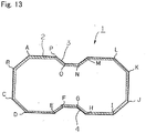
- a crash box 1 in Patent Literature 6 Referring to the cross section of FIG. 13 , at least a part of the cross-sectional shape in an axial direction is a closed cross section having a generally polygonal shape, and there is no flange in the outer side of the closed cross section.
- Trench portions 3 and 4 extending in an axial direction of the tubular main body 2 are provided in a part of the area of a pair of sides D-I and L-A of a basic cross section defined as a polygon A-B-C-D-I-J-K-L-A having a maximum area out of polygons obtained by straightly linking a part of end points A to P of the approximate polygon, by forming an inwardly convex shape on the basic cross section A-B-C-D-I-J-K-L-A in a position other than the end points D, I, L, and A.
- the crash box 1 it is possible to obtain a high impact energy absorption amount by stably generating buckling and plastic deformation in a bellows shape against an impact load exerted in an axial direction without increasing a weight by adding a partitioning wall or increasing a sheet thickness, or generating bending in an axial direction.
- an impact load caused by the crash is not always input in the axial direction of the crash box 1 continuously from the start to the end of plastic buckling deformation of the crash box 1 in a bellows shape. Instead, in many cases, the impact load is exerted obliquely with respect to the axial direction of the crash box 1.
- the crash box 1 stably and reliably generates plastic buckling deformation in a bellows shape across the entire area in the axial direction against an impact load exerted in the axial direction of the main body 2, an impact load exerted obliquely with respect to the axial direction easily generates strong bending deformation in the entire main body 2 in the middle of the plastic buckling deformation of a bellows shape due to a bending moment generated in the main body 2. Then, it is difficult to generate plastic buckling deformation in a bellows shape. Therefore, the impact energy absorption performance is degraded accordingly.
- the crash box 5 includes a tubular main body 10 having a pair of corner portions 6 and 7 arranged oppositely and another pair of corner portions 8 and 9 arranged perpendicularly to a line L1 obtained by linking the corner portions 6 and 7.
- the tubular body 10 has a quadrangular cross-sectional shape having no flange in the outer side.
- an angle ⁇ 1 of the pair of corner portions 6 and 7 is set to 90° or larger and 150° or smaller
- an angle of the another pair of corner portions 8 and 9 is set to 30° or larger and 90° or smaller.
- the cross-sectional shape of the crash box 5 has one or more inwardly convex trench portions 11 to 14 that extend in a longitudinal direction in a position other than the pair of corner portions 6 and 7 and the another pair of corner portions 8 and 9, is symmetrical with respect to a line passing through the pair of corner portions 6 and 7, and is provided in each of at least one out of two pairs of sides arranged symmetrically with respect to the line L1 passing through the pair of corner portions 6 and 7.
- each of the sides satisfies a relationship "5 ⁇ (W-N ⁇ Wc)/(N+1)/t ⁇ 50", where "t” denotes a sheet thickness (mm), “W” denotes a length of the side (mm), “N” denotes the number of trench portions 11 to 14, and “Wc” denotes an average of opening widths of the N trench portions (mm).
- the crash box 15 has a pair of corner portions 16 and 17 arranged oppositely and another pair of corner portions 18 and 19 arranged to intersect with a line obtained by linking the pair of corner portions 16 and 17 at an angle of 80° to 100°.
- the crash box 15 is formed from a metal tubular body 20 having a quadrangular basic cross-sectional shape, so that an impact load is exerted from one end to the other end in an axial direction of the tubular body 20.
- an angle of the pair of corner portions 16 and 17 is set to 90° or larger and 150° or smaller, and an angle of the another pair of corner portions 18 and 19 is set to 30° or larger and 90° or smaller.
- the crash box 15 has one or more inwardly convex trench portions 21 to 24 extending in a longitudinal direction in a position other than the pair of corner portions 16 and 17 and the another pair of corner portions 18 and 19. Furthermore, a cross-sectional peripheral length of the tubular body 20 in one end side is shorter than a cross-sectional peripheral length of the tubular body 20 in the other end side.
- the crash box 15 it is possible to continuously and stably generate plastic buckling deformation in a bellows shape even when an impact load caused by a crash is exerted obliquely as well as in a direction parallel to the axis direction. As a result, the crash box 15 has an excellent impact absorption characteristic (herein, referred to as "robustness"), that is, a large absorption amount of impact absorption energy even for an oblique crash.
- robustness an excellent impact absorption characteristic
- crushing of the tubular body 20 reliably progresses from the impact end side when an impact force is exerted to the tubular body 20. Even when an impact load caused by a crash is exerted obliquely from an axial direction of the tubular body 20, crushing of the tubular body 20 propagates from one end where the impact load is exerted to the other end in the axial direction of the tubular body 20, so that the tubular body 20 can reliably and effectively buckled and deformed in a bellows shape to absorb impact energy.
- Patent Literature 9 discloses a further side member
- Patent Literature 10 discloses a bumper and a shock absorbing structure of a vehicle.
- Patent literature 8 discloses a crash box according to the preamble of claim 1.
- An object of this invention is to provide a crash box having robustness higher than that disclosed in Patent Literature 8 and an automobile chassis installed with the crash box.
- This invention has been achieved based on a technical concept that, in the crash box disclosed in Patent Literature 8, robustness can be further improved compared to the crash box disclosed in Patent Literature 8 by forming opposite slope surfaces of the trench portion at different heights (length of the oblique side on the cross section) and forming all of the sides on the cross section in one end (impact load exerting portion) of the tubular body to be parallel to the opposite side on the cross section in the other end of the tubular body.
- a crash box including a metal tubular body of a quadrangular basic cross-sectional shape having a pair of corner portions arranged oppositely and another pair of corner portions arranged to intersect at an angle of 80° or larger and 100° or smaller with respect to a line obtained by linking the pair of corner portions to receive an impact load from one end to the other end in an axial direction of the tubular body, wherein, on the cross section of the tubular body, (i) an angle ⁇ of the pair of corner portions is set to 90° or larger and 150° or smaller, an angle ⁇ of the another pair of corner portions is set to 30° or larger and 90° or smaller, (ii) one or more inwardly convex trench portions extending in a longitudinal direction are provided in each of a pair of sides interposing at least either one of the pair of corner portions, (iii) a cross-sectional peripheral length of the tubular body in the one end side is shorter than a cross-sectional peripheral length of the tubular body in the other end side, (iv) an aspect ratio
- an automobile chassis having one or two pair (s) of crash boxes arranged symmetrically with respect to a vehicle width center in a width direction of front or rear portion of the chassis.
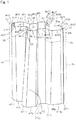
- FIG. 1 is a perspective view illustrating an exemplary shape of a crash box 30 according to an embodiment of this invention.
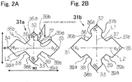
- FIG. 2A is an explanatory diagram illustrating an exemplary cross-sectional shape of one end (impact end) 31a of the crash box 30 according to an embodiment of this invention.
- FIG. 2B is an explanatory diagram illustrating an exemplary cross-sectional shape of the other end (anti-impact end) 31b of the crash box 30 according to an embodiment of this invention.
- FIG. 1 shows a case where the crash box 30 has bonding surfaces 40a, 41a, 40b, and 41b
- a contour of the crash box 30 that does not have the bonding surfaces 40a, 41a, 40b, and 41b is also illustrated together as a dotted line.
- the crash box 30 has a metal tubular body 31.
- the crash box 30 may be formed only by the tubular body 31, or a mount plate bonded for installation to a bumper reinforcement or a side member may be provided in one or both ends of the tubular body 31. Using the mount plate, the crash box 30 can be detachably installed.
- the bumper reinforcement is bonded to one end 31a of the crash box using a suitable means such as welding.
- the other end 31b is preferably detachably installed in the side member, which is a part of the body shell of the automobile chassis, directly or indirectly using the mount plate.
- the crash box 30 receives an impact load from the one end 31a to the other end 31b in an axial direction of the tubular body 31 by interposing the bumper reinforcement.
- the tubular body 31 has a rectangular basic cross-sectional shape.
- the "basic cross-sectional shape” of this invention refers to a rectangular cross-sectional shape that forms a contour excluding an inwardly convex trench portion on the cross section of the tubular body 31.
- the basic cross-sectional shape refers to a quadrangle defined by corner portions 32 to 35, for example, as illustrated in FIGS. 2A and 2B .
- the "basic cross-sectional shape” refers to a virtual quadrangle defined by four sides and four intersection points of a quadrangle that forms a contour of the tubular body.
- the basic cross-sectional shape includes a pair of corner portions 32 and 33 arranged oppositely and another pair of corner portions 34 and 35 arranged to intersect at an angle of 80° or larger and 100° or smaller with respect to a virtual line L1 obtained by linking the pair of corner portions 32 and 33 with each other.
- the intersecting angle is preferably set to 85° or larger and 95° or smaller, and more preferably, they are generally perpendicular to each other.
- the crash box 30 has a quadrangular basic cross-sectional shape in which the corner portions 32 to 35 corresponding to ridge portions having high rigidity and forming a contour of the cross-sectional shape are arranged in a direction linking the pair of corner portions 32 and 33 and a direction linking the another pair of corner portions 34 and 35.
- the line linking the pair of corner portions 32 and 33 and the line linking the another pair of corner portions 34 and 35 are generally perpendicular to each other according to a preferable embodiment of this invention as described above.
- the intersecting angle may be set to 80° or larger and 100° or smaller, and more preferably, 85° or larger and 95° or smaller.
- a cross section of the polygon as a cross-sectional shape of the crash box 30 which is the tubular body 31 includes edges serving as ridge portions of the tubular body 31 and sides which are plane portions between the ridge portions of the tubular body 31. If a load is exerted to this cross section in an axial direction of the tubular body 31, the ridge portion and the plane portion generate out-of-plane deformation (deformation toward the outside of the closed cross section).
- the ridge portion having high rigidity is subjected to out-of-plane deformation relatively weaker than that of the plane portion having lower rigidity and generates a compressive strain. Then, as the exerted load increases, the amount of out-of-plane deformation in the ridge portion increases, so that the ridge portion is finally buckled and bent to generate plastic buckling deformation. As such a series of deformation is repeated several times, the crash box 30 is plastically buckled and deformed in a bellows shape and is crushed along an axial direction so as to absorb impact energy.
- Such a series of deformation behaviors changes depending on a direction of the exerted load. For example, when the load is exerted obliquely with respect to the axial direction of the crash box 30, the amount of out-of-plane deformation in the ridge portion increases, and the compressive strain is reduced, compared to a case where the load is exerted in the axial direction.
- the compressive strain generated in the ridge portion decreases gradually and generates strong out-of-plane deformation, so that the ridge portion is crooked with a large radius of curvature, and the entire crash box 30 is bent.
- the crash box 30 is easily bent.
- the tubular body 31 plastically buckled and deformed several times, and the impact absorption energy is determined by a load hysteresis generated in that case. That is, the number of plastic buckling deformation generated in series determines an impact energy absorption amount.
- the buckling wrinkle generated by the buckling deformation in the ridge portion propagates to the plane portion, and buckling wrinkle is generated in the plane portion. Then, the buckling wrinkle generated in the plane portion is repeated, so that the next (n+1) th buckling deformation is generated in another portion of the axial direction.
- An interval from generation of the (n)th buckling to generation of the (n+1)th buckling, that is, a buckling wavelength is influenced by a wrinkle size generated by buckling of the ridge portion caused by the deformation described above.
- the wrinkle size is dominated by the out-of-plane deformation generated in the plane portion. Therefore, in order to improve impact energy absorption performance using a plastic buckling behavior having a short buckling wavelength, it is effective to reduce out-of-plane deformation generated in the plane portion.
- the cross-sectional shape of the tubular body 31 has a shape generally symmetrical to either one of a virtual line L1 passing though the pair of corner portions 32 and 33 and a virtual line L2 passing through the another pair of corner portions 34 and 35.
- the tubular body 31 is formed of a metal material and has a cross-sectional shape having a quadrangular basic cross-sectional shape defined by the corner portions 32 to 35.
- a common steel product or a high-tensile steel product may be used as the metal material, the invention is not limited thereto.
- the metal material may be suitably selected depending on specifications required as a crash box 30.
- the basic cross-sectional shape of the crash box 30 preferably has a shape generally symmetrical to the virtual line L1 passing through the pair of corner portions 32 and 33.
- the basic cross-sectional shape preferably has a shape generally symmetrical to the virtual line L2 passing through the another pair of corner portions 34 and 35. This is because performance against an oblique load from various exertion directions is improved as the symmetry is improved.
- An angle ⁇ 1 of the inner corner between the pair of corner portions 32 and 33 is set to 90° or larger and 150° or smaller.
- An angle ⁇ 2 of the inner corner between the another pair of corner portions 34 and 35 is set to 30° or larger and 90° or smaller. The reason will be described.
- the rigidity of the corner portions 32 to 35 corresponding to the ridge portions is determined by an arc length of the ridge portion.
- an angle ⁇ 1 of the inner corner between the pair of corner portions 32 and 33 is set to 90° or larger and 150° or smaller.
- the angle ⁇ 1 exceeds 150°, the arc length of the corner portions 32 and 33 is significantly shortened when the radius of curvature of the corner round portion is set to a realistic value (1.5 mm or larger and 10.0 mm or smaller) determined in consideration of a manufacturing and design space of the crash box. Therefore, it is difficult to guarantee rigidity as desired and generate the plastic buckling deformation as desired.
- the angle ⁇ 2 of the inner corner between the another pair of corner portions 34 and 35 is associated with the angle ⁇ 1 of the inner corner between the pair of corner portions 32 and 33. Therefore, if the angle ⁇ 1 is set to 90° or larger and 150° or smaller, the angle ⁇ 2 is set to 30° or larger and 90° or smaller.
- the angle ⁇ 1 is set to 90° or larger and 120° or smaller
- the angle ⁇ 2 is set to 60° or larger and 90° or smaller.
- the angle ⁇ 1 between the pair of corner portions 32 and 33 be larger than the angle ⁇ 2 between the another pair of corner portions 34 and 35.
- This crash box 30 has a cross-sectional shape capable of increasing a burden of the oblique load in the corner portions 32 to 35 corresponding to ridge portions having high rigidity, that is, the corner portions 32 to 35 are arranged in an oblique load exertion direction.
- the cross-sectional shape since the cross-sectional shape has the corner portions 32 to 35, it is possible to alleviate out-of-plane deformation generated by the load exerted in an oblique direction and increase a compressive strain for the corner portions 32 to 35.
- the tubular body 31 is provided with one or more inwardly convex trench portions 36, 37, 38, and 39 (in this embodiment, a trench portion is formed for each of four sides) extending in a longitudinal direction in each of a pair of sides interposing at least one of the pair of corner portions 32 and 33.
- the trench portions 36 to 39 are preferably provided in all of the four sides. However, the trench portion may be provided in only two sides interposing at least one of the pair of corner portions 32 and 33. In addition, it is preferable that the trench portions 36 to 39 be provided in positions other than the pair of corner portions 32 and 33 and the another pair of corner portions 34 and 35 in order to reliably crush the crash box in a bellows shape and generate plastic deformation when an impact load is exerted to the tubular body 31.
- the trench portions 36 to 39 will be described.
- the trench portions 36 to 39 satisfy the following formula (1), and preferably, the following formula (1'): 5 ⁇ W ⁇ N ⁇ Wc / N + 1 / t ⁇ 50 and 5 ⁇ W ⁇ N ⁇ Wc / N + 1 / t ⁇ 30
- t denotes a sheet thickness (mm)
- W denotes a length of each side (mm)
- N denotes the number of trench portions 36 to 39
- Wc denotes an average of the opening widths of the N trench portions 36 to 39 (mm), in each side of a quadrangle which is a basic cross-sectional shape.
- the shape of the crash box 30 after buckling can have a bellows shape with a short wavelength by generating plastic buckling deformation, and high absorption performance of the impact absorption energy is obtained. Now, the reason will be described.
- the buckling wavelength closely relates to out-of-plane deformation (displacement) generated by an impact load on the cross section of the tubular body 31 of the crash box 30. As the amount of out-of-plane deformation increases, the buckling wavelength increases. Meanwhile, as the out-of-plane deformation decreases, the buckling wavelength decreases.
- a distance W between the corner portions 32 to 35 is set to be smaller than 50 times of the sheet thickness t of the tubular body 31. That is, in this crash box 30, if there is a side where no trench portions 36 to 39 are provided, the sheet thickness t (mm) and the length W (mm) of the side satisfy the following formula (2): 5 ⁇ W / t ⁇ 50
- the trench portions 36 to 39 are provided in each side, so as to divide the length of the plane portion.
- the sides excluding the trench portions 36 to 39 satisfy the aforementioned formula (2).
- the plane portion may be divided to smaller pieces by providing the trench portions 36 to 39 in the plane portion.
- the trench portions 36 to 39 be provided in a position where bending deformation of the entire crash box is suppressed when an oblique load is exerted, and there is no corner portion 32 to 35 serving as a start point of the plastic buckling deformation due to its load.
- trench portions 36 to 39 are provided in the plane portion to form a new ridge portion by the trench portions 36 to 39, so that a width of the plane portion is controlled within a range where a short buckling wavelength can be obtained.
- each side satisfy the following relationships: 5 ⁇ W ⁇ N ⁇ Wc / N + 1 / t ⁇ 50 , and 5 ⁇ W ⁇ N ⁇ Wc / N + 1 / t ⁇ 30 , where "t” denotes a sheet thickness (mm), “W” denotes a length of the side (mm), “N” denotes the number of the trench portions 36 to 39, and “Wc” denotes an average of the opening widths of the N trench portions 36 to 39, in each side.
- the depth dc of the trench portions 36 to 39 exceed 10 mm.
- each corner portion 32 to 35 be larger than any radius of curvature Rc of the angled portion of the trench portions 36 to 39. The reason will be described.
- a geometrical moment of inertia of a thin circle is dominated by a diameter and a thickness. As the diameter increases, the geometrical moment of inertia increases. Similarly, a modulus of section affecting the bending strength also increases as the diameter increases. That is, in order to suppress bending deformation for a bending moment generated when an oblique load is exerted to the crash box 30, it is effective to set a high geometrical moment of inertia for the corner portions 32 to 35 positioned in a contour of the cross section to support the exerted load. In addition, if the radius of curvature of the angled portion of each trench portion 36 to 39 increases, a deformation resistance excessively increases in the trench portions 36 to 39, so that it is difficult to generate plastic buckling deformation in this area.
- the radius of curvature R of each corner portion 32 to 35 that dominates the bending strength of the entire crash box 30 be larger than the radius of curvature Rc of the angled portion of each trench portion 36 to 39.
- a cross-sectional peripheral length (outer peripheral length of the tubular body 31 in FIG. 2A ) of the tubular body 31 in the one end 31a side of the tubular body 31 is smaller than a cross-sectional peripheral length (outer peripheral length of the tubular body 31 in FIG. 2B ) of the tubular body 31 in the other end 31b side.
- the cross-sectional peripheral length of the tubular body 31 monotonically increases from the one end 31a to the other end 31b with a constant ratio. As a result, as an impact load is exerted to the tubular body 31, crushing starts from the one end 31a side. In this case, the ridge line obtained by linking the ends 31a and 31b has a straight shape.
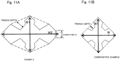
- an aspect ratio which is a ratio between a length W2 of the longest diagonal line and a length of the shortest diagonal line out of diagonal lines of a polygon serving as a basic cross-sectional shape changes in a position along the axial direction of the tubular body 31.
- oblique sides (36a and 36b) of the trench portion 36 in FIGS. 2A and 2B have different lengths.
- the oblique sides (37a and 37b) of the trench portion 37 have different lengths, and the oblique sides (38a and 38b) of the trench portion 38 have different lengths.
- the oblique sides (39a and 39b) of the trench portion 39 have different lengths.
- a difference between the angle ⁇ 1 of the pair of corner portions 32 and 33 and the angle ⁇ 2 of the another pair of corner portions 34 and 35 increases or decreases from the one end 31a to the other end 31b.
- the tubular body 31 may be obtained by bonding a first steel sheet 40 and a second steel sheet 41 using a proper means (such as laser welding or spot welding).
- bonding surfaces 40a, 41a, 40b, and 41b formed in a plane shape for bonding the first and second steel sheets 40 and 41 may be provided in the vicinity of the another pair of corner portions 34 and 35 corresponding to each end of the first and second steel sheets 40 and 41.
- the another pair of corner portions 34 and 35 serves as virtual points of the tubular body 31.
- the tubular body 31 be formed by assembling two components obtained by bending a thin sheet using a proper means such as welding or bonding.
- the tubular material may be integratedly designed using various methods such as hydroforming or extrusion.
- the crash box 30 includes plane bonding surfaces 40a, 41a, 40b, and 41b and is formed by bonding the first and second steel sheets 40 and 41 by overlappingly bonding the bonding surfaces 40a, 41a, 40b, and 41b.
- the width W' of the bonding surfaces 40a, 41a, 40b, and 41b is set to be greater than 5 times and smaller than 50 times, and preferably smaller than 30 times, of the sheet thickness t of the tubular body 31 of the crash box 30.
- the length W (mm) of the side in the Formulas (1), (1'), and (2) refers to a length of the side after being reduced by forming the bonding surfaces 40a, 41a, 40b, and 41b.
- the plastic buckling deformation is more stably generated.
- such an effect is insignificant if the ratio (W'/t) between the width (length) W' of the bonding surfaces 40a, 41a, 40b, and 41b and the sheet thickness t is equal to or smaller than 5 times. Meanwhile, if the ratio (W'/t) is equal to or greater than 50 times, the buckling wavelength increases, and the impact energy absorption effect is reduced.
- the bonding surfaces 40a, 41a, 40b, and 41b are located in an overlapping bonding portion of an edge of a single steel sheet or overlapping bonding portions of a plurality of steel sheets, the bending rigidity of the tubular body 31 is improved when an oblique impact load is exerted. As a result, it is possible to suppress generation of bending deformation in the entire tubular body 31 in the middle of plastic buckling deformation in a bellows shape.
- the bonding of the overlapping bonding portion is performed through consecutive bonding such as structural adhesive bonding or consecutive welding such as laser welding, it is possible to further improve bending rigidity of the tubular body 31, compared to an intermittent bonding such as spot welding. Therefore, the consecutive bonding is preferable.
- a material of the tubular body 31 is not limited to the steel sheet.
- a non-ferrous metal material such as aluminum alloy or a non-metal material such as resin may also be used.
- the entire tubular body 31 in the one end 31a side serving as an impact end is shorter than that of the other end 31b side, it is possible to reliably generate crushing from the one end 31a side and improve stability of the impact absorbing performance during a crash. For this reason, it is preferable that the entire tubular body 31 be formed in a tapered shape along the axial direction.
- a dimension of the angled portion of the tubular body 31 is set such that a difference between the angle ⁇ 1 of the pair of corner portions 32 and 33 and the angle ⁇ 2 of the another pair of corner portions 34 and 35 increases from one end 31a to the other end 31b for an impact load directly input from the front bumper reinforcement, and the cross-sectional peripheral length of the tubular body 31 (herein, the "cross-sectional peripheral length" refers to a peripheral length on the cross section of the tubular body) in the one end 31a side is shorter than the cross-sectional peripheral length of the tubular body 31 in the other end 31b side.
- the cross-sectional peripheral length of the tubular body 31 monotonically increases from the one end 31a side to the other end 31b side with a constant ratio.
- the invention is not limited thereto.
- the cross-sectional peripheral length of the tubular body 31 may increase or decrease between the one end 31a and the other end 31b. The effect of the invention is not harmed even in this case. That is, the cross-sectional peripheral length in the one end 31a may be smaller than the cross-sectional peripheral length of the other end 31b.
- the cross-sectional peripheral length of the tubular body 31 may increase or decrease between one end and the other end as described below.
- a cross section in the vicinity of the impact end corresponding to the one end is abruptly reduced so as to facilitate deformation at the start of a crash.
- the cross-sectional shape may be constant.
- a ratio of the cross-sectional peripheral length defined as "(cross-sectional peripheral length of one end 31a) / (cross-sectional peripheral length of the other end 31b)" be set to 0.6 or greater or 0.9 or smaller. If the ratio of the cross-sectional peripheral length is smaller than 0.6, the initial load after starting a crash excessively decreases, so that the energy absorption performance in the initial stage of the crash is degraded. Meanwhile, if the ratio of the cross-sectional peripheral length exceeds 0.9, the effect of the invention, that is, stable buckling by suppressing bending deformation in the case of an oblique impact is degraded, and bending may easily be generated.
- an increase of the cross-sectional peripheral length of the tubular body 31 is vertically symmetrical as seen from the side of the chassis.
- an increase of the cross-sectional peripheral length is not limited thereto.
- a degree of the increase of the cross-sectional peripheral length in the area over a horizontal plane passing through a center of the tubular body 31 may be different from a degree of the increase of the cross-sectional peripheral length in the area under the horizontal plane.
- the cross-sectional peripheral length of the tubular body 31 in the one end 31a side is shorter than the cross-sectional peripheral length of the tubular body 31 in the other end 31b side, crushing reliably progresses from the one end 31a to the other end 31b as an impact load is input to the one end 31a from the front bumper reinforcement. Finally, it is possible to buckle and deform the tubular body 31 in a bellows shape and effectively absorb impact energy.
- the tubular body 31 preferably has a tapered shape of which cross section does not have a similar shape across the entire cross section in the axial direction, but changes to a certain direction. Specifically, by changing the flatness along the axial direction, it is possible to obtain sufficient robustness against the oblique load.
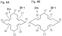
- FIG. 4A is an explanatory diagram illustrating an exemplary cross-sectional shape of one end (impact end) 31a of a crash box 30-1 according to another embodiment of this invention.
- FIG. 4B is an explanatory diagram illustrating an exemplary cross-sectional shape of the other end (anti-impact end) 31b of the crash box 30-1 according to another embodiment of this invention.
- the shape of the one end 31a becomes flatter.
- the one having a shorter length out of the pair of corner portions 32 and 33 and the another pair of corner portions 34 and 35 has rigidity lower than that of the other one having a longer length. Therefore, while the one having higher rigidity suppresses an early collapse of the tubular body 31 that receives an impact load, the other one having lower rigidity serves as a start point so that crushing can easily start from the one end 31a.
- the one end 31a side is designed to be lower than the flatness of the other end 31b side, the one end 31a side is approximated to a square shape, compared to the other end 31b side. Therefore, robustness in the impact load exertion direction is improved.
- Which of the one end 31a or the other end 31b has higher flatness may be appropriately selected depending on utilization of the crash box, required performance, and the like.
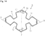
- FIG. 5 is an explanatory diagram illustrating that a crash box does not work when opposite slope surfaces (36a and 36b), (37a and 37b), (38a and 38b), and (39a and 39b) of the trench portions 36 to 39, respectively, have the same height.
- the shape of the tubular body 31 in the one end 31a is denoted by a dotted line
- the shape of the tubular body 31 in the other end 31b is denoted by a solid line.
- the flatness of the one end 31a serving as an impact end is higher than the flatness of the other end 31b.
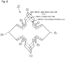
- FIG. 6 is an explanatory diagram collectively illustrating cross-sectional shapes of the one end 31a (impact end), the middle, and the other end 31b (anti-impact end) in an exemplary crash box 30 in which the flatness is higher in the one end 31a.
- FIG. 7 is an explanatory diagram collectively illustrating cross-sectional shapes of the one end 31a (impact end), the middle, and the other end 31b (anti-impact end) in an exemplary crash box 30 in which the flatness is lower in the one end 31a.
- the opposite slope surfaces (36a and 36b), (37a and 37b), (38a and 38b), and (39a and 39b) of the trench portions 36 to 39, respectively, have different heights (the length of the oblique side on the cross section). This is because, when the slope surfaces (36a and 36b), (37a and 37b), (38a and 38b), and (39a and 39b) have the same height, and the flatnesses of the one end 31a as an impact end and the other end 31b as an anti-impact end change as illustrated in FIG. 5 , tilting is inevitably generated in the tubular body 31, so that the manufacturing of the tubular body 31 becomes difficult.
- the ridge lines 42 to 45 (refer to FIG. 1 ) of the tubular body 31 including each of the corner portions 32 to 35 may be tilted, it is not suitable for a crash box that requires robustness.
- the opposite slope surfaces (36a and 36b), (37a and 37b), (38a and 38b), and (39a and 39b) of the trench portions 36 to 39, respectively have different heights (the length of the oblique side on the cross section) as illustrated in FIGS. 1 to 4 , 6 , and 7 , it is possible to design the crash box such that overall sides 46-1 to 46-22 included in the cross section in the one end 31a and the opposite sides 47-1 to 47-22 included in the cross section of the other end 31b are in a parallel relationship without having tilting.
- the crash box 30 is configured as described above.
- the crash box is preferably installed in the automobile chassis such that one or two pairs are arranged with respect to the vehicle width center along a width direction of the front or rear side of the automobile chassis.
- the crash box 30 is formed from a metal tubular body 31 having a closed cross-sectional shape of which the entire length is set to, generally, 80 mm or longer and 300 mm or shorter.
- the crash box 30 is bonded to a bumper reinforcement using a proper means such as welding so as to be detachably installed in the area set in ends of the left and right side members that support the bumper reinforcement by interposing a mount plate. Similar to a normal case, a total of two crash boxes 30 are arranged in the bumper reinforcement in the vehicle width direction to face the front-rear direction of the chassis.
- the crash box 30 according to this invention is preferably arranged such that the virtual line L1 obtained by linking the pair of corner portions 32 and 33 is directed in an approximately vertical or horizontal direction.
- the crash box 30 is crushed by generating plastic buckling deformation in a bellows shape ahead of the side member included in the body shell from an impact load input to the bumper reinforcement to absorb the impact energy.
- it is possible to reduce a repair cost by protecting damage to the body shell in a light collision and protect passengers by effectively absorbing the impact energy along with the side member.
- the trench portion is provided in each of the four basic sides 36 to 39 of the cross section.
- the trench portion may be provided only in a pair of sides (36 and 37), (38 and 39), (36 and 38), or (37 and 39) interposing any one of the corner portions 32 to 35.
- FIG. 8 illustrates a crash box 140 having a cross section when a trench portion is provided in a pair of sides (36 and 37) interposing a single corner portion 32, in which the flatness is higher in the impact end side.
- FIG. 9 illustrates a crash box 141 having a cross section when a trench portion is provided in a pair of sides (36 and 37) interposing a single corner portion 32, in which the flatness is lower in the impact end side.
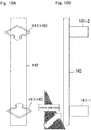
- FIG. 10A is a front view when the crash box 141 is installed in the bumper reinforcement 142.
- FIG. 10B is a top plan view when the crash box 141 is installed in the bumper reinforcement 142.
- the crash boxes 140 and 141 having cross sections of FIGS. 8 and 9 are installed in the bumper reinforcement 142 as illustrated in FIGS. 10A and 10B .
- the crash box 141-1 is installed in the left side of the bumper reinforcement 142
- the crash box 141-2 is installed in the right side of the bumper reinforcement 142.
- crash box according to this invention was evaluated by performing a numerical analysis.
- the crash box 30 having the shape of FIGS. 1 , 2 , and 6 is fixed on a floor surface with an inclination of 15°, and a rigid wall was crashed in the axial direction of the crash box 30 at a speed of 16 km/h, so that an analysis was performed by crushing the crash box 30 in the axial direction by 150 mm to examine a plastic buckling behavior of the crash box 30.
- Comparative Example 2 corresponds to Example 4 discussed in the example of Patent Literature 8 considered by the inventors.
- FIG. 11 and Table 1 show a shape of the crash box in this Example and Comparative Examples 1 and 2.
- FIG. 12 shows a crushing state of the crash box when a crushing stroke is set to 0 mm, 50 mm, 100 mm, and 150 mm in Example 1 and Comparative Examples 1 and 2.
- Table 1 shows a crushing load ratio F1/F2 between an average crushing load F1 under a pressing length 40 mm to 60 mm where deformation at the start of crushing is stabilized and an average crushing load F2 under a pressing length 120 mm to 140 mm.
Landscapes
- Engineering & Computer Science (AREA)
- Mechanical Engineering (AREA)
- General Engineering & Computer Science (AREA)
- Vibration Dampers (AREA)
- Body Structure For Vehicles (AREA)
Claims (10)
- Crashbox (30) mit einem Metallhohlkörper (31) mit einer vierseitigen Grundquerschnittsform, die ein Paar von gegenüberliegenden Eckabschnitten (32, 33) und ein anderes Paar von Eckabschnitten (34, 35), die angeordnet sind, um sich unter einem Winkel von 80° oder größer und 100° oder kleiner bezogen auf eine Linie, die durch Verbinden des Paars von Eckabschnitten (32, 33) erhalten wird, zu schneiden, aufweist, um eine Stoßlast von einem Ende zu dem anderen Ende in einer axialen Richtung des Hohlkörpers aufzunehmen,
wobei, auf einem Querschnitt des Grundkörpers,
ein Winkel (ϑ1) des Paars von Eckabschnitten (32, 33) auf 90° oder größer und 150° oder kleiner gesetzt ist,
ein Winkel (ϑ2) des andern Paars von Eckabschnitten (34, 35) auf 30° oder größer und 90° oder kleiner gesetzt ist,
eine oder mehr nach innen konvexe Grabenabschnitte (36-39), die sich in einer Längsrichtung erstrecken, in jeder von einem Paar von Seiten (36, 37; 38, 39), die mindestens einen von dem Paar von Eckabschnitten (32; 33) einschließen, vorgesehen sind,
eine Querschnittsumfangslänge des Hohlkörpers in der einen Endseite (31a) kürzer ist als eine Querschnittsumfangslänge des Hohlkörpers in der anderen Endseite (31b),
ein Formfaktor zwischen der längsten und der kürzesten von diagonalen Linien eines Polygons der Basisquerschnittsform sich abhängig von einer Position auf der axialen Richtung des Hohlkörpers ändert dadurch gekennzeichnet, dass
gegenüberliegende Neigungsflächen der Grabenabschnitte (36-39) unterschiedliche Höhen aufweisen, die durch die Länge einer schiefen Seite (36a, 36b; 37a, 37b; 38a, 38b; 39a, 39b) auf dem Querschnitt bestimmt werden, so dass Gesamtseiten (46-1 - 46-22) auf dem Querschnitt in dem einen Ende parallel zu den gegenüberliegenden Seiten (47-1 - 47-22) auf dem Querschnitt in dem anderen Ende geformt sind. - Crashbox nach Anspruch 1, wobei die Querschnittsform eine ungefähr symmetrische Form bezogen auf mindestens eine aus einer Linie (L1, L2), die durch das Paar von Eckabschnitten (32, 33) verläuft, und einer Linie, die durch das andere Paar von Eckabschnitten (34,35) verläuft, aufweist.
- Crashbox nach Anspruch 1 oder 2, wobei ein Unterschied zwischen dem Winkel (ϑ1) des Paars von Eckabschnitten (32, 33) und dem ein Winkel (ϑ2) des andern Paars von Eckabschnitten von dem einen Ende (31a) zu dem anderen Ende (31b) zunimmt.
- Crashbox nach Anspruch 1 oder 2, wobei ein Unterschied zwischen dem Winkel (ϑ1) des Paars von Eckabschnitten (32, 33) und dem ein Winkel (ϑ2) des ändern Paars von Eckabschnitten von dem einen Ende (31a) zu dem anderen Ende (31b) abnimmt.
- Crashbox nach einem der Ansprüche 1 bis 4, wobei ein entsprechender von den Grabenabschnitten (36-39) in allen vier Seiten bereitgestellt ist.
- Crashbox nach einem der Ansprüche 1 bis 5, wobei ein Gebiet, das zu mindestens einen Eckabschnitt (32-35) aufweist, eine ebene Verbindungsfläche aufweist.
- Crashbox nach einem der Ansprüche 1 bis 6, wobei eine Querschnittsumfangslänge des Hohlkörpers von dem einen Ende (31a) zu dem anderen Ende (31b) monoton ansteigt.
- Crashbox nach einem der Ansprüche 1 bis 7, wobei der Grabenabschnitt in einer anderen Position als das Paar von Eckabschnitten (32, 33) und das andere Paar von Eckabschnitten (34, 35) vorgesehen ist.
- Automobilchassis mit der Crashbox nach einem der Ansprüche 1 bis 8, wobei ein oder zwei Paar von Crashboxen bezogen auf eine Fahrzeugbreitenmitte in einer Breitenrichtung in einem vorderen oder hinteren Abschnitt des Chassis symmetrisch angeordnet sind.
- Automobilchassis mit der Crashbox nach Anspruch 9, wobei die Crashbox so angeordnet ist, dass eine Linie, die durch Verbinden des Paars von Eckabschnitten erhalten wird, entlang einer ungefähr vertikalen oder horizontalen Richtung gerichtet ist.
Applications Claiming Priority (2)
| Application Number | Priority Date | Filing Date | Title |
|---|---|---|---|
| JP2012182490 | 2012-08-21 | ||
| PCT/JP2013/071979 WO2014030592A1 (ja) | 2012-08-21 | 2013-08-15 | クラッシュボックス及び自動車車体 |
Publications (3)
| Publication Number | Publication Date |
|---|---|
| EP2889188A1 EP2889188A1 (de) | 2015-07-01 |
| EP2889188A4 EP2889188A4 (de) | 2016-04-13 |
| EP2889188B1 true EP2889188B1 (de) | 2017-03-22 |
Family
ID=50149901
Family Applications (1)
| Application Number | Title | Priority Date | Filing Date |
|---|---|---|---|
| EP13830445.6A Active EP2889188B1 (de) | 2012-08-21 | 2013-08-15 | Nicht synchronisiertes getriebe und automobilkarosserie |
Country Status (10)
| Country | Link |
|---|---|
| US (1) | US9463758B2 (de) |
| EP (1) | EP2889188B1 (de) |
| JP (1) | JP5949925B2 (de) |
| KR (1) | KR101685857B1 (de) |
| CN (1) | CN104583020B (de) |
| BR (1) | BR112015003445A2 (de) |
| CA (1) | CA2882393C (de) |
| IN (1) | IN2015DN01802A (de) |
| MX (1) | MX351612B (de) |
| WO (1) | WO2014030592A1 (de) |
Families Citing this family (23)
| Publication number | Priority date | Publication date | Assignee | Title |
|---|---|---|---|---|
| US8539737B2 (en) | 2008-09-19 | 2013-09-24 | Ford Global Technologies, Llc | Twelve-cornered strengthening member |
| US9187127B2 (en) | 2008-09-19 | 2015-11-17 | Ford Global Technologies, Llc | Twelve-cornered strengthening member, assemblies including a twelve-cornered strengthening member, and methods of manufacturing and joining the same |
| JP5988893B2 (ja) * | 2013-02-25 | 2016-09-07 | 豊田鉄工株式会社 | 車両用衝撃吸収部材 |
| JP6020497B2 (ja) * | 2014-03-24 | 2016-11-02 | トヨタ自動車株式会社 | 車両のエネルギ吸収構造及びエネルギ吸収部材 |
| JP6039600B2 (ja) * | 2014-03-28 | 2016-12-07 | 富士重工業株式会社 | 衝撃吸収構造 |
| US10315698B2 (en) | 2015-06-24 | 2019-06-11 | Ford Global Technologies, Llc | Sixteen-cornered strengthening member for vehicles |
| JP2017035921A (ja) * | 2015-08-07 | 2017-02-16 | 豊田鉄工株式会社 | バンパリインフォースメント |
| DE102015117005A1 (de) * | 2015-10-06 | 2017-04-06 | Benteler Automobiltechnik Gmbh | Crashbox |
| US9944323B2 (en) | 2015-10-27 | 2018-04-17 | Ford Global Technologies, Llc | Twenty-four-cornered strengthening member for vehicles |
| US9889887B2 (en) | 2016-01-20 | 2018-02-13 | Ford Global Technologies, Llc | Twelve-cornered strengthening member for a vehicle with straight and curved sides and an optimized straight side length to curved side radius ratio |
| US9789906B1 (en) * | 2016-03-23 | 2017-10-17 | Ford Global Technologies, Llc | Twenty-eight-cornered strengthening member for vehicles |
| US10393315B2 (en) | 2016-04-26 | 2019-08-27 | Ford Global Technologies, Llc | Cellular structures with twelve-cornered cells |
| US10704638B2 (en) | 2016-04-26 | 2020-07-07 | Ford Global Technologies, Llc | Cellular structures with twelve-cornered cells |
| US10473177B2 (en) | 2016-08-23 | 2019-11-12 | Ford Global Technologies, Llc | Cellular structures with sixteen-cornered cells |
| US10220881B2 (en) | 2016-08-26 | 2019-03-05 | Ford Global Technologies, Llc | Cellular structures with fourteen-cornered cells |
| US10279842B2 (en) | 2016-08-30 | 2019-05-07 | Ford Global Technologies, Llc | Twenty-eight-cornered strengthening member for vehicles |
| US10300947B2 (en) | 2016-08-30 | 2019-05-28 | Ford Global Technologies, Llc | Twenty-eight-cornered strengthening member for vehicles |
| US10429006B2 (en) | 2016-10-12 | 2019-10-01 | Ford Global Technologies, Llc | Cellular structures with twelve-cornered cells |
| EP3626545A1 (de) | 2018-09-20 | 2020-03-25 | Constellium Singen GmbH | Verbessertes stossfängersystem |
| US11104283B2 (en) * | 2018-11-16 | 2021-08-31 | Aisin Seiki Kabushiki Kaisha | Vehicular energy absorbing member and manufacturing method thereof |
| FR3090212B1 (fr) * | 2018-12-17 | 2022-01-07 | Valeo Systemes Thermiques | Unité d’absorption d’énergie de choc pour dispositif de stockage d'énergie électrique |
| US11292522B2 (en) | 2019-12-04 | 2022-04-05 | Ford Global Technologies, Llc | Splayed front horns for vehicle frames |
| CN111319577B (zh) * | 2020-04-20 | 2024-03-19 | 一汽奔腾轿车有限公司 | 一种液压成形结构吸能盒 |
Family Cites Families (19)
| Publication number | Priority date | Publication date | Assignee | Title |
|---|---|---|---|---|
| KR960013914A (ko) * | 1994-10-04 | 1996-05-22 | 고오사이 아끼오 | 충격흡수 구조체 |
| JPH08108863A (ja) | 1994-10-12 | 1996-04-30 | Honda Motor Co Ltd | 自動車のフロントサイドフレーム構造 |
| JPH08128487A (ja) | 1994-11-02 | 1996-05-21 | Nissan Motor Co Ltd | エネルギ吸収材およびその製造方法 |
| JP3676491B2 (ja) | 1996-04-12 | 2005-07-27 | 新日本製鐵株式会社 | 衝撃吸収部材 |
| JPH1029482A (ja) * | 1996-07-15 | 1998-02-03 | Ootsuka:Kk | 衝撃エネルギー吸収材 |
| BE1010869A3 (fr) * | 1997-01-20 | 1999-02-02 | Cockerill Rech & Dev | Dispositif d'absorption d'energie. |
| JP3988365B2 (ja) * | 2000-08-09 | 2007-10-10 | 三菱ふそうトラック・バス株式会社 | 移動体用緩衝装置 |
| JP3854812B2 (ja) | 2001-03-27 | 2006-12-06 | 新日本製鐵株式会社 | 自動車用強度部材 |
| JP4759871B2 (ja) | 2001-08-02 | 2011-08-31 | Jfeスチール株式会社 | 衝突エネルギー吸収部材 |
| CN100476233C (zh) * | 2003-07-28 | 2009-04-08 | 住友金属工业株式会社 | 碰撞吸收构件 |
| JP2006176093A (ja) * | 2004-12-24 | 2006-07-06 | Aisin Seiki Co Ltd | バンパ及び車両の衝撃吸収構造 |
| JP5147003B2 (ja) * | 2007-03-02 | 2013-02-20 | 新日鐵住金株式会社 | サイドメンバー |
| JP4888259B2 (ja) | 2007-07-10 | 2012-02-29 | セイコーエプソン株式会社 | 流体噴射装置 |
| JP5040568B2 (ja) * | 2007-10-01 | 2012-10-03 | マツダ株式会社 | 自動車の車体構造 |
| JP5330674B2 (ja) * | 2007-11-05 | 2013-10-30 | 豊田鉄工株式会社 | クラッシュボックス |
| JP4450064B2 (ja) * | 2007-12-17 | 2010-04-14 | 日産自動車株式会社 | フェンダープロテクタ構造 |
| JP5126503B2 (ja) * | 2008-02-04 | 2013-01-23 | 新日鐵住金株式会社 | クラッシュボックス及びその車体への取付け構造 |
| JP5488069B2 (ja) * | 2009-08-05 | 2014-05-14 | 新日鐵住金株式会社 | クラッシュボックス及び自動車車体 |
| DE102009056443A1 (de) * | 2009-12-02 | 2011-06-09 | Benteler Automobiltechnik Gmbh | Crashbox und Verfahren zu deren Herstellung |
-
2013
- 2013-08-15 IN IN1802DEN2015 patent/IN2015DN01802A/en unknown
- 2013-08-15 KR KR1020157004900A patent/KR101685857B1/ko active IP Right Grant
- 2013-08-15 MX MX2015002191A patent/MX351612B/es active IP Right Grant
- 2013-08-15 BR BR112015003445A patent/BR112015003445A2/pt not_active Application Discontinuation
- 2013-08-15 US US14/422,244 patent/US9463758B2/en active Active
- 2013-08-15 CN CN201380044012.8A patent/CN104583020B/zh active Active
- 2013-08-15 EP EP13830445.6A patent/EP2889188B1/de active Active
- 2013-08-15 CA CA2882393A patent/CA2882393C/en not_active Expired - Fee Related
- 2013-08-15 WO PCT/JP2013/071979 patent/WO2014030592A1/ja active Application Filing
- 2013-08-15 JP JP2014531607A patent/JP5949925B2/ja active Active
Non-Patent Citations (1)
| Title |
|---|
| None * |
Also Published As
| Publication number | Publication date |
|---|---|
| KR101685857B1 (ko) | 2016-12-12 |
| MX2015002191A (es) | 2015-05-07 |
| EP2889188A4 (de) | 2016-04-13 |
| CA2882393C (en) | 2016-06-28 |
| CA2882393A1 (en) | 2014-02-27 |
| US20150197206A1 (en) | 2015-07-16 |
| IN2015DN01802A (de) | 2015-05-29 |
| MX351612B (es) | 2017-10-18 |
| US9463758B2 (en) | 2016-10-11 |
| KR20150038345A (ko) | 2015-04-08 |
| BR112015003445A2 (pt) | 2017-07-04 |
| JP5949925B2 (ja) | 2016-07-13 |
| CN104583020A (zh) | 2015-04-29 |
| EP2889188A1 (de) | 2015-07-01 |
| CN104583020B (zh) | 2016-10-26 |
| WO2014030592A1 (ja) | 2014-02-27 |
| JPWO2014030592A1 (ja) | 2016-07-28 |
Similar Documents
| Publication | Publication Date | Title |
|---|---|---|
| EP2889188B1 (de) | Nicht synchronisiertes getriebe und automobilkarosserie | |
| JP4371059B2 (ja) | 衝撃吸収部材 | |
| EP1653114B1 (de) | Stossabsorbierendes glied | |
| JP5330674B2 (ja) | クラッシュボックス | |
| JP5488069B2 (ja) | クラッシュボックス及び自動車車体 | |
| JP7135274B2 (ja) | 車両用構造部材 | |
| WO2005010396A1 (ja) | 衝撃吸収部材 | |
| JP2017159896A (ja) | 車両用構造部材 | |
| KR20130126716A (ko) | 금속제 중공 기둥 형상 부재 | |
| JP5147003B2 (ja) | サイドメンバー | |
| WO2013141049A1 (ja) | バンパーリインフォースメント | |
| JP2006207726A (ja) | 衝撃吸収部材 | |
| JP4766422B2 (ja) | クラッシュボックス | |
| JP2011056997A (ja) | 金属製中空柱状部材 | |
| JP5034793B2 (ja) | 衝撃吸収方法 | |
| KR20210115035A (ko) | 차량용 구조 부재 | |
| JP2014189054A (ja) | 車両衝撃吸収部材 | |
| JP4036234B2 (ja) | クラッシュボックス | |
| JP6565291B2 (ja) | 衝撃吸収部材、車体および衝撃吸収方法 | |
| JP4766075B2 (ja) | バンパステイ | |
| JP7252443B2 (ja) | 車体部材、および、車体構造 | |
| CN110475706B (zh) | 汽车的冲击吸收构件和纵梁 | |
| JP2007176487A (ja) | バンパステイ |
Legal Events
| Date | Code | Title | Description |
|---|---|---|---|
| PUAI | Public reference made under article 153(3) epc to a published international application that has entered the european phase |
Free format text: ORIGINAL CODE: 0009012 |
|
| 17P | Request for examination filed |
Effective date: 20150309 |
|
| AK | Designated contracting states |
Kind code of ref document: A1 Designated state(s): AL AT BE BG CH CY CZ DE DK EE ES FI FR GB GR HR HU IE IS IT LI LT LU LV MC MK MT NL NO PL PT RO RS SE SI SK SM TR |
|
| AX | Request for extension of the european patent |
Extension state: BA ME |
|
| DAX | Request for extension of the european patent (deleted) | ||
| RA4 | Supplementary search report drawn up and despatched (corrected) |
Effective date: 20160316 |
|
| RIC1 | Information provided on ipc code assigned before grant |
Ipc: F16F 7/12 20060101ALI20160310BHEP Ipc: F16F 7/00 20060101ALI20160310BHEP Ipc: B60R 19/34 20060101AFI20160310BHEP |
|
| GRAP | Despatch of communication of intention to grant a patent |
Free format text: ORIGINAL CODE: EPIDOSNIGR1 |
|
| INTG | Intention to grant announced |
Effective date: 20161004 |
|
| GRAJ | Information related to disapproval of communication of intention to grant by the applicant or resumption of examination proceedings by the epo deleted |
Free format text: ORIGINAL CODE: EPIDOSDIGR1 |
|
| GRAR | Information related to intention to grant a patent recorded |
Free format text: ORIGINAL CODE: EPIDOSNIGR71 |
|
| GRAS | Grant fee paid |
Free format text: ORIGINAL CODE: EPIDOSNIGR3 |
|
| GRAA | (expected) grant |
Free format text: ORIGINAL CODE: 0009210 |
|
| INTC | Intention to grant announced (deleted) | ||
| AK | Designated contracting states |
Kind code of ref document: B1 Designated state(s): AL AT BE BG CH CY CZ DE DK EE ES FI FR GB GR HR HU IE IS IT LI LT LU LV MC MK MT NL NO PL PT RO RS SE SI SK SM TR |
|
| INTG | Intention to grant announced |
Effective date: 20170214 |
|
| REG | Reference to a national code |
Ref country code: GB Ref legal event code: FG4D |
|
| RIN1 | Information on inventor provided before grant (corrected) |
Inventor name: TASAKA, MASAHITO Inventor name: NAKAZAWA, YOSHIAKI Inventor name: TAMURA, KENJI |
|
| REG | Reference to a national code |
Ref country code: CH Ref legal event code: EP |
|
| REG | Reference to a national code |
Ref country code: AT Ref legal event code: REF Ref document number: 877389 Country of ref document: AT Kind code of ref document: T Effective date: 20170415 |
|
| REG | Reference to a national code |
Ref country code: IE Ref legal event code: FG4D |
|
| REG | Reference to a national code |
Ref country code: DE Ref legal event code: R096 Ref document number: 602013019010 Country of ref document: DE |
|
| REG | Reference to a national code |
Ref country code: NL Ref legal event code: MP Effective date: 20170322 |
|
| PG25 | Lapsed in a contracting state [announced via postgrant information from national office to epo] |
Ref country code: NO Free format text: LAPSE BECAUSE OF FAILURE TO SUBMIT A TRANSLATION OF THE DESCRIPTION OR TO PAY THE FEE WITHIN THE PRESCRIBED TIME-LIMIT Effective date: 20170622 Ref country code: GR Free format text: LAPSE BECAUSE OF FAILURE TO SUBMIT A TRANSLATION OF THE DESCRIPTION OR TO PAY THE FEE WITHIN THE PRESCRIBED TIME-LIMIT Effective date: 20170623 Ref country code: LT Free format text: LAPSE BECAUSE OF FAILURE TO SUBMIT A TRANSLATION OF THE DESCRIPTION OR TO PAY THE FEE WITHIN THE PRESCRIBED TIME-LIMIT Effective date: 20170322 Ref country code: FI Free format text: LAPSE BECAUSE OF FAILURE TO SUBMIT A TRANSLATION OF THE DESCRIPTION OR TO PAY THE FEE WITHIN THE PRESCRIBED TIME-LIMIT Effective date: 20170322 Ref country code: HR Free format text: LAPSE BECAUSE OF FAILURE TO SUBMIT A TRANSLATION OF THE DESCRIPTION OR TO PAY THE FEE WITHIN THE PRESCRIBED TIME-LIMIT Effective date: 20170322 |
|
| REG | Reference to a national code |
Ref country code: LT Ref legal event code: MG4D |
|
| REG | Reference to a national code |
Ref country code: AT Ref legal event code: MK05 Ref document number: 877389 Country of ref document: AT Kind code of ref document: T Effective date: 20170322 |
|
| REG | Reference to a national code |
Ref country code: FR Ref legal event code: PLFP Year of fee payment: 5 |
|
| PG25 | Lapsed in a contracting state [announced via postgrant information from national office to epo] |
Ref country code: BG Free format text: LAPSE BECAUSE OF FAILURE TO SUBMIT A TRANSLATION OF THE DESCRIPTION OR TO PAY THE FEE WITHIN THE PRESCRIBED TIME-LIMIT Effective date: 20170622 Ref country code: LV Free format text: LAPSE BECAUSE OF FAILURE TO SUBMIT A TRANSLATION OF THE DESCRIPTION OR TO PAY THE FEE WITHIN THE PRESCRIBED TIME-LIMIT Effective date: 20170322 Ref country code: RS Free format text: LAPSE BECAUSE OF FAILURE TO SUBMIT A TRANSLATION OF THE DESCRIPTION OR TO PAY THE FEE WITHIN THE PRESCRIBED TIME-LIMIT Effective date: 20170322 Ref country code: SE Free format text: LAPSE BECAUSE OF FAILURE TO SUBMIT A TRANSLATION OF THE DESCRIPTION OR TO PAY THE FEE WITHIN THE PRESCRIBED TIME-LIMIT Effective date: 20170322 |
|
| PG25 | Lapsed in a contracting state [announced via postgrant information from national office to epo] |
Ref country code: NL Free format text: LAPSE BECAUSE OF FAILURE TO SUBMIT A TRANSLATION OF THE DESCRIPTION OR TO PAY THE FEE WITHIN THE PRESCRIBED TIME-LIMIT Effective date: 20170322 |
|
| PG25 | Lapsed in a contracting state [announced via postgrant information from national office to epo] |
Ref country code: AT Free format text: LAPSE BECAUSE OF FAILURE TO SUBMIT A TRANSLATION OF THE DESCRIPTION OR TO PAY THE FEE WITHIN THE PRESCRIBED TIME-LIMIT Effective date: 20170322 Ref country code: EE Free format text: LAPSE BECAUSE OF FAILURE TO SUBMIT A TRANSLATION OF THE DESCRIPTION OR TO PAY THE FEE WITHIN THE PRESCRIBED TIME-LIMIT Effective date: 20170322 Ref country code: ES Free format text: LAPSE BECAUSE OF FAILURE TO SUBMIT A TRANSLATION OF THE DESCRIPTION OR TO PAY THE FEE WITHIN THE PRESCRIBED TIME-LIMIT Effective date: 20170322 Ref country code: IT Free format text: LAPSE BECAUSE OF FAILURE TO SUBMIT A TRANSLATION OF THE DESCRIPTION OR TO PAY THE FEE WITHIN THE PRESCRIBED TIME-LIMIT Effective date: 20170322 Ref country code: SK Free format text: LAPSE BECAUSE OF FAILURE TO SUBMIT A TRANSLATION OF THE DESCRIPTION OR TO PAY THE FEE WITHIN THE PRESCRIBED TIME-LIMIT Effective date: 20170322 Ref country code: RO Free format text: LAPSE BECAUSE OF FAILURE TO SUBMIT A TRANSLATION OF THE DESCRIPTION OR TO PAY THE FEE WITHIN THE PRESCRIBED TIME-LIMIT Effective date: 20170322 Ref country code: CZ Free format text: LAPSE BECAUSE OF FAILURE TO SUBMIT A TRANSLATION OF THE DESCRIPTION OR TO PAY THE FEE WITHIN THE PRESCRIBED TIME-LIMIT Effective date: 20170322 |
|
| PG25 | Lapsed in a contracting state [announced via postgrant information from national office to epo] |
Ref country code: PT Free format text: LAPSE BECAUSE OF FAILURE TO SUBMIT A TRANSLATION OF THE DESCRIPTION OR TO PAY THE FEE WITHIN THE PRESCRIBED TIME-LIMIT Effective date: 20170724 Ref country code: SM Free format text: LAPSE BECAUSE OF FAILURE TO SUBMIT A TRANSLATION OF THE DESCRIPTION OR TO PAY THE FEE WITHIN THE PRESCRIBED TIME-LIMIT Effective date: 20170322 Ref country code: PL Free format text: LAPSE BECAUSE OF FAILURE TO SUBMIT A TRANSLATION OF THE DESCRIPTION OR TO PAY THE FEE WITHIN THE PRESCRIBED TIME-LIMIT Effective date: 20170322 Ref country code: IS Free format text: LAPSE BECAUSE OF FAILURE TO SUBMIT A TRANSLATION OF THE DESCRIPTION OR TO PAY THE FEE WITHIN THE PRESCRIBED TIME-LIMIT Effective date: 20170722 |
|
| REG | Reference to a national code |
Ref country code: DE Ref legal event code: R097 Ref document number: 602013019010 Country of ref document: DE |
|
| PLBE | No opposition filed within time limit |
Free format text: ORIGINAL CODE: 0009261 |
|
| STAA | Information on the status of an ep patent application or granted ep patent |
Free format text: STATUS: NO OPPOSITION FILED WITHIN TIME LIMIT |
|
| PG25 | Lapsed in a contracting state [announced via postgrant information from national office to epo] |
Ref country code: DK Free format text: LAPSE BECAUSE OF FAILURE TO SUBMIT A TRANSLATION OF THE DESCRIPTION OR TO PAY THE FEE WITHIN THE PRESCRIBED TIME-LIMIT Effective date: 20170322 |
|
| 26N | No opposition filed |
Effective date: 20180102 |
|
| PG25 | Lapsed in a contracting state [announced via postgrant information from national office to epo] |
Ref country code: SI Free format text: LAPSE BECAUSE OF FAILURE TO SUBMIT A TRANSLATION OF THE DESCRIPTION OR TO PAY THE FEE WITHIN THE PRESCRIBED TIME-LIMIT Effective date: 20170322 |
|
| REG | Reference to a national code |
Ref country code: CH Ref legal event code: PL |
|
| PG25 | Lapsed in a contracting state [announced via postgrant information from national office to epo] |
Ref country code: MC Free format text: LAPSE BECAUSE OF FAILURE TO SUBMIT A TRANSLATION OF THE DESCRIPTION OR TO PAY THE FEE WITHIN THE PRESCRIBED TIME-LIMIT Effective date: 20170322 |
|
| PG25 | Lapsed in a contracting state [announced via postgrant information from national office to epo] |
Ref country code: LI Free format text: LAPSE BECAUSE OF NON-PAYMENT OF DUE FEES Effective date: 20170831 Ref country code: CH Free format text: LAPSE BECAUSE OF NON-PAYMENT OF DUE FEES Effective date: 20170831 |
|
| REG | Reference to a national code |
Ref country code: IE Ref legal event code: MM4A |
|
| REG | Reference to a national code |
Ref country code: BE Ref legal event code: MM Effective date: 20170831 |
|
| PG25 | Lapsed in a contracting state [announced via postgrant information from national office to epo] |
Ref country code: LU Free format text: LAPSE BECAUSE OF NON-PAYMENT OF DUE FEES Effective date: 20170815 |
|
| REG | Reference to a national code |
Ref country code: FR Ref legal event code: PLFP Year of fee payment: 6 |
|
| PG25 | Lapsed in a contracting state [announced via postgrant information from national office to epo] |
Ref country code: IE Free format text: LAPSE BECAUSE OF NON-PAYMENT OF DUE FEES Effective date: 20170815 |
|
| PG25 | Lapsed in a contracting state [announced via postgrant information from national office to epo] |
Ref country code: BE Free format text: LAPSE BECAUSE OF NON-PAYMENT OF DUE FEES Effective date: 20170831 |
|
| PG25 | Lapsed in a contracting state [announced via postgrant information from national office to epo] |
Ref country code: MT Free format text: LAPSE BECAUSE OF NON-PAYMENT OF DUE FEES Effective date: 20170815 |
|
| REG | Reference to a national code |
Ref country code: DE Ref legal event code: R082 Ref document number: 602013019010 Country of ref document: DE Representative=s name: ZIMMERMANN & PARTNER PATENTANWAELTE MBB, DE Ref country code: DE Ref legal event code: R081 Ref document number: 602013019010 Country of ref document: DE Owner name: NIPPON STEEL CORPORATION, JP Free format text: FORMER OWNER: NIPPON STEEL & SUMITOMO METAL CORPORATION, TOKYO, JP |
|
| PG25 | Lapsed in a contracting state [announced via postgrant information from national office to epo] |
Ref country code: HU Free format text: LAPSE BECAUSE OF FAILURE TO SUBMIT A TRANSLATION OF THE DESCRIPTION OR TO PAY THE FEE WITHIN THE PRESCRIBED TIME-LIMIT; INVALID AB INITIO Effective date: 20130815 |
|
| PG25 | Lapsed in a contracting state [announced via postgrant information from national office to epo] |
Ref country code: CY Free format text: LAPSE BECAUSE OF FAILURE TO SUBMIT A TRANSLATION OF THE DESCRIPTION OR TO PAY THE FEE WITHIN THE PRESCRIBED TIME-LIMIT Effective date: 20170322 |
|
| PG25 | Lapsed in a contracting state [announced via postgrant information from national office to epo] |
Ref country code: MK Free format text: LAPSE BECAUSE OF FAILURE TO SUBMIT A TRANSLATION OF THE DESCRIPTION OR TO PAY THE FEE WITHIN THE PRESCRIBED TIME-LIMIT Effective date: 20170322 |
|
| PG25 | Lapsed in a contracting state [announced via postgrant information from national office to epo] |
Ref country code: AL Free format text: LAPSE BECAUSE OF FAILURE TO SUBMIT A TRANSLATION OF THE DESCRIPTION OR TO PAY THE FEE WITHIN THE PRESCRIBED TIME-LIMIT Effective date: 20170322 |
|
| PGFP | Annual fee paid to national office [announced via postgrant information from national office to epo] |
Ref country code: TR Payment date: 20200812 Year of fee payment: 8 Ref country code: GB Payment date: 20200818 Year of fee payment: 8 |
|
| GBPC | Gb: european patent ceased through non-payment of renewal fee |
Effective date: 20210815 |
|
| PG25 | Lapsed in a contracting state [announced via postgrant information from national office to epo] |
Ref country code: GB Free format text: LAPSE BECAUSE OF NON-PAYMENT OF DUE FEES Effective date: 20210815 |
|
| PGFP | Annual fee paid to national office [announced via postgrant information from national office to epo] |
Ref country code: FR Payment date: 20230703 Year of fee payment: 11 Ref country code: DE Payment date: 20230627 Year of fee payment: 11 |