EP2886015B1 - Chaise avec dossier ajustable - Google Patents
Chaise avec dossier ajustable Download PDFInfo
- Publication number
- EP2886015B1 EP2886015B1 EP13197786.0A EP13197786A EP2886015B1 EP 2886015 B1 EP2886015 B1 EP 2886015B1 EP 13197786 A EP13197786 A EP 13197786A EP 2886015 B1 EP2886015 B1 EP 2886015B1
- Authority
- EP
- European Patent Office
- Prior art keywords
- elastic means
- backrest
- chair
- connecting rod
- crank
- Prior art date
- Legal status (The legal status is an assumption and is not a legal conclusion. Google has not performed a legal analysis and makes no representation as to the accuracy of the status listed.)
- Active
Links
- 230000036316 preload Effects 0.000 description 11
- 230000033001 locomotion Effects 0.000 description 10
- 230000000284 resting effect Effects 0.000 description 7
- 230000006835 compression Effects 0.000 description 5
- 238000007906 compression Methods 0.000 description 5
- 230000001276 controlling effect Effects 0.000 description 5
- 238000010276 construction Methods 0.000 description 2
- 238000006073 displacement reaction Methods 0.000 description 2
- 230000004048 modification Effects 0.000 description 2
- 238000012986 modification Methods 0.000 description 2
- 230000008878 coupling Effects 0.000 description 1
- 238000010168 coupling process Methods 0.000 description 1
- 238000005859 coupling reaction Methods 0.000 description 1
- NJPPVKZQTLUDBO-UHFFFAOYSA-N novaluron Chemical compound C1=C(Cl)C(OC(F)(F)C(OC(F)(F)F)F)=CC=C1NC(=O)NC(=O)C1=C(F)C=CC=C1F NJPPVKZQTLUDBO-UHFFFAOYSA-N 0.000 description 1
- 230000001681 protective effect Effects 0.000 description 1
- 230000001105 regulatory effect Effects 0.000 description 1
Images


Classifications
-
- A—HUMAN NECESSITIES
- A47—FURNITURE; DOMESTIC ARTICLES OR APPLIANCES; COFFEE MILLS; SPICE MILLS; SUCTION CLEANERS IN GENERAL
- A47C—CHAIRS; SOFAS; BEDS
- A47C1/00—Chairs adapted for special purposes
- A47C1/02—Reclining or easy chairs
- A47C1/031—Reclining or easy chairs having coupled concurrently adjustable supporting parts
- A47C1/032—Reclining or easy chairs having coupled concurrently adjustable supporting parts the parts being movably-coupled seat and back-rest
- A47C1/03255—Reclining or easy chairs having coupled concurrently adjustable supporting parts the parts being movably-coupled seat and back-rest with a central column, e.g. rocking office chairs
-
- A—HUMAN NECESSITIES
- A47—FURNITURE; DOMESTIC ARTICLES OR APPLIANCES; COFFEE MILLS; SPICE MILLS; SUCTION CLEANERS IN GENERAL
- A47C—CHAIRS; SOFAS; BEDS
- A47C1/00—Chairs adapted for special purposes
- A47C1/02—Reclining or easy chairs
- A47C1/031—Reclining or easy chairs having coupled concurrently adjustable supporting parts
- A47C1/032—Reclining or easy chairs having coupled concurrently adjustable supporting parts the parts being movably-coupled seat and back-rest
- A47C1/03261—Reclining or easy chairs having coupled concurrently adjustable supporting parts the parts being movably-coupled seat and back-rest characterised by elastic means
- A47C1/03272—Reclining or easy chairs having coupled concurrently adjustable supporting parts the parts being movably-coupled seat and back-rest characterised by elastic means with coil springs
-
- A—HUMAN NECESSITIES
- A47—FURNITURE; DOMESTIC ARTICLES OR APPLIANCES; COFFEE MILLS; SPICE MILLS; SUCTION CLEANERS IN GENERAL
- A47C—CHAIRS; SOFAS; BEDS
- A47C1/00—Chairs adapted for special purposes
- A47C1/02—Reclining or easy chairs
- A47C1/031—Reclining or easy chairs having coupled concurrently adjustable supporting parts
- A47C1/032—Reclining or easy chairs having coupled concurrently adjustable supporting parts the parts being movably-coupled seat and back-rest
- A47C1/03261—Reclining or easy chairs having coupled concurrently adjustable supporting parts the parts being movably-coupled seat and back-rest characterised by elastic means
- A47C1/03266—Reclining or easy chairs having coupled concurrently adjustable supporting parts the parts being movably-coupled seat and back-rest characterised by elastic means with adjustable elasticity
-
- A—HUMAN NECESSITIES
- A47—FURNITURE; DOMESTIC ARTICLES OR APPLIANCES; COFFEE MILLS; SPICE MILLS; SUCTION CLEANERS IN GENERAL
- A47C—CHAIRS; SOFAS; BEDS
- A47C1/00—Chairs adapted for special purposes
- A47C1/02—Reclining or easy chairs
- A47C1/031—Reclining or easy chairs having coupled concurrently adjustable supporting parts
- A47C1/032—Reclining or easy chairs having coupled concurrently adjustable supporting parts the parts being movably-coupled seat and back-rest
- A47C1/03261—Reclining or easy chairs having coupled concurrently adjustable supporting parts the parts being movably-coupled seat and back-rest characterised by elastic means
- A47C1/03272—Reclining or easy chairs having coupled concurrently adjustable supporting parts the parts being movably-coupled seat and back-rest characterised by elastic means with coil springs
- A47C1/03274—Reclining or easy chairs having coupled concurrently adjustable supporting parts the parts being movably-coupled seat and back-rest characterised by elastic means with coil springs of torsion type
-
- A—HUMAN NECESSITIES
- A47—FURNITURE; DOMESTIC ARTICLES OR APPLIANCES; COFFEE MILLS; SPICE MILLS; SUCTION CLEANERS IN GENERAL
- A47C—CHAIRS; SOFAS; BEDS
- A47C31/00—Details or accessories for chairs, beds, or the like, not provided for in other groups of this subclass, e.g. upholstery fasteners, mattress protectors, stretching devices for mattress nets
- A47C31/12—Means, e.g. measuring means for adapting chairs, beds or mattresses to the shape or weight of persons
- A47C31/126—Means, e.g. measuring means for adapting chairs, beds or mattresses to the shape or weight of persons for chairs
-
- A—HUMAN NECESSITIES
- A47—FURNITURE; DOMESTIC ARTICLES OR APPLIANCES; COFFEE MILLS; SPICE MILLS; SUCTION CLEANERS IN GENERAL
- A47C—CHAIRS; SOFAS; BEDS
- A47C7/00—Parts, details, or accessories of chairs or stools
- A47C7/36—Support for the head or the back
- A47C7/40—Support for the head or the back for the back
- A47C7/44—Support for the head or the back for the back with elastically-mounted back-rest or backrest-seat unit in the base frame
- A47C7/441—Support for the head or the back for the back with elastically-mounted back-rest or backrest-seat unit in the base frame with adjustable elasticity
-
- A—HUMAN NECESSITIES
- A47—FURNITURE; DOMESTIC ARTICLES OR APPLIANCES; COFFEE MILLS; SPICE MILLS; SUCTION CLEANERS IN GENERAL
- A47C—CHAIRS; SOFAS; BEDS
- A47C7/00—Parts, details, or accessories of chairs or stools
- A47C7/36—Support for the head or the back
- A47C7/40—Support for the head or the back for the back
- A47C7/44—Support for the head or the back for the back with elastically-mounted back-rest or backrest-seat unit in the base frame
- A47C7/443—Support for the head or the back for the back with elastically-mounted back-rest or backrest-seat unit in the base frame with coil springs
Definitions
- the present invention relates to the chair field, particularly to chairs provided with an adjustable tilt backrest, such as for example office chairs.
- chairs are known provided with elastic means, typically torsion springs, to counterbalance the weight of the user against the backrest.
- elastic means typically torsion springs
- the latter tilts so as to deform the spring from its resting condition, compressing or tensioning it.
- the higher is the compression or tension of the spring with respect to its undeformed state the higher is its resistant force, whereby the backrest tilts until it reaches an equilibrium position where the user weight is counterbalanced by the spring resistance.
- gas springs is known, operating according to the same principle, whereby a higher compression of the gas spring involves a higher resistant force thereof.
- the backrest of a chair is integral to a rigid element whose rotation is countered by a spring action.
- a third class lever is interposed between the spring and the rigid element, whereby the lever end is hinged to a fulcrum and the other end is the point of application of the spring resistant force.
- the force operating on the backrest is applied in a point of application coincident with a slider which can move along the lever. Therefore, by varying the lever arm with respect to the pin, the resistance provided by the lever operated by the spring varies.
- the slider can also move along a surface of the rigid element, which works in its turn as a lever, so as to vary the lever arm along the rigid element.
- WO 2010/103554 describes a system for varying the force that opposes the movement of a backrest by varying the working angle of a spring. Particularly, at one end the spring is pivoted on a fixed pin, and at the other end on a mobile pin slidable within a slot. By adjusting the position of the mobile pin along the slot, it is possible to vary the lever arm used by the backrest to work the spring.
- Document WO 2013/017279 describes an adjustable mechanism for an office chair, the chair having a support connected to a support column ending in a pedestal. A seat support and a backrest support are fastened to the chair support via four joint pins.
- Two front joint pins are connected to one another via a two-part lever which has a first lever arm and a second lever arm.
- a spring element is provided connecting a front bearing pin with a rear bearing pin, the front bearing pin being movable, in a controllable fashion, on an adjusting element, namely a spindle.
- the connecting line between the second front joint pin and the front bearing pin defines a lever direction, and the spacing between the said two pins defines an active lever length.
- the active lever length can be varied via the spindle which is, in particular, self-locking. For example, as the active lever length increases, the weight setting is adjusted from light to heavy.
- Document US 8,528,973 discloses an adjusting mechanism used to adjust a restoring force that acts on a backrest of a chair by regulating a spring element.
- An adjusting element is provided which is configured as an articulated scissor-type arrangement with two scissor arms, one scissor arm acting on the backrest support and the other scissor arm being connected to a restoring spring.
- the articulated scissor-type arrangement is arranged in such a way that the position of the spring element remains unchanged in the case of an adjustment of the restoring force by variation of an active lever length.
- the device of US 8,528,973 acts upon the regulation of a lever arm to vary the restoring force of the spring.
- a device for adjusting the tilt of a chair backrest of the type comprising a base frame of the chair, a backrest frame mounted at least rotatably with respect to the base frame of the chair, comprises elastic means for returning the backrest and/or countering the rotation thereof, in addition to means for controlling the preload of the elastic means.
- the backrest frame is directly or indirectly constrained to the elastic means in correspondence to at least one point of application of the returning/countering force of the backrest rotation.
- the means for controlling the preload comprise at least one first connecting rod and at least one first crank.
- the first connecting rod is hinged to the first crank.
- the words “hinged” and “hinge” means rotary constraints “substantially rotating”, however it is not excluded that a certain clearance or compliance of said constraints is present and it allows a certain, even if limited, translation of the constrained elements with respect to each others.
- the first connecting rod is further constrained to the elastic means, so that it can move said point of application of the returning/countering force as a function of the position adopted by the first connecting means with respect to the base frame.
- the first crank is hinged to the base frame so that a first crank rotation causes the rotation of the hinge point between the first connecting rod and the first crank, with respect to the base frame.
- adjusting means to adjust the first crank position are provided.
- the adjusting means determine at least two distinct stable positions of the first crank which, by means of the above described constraints between the first connecting rod and the first crank, and between the first connecting rod and the elastic means, correspond to two distinct positions of said point of application of the returning/countering force with respect to the base frame.
- the kinematic system of the present invention allows a precise adjustment of the spring preload, by using few sturdy elements having a substantially conventionally shape, so that they are reliable and cost-effective.
- the user can appropriately modulate the relationship between the operation of the adjusting means and the variation of the spring preload, and accordingly the variation of the resistance provided by a spring countering a user's weight leaning upon the backrest of the respective chair.
- the elastic means comprise a mobile support.
- the mobile support it is possible to direct the elastic means in such a way that the force the first connecting rod applies on the means themselves is applied along an optimal direction.
- elastic means comprising a torsion coil spring
- the movement of the support of the elastic means allows to arrange them so that the force applied on the spring by the first connecting rod is substantially always directed along a direction parallel to the spring extension axis.
- the support of the elastic means is at least rotationally constrained to the base frame of the chair.
- a second connecting rod is hinged to the support of the elastic means and to the first connecting rod at one point and, at a second position, to the backrest frame.
- the first connecting rod is hinged to the support of the elastic means in correspondence to or in proximity of the mentioned point of application of the returning/countering force.
- the adjusting means comprise a cam device manually operable in engagement with the first crank.
- the cam device comprises at least two contact surfaces in contact with the first connecting rod.
- the contact surfaces are substantially flat and tilted one with respect to the other.
- a device 1 for adjusting the backrest tilt of a chair is shown.
- the base frame 2 of the chair ( figs. 7 and 8 ), the seat frame 4 ( figs. 6 - 8 ) and the backrest frame 3 of the chair, are shown.
- the backrest frame 3 is at least rotatable with respect to the base frame of the chair, and is directly or indirectly constrained to the elastic means in correspondence to at least one point 13 of application of the returning force (or anyway the force countering the rotation) applied by the elastic means 5 onto the backrest frame 3.
- the device 1 comprises elastic means 5 for returning the backrest, and controlling means 6 of the preload of the elastic means 5.
- the controlling means 6 comprise, in turn, at least one first connecting rod 7 and a first crank 8.
- the first connecting rod 7 is at least rotatable with respect to the chair frame 3 and is operatively connected to the elastic means 5 so that to apply a force on these, as better explained below.
- the first connecting rod 7 is constrained to the elastic means 5 so that to be able to move the point of application 13 of the returning force with respect to the base frame 2 of the chair.
- the first crank 8 is hinged, or otherwise at least rotationally constrained, to the first connecting rod 7.
- the controlling means 6 further comprise adjusting means 9 to adjust the position of the first crank 8 able to determine at least two distinct stable positions thereof.
- the first crank 8 is at least rotationally constrained to the base frame 2 of the chair, so that the displacement of the first crank 8 between the first position and the second position causes the first connecting rod 7 to rotationally move.
- the base frame 2 of the chair and the backrest frame 3 are known in the art.
- the base frame 2 is integral to elements adapted to allow the chair to be supported, for example a rod provided with casters at its base, not shown in figures.
- the backrest frame 3 can be moved with respect to the base frame 2 of the chair.
- the frame 3 is hinged on the constraint 10 around the base frame 2 of the chair.
- the constraint 10 could be formed by means of a mobile pin whose movement is limited by a slot.
- a backrest frame 3 able to roto-translate with respect to the base frame 2 of the chair will be provided.
- the elastic means 5 comprise a torsion spring 16 loaded by compression.
- loaded by compression means that a compression of the spring from its resting position results in a higher spring resistant force.
- the elastic means 5 act onto the backrest frame 3 so as to push the backrest in a position substantially perpendicular with respect to the seat or, more generally, the elastic means 5 counter the movement of the backrest, and thus of the backrest frame 3, caused by a user's weight on the backrest itself.
- the elastic means 5 are provided with a support 21 mobile with respect to the base frame 2 of the chair.
- the support 21 of the elastic means is at least rotatable with respect to the base frame 2 and, particularly in the shown embodiment, is hinged around the constraint 15. A limited translation of the support 21 of the elastic means with respect to the base frame 2 of the chair, is also possible.
- the support 21 comprises a rod 11 sliding within a portion 11a of the support 21, visible in figures 7 and 8 .
- a rod having variable length for example a telescopic rod.
- the spring preload is adjusted by means of the mechanism composed of the connecting rod 7 and the crank 8.
- the first crank 8 is rotationally constrained in the constraint 12 around the base frame 2 of the chair.
- the first connecting rod 7 is rotationally constrained to the first crank 8.
- the constraining points could be replaced by pins sliding within corresponding slots or slides, so that the connecting rod 7 and the crank 8 could roto-translate one with respect to the other and/or with respect to the base frame 2 of the chair.
- the first connecting rod 7 is "L-shaped", and is hinged at the point of application 13 and at a hinge point provided by a constraint 14 to the rod 11 of the elastic means 5 and to the first crank 8, respectively.
- the "L-shape” has proved to be effective to form the embodiment shown in figures, but for the first connecting rod 7 other shapes are possible.
- the constraint at the point of application 13 between the backrest frame 3 and the elastic means 5 is used also to constrain the first connecting rod 7 to the elastic means 5.
- the first connecting rod 7 and the backrest frame 3 are constrained to the elastic means 5 at positions different from one another.
- the first crank 8 is preferably rod-shaped, hinged to the first connecting rod in the mentioned constraint 14 and to the base frame 2 of the chair in the mentioned constraint 12.
- the movement of the first connecting rod 7 with respect to the base frame 2 of the chair is a roto-translation, and is restricted by the constraint applied by the first crank 8 in the constraint 12 and by the constraint applied by the elastic means 5 in the constraint 14.
- constraining points 12 - 15 are shown as hinges, it is possible that at least one of said constraining points is actually a carriage allowing a pure translation, more or less restricted, among two or more elements of the described system.
- the constraining points 12 - 15 are formed for example by means of screw-bolt systems. More modifications are known in the art and are within the object of the present invention. There can be several means to operatively connect the backrest rotation to the elastic means and multiple solutions can be used with the present invention.
- the Applicant provides a solution that has proved to be particularly efficient.
- the second connecting rod 17 is constrained among the elastic means 5 and the backrest frame 3.
- the second connecting rod 17 is hinged to the mentioned constraint 15 both to the elastic means 5, and particularly to the rod 11, and to the first connecting rod 7.
- the elastic means are not provided with a mobile support.
- the first connecting rod would not be hinged to the elastic means, but would have a pusher able to act against these elastic means.
- it could be considered the use of flexural springs.
- Adjusting means 9 to adjust the position of the first crank 8 are provided.
- these means comprise a cam 19 constrained to the base frame 2 of the chair in the constraint 21.
- a constraint 21 is an only-rotational constraint, although further degrees of freedom between the cam 19 and the base frame 2 are possible.
- the cam 19 has several preferably flat, or substantially flat, side surfaces 20a - 20f. There are at least two side surfaces 20a - 20f placed at different distances from one another with respect to the constraint 21.
- the term "distance” means the length of the segment of a straight line perpendicular to a plane comprising the side surface 20a - 20f and connecting such a plane to the constraint 21. If the side surface is not flat, such an adopted plane is the one that best fits the shape of the side surface 20a - 20f.
- the outer surface of the cam 19 is selected so that the rotation of the cam 19 involves a movement of the first crank 8 when the outer surface of the cam 19 is in contact with the first crank 8. Therefore also an ovoid cam 19, effectively having endless side surfaces 20a - 20f, falls within the protective scope of the present invention.
- FIGS 6 - 8 a possible application in a chair of a device 1 according to the present invention is shown and, particularly, a possible cooperation of the device 1 according to the present invention with the seat of a chair is shown, particularly the seat frame 4 of a chair.
- the seat frame 4 is hinged to the backrest frame 3.
- a constraint 22 to constrain the seat frame 4 and the backrest frame 3 is preferably provided with a certain clearance.
- the constraint 22 allows a relative rotation of the two elements as well as a restricted translation of the seat frame 4 relative to the backrest frame 3, acting de facto as a carriage.
- the seat frame 4 is further hinged to the seat frame 4 by means of a constraint 23.
- a restricted translation movement of the seat frame 4 relative to the base frame 2 of the chair can be provided, for example coupling the two elements by means of an eccentric 24 in a known way.
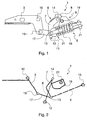
- the device In the position of figure 1 , the device is shown in a resting condition.
- the adjusting means 9 are designed so as to provide the minimum preload on the elastic means 6.
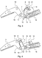
- the cam 19 is oriented so as its surface 20a, that is the surface closest to the constraint 21, abuts against the first crank 4 (see figure 5 ).
- the backrest frame 3 undergoes a rotation, counterclockwise in figures, and pushes the second connecting rod 17 towards the elastic means 5, that is to the right in figures.
- the first connecting rod 7 is dragged by the second connecting rod 17 by means of the constraint in the point of application 13, and rotates around the first crank 8 around the constraint 14.
- the first crank 8 substantially holds its position compared to the resting condition.
- the elastic means are compressed by means of the constraint 15, providing a resistance against the rotation of the backrest frame 3, until an equilibrium position, shown in figure 3 , is reached.
- the preload of the elastic means 5 varies.
- the cam 19 is rotated such that the first crank 8 rests on a surface 20b - 20f of the cam 19 different from the surface 20a.
- the rotation of the cam 19 is shown in figure 2 . Therefore the position shown in figure 2 is not an equilibrium position of the cam 19.
- the rotation of the cam 19 drags the first crank 8 and, particularly, causes a rotation of the first crank 8 around the constraint 12, for example counterclockwise in figures. Due to the constraint 14, also the first connecting rod 7 is moved. In the shown case, the first connecting rod 7 rotates clockwise and, due to the constraint 15, the elastic means 5 are slightly compressed.
- the crank 7 is not constrained to the base frame 2 of the chair, and thus it roto-translates in the space with respect to the base frame 2 of the chair, changing moment by moment its center of rotation, performing a series of acts of rotary motion that, in the shown case, are directed clockwise.
- the rotation of the backrest frame causes the first crank to rotate, and the latter, for example by means of a pusher, act on the elastic means to vary their preload, for example compressing a torsion spring similar to the spring 16 or else a flexure or gas spring.
- the operation of the cam 19 or of a similar adjusting means 9 can cause the crank 8 to rotate thereby driving the first connecting rod 7 to move, as in the embodiment shown.
- the first connecting rod 7 operates on the elastic means 5 to vary their preload by means of the mentioned pusher or the like, getting the same result as that described above with reference to the device shown in the figures.
Claims (7)
- Dispositif pour régler l'inclinaison d'un dossier de chaise, ledit dispositif comprenant un cadre de base (2) de la chaise, un cadre de dossier (3) monté au moins de manière rotative sur ledit cadre de base (2) de la chaise, et un moyen élastique (5) pour rappeler ledit dossier et/ou contrer la rotation de celui-ci, le moyen élastique (5) ayant au moins un point d'application (13) du rappel et/ou de la force de contre-rotation dudit dossier, ledit cadre de dossier (3) étant contraint par ledit moyen élastique (5) en correspondance avec ledit au moins un point d'application (13), ainsi que par un mécanisme de préchargement (7, 8) pour l'ajustement dudit moyen élastique (5), dans lequel ledit mécanisme de préchargement (7, 8) comprend au moins une première tige de connexion (7) s'articulant sur au moins une première bielle (8) et contrainte par ledit moyen élastique (5) dans le point d'application (13) pour déplacer ledit point d'application (13) en fonction de la position adoptée par ladite au moins une première tige de connexion (7) par rapport audit cadre de base (2), ladite au moins une première bielle (8) s'articulant sur ledit cadre de base (2) pour faire tourner le point d'articulation (14) de ladite au moins une première tige de connexion (7) par rapport audit cadre de base (2), caractérisé en ce que ledit dispositif comprend un moyen d'ajustement (19) pour ajuster la position de ladite au moins une première bielle (8) dans au moins deux positions stables distinctes correspondant à au moins deux positions distinctes dudit au moins un point d'application (13) par rapport audit cadre de base (2).
- Dispositif selon la revendication 1, dans lequel ledit moyen élastique (5) comprend un support mobile (21).
- Dispositif selon la revendication 1 ou 2, dans lequel ledit support mobile dudit moyen élastique (5) est contraint au moins en rotation par ledit cadre de base (2) de ladite chaise.
- Dispositif selon l'une des revendications précédentes, dans lequel une seconde tige de connexion (17) s'articule dans le point d'application (13) dudit moyen élastique (5) sur ladite au moins une première tige de connexion (7), et dans un second point (18) sur ledit cadre de dossier (3).
- Dispositif selon la revendication 2, dans lequel ladite au moins une première tige de connexion (7) s'articule sur ledit support (21) dudit moyen élastique (5) en correspondance avec ledit au moins un point d'application (13) ou à proximité de celui-ci.
- Dispositif selon l'une des revendications précédentes, dans lequel ledit moyen d'ajustement (9) comprend un dispositif à came actionnable manuellement (19) engagé avec ladite au moins une première bielle (8).
- Dispositif selon la revendication 6, dans lequel ledit dispositif à came (19) comprend au moins deux surfaces de contact (20a) en contact avec ladite au moins une première bielle (8), lesdites surfaces de contact étant sensiblement plates et inclinées l'une par rapport à l'autre.
Priority Applications (10)
| Application Number | Priority Date | Filing Date | Title |
|---|---|---|---|
| PL13197786T PL2886015T3 (pl) | 2013-12-17 | 2013-12-17 | Fotel z regulowanym oparciem |
| EP13197786.0A EP2886015B1 (fr) | 2013-12-17 | 2013-12-17 | Chaise avec dossier ajustable |
| CN201480068400.4A CN105848525B (zh) | 2013-12-17 | 2014-12-11 | 具有可调整靠背的椅子 |
| TW103143189A TWI641345B (zh) | 2013-12-17 | 2014-12-11 | 具有可調整式背墊之椅子 |
| CA2930916A CA2930916C (fr) | 2013-12-17 | 2014-12-11 | Siege a dossier reglable |
| TW103221965U TWM507225U (zh) | 2013-12-17 | 2014-12-11 | 具有可調整式背墊之椅子 |
| KR1020167014513A KR102307892B1 (ko) | 2013-12-17 | 2014-12-11 | 조절 가능한 등받이를 구비한 의자 |
| US15/104,398 US10098466B2 (en) | 2013-12-17 | 2014-12-11 | Chair with adjustable backrest |
| PCT/EP2014/077362 WO2015091199A1 (fr) | 2013-12-17 | 2014-12-11 | Siège à dossier réglable |
| HK15111416.6A HK1210681A1 (zh) | 2013-12-17 | 2015-11-19 | 具有可調節靠背的椅子 |
Applications Claiming Priority (1)
| Application Number | Priority Date | Filing Date | Title |
|---|---|---|---|
| EP13197786.0A EP2886015B1 (fr) | 2013-12-17 | 2013-12-17 | Chaise avec dossier ajustable |
Publications (2)
| Publication Number | Publication Date |
|---|---|
| EP2886015A1 EP2886015A1 (fr) | 2015-06-24 |
| EP2886015B1 true EP2886015B1 (fr) | 2016-07-13 |
Family
ID=50072814
Family Applications (1)
| Application Number | Title | Priority Date | Filing Date |
|---|---|---|---|
| EP13197786.0A Active EP2886015B1 (fr) | 2013-12-17 | 2013-12-17 | Chaise avec dossier ajustable |
Country Status (9)
| Country | Link |
|---|---|
| US (1) | US10098466B2 (fr) |
| EP (1) | EP2886015B1 (fr) |
| KR (1) | KR102307892B1 (fr) |
| CN (1) | CN105848525B (fr) |
| CA (1) | CA2930916C (fr) |
| HK (1) | HK1210681A1 (fr) |
| PL (1) | PL2886015T3 (fr) |
| TW (2) | TWM507225U (fr) |
| WO (1) | WO2015091199A1 (fr) |
Cited By (1)
| Publication number | Priority date | Publication date | Assignee | Title |
|---|---|---|---|---|
| US11350750B2 (en) | 2018-04-17 | 2022-06-07 | L&P Property Management Company | Tilt mechanism for a chair and chair |
Families Citing this family (11)
| Publication number | Priority date | Publication date | Assignee | Title |
|---|---|---|---|---|
| DE202013100574U1 (de) * | 2013-02-07 | 2014-05-08 | Bock 1 Gmbh & Co. Kg | Mechanik für einen Bürostuhl |
| DE202013102059U1 (de) * | 2013-05-11 | 2014-08-12 | Bock 1 Gmbh & Co. Kg | Synchronmechanik |
| MY189850A (en) | 2015-04-13 | 2022-03-14 | Steelcase Inc | Seating arrangement |
| US10194750B2 (en) | 2015-04-13 | 2019-02-05 | Steelcase Inc. | Seating arrangement |
| US11259637B2 (en) | 2015-04-13 | 2022-03-01 | Steelcase Inc. | Seating arrangement |
| CN108635167B (zh) * | 2018-05-30 | 2024-02-20 | 宁波秉航科技集团有限公司 | 一种按摩椅框架结构 |
| US11109683B2 (en) | 2019-02-21 | 2021-09-07 | Steelcase Inc. | Body support assembly and method for the use and assembly thereof |
| US11357329B2 (en) | 2019-12-13 | 2022-06-14 | Steelcase Inc. | Body support assembly and methods for the use and assembly thereof |
| WO2021178206A1 (fr) | 2020-03-02 | 2021-09-10 | Steelcase Inc. | Ensemble de support de corps et ses procédés d'utilisation et d'assemblage |
| WO2021237811A1 (fr) * | 2020-05-28 | 2021-12-02 | 安吉德卡办公系统有限公司 | Appareil de liaison de siège à dossier réglable |
| WO2022173799A1 (fr) | 2021-02-10 | 2022-08-18 | Steelcase Inc. | Structures de support corporel |
Family Cites Families (49)
| Publication number | Priority date | Publication date | Assignee | Title |
|---|---|---|---|---|
| GB724329A (en) | 1952-04-25 | 1955-02-16 | Albert Ducrot | Improvements in or relating to convertible chairs |
| AU430169B2 (en) | 1968-10-11 | 1972-11-15 | Hodge Investments Proprietary Limited' | Invalid chair |
| FR2045120A5 (fr) | 1969-06-03 | 1971-02-26 | Dupart Jean | |
| CN85104321A (zh) * | 1985-06-07 | 1986-12-03 | 株式会社伊藤喜工作所 | 椅子 |
| DE3521488A1 (de) | 1985-06-14 | 1986-12-18 | August Fröscher GmbH & Co KG, 7141 Steinheim | Arbeitsstuhl |
| DE3617623A1 (de) | 1986-05-26 | 1987-12-03 | Drabert Soehne | Stuhl |
| DE8713972U1 (fr) | 1987-10-17 | 1987-11-26 | Nikov, Ljubomir, 6457 Maintal, De | |
| US5026117A (en) * | 1987-11-10 | 1991-06-25 | Steelcase Inc. | Controller for seating and the like |
| EP0461228B1 (fr) | 1989-12-29 | 1994-08-31 | Wilkhahn Wilkening + Hahne GmbH + Co. | Dispositif de reglage synchrone pour chaises de bureau ou analogues |
| AU1692092A (en) | 1991-05-24 | 1992-12-30 | Equus Marketing Ag | Working chair, especially office chair |
| DE4118570A1 (de) | 1991-06-06 | 1992-12-10 | Simon Desanta | Stuhl, insbesondere buerostuhl |
| IL103477A0 (en) | 1992-10-20 | 1993-03-15 | Paltechnica Nitzanim | Office and like chairs |
| CA2116079C (fr) | 1993-02-22 | 2005-12-27 | Benjamin Cowan | Chaise |
| DE4306970C2 (de) | 1993-03-05 | 1995-05-04 | Drabert Soehne | Sitzmöbel, insbesondere Bürostuhl |
| AT402602B (de) | 1995-02-28 | 1997-07-25 | Eckhard Hansen Dipl Ing | Stuhl stuhl |
| ES2182017T3 (es) * | 1996-10-14 | 2003-03-01 | Vitra Patente Ag | Mecanismo para sillas. |
| AT405124B (de) * | 1997-04-14 | 1999-05-25 | Eckhard Hansen Dipl Ing | Stuhl |
| DE19849521A1 (de) * | 1998-10-21 | 2000-04-27 | Drabert Gmbh | Bürostuhl mit nachführbarer Rückenlehne |
| US6709058B1 (en) | 1999-04-09 | 2004-03-23 | Humanscale Corp. | Ergonomic chair |
| AR026126A1 (es) | 1999-06-04 | 2003-01-29 | Softview Comp Products Corp | Una silla reclinable |
| GB0100388D0 (en) * | 2001-01-06 | 2001-02-14 | Unit Press Ltd | Chairs |
| DE10122945A1 (de) | 2001-05-11 | 2002-12-12 | Armin Sander | Stuhl, insbesondere Bürostuhl |
| CN2488383Y (zh) * | 2001-07-04 | 2002-05-01 | 富锢有限公司 | 座椅靠背体倾斜角度的控制机构 |
| JP4848099B2 (ja) * | 2001-07-18 | 2011-12-28 | タカノ株式会社 | 椅子 |
| US20030132653A1 (en) * | 2001-10-18 | 2003-07-17 | Doug Thole | Tension control mechanism for a chair |
| DE10241562A1 (de) | 2002-09-07 | 2004-03-18 | Bock-1 Gmbh & Co. | Synchronmechanik für Bürostühle |
| DE10302208A1 (de) | 2003-01-22 | 2004-07-29 | Klöber GmbH | Stuhl mit schnell verstellbarem Kraftspeicher |
| US8615828B2 (en) | 2003-02-10 | 2013-12-31 | Ferdinand Schermel | Multi-position reclining bed |
| ITTO20030152A1 (it) * | 2003-03-04 | 2004-09-05 | Pro Cord Spa | Sedia con sedile oscillante. |
| US6848042B1 (en) | 2003-03-28 | 2005-01-25 | Xilinx, Inc. | Integrated circuit and method of outputting data from a FIFO |
| CN2629543Y (zh) * | 2003-05-16 | 2004-08-04 | 刘义丰 | 具有倾仰角度的座椅结构 |
| ITVE20050027A1 (it) | 2005-04-28 | 2006-10-29 | Imarc Spa | Dispositivo di regolazione della forza di oscillazione in meccanismi per sedie da ufficio. |
| DE202005011725U1 (de) | 2005-07-27 | 2006-12-07 | Sander, Armin | Stuhl, insbesondere Bürostuhl |
| GB0517384D0 (en) | 2005-08-26 | 2005-10-05 | Birkbeck Hilary R | Variable configuration seating |
| CN2930451Y (zh) * | 2005-11-29 | 2007-08-08 | 索志强 | 康体休闲沙发 |
| DE202007001395U1 (de) | 2007-01-31 | 2008-06-05 | Sander, Armin | Stuhl, insbesondere Bürostuhl |
| ITTO20070398A1 (it) | 2007-06-06 | 2008-12-07 | Malenotti S R L | "sedia con schienale oscillante" |
| CN201091373Y (zh) * | 2007-08-15 | 2008-07-30 | 多纳蒂合资公司 | 摇椅同步倾仰机构 |
| CN201085301Y (zh) * | 2007-10-08 | 2008-07-16 | 刘智清 | 办公椅的升降、倾仰调节装置 |
| ITVI20080057A1 (it) * | 2008-03-07 | 2009-09-08 | Moving S R L | Dispositivo di regolazione per sedia ad uso ufficio |
| EP2375938B2 (fr) | 2009-02-25 | 2020-01-08 | Donati S.p.A. | Dispositif pour synchroniser l'inclinaison d'un dossier de siège et d'un siège |
| WO2010103554A1 (fr) | 2009-03-10 | 2010-09-16 | Effe Tre S.R.L. | Dispositif de support d'une chaise avec dossier inclinable |
| US8714645B2 (en) * | 2010-01-28 | 2014-05-06 | Sava Cvek | Pivoting mechanism with gross and fine resistance adjustment |
| KR101533650B1 (ko) * | 2010-04-15 | 2015-07-03 | 주식회사 시디즈 | 의자의 등받이에 작용하는 복원력을 조정하기 위한 조정 메커니즘 및 상기 조정 메커니즘을 구비한 사무용 의자 |
| TW201311188A (zh) * | 2011-07-15 | 2013-03-16 | Itoki Corp | 搖椅及使用於其之彈簧單元 |
| CN103957749B (zh) * | 2011-08-03 | 2017-02-22 | 霍沃思公司 | 设置作用在座椅靠背上的恢复力的调节机构以及具有这类调节机构的办公座椅 |
| USD697726S1 (en) * | 2012-09-20 | 2014-01-21 | Steelcase Inc. | Chair |
| DE202013100574U1 (de) * | 2013-02-07 | 2014-05-08 | Bock 1 Gmbh & Co. Kg | Mechanik für einen Bürostuhl |
| DE102014226645B4 (de) * | 2014-12-19 | 2023-10-05 | Hangzhou Zhongtai Industrial Group Co., Ltd. | Verstellmechanik zur Einstellung einer auf eine Rückenlehne eines Stuhls einwirkenden Rückstellkraft und Bürostuhl mit einer solchen Verstellmechanik |
-
2013
- 2013-12-17 EP EP13197786.0A patent/EP2886015B1/fr active Active
- 2013-12-17 PL PL13197786T patent/PL2886015T3/pl unknown
-
2014
- 2014-12-11 WO PCT/EP2014/077362 patent/WO2015091199A1/fr active Application Filing
- 2014-12-11 CN CN201480068400.4A patent/CN105848525B/zh active Active
- 2014-12-11 KR KR1020167014513A patent/KR102307892B1/ko active IP Right Grant
- 2014-12-11 TW TW103221965U patent/TWM507225U/zh unknown
- 2014-12-11 US US15/104,398 patent/US10098466B2/en active Active
- 2014-12-11 TW TW103143189A patent/TWI641345B/zh active
- 2014-12-11 CA CA2930916A patent/CA2930916C/fr active Active
-
2015
- 2015-11-19 HK HK15111416.6A patent/HK1210681A1/zh unknown
Cited By (1)
| Publication number | Priority date | Publication date | Assignee | Title |
|---|---|---|---|---|
| US11350750B2 (en) | 2018-04-17 | 2022-06-07 | L&P Property Management Company | Tilt mechanism for a chair and chair |
Also Published As
| Publication number | Publication date |
|---|---|
| HK1210681A1 (zh) | 2016-05-06 |
| US20160309902A1 (en) | 2016-10-27 |
| CA2930916A1 (fr) | 2015-06-25 |
| KR102307892B1 (ko) | 2021-10-01 |
| WO2015091199A1 (fr) | 2015-06-25 |
| CA2930916C (fr) | 2022-01-18 |
| CN105848525A (zh) | 2016-08-10 |
| KR20160098214A (ko) | 2016-08-18 |
| EP2886015A1 (fr) | 2015-06-24 |
| TWM507225U (zh) | 2015-08-21 |
| PL2886015T3 (pl) | 2017-01-31 |
| TW201531268A (zh) | 2015-08-16 |
| US10098466B2 (en) | 2018-10-16 |
| CN105848525B (zh) | 2019-05-03 |
| TWI641345B (zh) | 2018-11-21 |
Similar Documents
| Publication | Publication Date | Title |
|---|---|---|
| EP2886015B1 (fr) | Chaise avec dossier ajustable | |
| CA2680686C (fr) | Dispositif de reglage pour chaise inclinable | |
| US9326609B2 (en) | Chair chassis and chair having the same | |
| EP1865810B1 (fr) | Mécanisme de synchronisation pour chaises et fauteuils | |
| EP3122210B1 (fr) | Dispositif de synchronisation d'inclinaison de dossier et de siège de chaise | |
| US9277821B2 (en) | Tilt mechanism for a chair and chair | |
| US20200268155A1 (en) | Oscillation system for chairs | |
| WO2010056838A1 (fr) | Dispositif pour ajuster la poussée d'un mécanisme, en particulier pour des chaises ajustables | |
| KR101952033B1 (ko) | 의자의 틸팅 레인지용 조절장치 | |
| CA2547457C (fr) | Chaise a hauteur reglable avec fonction bercante | |
| KR20170004293U (ko) | 의자 좌판 경사장치 | |
| CN106419239B (zh) | 座背联动椅阻尼机构的调节结构 | |
| KR101232984B1 (ko) | 의자 좌판 경사장치 | |
| KR20140068348A (ko) | 의자 좌판 경사장치 | |
| CN106165986B (zh) | 一种座背联动椅的阻尼调节机构及底座联动机构 | |
| KR102083157B1 (ko) | 의자의 틸트 교번 기구 | |
| KR101367001B1 (ko) | 의자 좌판 경사장치 | |
| KR102303651B1 (ko) | 의자용 좌판의 국부 변동 구조 | |
| EP4179925A1 (fr) | Siège, en particulier chaise médicale | |
| KR20190072707A (ko) | 의자의 기울임 강도 조절장치 | |
| EP1992254A1 (fr) | Dispositif de changement de réglage d'un siège | |
| JP2004248980A (ja) | 椅子 |
Legal Events
| Date | Code | Title | Description |
|---|---|---|---|
| PUAI | Public reference made under article 153(3) epc to a published international application that has entered the european phase |
Free format text: ORIGINAL CODE: 0009012 |
|
| 17P | Request for examination filed |
Effective date: 20131217 |
|
| AK | Designated contracting states |
Kind code of ref document: A1 Designated state(s): AL AT BE BG CH CY CZ DE DK EE ES FI FR GB GR HR HU IE IS IT LI LT LU LV MC MK MT NL NO PL PT RO RS SE SI SK SM TR |
|
| AX | Request for extension of the european patent |
Extension state: BA ME |
|
| R17P | Request for examination filed (corrected) |
Effective date: 20151119 |
|
| RBV | Designated contracting states (corrected) |
Designated state(s): AL AT BE BG CH CY CZ DE DK EE ES FI FR GB GR HR HU IE IS IT LI LT LU LV MC MK MT NL NO PL PT RO RS SE SI SK SM TR |
|
| GRAP | Despatch of communication of intention to grant a patent |
Free format text: ORIGINAL CODE: EPIDOSNIGR1 |
|
| INTG | Intention to grant announced |
Effective date: 20160321 |
|
| RIN1 | Information on inventor provided before grant (corrected) |
Inventor name: DONATI, ARMANDO |
|
| REG | Reference to a national code |
Ref country code: HK Ref legal event code: DE Ref document number: 1210681 Country of ref document: HK |
|
| GRAS | Grant fee paid |
Free format text: ORIGINAL CODE: EPIDOSNIGR3 |
|
| GRAA | (expected) grant |
Free format text: ORIGINAL CODE: 0009210 |
|
| AK | Designated contracting states |
Kind code of ref document: B1 Designated state(s): AL AT BE BG CH CY CZ DE DK EE ES FI FR GB GR HR HU IE IS IT LI LT LU LV MC MK MT NL NO PL PT RO RS SE SI SK SM TR |
|
| REG | Reference to a national code |
Ref country code: GB Ref legal event code: FG4D |
|
| REG | Reference to a national code |
Ref country code: AT Ref legal event code: REF Ref document number: 811569 Country of ref document: AT Kind code of ref document: T Effective date: 20160715 Ref country code: CH Ref legal event code: EP |
|
| REG | Reference to a national code |
Ref country code: IE Ref legal event code: FG4D |
|
| REG | Reference to a national code |
Ref country code: DE Ref legal event code: R096 Ref document number: 602013009310 Country of ref document: DE |
|
| REG | Reference to a national code |
Ref country code: LT Ref legal event code: MG4D |
|
| REG | Reference to a national code |
Ref country code: NL Ref legal event code: MP Effective date: 20160713 |
|
| REG | Reference to a national code |
Ref country code: FR Ref legal event code: PLFP Year of fee payment: 4 |
|
| REG | Reference to a national code |
Ref country code: AT Ref legal event code: MK05 Ref document number: 811569 Country of ref document: AT Kind code of ref document: T Effective date: 20160713 |
|
| PG25 | Lapsed in a contracting state [announced via postgrant information from national office to epo] |
Ref country code: FI Free format text: LAPSE BECAUSE OF FAILURE TO SUBMIT A TRANSLATION OF THE DESCRIPTION OR TO PAY THE FEE WITHIN THE PRESCRIBED TIME-LIMIT Effective date: 20160713 Ref country code: RS Free format text: LAPSE BECAUSE OF FAILURE TO SUBMIT A TRANSLATION OF THE DESCRIPTION OR TO PAY THE FEE WITHIN THE PRESCRIBED TIME-LIMIT Effective date: 20160713 Ref country code: LT Free format text: LAPSE BECAUSE OF FAILURE TO SUBMIT A TRANSLATION OF THE DESCRIPTION OR TO PAY THE FEE WITHIN THE PRESCRIBED TIME-LIMIT Effective date: 20160713 Ref country code: NO Free format text: LAPSE BECAUSE OF FAILURE TO SUBMIT A TRANSLATION OF THE DESCRIPTION OR TO PAY THE FEE WITHIN THE PRESCRIBED TIME-LIMIT Effective date: 20161013 Ref country code: NL Free format text: LAPSE BECAUSE OF FAILURE TO SUBMIT A TRANSLATION OF THE DESCRIPTION OR TO PAY THE FEE WITHIN THE PRESCRIBED TIME-LIMIT Effective date: 20160713 Ref country code: IS Free format text: LAPSE BECAUSE OF FAILURE TO SUBMIT A TRANSLATION OF THE DESCRIPTION OR TO PAY THE FEE WITHIN THE PRESCRIBED TIME-LIMIT Effective date: 20161113 Ref country code: HR Free format text: LAPSE BECAUSE OF FAILURE TO SUBMIT A TRANSLATION OF THE DESCRIPTION OR TO PAY THE FEE WITHIN THE PRESCRIBED TIME-LIMIT Effective date: 20160713 |
|
| PG25 | Lapsed in a contracting state [announced via postgrant information from national office to epo] |
Ref country code: AT Free format text: LAPSE BECAUSE OF FAILURE TO SUBMIT A TRANSLATION OF THE DESCRIPTION OR TO PAY THE FEE WITHIN THE PRESCRIBED TIME-LIMIT Effective date: 20160713 Ref country code: BE Free format text: LAPSE BECAUSE OF FAILURE TO SUBMIT A TRANSLATION OF THE DESCRIPTION OR TO PAY THE FEE WITHIN THE PRESCRIBED TIME-LIMIT Effective date: 20160713 Ref country code: ES Free format text: LAPSE BECAUSE OF FAILURE TO SUBMIT A TRANSLATION OF THE DESCRIPTION OR TO PAY THE FEE WITHIN THE PRESCRIBED TIME-LIMIT Effective date: 20160713 Ref country code: GR Free format text: LAPSE BECAUSE OF FAILURE TO SUBMIT A TRANSLATION OF THE DESCRIPTION OR TO PAY THE FEE WITHIN THE PRESCRIBED TIME-LIMIT Effective date: 20161014 Ref country code: PT Free format text: LAPSE BECAUSE OF FAILURE TO SUBMIT A TRANSLATION OF THE DESCRIPTION OR TO PAY THE FEE WITHIN THE PRESCRIBED TIME-LIMIT Effective date: 20161114 Ref country code: LV Free format text: LAPSE BECAUSE OF FAILURE TO SUBMIT A TRANSLATION OF THE DESCRIPTION OR TO PAY THE FEE WITHIN THE PRESCRIBED TIME-LIMIT Effective date: 20160713 Ref country code: SE Free format text: LAPSE BECAUSE OF FAILURE TO SUBMIT A TRANSLATION OF THE DESCRIPTION OR TO PAY THE FEE WITHIN THE PRESCRIBED TIME-LIMIT Effective date: 20160713 |
|
| REG | Reference to a national code |
Ref country code: DE Ref legal event code: R097 Ref document number: 602013009310 Country of ref document: DE |
|
| PG25 | Lapsed in a contracting state [announced via postgrant information from national office to epo] |
Ref country code: EE Free format text: LAPSE BECAUSE OF FAILURE TO SUBMIT A TRANSLATION OF THE DESCRIPTION OR TO PAY THE FEE WITHIN THE PRESCRIBED TIME-LIMIT Effective date: 20160713 Ref country code: RO Free format text: LAPSE BECAUSE OF FAILURE TO SUBMIT A TRANSLATION OF THE DESCRIPTION OR TO PAY THE FEE WITHIN THE PRESCRIBED TIME-LIMIT Effective date: 20160713 |
|
| PLBE | No opposition filed within time limit |
Free format text: ORIGINAL CODE: 0009261 |
|
| STAA | Information on the status of an ep patent application or granted ep patent |
Free format text: STATUS: NO OPPOSITION FILED WITHIN TIME LIMIT |
|
| REG | Reference to a national code |
Ref country code: HK Ref legal event code: GR Ref document number: 1210681 Country of ref document: HK |
|
| PG25 | Lapsed in a contracting state [announced via postgrant information from national office to epo] |
Ref country code: SK Free format text: LAPSE BECAUSE OF FAILURE TO SUBMIT A TRANSLATION OF THE DESCRIPTION OR TO PAY THE FEE WITHIN THE PRESCRIBED TIME-LIMIT Effective date: 20160713 Ref country code: BG Free format text: LAPSE BECAUSE OF FAILURE TO SUBMIT A TRANSLATION OF THE DESCRIPTION OR TO PAY THE FEE WITHIN THE PRESCRIBED TIME-LIMIT Effective date: 20161013 Ref country code: DK Free format text: LAPSE BECAUSE OF FAILURE TO SUBMIT A TRANSLATION OF THE DESCRIPTION OR TO PAY THE FEE WITHIN THE PRESCRIBED TIME-LIMIT Effective date: 20160713 Ref country code: SM Free format text: LAPSE BECAUSE OF FAILURE TO SUBMIT A TRANSLATION OF THE DESCRIPTION OR TO PAY THE FEE WITHIN THE PRESCRIBED TIME-LIMIT Effective date: 20160713 Ref country code: CZ Free format text: LAPSE BECAUSE OF FAILURE TO SUBMIT A TRANSLATION OF THE DESCRIPTION OR TO PAY THE FEE WITHIN THE PRESCRIBED TIME-LIMIT Effective date: 20160713 |
|
| 26N | No opposition filed |
Effective date: 20170418 |
|
| REG | Reference to a national code |
Ref country code: CH Ref legal event code: PL |
|
| PG25 | Lapsed in a contracting state [announced via postgrant information from national office to epo] |
Ref country code: SI Free format text: LAPSE BECAUSE OF FAILURE TO SUBMIT A TRANSLATION OF THE DESCRIPTION OR TO PAY THE FEE WITHIN THE PRESCRIBED TIME-LIMIT Effective date: 20160713 |
|
| PG25 | Lapsed in a contracting state [announced via postgrant information from national office to epo] |
Ref country code: MC Free format text: LAPSE BECAUSE OF FAILURE TO SUBMIT A TRANSLATION OF THE DESCRIPTION OR TO PAY THE FEE WITHIN THE PRESCRIBED TIME-LIMIT Effective date: 20160713 |
|
| REG | Reference to a national code |
Ref country code: IE Ref legal event code: MM4A |
|
| PG25 | Lapsed in a contracting state [announced via postgrant information from national office to epo] |
Ref country code: LU Free format text: LAPSE BECAUSE OF NON-PAYMENT OF DUE FEES Effective date: 20161217 Ref country code: LI Free format text: LAPSE BECAUSE OF NON-PAYMENT OF DUE FEES Effective date: 20161231 Ref country code: CH Free format text: LAPSE BECAUSE OF NON-PAYMENT OF DUE FEES Effective date: 20161231 |
|
| PG25 | Lapsed in a contracting state [announced via postgrant information from national office to epo] |
Ref country code: IE Free format text: LAPSE BECAUSE OF NON-PAYMENT OF DUE FEES Effective date: 20161217 |
|
| REG | Reference to a national code |
Ref country code: FR Ref legal event code: PLFP Year of fee payment: 5 |
|
| PG25 | Lapsed in a contracting state [announced via postgrant information from national office to epo] |
Ref country code: HU Free format text: LAPSE BECAUSE OF FAILURE TO SUBMIT A TRANSLATION OF THE DESCRIPTION OR TO PAY THE FEE WITHIN THE PRESCRIBED TIME-LIMIT; INVALID AB INITIO Effective date: 20131217 |
|
| PG25 | Lapsed in a contracting state [announced via postgrant information from national office to epo] |
Ref country code: CY Free format text: LAPSE BECAUSE OF FAILURE TO SUBMIT A TRANSLATION OF THE DESCRIPTION OR TO PAY THE FEE WITHIN THE PRESCRIBED TIME-LIMIT Effective date: 20160713 Ref country code: MK Free format text: LAPSE BECAUSE OF FAILURE TO SUBMIT A TRANSLATION OF THE DESCRIPTION OR TO PAY THE FEE WITHIN THE PRESCRIBED TIME-LIMIT Effective date: 20160713 |
|
| PG25 | Lapsed in a contracting state [announced via postgrant information from national office to epo] |
Ref country code: MT Free format text: LAPSE BECAUSE OF NON-PAYMENT OF DUE FEES Effective date: 20161217 |
|
| PG25 | Lapsed in a contracting state [announced via postgrant information from national office to epo] |
Ref country code: AL Free format text: LAPSE BECAUSE OF FAILURE TO SUBMIT A TRANSLATION OF THE DESCRIPTION OR TO PAY THE FEE WITHIN THE PRESCRIBED TIME-LIMIT Effective date: 20160713 |
|
| PGFP | Annual fee paid to national office [announced via postgrant information from national office to epo] |
Ref country code: PL Payment date: 20221110 Year of fee payment: 10 |
|
| P01 | Opt-out of the competence of the unified patent court (upc) registered |
Effective date: 20230627 |
|
| PGFP | Annual fee paid to national office [announced via postgrant information from national office to epo] |
Ref country code: GB Payment date: 20231206 Year of fee payment: 11 |
|
| PGFP | Annual fee paid to national office [announced via postgrant information from national office to epo] |
Ref country code: TR Payment date: 20231022 Year of fee payment: 11 Ref country code: IT Payment date: 20231204 Year of fee payment: 11 Ref country code: FR Payment date: 20231120 Year of fee payment: 11 Ref country code: DE Payment date: 20231212 Year of fee payment: 11 |
|
| PGFP | Annual fee paid to national office [announced via postgrant information from national office to epo] |
Ref country code: PL Payment date: 20231019 Year of fee payment: 11 |