EP2881337A1 - Tête de distributeur d'aérosol - Google Patents
Tête de distributeur d'aérosol Download PDFInfo
- Publication number
- EP2881337A1 EP2881337A1 EP13196202.9A EP13196202A EP2881337A1 EP 2881337 A1 EP2881337 A1 EP 2881337A1 EP 13196202 A EP13196202 A EP 13196202A EP 2881337 A1 EP2881337 A1 EP 2881337A1
- Authority
- EP
- European Patent Office
- Prior art keywords
- chassis
- spray
- platform
- aerosol
- cap
- Prior art date
- Legal status (The legal status is an assumption and is not a legal conclusion. Google has not performed a legal analysis and makes no representation as to the accuracy of the status listed.)
- Granted
Links
- 239000004479 aerosol dispenser Substances 0.000 title claims description 25
- 239000007921 spray Substances 0.000 claims abstract description 70
- 239000000443 aerosol Substances 0.000 claims abstract description 38
- 238000000034 method Methods 0.000 claims abstract description 17
- 238000004519 manufacturing process Methods 0.000 claims description 8
- 230000000630 rising effect Effects 0.000 claims description 7
- 238000000465 moulding Methods 0.000 claims description 6
- 230000001419 dependent effect Effects 0.000 claims description 2
- 230000000903 blocking effect Effects 0.000 description 11
- 239000011324 bead Substances 0.000 description 5
- 230000008901 benefit Effects 0.000 description 3
- 230000014759 maintenance of location Effects 0.000 description 3
- 230000003993 interaction Effects 0.000 description 2
- 239000000463 material Substances 0.000 description 2
- 230000000452 restraining effect Effects 0.000 description 2
- 238000005507 spraying Methods 0.000 description 2
- 238000005728 strengthening Methods 0.000 description 2
- 239000004743 Polypropylene Substances 0.000 description 1
- DHKHKXVYLBGOIT-UHFFFAOYSA-N acetaldehyde Diethyl Acetal Natural products CCOC(C)OCC DHKHKXVYLBGOIT-UHFFFAOYSA-N 0.000 description 1
- 125000002777 acetyl group Chemical class [H]C([H])([H])C(*)=O 0.000 description 1
- 230000000712 assembly Effects 0.000 description 1
- 238000000429 assembly Methods 0.000 description 1
- 238000005452 bending Methods 0.000 description 1
- 239000002537 cosmetic Substances 0.000 description 1
- 230000000994 depressogenic effect Effects 0.000 description 1
- 230000000873 masking effect Effects 0.000 description 1
- 239000000203 mixture Substances 0.000 description 1
- 230000004048 modification Effects 0.000 description 1
- 238000012986 modification Methods 0.000 description 1
- 239000004033 plastic Substances 0.000 description 1
- -1 polypropylene Polymers 0.000 description 1
- 229920001155 polypropylene Polymers 0.000 description 1
- 230000008569 process Effects 0.000 description 1
- 239000011800 void material Substances 0.000 description 1
Images


Classifications
-
- B—PERFORMING OPERATIONS; TRANSPORTING
- B65—CONVEYING; PACKING; STORING; HANDLING THIN OR FILAMENTARY MATERIAL
- B65D—CONTAINERS FOR STORAGE OR TRANSPORT OF ARTICLES OR MATERIALS, e.g. BAGS, BARRELS, BOTTLES, BOXES, CANS, CARTONS, CRATES, DRUMS, JARS, TANKS, HOPPERS, FORWARDING CONTAINERS; ACCESSORIES, CLOSURES, OR FITTINGS THEREFOR; PACKAGING ELEMENTS; PACKAGES
- B65D83/00—Containers or packages with special means for dispensing contents
- B65D83/14—Containers or packages with special means for dispensing contents for delivery of liquid or semi-liquid contents by internal gaseous pressure, i.e. aerosol containers comprising propellant for a product delivered by a propellant
- B65D83/16—Containers or packages with special means for dispensing contents for delivery of liquid or semi-liquid contents by internal gaseous pressure, i.e. aerosol containers comprising propellant for a product delivered by a propellant characterised by the actuating means
- B65D83/20—Containers or packages with special means for dispensing contents for delivery of liquid or semi-liquid contents by internal gaseous pressure, i.e. aerosol containers comprising propellant for a product delivered by a propellant characterised by the actuating means operated by manual action, e.g. button-type actuator or actuator caps
- B65D83/205—Actuator caps, or peripheral actuator skirts, attachable to the aerosol container
-
- B—PERFORMING OPERATIONS; TRANSPORTING
- B65—CONVEYING; PACKING; STORING; HANDLING THIN OR FILAMENTARY MATERIAL
- B65D—CONTAINERS FOR STORAGE OR TRANSPORT OF ARTICLES OR MATERIALS, e.g. BAGS, BARRELS, BOTTLES, BOXES, CANS, CARTONS, CRATES, DRUMS, JARS, TANKS, HOPPERS, FORWARDING CONTAINERS; ACCESSORIES, CLOSURES, OR FITTINGS THEREFOR; PACKAGING ELEMENTS; PACKAGES
- B65D83/00—Containers or packages with special means for dispensing contents
- B65D83/14—Containers or packages with special means for dispensing contents for delivery of liquid or semi-liquid contents by internal gaseous pressure, i.e. aerosol containers comprising propellant for a product delivered by a propellant
- B65D83/28—Nozzles, nozzle fittings or accessories specially adapted therefor
- B65D83/30—Nozzles, nozzle fittings or accessories specially adapted therefor for guiding the flow of spray, e.g. funnels, hoods
- B65D83/303—Nozzles, nozzle fittings or accessories specially adapted therefor for guiding the flow of spray, e.g. funnels, hoods using extension tubes located in or at the outlet duct of the nozzle assembly
Definitions
- the present invention is in the field of dispenser head assemblies for use with conventional aerosol cans. More particularly, it relates to spray-through caps methods for their manufacture.
- Aerosol cans have traditionally been used with an actuator comprising a button, pressure upon which causing release of the contents of the aerosol can via a valve present in the centre of a valve cup at the top of the can.
- Such actuators are typically used with a removable cap, giving the benefit of preventing accidental discharge via inadvertent pressure upon the actuator button.
- Other actuators for aerosol cans comprise a so-called 'spray-through cap', i.e., one that can be left in place during spraying, the spray exiting the cap through an orifice therein.
- Actuators comprising a spray-through cap often comprise some form of locking means to prevent accidental discharge via inadvertent pressure upon the actuator button.
- the present invention is concerned with actuators comprising a spray-through cap and a flexible spray channel held between the valve stem of an associated aerosol can and a holding feature present within the spray-through cap.
- WO 11/003752 discloses an actuator comprising a spray-through cap having an actuator button located on its side. Inside there is a chassis with depressible platform and a centrally located spray channel linking the valve stem of an associated aerosol can to spray orifice.
- US 7984827 B2 (Precision Valve, 2011) discloses a lockable aerosol valve actuator with a rotatable top portion.
- the opening in the over-cap only aligns with the nozzle outlet when the dispenser is in its unlocked position.
- WO 10/092775 and WO 10/041411 disclose a pump dispenser with a flexible spray channel.
- an aerosol dispenser head comprising a chassis and a spray-through cap, the chassis comprising:
- a method of spraying a cosmetic composition onto the surface of the human body comprising the use of an aerosol dispenser head according to the first aspect of the invention.
- moulding tools suitable for use in the manufacture of an aerosol dispenser head according to the first aspect of the invention.
- the mould for the means for holding the flexible spray channel at a pre-selected angle of bend is independently interchangeable with an alternative mould or moulds, resulting in an alternative angle(s) of bend for the flexible spray channel.
- the present invention provides for an aerosol dispenser head that is easy to assemble and to use. Further, the invention incorporates an ease and flexibility of manufacture, enabling multiple actuators to be assembled with minimal process modification. This benefit comes in part from the flexible spray channel, which can be bent to wherever it is desired to exit a particular spray-through cap with which it is used.
- the spray channel is not moulded together with the component that attaches it to the associated aerosol can, herein the chassis. This is possible with dispenser heads according to the present invention and this significantly simplifies manufacture. This is possible because the spray channel is moulded as a straight, vertical feature and is only later bent into its desired final position.
- Flexibility in manufacture is enhanced by having a means for holding the flexible spray channel at a pre-selected angle of bend.
- a chassis comprising the features as detailed in the first aspect of the invention may be attached to a variety of spray-through caps comprising the features as detailed in the first aspect of the invention to generate a variety of aerosol dispensers.
- the chassis comprises means for holding the flexible spray channel at a pre-selected angle of bend.
- the spray-through cap it is typical for the spray-through cap not to comprise means for holding the flexible spray channel at a pre-selected angle of bend.
- the spray-through cap it is typical for the spray-through cap to comprise means for attachment to the chassis.
- the means for holding the spray channel at a pre-selected angle of bend is part of the chassis, it is non-central with respect to the horizontal cross-section of the chassis and typically interacts with a portion of the spray channel towards its terminal end.
- it comprises a hook or eye that interacts with a corresponding hook or eye that is a portion of the spray channel.
- the dispenser head comprises a locking means, preventing accidental discharge via inadvertent pressure upon the actuator button.
- the dispenser head comprises a locking collar that interacts with the chassis platform to allow or prevent depression thereof dependent upon its rotational positioning relative thereto.
- the locking collar may prevent depression of the chassis platform via interaction of a protrusion from the collar with a feature on the platform in a first relative rotational positioning, rotation of this protrusion to a second relative rotational positioning allowing depression of the platform.
- the annular ring of the chassis comprises an upstanding annular wall, a portion of which projects through a partial annular gap in the locking collar as described in paragraph immediately above.
- the upstanding annular wall comprises a retaining feature that aids retention of the spray-through cap when this is added.
- a lip or bead that interacts with a corresponding feature on the spray-through cap is suitable for this purpose.
- the platform of the chassis is centrally located within the annular ring thereof. This aids the balance of forces and pressures exerted upon the platform and passed to the valve stem of the associated aerosol can.
- orientation terms such as “horizontal/vertical”, “upper/lower” and “upward/downward” should be understood to refer to the aerosol dispenser head oriented in an upright manner as it would be on top of an upright aerosol can with which it is designed for use.
- the "front” of the aerosol dispenser head refers to the face or portion bearing the spray outlet and “rear” refers to the face or portion away from the spray outlet.
- the pressure upon the actuator button which causes downward pressure on the chassis platform may be in any direction, but is typically downward.
- moulding tools includes moulds for components.
- the "pre-determined angle of bend" for the flexible spray channel may be from 180° (i.e. straight) to 90° (i.e. bent from vertical at the bottom to horizontal at the terminal end).
- the pre-determined angle of bend is preferably less 180°, more preferably less than 165° and most preferably less than 150°. For each of these preferences, the pre-determined angle of bend is also preferred to be greater than 90°C.
- the actuator button used in accordance with the present invention preferably comprises a keel protruding downwards from its inner surface. This keel functions to transfer pressure on the actuator button into downward pressure upon the platform of the chassis.
- two such keels may be employed, orientated to equalise the pressure applied on either side of the valve stem of an associated aerosol can. The two keels may be located at an equal distance on either side of the valve stem, along a straight line passing through the valve stem, in order to achieve such pressure equalisation.
- the pressure exerted by a keel as described in the above paragraph may be transferred to the chassis platform with the aid of a wall, preferably two walls, projecting upwards from the chassis platform.
- a wall preferably two walls, projecting upwards from the chassis platform.
- Such wall or walls can aid in the equalisation of the pressure brought to bear on platform.
- the struts attaching the platform of the chassis to the annular ring of the chassis are preferably flexible, in order to ease axial movement of the platform relative to the annular ring.
- the flexibility in the struts may come from material selection and/or their mechanical design.
- the struts are hinged to aid their flexibility.
- the struts preferably number from 2 to 8, more preferably from 2 to 4 and most preferably 3.
- the components of the actuator cap are typically made from plastic.
- the spray-through cap and chassis may be made from polypropylene, as may the spray channel.
- the swirl chamber, if employed, is typically made using a spray insert preferably made from acetal.
- the method of assembly described above as the "third aspect of the invention” involves the spray-through cap being attached to the chassis before the assembly thereby generated is attached to the aerosol can.
- the means for attachment of the assembly to the aerosol can comprises attachment means on the chassis; this typically attaching to a valve cup of the aerosol can.
- the flexible spray channel is moulded in a straight vertical orientation and is subsequently bent to a pre-determined angle of less than 180° and secured at such angle by the retaining feature of the chassis.
- This method allows for easy moulding of the chassis and flexibility in the final chassis design, allow post-moulding bending of the spray channel to accommodate the particular spray-through cap chosen.
- a preferred and advantageous feature of above preliminary step of the method of assembly is that the flexible spray channel is moulded in one piece together with the other components of the chassis.
- the method of assembly preferably includes the combination of the components described in the above paragraph with a locking collar.
- a portion of the annular ring of the chassis is preferably pushed upwards through a partial annular gap in the locking collar before the chassis is attached to the aerosol can.
- a portion of the annular ring of the chassis is pushed upwards through the partial annular gap in the locking collar before the spray-through cap is attached to the chassis.
- the chassis (1) comprises an annular ring (2) designed for attachment to the valve cup of an associated aerosol can (not shown).
- the annular ring (2) is comprised of annular wall (2A) and an annular platform (2B) that protrudes horizontally inwards from the annular wall (2A). Protruding from the internal surface of the annular wall (2A) above the annular platform (2B), there are multiple vertical strengthening pillars (2C) that add to the resilience of the chassis (1).
- a lip (2D) Protruding from the external surface of the annular wall (2A) at its top, there is a lip (2D), designed to interact with the spray-through cap (18) and aid its retention (vide infra).
- the flexible struts (3) Centrally located within the annular ring (2) and linked to the annular platform (2B) by three flexible struts (3) is an oblong platform (4) capable of axially movement relative to the annular ring (2).
- the flexible struts (3) are centrally hinged to aid their flexibility.
- Two of the flexible struts (3) attach to opposite ends of the oblong platform (4) along its long axis; the third is at right angles to these.
- the former two flexible struts (3) are perforated to leave a cross design (3A) on their upper parts to reduce material usage and enhance resilience.
- the latter flexible strut (3) is imperforated.
- a bevelled hump (5) rises from the top surface of the oblong platform (4) along its long axis at its centre.
- the sections of the annular ring (2) adjacent to the opposite ends of the oblong platform (4) along its long axis have cut-away sections (2E) in the part of the annular wall (2A) extending above the annular platform (2B). These serve to accommodate features of the locking collar (13) (vide infra).
- a flexible spray channel (6) Rising vertically from the centre of the oblong platform (4) there is a flexible spray channel (6). It is shown in vertical orientation in Figure 1 ; however, it is bent and locked into place during the assembly of the aerosol dispenser head (vide infra). At its lower end, the spray channel (6) is attachable to the valve stem of an associated aerosol can. At its outer end there is an exit orifice (7), allowing egress of the contents of the associated aerosol container when the valve of the latter is opened.
- a cylindrical outer shell (7C) Surrounding the outer part of the spray channel (6), close to the exit orifice (7), there is a cylindrical outer shell (7C) attached to the spray channel (6) at its lower end. There is a gap (7B) between the spray channel (6) and the cylindrical outer shell (7C) which can serve to accommodate a swirl chamber (not illustrated), if so desired.
- a masking plate (7A) Surrounding the exit orifice (7) and the associated cylindrical outer shell (7C) there is a masking plate (7A) which serves to mask a hole (20) in the associated spray through cap (18) (vide infra).
- a hook feature (8) extends radially outwards in a direction away from that in which the imperforated flexible strut (3) radially extends.
- the spray channel retaining feature (9) extends radially away in a direction parallel to the hook feature and projects upwards in arcuate cross-section.
- the spray channel retaining feature (9) has an indent (10) in its lower side designed to capture the hook feature (8) of the flexible spray channel (6) when the latter is bent over towards it and snapped into place.
- Figure 2 additionally illustrates the bore (6A) of the flexible spray channel (6) and its valve socket (6B), which sits on top of the valve stem of an associated aerosol can. Also illustrated is a bead (11) which snap connects the chassis (1) to the valve cup of the associated aerosol can with which it designed to be used. Also illustrated is a restraining hook (12) used in assembly to hold the oblong platform (4) and associated features in their pre-actuation position. The restraining hook (12) locks under the annular platform (2B) to achieve this.
- FIG 3 illustrates the chassis (1) with the flexible valve stem (6) bent over and the hook feature (8) thereof held by the retaining feature (9) also rising from the top surface of the oblong platform (4).
- the imperforated flexible strut (3) is bent to almost 90°, the oblong platform (4) being in its pre-actuation position.
- FIG 4 illustrates a locking collar (13) suitable for use with the chassis (1).
- the locking collar (13) comprises an outer collar (13A) and an inner collar (13B) concentric therewith, the two collars being held firmly together by two radially opposed horizontal linking struts (14).
- the inner collar (13B) is higher than the outer collar (13A) and the linking struts (14) link segments of the lower outer edge of the former with segments of the upper inner edge of the latter.
- the gap (15) between the outer collar (13A) and the inner collar (13B) is designed to accommodate the annular wall (2A) of the annular ring (2) when the dispenser head is assembled.
- the linking struts (14) sit on the annular platform (2B) in the cut-away sections (2E) in the part of the annular wall (2A) extending above the annular platform (2B) (see Figure 5 ).
- blocking elements (16) Projecting inwards from the inner side of the inner collar (13B) are blocking elements (16).
- the blocking elements are radially located to either side of where each of the linking struts (14) contacts the lower outer edge of the inner collar (13B).
- the blocking elements (16) serve to block depression of the oblong platform (4) and associated spray channel (6) when the locking collar (13) is appropriately rotated (vide infra).
- the blocked position of the locking collar (13) is clearly illustrated in Figure 5 .
- Four blocking elements (16) interact with four downward projections (17) from the oblong platform (4) and thereby prevent depression of the latter.
- the locking collar (13) is rotated such that the blocking elements (16) are clear of the downward projections (17) from the oblong platform (4), the oblong platform (4) may be depressed by downward pressure thereupon.
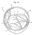
- FIGs 6 and 7 illustrate a spray-through cap (18) suitable for use in combination with the chassis (1) and locking collar (3) as described hereinabove.
- the spray-through cap (18) comprises an annular shell (19) defining an aperture (20) designed to accommodate the exit orifice (7) of the spray channel (6).
- the shell (19) is largely cylindrical in shape, but has a lip (21) slightly overlapping a central void (22) at its upper end.
- an actuator button (23) Attached to the of the shell (19) at its upper edge facing away from the aperture (20) there is an actuator button (23).
- the actuator button (23) fills most of the top surface of the spray through cap (18) bordered by the lip (21) protruding inwards from the shell (19) thereof.
- the actuator button (23) is linked to the shell (19) at its upper edge by a living hinge (24) located opposite the aperture (20) defined in the shell (19) of the spray-through cap (18).
- the shell (19) has several strengthening struts (25) located on its inner surface and running vertically for all or part of the total height of the shell (19). Protruding from the inner surface of the shell (19) towards it lower end there is an annular bead (26) designed to interact with the lip (2D) on the chassis (1) and aid the retention of the spray-through cap (18) on the chassis (1).
- the underside of the actuator button (23) comprises two downward protruding keels (27) having an arch-shaped support (28) therebetween.
- the high point of the arch-shaped support (28) accommodates the flexed spray channel (6) when the dispenser head is fully assembled.
- an actuator button (123) comprises two downward protruding keels (127) having a cross-beam support (128) therebetween.
- the keels (27) press on the bevelled hump (5) on the top surface of the oblong platform (4) at points equidistant from the centrally located spray channel (6).
- the locking collar (13) is in a position to allow depression of the oblong platform (4), the downward pressure on the bevelled hump (5) thereof causes the valve socket (6B) to press down upon the valve stem an associated aerosol container and thereby allow release of the contents of the later through the spray channel (6).
- an alternative chassis (101) comprises an annular ring (102) designed for attachment to the valve cup of an associated aerosol can (not shown).
- the annular ring (102) is comprised of numerous features as previously described for the annular ring bearing reference numeral (2); the description of most of these features will not be repeated with reference to this embodiment.
- the projection (1 02F) from outer surface of the annular wall (102A) of the chassis is discussed further herein (vide infra).
- oblong platform (104) Centrally located within the annular ring (102) and linked to the annular platform (102B) by three flexible struts (103) (two illustrated) is an oblong platform (104) capable of axial movement relative to the annular ring (102).
- the flexible struts (103) are centrally hinged to aid their flexibility.
- Two of the flexible struts (103) attach to opposite ends of the oblong platform (104) along its long axis; the third is at right angles to these.
- the oblong platform (104) bears inwardly bevelled walls (105) close to each of its long sides, the walls (105) protruding upwards a distance approximately 20% of the breadth of the oblong platform (104).
- the bevelled walls (105) serve to aid delivery of pressure from the keels (127) protruding from the underside of the actuator button (123) ( vide supra ) onto the oblong platform (104) of the chassis (101) when the dispenser is actuated.
- FIG 11 illustrates an alternative locking collar (113) suitable for use with the chassis (101).
- the locking collar (113) comprises numerous features as previously described for the locking collar bearing reference numeral (13); the description of most of these features will not be repeated with reference to this embodiment.
- blocking elements (116) projecting inwards from the inner side of an inner collar (113B). These blocking elements each have anti-rotation protrusions (116A) protruding from their upper surfaces towards their counter-clockwise edge.
- the blocking elements (116) interact with four downward projections (117) from the oblong platform (114) and thereby prevent depression of the latter (see Figure 12 ) when the locking collar (113) is rotated to its most clockwise position.
- Figure 13 illustrates the situation when the locking collar (113) is rotated counter-clockwise to a position where the downward projections (117) from the oblong platform (114) may pass the blocking elements (116) of the locking collar (113). In this position, downward pressure upon the platform (106) causes the opening of the valve located under the flexible spray channel (106) and release of the contents of the associated aerosol can.
- FIG 15 illustrates the combination of the chassis (101) illustrated in Figure 9 ; the locking collar (113) as illustrated in Figure 11 ; and the spray-through cap (118) illustrated in Figure 14 .
- the spray-through cap (118) sits over the chassis (101) and almost abuts the top edge of the locking collar (113) with its lower edge.
- the spray-through cap (118) is attached to the chassis (101) by means of an incomplete annular bead (126) in the former fitting under an annular lip (102D) in the latter.
- the incomplete annular bead (126) may also be seen in Figure 14 .
- the locking collar (113) has an annular lip (113C) projecting inwards from the upper end of an outer collar (113A) thereof. This inward projecting lip (113C) sits on top of narrow projections (1 02F) from the outer surface of the annular wall (102A) of the chassis (101), of which there are two (one illustrated in Figure 9 ).
- the projections (1 02F) are located diagonally opposite one another at either end of a diagonal orthogonal to the long axis of the oblong platform (104).
- the projections (1 02F) terminate at an upper height equal to that of the annular platform (102B).
- a keel (127) projecting from the underside of the actuator button (123) contacts the rear bevelled wall (105) projecting from the oblong platform (104). Whilst obscured by the spray channel retaining feature (109) in Figure 15 , the keel (127) referred to immediately above also contacts the front bevelled wall (105) projecting from the oblong platform (104), thereby equalising pressure thereupon when the dispenser is actuated. This is true for both keels (127) as depicted in Figure 14 .
Landscapes
- Chemical & Material Sciences (AREA)
- Dispersion Chemistry (AREA)
- Engineering & Computer Science (AREA)
- Mechanical Engineering (AREA)
- Containers And Packaging Bodies Having A Special Means To Remove Contents (AREA)
- Nozzles (AREA)
Priority Applications (14)
| Application Number | Priority Date | Filing Date | Title |
|---|---|---|---|
| ES13196202.9T ES2640713T3 (es) | 2013-12-09 | 2013-12-09 | Cabezal dispensador de aerosol |
| EP13196202.9A EP2881337B1 (fr) | 2013-12-09 | 2013-12-09 | Tête de distributeur d'aérosol |
| EA201690564A EA033704B1 (ru) | 2013-12-09 | 2014-11-25 | Распылительная головка устройства для выдачи аэрозоля и способ его сборки |
| MX2016007414A MX2016007414A (es) | 2013-12-09 | 2014-11-25 | Cabezal dispensador de aerosol. |
| CA2931945A CA2931945C (fr) | 2013-12-09 | 2014-11-25 | Tete de pulverisation d'aerosol |
| BR112016009533-2A BR112016009533B1 (pt) | 2013-12-09 | 2014-11-25 | Cabeçote distribuidor de aerossol e método de conjunção de um distribuidor de aerossol |
| CN201480067352.7A CN105793170B (zh) | 2013-12-09 | 2014-11-25 | 气雾分配头 |
| EP14802883.0A EP3080009A1 (fr) | 2013-12-09 | 2014-11-25 | Tête de pulvérisation d'aérosol |
| PCT/EP2014/075505 WO2015086306A1 (fr) | 2013-12-09 | 2014-11-25 | Tête de pulvérisation d'aérosol |
| US15/039,862 US9862536B2 (en) | 2013-12-09 | 2014-11-25 | Aerosol dispenser head |
| JP2016535219A JP6511052B2 (ja) | 2013-12-09 | 2014-11-25 | エアゾールのディスペンサヘッド |
| AU2014361031A AU2014361031B2 (en) | 2013-12-09 | 2014-11-25 | Aerosol dispenser head |
| ARP140104529A AR098629A1 (es) | 2013-12-09 | 2014-12-05 | Cabezal dispensador de aerosol |
| CL2016001312A CL2016001312A1 (es) | 2013-12-09 | 2016-05-30 | Cabezal dispensador de aerosol |
Applications Claiming Priority (1)
| Application Number | Priority Date | Filing Date | Title |
|---|---|---|---|
| EP13196202.9A EP2881337B1 (fr) | 2013-12-09 | 2013-12-09 | Tête de distributeur d'aérosol |
Publications (2)
| Publication Number | Publication Date |
|---|---|
| EP2881337A1 true EP2881337A1 (fr) | 2015-06-10 |
| EP2881337B1 EP2881337B1 (fr) | 2017-06-21 |
Family
ID=49753015
Family Applications (2)
| Application Number | Title | Priority Date | Filing Date |
|---|---|---|---|
| EP13196202.9A Active EP2881337B1 (fr) | 2013-12-09 | 2013-12-09 | Tête de distributeur d'aérosol |
| EP14802883.0A Withdrawn EP3080009A1 (fr) | 2013-12-09 | 2014-11-25 | Tête de pulvérisation d'aérosol |
Family Applications After (1)
| Application Number | Title | Priority Date | Filing Date |
|---|---|---|---|
| EP14802883.0A Withdrawn EP3080009A1 (fr) | 2013-12-09 | 2014-11-25 | Tête de pulvérisation d'aérosol |
Country Status (13)
| Country | Link |
|---|---|
| US (1) | US9862536B2 (fr) |
| EP (2) | EP2881337B1 (fr) |
| JP (1) | JP6511052B2 (fr) |
| CN (1) | CN105793170B (fr) |
| AR (1) | AR098629A1 (fr) |
| AU (1) | AU2014361031B2 (fr) |
| BR (1) | BR112016009533B1 (fr) |
| CA (1) | CA2931945C (fr) |
| CL (1) | CL2016001312A1 (fr) |
| EA (1) | EA033704B1 (fr) |
| ES (1) | ES2640713T3 (fr) |
| MX (1) | MX2016007414A (fr) |
| WO (1) | WO2015086306A1 (fr) |
Cited By (1)
| Publication number | Priority date | Publication date | Assignee | Title |
|---|---|---|---|---|
| FR3061156A1 (fr) * | 2016-12-27 | 2018-06-29 | Compagnie Generale Des Etablissements Michelin | Ensemble diffuseur pour aerosol |
Families Citing this family (3)
| Publication number | Priority date | Publication date | Assignee | Title |
|---|---|---|---|---|
| JP6496524B2 (ja) * | 2014-11-04 | 2019-04-03 | スティヒティング アイメック ネダーランドStichting IMEC Nederland | 失禁を監視するシステム |
| JP6968639B2 (ja) * | 2017-09-14 | 2021-11-17 | 花王株式会社 | エアゾール容器 |
| FR3092091B1 (fr) * | 2019-01-25 | 2021-08-13 | Lindal France | Diffuseur pour récipient sous pression |
Citations (6)
| Publication number | Priority date | Publication date | Assignee | Title |
|---|---|---|---|---|
| US5480095A (en) * | 1993-09-14 | 1996-01-02 | Minnesota Mining And Manufacturing Company | Actuator and container for dispensing fluids |
| US20080164285A1 (en) * | 2007-01-04 | 2008-07-10 | Precision Valve Corporation | Locking aerosol dispenser |
| EP2058054A1 (fr) * | 2006-12-15 | 2009-05-13 | Canyon Co., Ltd. | Pompe distributrice de type a gachette |
| WO2010041411A1 (fr) | 2008-10-06 | 2010-04-15 | キャニヨン株式会社 | Pulvérisateur à gâchette |
| WO2010092775A1 (fr) | 2009-02-10 | 2010-08-19 | キャニヨン株式会社 | Distributeur à pompe |
| WO2011003752A1 (fr) | 2009-07-10 | 2011-01-13 | Unilever Plc | Ensemble capuchon pulvérisateur pour un récipient de fluide sous pression |
Family Cites Families (6)
| Publication number | Priority date | Publication date | Assignee | Title |
|---|---|---|---|---|
| FR2839952B1 (fr) * | 2002-05-24 | 2004-08-06 | Oreal | Dispositif de distribution destine a equiper un recipient muni d'une valve |
| FR2886631B1 (fr) * | 2005-06-03 | 2010-10-29 | Valois Sas | Tete de distribution de produit fluide et dispositif incorporant une telle tete |
| FR2908116B1 (fr) * | 2006-11-06 | 2012-07-13 | Valois Sas | Distributeur de produit fluide |
| US8387827B2 (en) * | 2008-03-24 | 2013-03-05 | S.C. Johnson & Son, Inc. | Volatile material dispenser |
| US8444026B2 (en) * | 2010-03-26 | 2013-05-21 | S.C. Johnson & Son, Inc. | Dual activated actuator cap |
| ES2532532T3 (es) * | 2011-12-22 | 2015-03-27 | Unilever N.V. | Cabezal pulverizador para un dispositivo de pulverización |
-
2013
- 2013-12-09 EP EP13196202.9A patent/EP2881337B1/fr active Active
- 2013-12-09 ES ES13196202.9T patent/ES2640713T3/es active Active
-
2014
- 2014-11-25 WO PCT/EP2014/075505 patent/WO2015086306A1/fr active Application Filing
- 2014-11-25 EP EP14802883.0A patent/EP3080009A1/fr not_active Withdrawn
- 2014-11-25 CN CN201480067352.7A patent/CN105793170B/zh active Active
- 2014-11-25 JP JP2016535219A patent/JP6511052B2/ja active Active
- 2014-11-25 MX MX2016007414A patent/MX2016007414A/es active IP Right Grant
- 2014-11-25 BR BR112016009533-2A patent/BR112016009533B1/pt active IP Right Grant
- 2014-11-25 US US15/039,862 patent/US9862536B2/en active Active
- 2014-11-25 EA EA201690564A patent/EA033704B1/ru not_active IP Right Cessation
- 2014-11-25 CA CA2931945A patent/CA2931945C/fr active Active
- 2014-11-25 AU AU2014361031A patent/AU2014361031B2/en active Active
- 2014-12-05 AR ARP140104529A patent/AR098629A1/es active IP Right Grant
-
2016
- 2016-05-30 CL CL2016001312A patent/CL2016001312A1/es unknown
Patent Citations (7)
| Publication number | Priority date | Publication date | Assignee | Title |
|---|---|---|---|---|
| US5480095A (en) * | 1993-09-14 | 1996-01-02 | Minnesota Mining And Manufacturing Company | Actuator and container for dispensing fluids |
| EP2058054A1 (fr) * | 2006-12-15 | 2009-05-13 | Canyon Co., Ltd. | Pompe distributrice de type a gachette |
| US20080164285A1 (en) * | 2007-01-04 | 2008-07-10 | Precision Valve Corporation | Locking aerosol dispenser |
| US7984827B2 (en) | 2007-01-04 | 2011-07-26 | Precision Valve Corporation | Locking aerosol dispenser |
| WO2010041411A1 (fr) | 2008-10-06 | 2010-04-15 | キャニヨン株式会社 | Pulvérisateur à gâchette |
| WO2010092775A1 (fr) | 2009-02-10 | 2010-08-19 | キャニヨン株式会社 | Distributeur à pompe |
| WO2011003752A1 (fr) | 2009-07-10 | 2011-01-13 | Unilever Plc | Ensemble capuchon pulvérisateur pour un récipient de fluide sous pression |
Cited By (5)
| Publication number | Priority date | Publication date | Assignee | Title |
|---|---|---|---|---|
| FR3061156A1 (fr) * | 2016-12-27 | 2018-06-29 | Compagnie Generale Des Etablissements Michelin | Ensemble diffuseur pour aerosol |
| WO2018122738A1 (fr) * | 2016-12-27 | 2018-07-05 | Compagnie Générale Des Établissements Michelin | Ensemble diffuseur pour aerosol |
| CN110114284A (zh) * | 2016-12-27 | 2019-08-09 | 米其林集团总公司 | 用于喷雾器的扩散器组件 |
| US10689185B2 (en) | 2016-12-27 | 2020-06-23 | Compagnie Generale Des Etablissements Michelin | Diffuser assembly for aerosol |
| CN110114284B (zh) * | 2016-12-27 | 2020-07-03 | 米其林集团总公司 | 用于喷雾器的扩散器组件和喷雾器罐 |
Also Published As
| Publication number | Publication date |
|---|---|
| EA201690564A1 (ru) | 2016-12-30 |
| EA033704B1 (ru) | 2019-11-19 |
| CA2931945C (fr) | 2022-01-25 |
| BR112016009533A2 (pt) | 2017-08-01 |
| AU2014361031A1 (en) | 2016-05-26 |
| AU2014361031B2 (en) | 2017-09-07 |
| JP6511052B2 (ja) | 2019-05-08 |
| MX2016007414A (es) | 2016-08-19 |
| EP3080009A1 (fr) | 2016-10-19 |
| US20170029201A1 (en) | 2017-02-02 |
| CA2931945A1 (fr) | 2015-06-18 |
| CL2016001312A1 (es) | 2016-12-09 |
| BR112016009533B1 (pt) | 2021-08-03 |
| AR098629A1 (es) | 2016-06-01 |
| ES2640713T3 (es) | 2017-11-06 |
| JP2016540696A (ja) | 2016-12-28 |
| CN105793170B (zh) | 2019-06-18 |
| WO2015086306A1 (fr) | 2015-06-18 |
| EP2881337B1 (fr) | 2017-06-21 |
| CN105793170A (zh) | 2016-07-20 |
| US9862536B2 (en) | 2018-01-09 |
Similar Documents
| Publication | Publication Date | Title |
|---|---|---|
| CA2931945C (fr) | Tete de pulverisation d'aerosol | |
| US11148871B2 (en) | Aerosol actuation systems and methods for making the same | |
| US9511926B2 (en) | Sprayhead for a spray device | |
| US20070051754A1 (en) | Button actuated mechanism for a dispensing canister | |
| JP6144259B2 (ja) | ディスペンシングシステム | |
| JP6274989B2 (ja) | 吐出容器に装着される造形ヘッド | |
| US7997451B2 (en) | Fluid product dispensing member and a dispenser provided therewith | |
| WO2017111050A1 (fr) | Récipient d'évacuation pour évacuer des contenus sur une surface d'évacuation | |
| JP2016026962A (ja) | 吐出容器に装着される造形ヘッド | |
| EP3564154B1 (fr) | Récipient d'évacuation afin de distribuer un contenu sur une surface de modélisation | |
| US7721978B2 (en) | Fluid dispenser nozzle, a dispenser device including such a nozzle and a method of fabrication | |
| JPH0930576A (ja) | ディスペンサー及び該ディスペンサー用リセプタクル | |
| JP3971309B2 (ja) | 流体ディスペンサ装置用の金属製の圧着キャップ | |
| JP6407049B2 (ja) | 計量塗布容器 | |
| CZ2003985A3 (en) | Positive-orientation systems for closures and containers | |
| JP6670898B2 (ja) | エアゾール容器用吐出ヘッド | |
| JP7406270B2 (ja) | エアゾール容器用キャップ | |
| US20070119872A1 (en) | Fluid product dispensing head and production method thereof | |
| JP6431317B2 (ja) | エアゾール容器用吐出ヘッド | |
| JP6902968B2 (ja) | 造形ヘッド | |
| JP2020104940A (ja) | 吐出器 | |
| JP6577476B2 (ja) | 滴下用ノズル及び滴下具 | |
| JP2011030907A (ja) | 塗布容器 |
Legal Events
| Date | Code | Title | Description |
|---|---|---|---|
| PUAI | Public reference made under article 153(3) epc to a published international application that has entered the european phase |
Free format text: ORIGINAL CODE: 0009012 |
|
| 17P | Request for examination filed |
Effective date: 20141107 |
|
| AK | Designated contracting states |
Kind code of ref document: A1 Designated state(s): AL AT BE BG CH CY CZ DE DK EE ES FI FR GB GR HR HU IE IS IT LI LT LU LV MC MK MT NL NO PL PT RO RS SE SI SK SM TR |
|
| AX | Request for extension of the european patent |
Extension state: BA ME |
|
| RIC1 | Information provided on ipc code assigned before grant |
Ipc: B65D 83/30 20060101AFI20160517BHEP Ipc: B65D 83/20 20060101ALN20160517BHEP |
|
| GRAP | Despatch of communication of intention to grant a patent |
Free format text: ORIGINAL CODE: EPIDOSNIGR1 |
|
| INTG | Intention to grant announced |
Effective date: 20160728 |
|
| GRAJ | Information related to disapproval of communication of intention to grant by the applicant or resumption of examination proceedings by the epo deleted |
Free format text: ORIGINAL CODE: EPIDOSDIGR1 |
|
| REG | Reference to a national code |
Ref country code: DE Ref legal event code: R079 Ref document number: 602013022502 Country of ref document: DE Free format text: PREVIOUS MAIN CLASS: B65D0083200000 Ipc: B65D0083300000 |
|
| INTC | Intention to grant announced (deleted) | ||
| GRAP | Despatch of communication of intention to grant a patent |
Free format text: ORIGINAL CODE: EPIDOSNIGR1 |
|
| RIC1 | Information provided on ipc code assigned before grant |
Ipc: B65D 83/30 20060101AFI20161206BHEP Ipc: B65D 83/20 20060101ALN20161206BHEP |
|
| INTG | Intention to grant announced |
Effective date: 20170111 |
|
| GRAS | Grant fee paid |
Free format text: ORIGINAL CODE: EPIDOSNIGR3 |
|
| GRAA | (expected) grant |
Free format text: ORIGINAL CODE: 0009210 |
|
| AK | Designated contracting states |
Kind code of ref document: B1 Designated state(s): AL AT BE BG CH CY CZ DE DK EE ES FI FR GB GR HR HU IE IS IT LI LT LU LV MC MK MT NL NO PL PT RO RS SE SI SK SM TR |
|
| REG | Reference to a national code |
Ref country code: GB Ref legal event code: FG4D |
|
| REG | Reference to a national code |
Ref country code: CH Ref legal event code: EP |
|
| REG | Reference to a national code |
Ref country code: IE Ref legal event code: FG4D |
|
| REG | Reference to a national code |
Ref country code: AT Ref legal event code: REF Ref document number: 902720 Country of ref document: AT Kind code of ref document: T Effective date: 20170715 |
|
| REG | Reference to a national code |
Ref country code: DE Ref legal event code: R096 Ref document number: 602013022502 Country of ref document: DE |
|
| REG | Reference to a national code |
Ref country code: NL Ref legal event code: MP Effective date: 20170621 |
|
| PG25 | Lapsed in a contracting state [announced via postgrant information from national office to epo] |
Ref country code: NO Free format text: LAPSE BECAUSE OF FAILURE TO SUBMIT A TRANSLATION OF THE DESCRIPTION OR TO PAY THE FEE WITHIN THE PRESCRIBED TIME-LIMIT Effective date: 20170921 Ref country code: LT Free format text: LAPSE BECAUSE OF FAILURE TO SUBMIT A TRANSLATION OF THE DESCRIPTION OR TO PAY THE FEE WITHIN THE PRESCRIBED TIME-LIMIT Effective date: 20170621 Ref country code: HR Free format text: LAPSE BECAUSE OF FAILURE TO SUBMIT A TRANSLATION OF THE DESCRIPTION OR TO PAY THE FEE WITHIN THE PRESCRIBED TIME-LIMIT Effective date: 20170621 Ref country code: FI Free format text: LAPSE BECAUSE OF FAILURE TO SUBMIT A TRANSLATION OF THE DESCRIPTION OR TO PAY THE FEE WITHIN THE PRESCRIBED TIME-LIMIT Effective date: 20170621 Ref country code: GR Free format text: LAPSE BECAUSE OF FAILURE TO SUBMIT A TRANSLATION OF THE DESCRIPTION OR TO PAY THE FEE WITHIN THE PRESCRIBED TIME-LIMIT Effective date: 20170922 |
|
| REG | Reference to a national code |
Ref country code: ES Ref legal event code: FG2A Ref document number: 2640713 Country of ref document: ES Kind code of ref document: T3 Effective date: 20171106 |
|
| REG | Reference to a national code |
Ref country code: LT Ref legal event code: MG4D |
|
| REG | Reference to a national code |
Ref country code: AT Ref legal event code: MK05 Ref document number: 902720 Country of ref document: AT Kind code of ref document: T Effective date: 20170621 |
|
| PG25 | Lapsed in a contracting state [announced via postgrant information from national office to epo] |
Ref country code: LV Free format text: LAPSE BECAUSE OF FAILURE TO SUBMIT A TRANSLATION OF THE DESCRIPTION OR TO PAY THE FEE WITHIN THE PRESCRIBED TIME-LIMIT Effective date: 20170621 Ref country code: NL Free format text: LAPSE BECAUSE OF FAILURE TO SUBMIT A TRANSLATION OF THE DESCRIPTION OR TO PAY THE FEE WITHIN THE PRESCRIBED TIME-LIMIT Effective date: 20170621 Ref country code: RS Free format text: LAPSE BECAUSE OF FAILURE TO SUBMIT A TRANSLATION OF THE DESCRIPTION OR TO PAY THE FEE WITHIN THE PRESCRIBED TIME-LIMIT Effective date: 20170621 Ref country code: SE Free format text: LAPSE BECAUSE OF FAILURE TO SUBMIT A TRANSLATION OF THE DESCRIPTION OR TO PAY THE FEE WITHIN THE PRESCRIBED TIME-LIMIT Effective date: 20170621 Ref country code: BG Free format text: LAPSE BECAUSE OF FAILURE TO SUBMIT A TRANSLATION OF THE DESCRIPTION OR TO PAY THE FEE WITHIN THE PRESCRIBED TIME-LIMIT Effective date: 20170921 |
|
| REG | Reference to a national code |
Ref country code: FR Ref legal event code: PLFP Year of fee payment: 5 |
|
| PG25 | Lapsed in a contracting state [announced via postgrant information from national office to epo] |
Ref country code: CZ Free format text: LAPSE BECAUSE OF FAILURE TO SUBMIT A TRANSLATION OF THE DESCRIPTION OR TO PAY THE FEE WITHIN THE PRESCRIBED TIME-LIMIT Effective date: 20170621 Ref country code: AT Free format text: LAPSE BECAUSE OF FAILURE TO SUBMIT A TRANSLATION OF THE DESCRIPTION OR TO PAY THE FEE WITHIN THE PRESCRIBED TIME-LIMIT Effective date: 20170621 Ref country code: EE Free format text: LAPSE BECAUSE OF FAILURE TO SUBMIT A TRANSLATION OF THE DESCRIPTION OR TO PAY THE FEE WITHIN THE PRESCRIBED TIME-LIMIT Effective date: 20170621 Ref country code: RO Free format text: LAPSE BECAUSE OF FAILURE TO SUBMIT A TRANSLATION OF THE DESCRIPTION OR TO PAY THE FEE WITHIN THE PRESCRIBED TIME-LIMIT Effective date: 20170621 Ref country code: SK Free format text: LAPSE BECAUSE OF FAILURE TO SUBMIT A TRANSLATION OF THE DESCRIPTION OR TO PAY THE FEE WITHIN THE PRESCRIBED TIME-LIMIT Effective date: 20170621 |
|
| PG25 | Lapsed in a contracting state [announced via postgrant information from national office to epo] |
Ref country code: PL Free format text: LAPSE BECAUSE OF FAILURE TO SUBMIT A TRANSLATION OF THE DESCRIPTION OR TO PAY THE FEE WITHIN THE PRESCRIBED TIME-LIMIT Effective date: 20170621 Ref country code: IS Free format text: LAPSE BECAUSE OF FAILURE TO SUBMIT A TRANSLATION OF THE DESCRIPTION OR TO PAY THE FEE WITHIN THE PRESCRIBED TIME-LIMIT Effective date: 20171021 Ref country code: SM Free format text: LAPSE BECAUSE OF FAILURE TO SUBMIT A TRANSLATION OF THE DESCRIPTION OR TO PAY THE FEE WITHIN THE PRESCRIBED TIME-LIMIT Effective date: 20170621 |
|
| REG | Reference to a national code |
Ref country code: DE Ref legal event code: R097 Ref document number: 602013022502 Country of ref document: DE |
|
| PLBE | No opposition filed within time limit |
Free format text: ORIGINAL CODE: 0009261 |
|
| STAA | Information on the status of an ep patent application or granted ep patent |
Free format text: STATUS: NO OPPOSITION FILED WITHIN TIME LIMIT |
|
| PG25 | Lapsed in a contracting state [announced via postgrant information from national office to epo] |
Ref country code: DK Free format text: LAPSE BECAUSE OF FAILURE TO SUBMIT A TRANSLATION OF THE DESCRIPTION OR TO PAY THE FEE WITHIN THE PRESCRIBED TIME-LIMIT Effective date: 20170621 |
|
| 26N | No opposition filed |
Effective date: 20180322 |
|
| REG | Reference to a national code |
Ref country code: CH Ref legal event code: PL |
|
| PG25 | Lapsed in a contracting state [announced via postgrant information from national office to epo] |
Ref country code: SI Free format text: LAPSE BECAUSE OF FAILURE TO SUBMIT A TRANSLATION OF THE DESCRIPTION OR TO PAY THE FEE WITHIN THE PRESCRIBED TIME-LIMIT Effective date: 20170621 |
|
| REG | Reference to a national code |
Ref country code: IE Ref legal event code: MM4A |
|
| PG25 | Lapsed in a contracting state [announced via postgrant information from national office to epo] |
Ref country code: MT Free format text: LAPSE BECAUSE OF NON-PAYMENT OF DUE FEES Effective date: 20171209 Ref country code: LU Free format text: LAPSE BECAUSE OF NON-PAYMENT OF DUE FEES Effective date: 20171209 |
|
| REG | Reference to a national code |
Ref country code: BE Ref legal event code: MM Effective date: 20171231 |
|
| PG25 | Lapsed in a contracting state [announced via postgrant information from national office to epo] |
Ref country code: IE Free format text: LAPSE BECAUSE OF NON-PAYMENT OF DUE FEES Effective date: 20171209 |
|
| PG25 | Lapsed in a contracting state [announced via postgrant information from national office to epo] |
Ref country code: BE Free format text: LAPSE BECAUSE OF NON-PAYMENT OF DUE FEES Effective date: 20171231 Ref country code: LI Free format text: LAPSE BECAUSE OF NON-PAYMENT OF DUE FEES Effective date: 20171231 Ref country code: CH Free format text: LAPSE BECAUSE OF NON-PAYMENT OF DUE FEES Effective date: 20171231 |
|
| PG25 | Lapsed in a contracting state [announced via postgrant information from national office to epo] |
Ref country code: MC Free format text: LAPSE BECAUSE OF FAILURE TO SUBMIT A TRANSLATION OF THE DESCRIPTION OR TO PAY THE FEE WITHIN THE PRESCRIBED TIME-LIMIT Effective date: 20170621 Ref country code: HU Free format text: LAPSE BECAUSE OF FAILURE TO SUBMIT A TRANSLATION OF THE DESCRIPTION OR TO PAY THE FEE WITHIN THE PRESCRIBED TIME-LIMIT; INVALID AB INITIO Effective date: 20131209 |
|
| PG25 | Lapsed in a contracting state [announced via postgrant information from national office to epo] |
Ref country code: CY Free format text: LAPSE BECAUSE OF FAILURE TO SUBMIT A TRANSLATION OF THE DESCRIPTION OR TO PAY THE FEE WITHIN THE PRESCRIBED TIME-LIMIT Effective date: 20170621 |
|
| PG25 | Lapsed in a contracting state [announced via postgrant information from national office to epo] |
Ref country code: MK Free format text: LAPSE BECAUSE OF FAILURE TO SUBMIT A TRANSLATION OF THE DESCRIPTION OR TO PAY THE FEE WITHIN THE PRESCRIBED TIME-LIMIT Effective date: 20170621 |
|
| PG25 | Lapsed in a contracting state [announced via postgrant information from national office to epo] |
Ref country code: TR Free format text: LAPSE BECAUSE OF FAILURE TO SUBMIT A TRANSLATION OF THE DESCRIPTION OR TO PAY THE FEE WITHIN THE PRESCRIBED TIME-LIMIT Effective date: 20170621 |
|
| PG25 | Lapsed in a contracting state [announced via postgrant information from national office to epo] |
Ref country code: PT Free format text: LAPSE BECAUSE OF FAILURE TO SUBMIT A TRANSLATION OF THE DESCRIPTION OR TO PAY THE FEE WITHIN THE PRESCRIBED TIME-LIMIT Effective date: 20170621 |
|
| PG25 | Lapsed in a contracting state [announced via postgrant information from national office to epo] |
Ref country code: AL Free format text: LAPSE BECAUSE OF FAILURE TO SUBMIT A TRANSLATION OF THE DESCRIPTION OR TO PAY THE FEE WITHIN THE PRESCRIBED TIME-LIMIT Effective date: 20170621 |
|
| REG | Reference to a national code |
Ref country code: DE Ref legal event code: R081 Ref document number: 602013022502 Country of ref document: DE Owner name: UNILEVER GLOBAL IP LIMITED, WIRRAL, GB Free format text: FORMER OWNER: UNILEVER NV, ROTTERDAM, NL |
|
| REG | Reference to a national code |
Ref country code: ES Ref legal event code: PC2A Owner name: UNILEVER IP HOLDINGS B.V. Effective date: 20211228 |
|
| REG | Reference to a national code |
Ref country code: GB Ref legal event code: 732E Free format text: REGISTERED BETWEEN 20220127 AND 20220202 |
|
| PGFP | Annual fee paid to national office [announced via postgrant information from national office to epo] |
Ref country code: ES Payment date: 20230227 Year of fee payment: 10 |
|
| P01 | Opt-out of the competence of the unified patent court (upc) registered |
Effective date: 20230426 |
|
| PGFP | Annual fee paid to national office [announced via postgrant information from national office to epo] |
Ref country code: GB Payment date: 20231220 Year of fee payment: 11 |
|
| PGFP | Annual fee paid to national office [announced via postgrant information from national office to epo] |
Ref country code: IT Payment date: 20231222 Year of fee payment: 11 Ref country code: FR Payment date: 20231221 Year of fee payment: 11 Ref country code: DE Payment date: 20231214 Year of fee payment: 11 |
|
| PGFP | Annual fee paid to national office [announced via postgrant information from national office to epo] |
Ref country code: ES Payment date: 20240129 Year of fee payment: 11 |