EP2877897B1 - Verfahren zur ausrichtung zweier bildaufnahmeelemente eines stereokamerasystems - Google Patents
Verfahren zur ausrichtung zweier bildaufnahmeelemente eines stereokamerasystems Download PDFInfo
- Publication number
- EP2877897B1 EP2877897B1 EP13755940.7A EP13755940A EP2877897B1 EP 2877897 B1 EP2877897 B1 EP 2877897B1 EP 13755940 A EP13755940 A EP 13755940A EP 2877897 B1 EP2877897 B1 EP 2877897B1
- Authority
- EP
- European Patent Office
- Prior art keywords
- image recording
- support plates
- recording elements
- camera modules
- camera system
- Prior art date
- Legal status (The legal status is an assumption and is not a legal conclusion. Google has not performed a legal analysis and makes no representation as to the accuracy of the status listed.)
- Active
Links
Images

Classifications
-
- H—ELECTRICITY
- H04—ELECTRIC COMMUNICATION TECHNIQUE
- H04N—PICTORIAL COMMUNICATION, e.g. TELEVISION
- H04N13/00—Stereoscopic video systems; Multi-view video systems; Details thereof
- H04N13/20—Image signal generators
- H04N13/204—Image signal generators using stereoscopic image cameras
- H04N13/239—Image signal generators using stereoscopic image cameras using two two-dimensional [2D] image sensors having a relative position equal to or related to the interocular distance
-
- G—PHYSICS
- G02—OPTICS
- G02B—OPTICAL ELEMENTS, SYSTEMS OR APPARATUS
- G02B7/00—Mountings, adjusting means, or light-tight connections, for optical elements
- G02B7/003—Alignment of optical elements
-
- G—PHYSICS
- G03—PHOTOGRAPHY; CINEMATOGRAPHY; ANALOGOUS TECHNIQUES USING WAVES OTHER THAN OPTICAL WAVES; ELECTROGRAPHY; HOLOGRAPHY
- G03B—APPARATUS OR ARRANGEMENTS FOR TAKING PHOTOGRAPHS OR FOR PROJECTING OR VIEWING THEM; APPARATUS OR ARRANGEMENTS EMPLOYING ANALOGOUS TECHNIQUES USING WAVES OTHER THAN OPTICAL WAVES; ACCESSORIES THEREFOR
- G03B17/00—Details of cameras or camera bodies; Accessories therefor
- G03B17/56—Accessories
- G03B17/561—Support related camera accessories
-
- G—PHYSICS
- G03—PHOTOGRAPHY; CINEMATOGRAPHY; ANALOGOUS TECHNIQUES USING WAVES OTHER THAN OPTICAL WAVES; ELECTROGRAPHY; HOLOGRAPHY
- G03B—APPARATUS OR ARRANGEMENTS FOR TAKING PHOTOGRAPHS OR FOR PROJECTING OR VIEWING THEM; APPARATUS OR ARRANGEMENTS EMPLOYING ANALOGOUS TECHNIQUES USING WAVES OTHER THAN OPTICAL WAVES; ACCESSORIES THEREFOR
- G03B35/00—Stereoscopic photography
- G03B35/08—Stereoscopic photography by simultaneous recording
-
- H—ELECTRICITY
- H04—ELECTRIC COMMUNICATION TECHNIQUE
- H04N—PICTORIAL COMMUNICATION, e.g. TELEVISION
- H04N13/00—Stereoscopic video systems; Multi-view video systems; Details thereof
- H04N13/20—Image signal generators
- H04N13/204—Image signal generators using stereoscopic image cameras
- H04N13/246—Calibration of cameras
-
- H—ELECTRICITY
- H04—ELECTRIC COMMUNICATION TECHNIQUE
- H04N—PICTORIAL COMMUNICATION, e.g. TELEVISION
- H04N23/00—Cameras or camera modules comprising electronic image sensors; Control thereof
- H04N23/50—Constructional details
-
- H—ELECTRICITY
- H04—ELECTRIC COMMUNICATION TECHNIQUE
- H04N—PICTORIAL COMMUNICATION, e.g. TELEVISION
- H04N2213/00—Details of stereoscopic systems
- H04N2213/001—Constructional or mechanical details
-
- Y—GENERAL TAGGING OF NEW TECHNOLOGICAL DEVELOPMENTS; GENERAL TAGGING OF CROSS-SECTIONAL TECHNOLOGIES SPANNING OVER SEVERAL SECTIONS OF THE IPC; TECHNICAL SUBJECTS COVERED BY FORMER USPC CROSS-REFERENCE ART COLLECTIONS [XRACs] AND DIGESTS
- Y10—TECHNICAL SUBJECTS COVERED BY FORMER USPC
- Y10T—TECHNICAL SUBJECTS COVERED BY FORMER US CLASSIFICATION
- Y10T29/00—Metal working
- Y10T29/49—Method of mechanical manufacture
- Y10T29/49002—Electrical device making
- Y10T29/49117—Conductor or circuit manufacturing
- Y10T29/49124—On flat or curved insulated base, e.g., printed circuit, etc.
- Y10T29/4913—Assembling to base an electrical component, e.g., capacitor, etc.
- Y10T29/49133—Assembling to base an electrical component, e.g., capacitor, etc. with component orienting
Definitions
- the invention relates to a method for aligning at least two image pickup elements of two camera modules of a stereo camera system, in particular with respect to their roll angle to each other, and a stereo camera system whose camera modules or its image pickup elements are aligned with each other by such a method.
- Driver assistance systems in motor vehicles often use a camera system for detecting objects in the surroundings of the vehicle, for example in a surrounding area ahead in the direction of travel.
- Such camera systems are usually arranged in the vehicle interior behind the windshield and look in the direction of travel through the disc.
- driver assistance systems such as accident prevention systems, e.g. (Emergency) brake assist, or systems with a longitudinal or transverse guidance support, e.g. Cruise control systems or lane assistants require the most accurate information possible about the vehicle environment.
- the object distance beam sensors are currently used, for example ultrasound, radar or lidar systems. But cameras are also used to determine object distances.
- stereo camera systems When determining object distances by means of cameras, so-called stereo camera systems are currently used. These consist of two generally identical camera modules or mono cameras, which are constructed as separate optical systems are, ie, each with an image pickup element and an imaging system (eg lens).
- the two camera modules are usually aligned with their optical axes parallel to each other and arranged laterally offset side by side behind the windshield, ie offset on a line parallel to the vehicle transverse axis side by side.
- the lateral distance between the camera modules is called baseline.
- the pixel coordinates of the projection of a pixel of an object differ in the captured images of the two camera modules. The difference between the coordinate pairs, ie the offset of the pixel in the images, depends on the distance of the object to the camera.
- the distance to the object can be calculated in a known manner from the offset of the pixel by means of trigonometry.
- This principle for determining or calculating object distances by means of a stereo camera system is also referred to as a stereo principle.
- the DE 10 2010 023 591 A1 shows a stereo camera system, which is intended for mounting on the windshield of a vehicle and for use in a driver assistance system.
- the system is designed as a mechanically coupled unit of two camera modules.
- Each camera module of the system includes an imaging element, such as a CMOS or CCD image chip, and optics, particularly an objective.
- the system also includes electronics having a memory with software for evaluating the digital image data generated by the image capture elements of the camera modules.
- the JP 2009265412 A discloses a stereo camera unit.
- a bottom surface, a right side wall and a bottom side wall of a sensor storage unit, which are formed in a camera body, while in a predetermined state is set as positioning reference surfaces for the back, the right side and the bottom of the image sensor.
- An outgoing from the back of the image sensor wire protrudes through the camera body to the back of the camera body.
- the two pictures of the individual camera modules are searched for and their relative offset is evaluated according to the stereo principle.
- the two camera modules or the two image pickup elements of the camera modules must be aligned as accurately as possible against each other, in particular with respect to their roll angle to each other, i. with respect to the rotation of the image pickup elements about their optical axes against each other.
- the pixel columns of the two image pickup elements of a stereo camera system are aligned parallel to each other, i. the image pickup elements of the camera modules have no roll angle or no roll angle difference to each other.
- an active adjustment of the camera modules or of the image recording elements is still carried out each time in the production of stereo camera systems.
- images are continuously read out of the modules during alignment of the camera modules. Based on the read images, the camera modules can be aligned with each other.
- the reference outer edges may in particular be at least one straight outer edge of the carrier plates. It is essential, on the one hand, that the image recording elements are aligned with respect to their roll angle as closely as possible to these reference outer edges, in particular with their pixel rows and / or pixel columns parallel to the reference outer edges. This can be done, for example, especially when unhoused image pickup elements are used by means of one or more stop edges, which are arranged on the carrier plates and aligned parallel to the reference outer edges. It is essential, on the other hand, that the camera modules themselves be aligned with one another by means of the reference outer edges.
- the alignment of the camera modules is preferably carried out by positioning the reference outer edges of the carrier plates of the camera modules against a common reference edge, for example against the same surface or reference surface, a support device which is disposed within the stereo camera system and serves to accommodate the camera modules.
- the support plates of the camera modules on which the image pickup elements are arranged and aligned for example, be made of metal, ceramic or epoxy material.
- the carrier plates can also be printed circuit boards with integrated circuits or printed conductors or else purely passive components, for example base plates without electrically conductive function or without electrical components (circuits, printed conductors, etc.), i. which serve only for receiving the image pickup elements and optionally other components.
- the image pickup elements are in the alignment of the image pickup elements in each case at least one reference outer edge of the carrier plates, the image pickup elements in each case against one or more stop edges, with which the carrier plates are formed positioned.
- the stop edges are, in particular, one or more stop edges formed on the carrier plates, which are formed or aligned parallel to the reference outer edges of the carrier plates.
- the image pickup elements can thus, when arranged on the carrier plates and for alignment with the reference outer edges of the carrier plates, be positioned against the stop edges.
- a simple and precise alignment of the pixel rows and / or pixel columns of the image recording elements to reference edges can be achieved, in particular a parallel alignment, whereby the roll angle tolerance between the respective image recording elements and the respective carrier plate can be significantly reduced.
- other positioning methods may be used to align the image pickup elements on the carrier plates with respect to the reference outer edges. For example, it can also be an optical measurement, in particular with a corresponding micropositioning.
- the positioning of the image pickup elements against the one or more abutment edges of the carrier plates by means of one or more resilient elements, with which the carrier plates are formed and which the image pickup elements in their arrangement on the support plate with a spring force against the stop edges apply.
- the image pickup elements are respectively positioned against one or more stop edges of an auxiliary device.
- the auxiliary device is preferably a device which is arranged on the carrier plates for the arrangement and alignment of the image recording elements and is removed again after the arrangement and alignment of the image recording elements.
- the auxiliary device may for example be designed as a mounting frame, which is formed both with one or more defined attacks, by means of which the frame is clearly positioned against the reference outer edges of the carrier plates, and having one or more stop edges, for the defined positioning of the image pickup element against these stop edges and thus opposite the at least one reference outer edge of the respective carrier plate.
- the image pickup elements of the camera modules are unhoused image pickup elements, in particular so-called bare-dies or a bare-die image chips.
- the image pickup elements are unhoused image pickup elements, they can, when arranged on the carrier plates, be arranged on a front side of the carrier plates and, in particular by means of wire bonding and preferably through recesses in the carrier plates, be contacted with printed circuit boards.
- the printed circuit boards are preferably arranged on a rear side of the carrier plates in the case.
- the image pickup elements in particular when the image pickup elements are unhoused image pickup elements and the carrier plates of the camera modules are circuit boards, the image pickup elements can be arranged on the carrier plate and contacted with the carrier plate by wire bonding.
- the support device is preferably a device within the stereo camera system, which serves to accommodate the two individual camera modules.
- the support device may for example be formed as a simple beam, which serves as a receptacle or as a lateral transverse axis along which two camera modules offset from each other are arranged.
- the reference edge of the support device is preferably a straight reference edge or reference surface of the support device.
- the carrying device can be formed with a reference edge, for example the upper edge or the upper surface of a cross member, against which the reference outer edges of the carrier plates of the camera modules are positioned.
- the reference edge is preferably a common reference edge for both camera modules, that is to say both camera modules are preferably arranged or positioned against the same reference edge, in particular extending over the entire lateral distance (baseline) in which the camera modules are arranged relative to one another common edge of the support device.
- the camera modules can also be positioned against several reference edges of a carrier device.
- the two camera modules are positioned against a plurality of separate reference edges of a support device of the stereo camera system, it is important that they are aligned with each other, ie lie in particular in a common plane and / or aligned parallel to each other, so that the camera modules are aligned as accurately as possible with respect to their roll angle can.
- the reference outer edges of the carrier plates are positioned against one or more reference edges of an auxiliary device.
- the auxiliary device is is preferred to a device which is arranged for positioning of the camera modules in the stereo camera system and removed after the positioning of the camera modules.
- the auxiliary device can thus be a jig or an auxiliary tool, which in particular has a common reference edge or a plurality of mutually aligned reference edges against which the camera modules or the reference outer edges of the carrier plates of the camera modules can be positioned when arranged in the stereo camera system.
- the same requirements are to be placed on the reference edges of the auxiliary device as on the reference edges of a carrier device for receiving the camera modules.
- the stereo camera system comprises at least two camera modules which are each formed with a carrier plate and an image-receiving element.
- the camera modules or their image recording elements are preferably aligned with each other by means of a method according to one of the embodiments described above, in particular with respect to their roll angle to each other.
- the image pickup elements of the camera modules are preferably unhoused image pickup elements, i. around so-called bare-die or bare die picture chips.
- the carrier plates of the camera modules are furthermore preferably designed with at least one reference outer edge, which are positioned against at least one common reference edge of a carrier device within the stereo camera system.
- the carrier plates of the camera modules are each formed with one or more cutouts, in particular in the form of recesses, for example on an outer edge or on two opposite outer edges the carrier plates. Furthermore, preferably at least one inner edge within the cutouts is positioned against at least one reference edge of a support device within the stereo camera system, so that the at least one inner edge within the cutouts as the reference outer edge in the context of the inventive method for arrangement and alignment of the camera modules in the stereo camera system and thus for aligning the image pickup elements , in particular with respect to their roll angle to each other, serves.
- the carrier plates can be formed, for example, each with one or more holes, which serve as reference features of the carrier plates.
- the holes may serve as an alternative or in addition to the reference outer edges of the carrier plates for aligning the image pickup elements of the stereo camera system according to the invention and in the context of the method according to the invention.
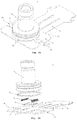
- Fig. 1 shows a simplified representation of a preferred embodiment of the stereo camera system according to the invention 1.
- the stereo camera system 1 comprises two camera modules 2, along an auxiliary device 3, which is used for alignment 1 of the camera modules 2, laterally offset and arranged with the same view 4 side by side.
- the auxiliary device 3 is arranged in particular for positioning the camera modules 2 in the stereo camera system 1 and removed after the positioning of the camera modules (2).
- the optical axes of the camera modules 2 are preferably aligned parallel to each other. Regardless of how the auxiliary device 3 is subsequently formed, the auxiliary device 3 comprises at least one reference edge 5.
- the stereo camera system 1 may be a system to be arranged in a vehicle.
- Such a stereo camera system 1 is usually arranged in the interior of the vehicle behind the windshield and with viewing direction 4 through the windshield.
- the camera modules 2 are usually arranged on a common line / axis parallel to the vehicle transverse axis and laterally offset side by side and aligned with their optical axes parallel to each other in the direction of the environment located in front of the vehicle.
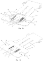
- the camera modules 2 of the stereo camera system 1 off Fig. 1 are preferably according to the FIGS. 2a to 2d educated.
- Fig. 2a shows a camera module 2 which can be arranged in the stereo camera system 1 according to the invention or which can be arranged in the context of the inventive method in a stereo camera system 1.
- Fig. 2b shows the camera module 2 off Fig. 2a in an exploded view.
- the Figures 2c and 2d show the camera module 2 according to the FIGS. 2a and 2b , but in each case without representation of the lens 11.
- the camera module 2 comprises according to the FIGS. 2a to 2d in each case an image pickup element 6, which is arranged on a carrier plate 7.
- the image pickup element 6 is preferably arranged on a front side of the carrier plate 7 and electrically contacted by wire bonds 8, in particular through recesses 9 in the carrier plate 7, with a printed circuit board 10 which is arranged on a rear side of the carrier plate 7.
- the image recording element 6 is preferably an unhoused image recording element, preferably a so-called bare die image chip, which is applied to the carrier plate 7.
- the support plate 7 may be made of metal.
- the printed circuit board 10 can be, for example, a flexible printed circuit board which carries components which are required for operating the image recording element 6 and in particular has a contact zone for connection to a zero-force plug. Alternatively, an FR4 printed circuit board could be used as a support plate 7.
- Such a printed circuit board 10 already has a flexible region with contact zones. Accordingly, the two-part solution, ie a separation of carrier and circuit board, would be omitted.
- the image pickup element 6 could be applied directly to the circuit board.
- the bond connection 9 would then take place on the same surface to which the image pickup element 6 is applied.
- the two-part design with separate support plate 7 and circuit board 10 has the significant advantage, especially if the support plate 7 is formed as a metal plate that a very good thermal connection of the image pickup element 6 is present.
- an objective 11 of the camera module 2 can be arranged directly on the carrier plate 7, for example by means of an adhesive bond 12.
- the support plate 7 comprises at least one reference outer edge 13.
- the reference outer edge 13 could in particular also be an inner edge 14 within a recess or within a cutout 15 in the Support plate 7 act. Basically, it is in addition to the use of reference outer edges 13 alternatively or additionally to use other special features, such as holes in the support plates 7, to align the support plates 7 and thus the camera modules 2 to each other
- the stereo camera system 1 off Fig. 1 For example, in a vehicle, behind the windshield, as viewed through the window, can be arranged.
- a stereo camera system 1 in a vehicle and in particular in a stereo camera system 1 according to Fig. 1 For example, to determine distance information or depth information, it is necessary that the camera modules 2 and the image pickup elements 6 of the stereo camera system 1 are aligned as closely as possible with respect to their distance, viewing direction 4 as well as their roll angle.
- the inventive method is used, in particular for aligning the roll angle of the image pickup elements 6 to each other.
Landscapes
- Physics & Mathematics (AREA)
- Engineering & Computer Science (AREA)
- Multimedia (AREA)
- Signal Processing (AREA)
- General Physics & Mathematics (AREA)
- Optics & Photonics (AREA)
- Studio Devices (AREA)
- Stereoscopic And Panoramic Photography (AREA)
- Testing, Inspecting, Measuring Of Stereoscopic Televisions And Televisions (AREA)
Applications Claiming Priority (2)
| Application Number | Priority Date | Filing Date | Title |
|---|---|---|---|
| DE102012106834.8A DE102012106834A1 (de) | 2012-07-27 | 2012-07-27 | Verfahren zur Ausrichtung zweier Bildaufnahmeelemente eines Stereokamerasystems |
| PCT/DE2013/200049 WO2014015867A1 (de) | 2012-07-27 | 2013-07-15 | Verfahren zur ausrichtung zweier bildaufnahmeelemente eines stereokamerasystems |
Publications (2)
| Publication Number | Publication Date |
|---|---|
| EP2877897A1 EP2877897A1 (de) | 2015-06-03 |
| EP2877897B1 true EP2877897B1 (de) | 2019-01-02 |
Family
ID=49084709
Family Applications (1)
| Application Number | Title | Priority Date | Filing Date |
|---|---|---|---|
| EP13755940.7A Active EP2877897B1 (de) | 2012-07-27 | 2013-07-15 | Verfahren zur ausrichtung zweier bildaufnahmeelemente eines stereokamerasystems |
Country Status (5)
| Country | Link |
|---|---|
| US (1) | US10547827B2 (enExample) |
| EP (1) | EP2877897B1 (enExample) |
| JP (1) | JP6608278B2 (enExample) |
| DE (2) | DE102012106834A1 (enExample) |
| WO (1) | WO2014015867A1 (enExample) |
Families Citing this family (11)
| Publication number | Priority date | Publication date | Assignee | Title |
|---|---|---|---|---|
| JP2016126243A (ja) * | 2015-01-07 | 2016-07-11 | 株式会社リコー | カメラ装置 |
| EP3068125A1 (en) * | 2015-03-09 | 2016-09-14 | Delphi Technologies, Inc. | A method of manufacturing a multiple view camera system and multiple view camera system |
| KR102130112B1 (ko) * | 2015-12-09 | 2020-07-03 | 타이탄 메디칼 아이엔씨. | 입체 영상화 센서 장치 및 입체 영상화에 사용되는 영상 센서의 쌍들을 제작하는 방법 |
| JP6591340B2 (ja) * | 2016-04-15 | 2019-10-16 | 日立オートモティブシステムズ株式会社 | 多眼光学装置 |
| JP6621716B2 (ja) * | 2016-08-02 | 2019-12-18 | 日立オートモティブシステムズ株式会社 | ステレオカメラ |
| DE102016217450B4 (de) | 2016-09-13 | 2025-10-16 | Aumovio Autonomous Mobility Germany Gmbh | Stereokameraanordnung für ein Kraftfahrzeug sowie Kraftfahrzeug mit einer solchen Stereokameraanordnung |
| JP6535646B2 (ja) * | 2016-10-21 | 2019-06-26 | 日立オートモティブシステムズ株式会社 | 撮像カメラおよび多眼撮像装置 |
| DE102017200817A1 (de) | 2017-01-19 | 2018-07-19 | Conti Temic Microelectronic Gmbh | Flexible leiterbahn zur verbindung elektronischer module, insbesondere von modulen einer für den einbau in ein fahrzeug vorgesehenen kamera |
| US10728435B2 (en) | 2017-06-23 | 2020-07-28 | Shoppertrak Rct Corporation | Image capture device with flexible circuit board |
| DE102017221474A1 (de) * | 2017-11-29 | 2019-05-29 | Robert Bosch Gmbh | Überwachungsmodul, Überwachungsmodulanordnung, Überwachungsanlage und Verfahren |
| WO2021121836A1 (en) * | 2019-12-19 | 2021-06-24 | Sony Semiconductor Solutions Corporation | A camera system for a mobile device, a method for localizing a camera and a method for localizing multiple cameras |
Family Cites Families (18)
| Publication number | Priority date | Publication date | Assignee | Title |
|---|---|---|---|---|
| ATE200050T1 (de) * | 1996-06-10 | 2001-04-15 | Guido Scheyer Sola Messwerkzeu | Vorrichtung zum ausrichten und festlegen von in einem gegenseitigen horizontalen oder vertikalen abstand zu liegen bestimmter befestigungsstellen von nägeln, stiften und haken sowie zum markieren von befestigungsstellen für wandplatten und einbauteilen im wohnungsbau |
| JP3750276B2 (ja) | 1997-05-23 | 2006-03-01 | ソニー株式会社 | 固体撮像素子の搭載方法および固体撮像素子パッケージの装着方法 |
| JP4115981B2 (ja) * | 2004-10-06 | 2008-07-09 | 本田技研工業株式会社 | 車両用ステレオカメラの取付構造 |
| EP2357527B1 (en) | 2004-11-15 | 2012-10-17 | Hitachi Ltd. | Stereo camera having two imaging elements mounted on a common stay |
| JP4275643B2 (ja) | 2005-04-19 | 2009-06-10 | 稔 稲葉 | ディジタルステレオカメラ又はディジタルステレオビデオカメラ |
| DE102006035232A1 (de) | 2006-07-26 | 2008-01-31 | Robert Bosch Gmbh | Optische Messeinrichtung mit einer Bildaufnahmeeinheit |
| JP4448844B2 (ja) | 2006-11-22 | 2010-04-14 | 富士フイルム株式会社 | 複眼撮像装置 |
| JP2009068906A (ja) * | 2007-09-11 | 2009-04-02 | Panasonic Corp | 距離測定装置 |
| US20100259655A1 (en) | 2007-11-01 | 2010-10-14 | Konica Minolta Holdings, Inc. | Imaging device |
| JP5324946B2 (ja) * | 2008-04-25 | 2013-10-23 | 富士重工業株式会社 | ステレオカメラユニット |
| JP2009265412A (ja) * | 2008-04-25 | 2009-11-12 | Fuji Heavy Ind Ltd | ステレオカメラユニット |
| US7848635B2 (en) * | 2008-05-28 | 2010-12-07 | Creat3 Inc. | Modular stereoscopic rig |
| DE102010010405A1 (de) * | 2010-03-05 | 2011-09-08 | Conti Temic Microelectronic Gmbh | Optische Vorrichtung und Verfahren zur Ausrichtung und Fixierung der optischen Vorrichtung |
| US8896671B2 (en) * | 2010-04-09 | 2014-11-25 | 3D-4U, Inc. | Apparatus and method for capturing images |
| US8610822B2 (en) * | 2010-04-19 | 2013-12-17 | Apple Inc. | Camera alignment and mounting structures |
| JP5158895B2 (ja) | 2010-05-11 | 2013-03-06 | シャープ株式会社 | 撮像装置 |
| DE102010023591A1 (de) | 2010-06-12 | 2011-12-15 | Conti Temic Microelectronic Gmbh | Stereokamerasystem |
| CN103140379A (zh) * | 2010-10-04 | 2013-06-05 | Tk控股公司 | 相机系统 |
-
2012
- 2012-07-27 DE DE102012106834.8A patent/DE102012106834A1/de not_active Withdrawn
-
2013
- 2013-07-15 JP JP2015523422A patent/JP6608278B2/ja active Active
- 2013-07-15 DE DE112013000212.4T patent/DE112013000212A5/de not_active Withdrawn
- 2013-07-15 WO PCT/DE2013/200049 patent/WO2014015867A1/de not_active Ceased
- 2013-07-15 US US14/379,593 patent/US10547827B2/en active Active
- 2013-07-15 EP EP13755940.7A patent/EP2877897B1/de active Active
Non-Patent Citations (1)
| Title |
|---|
| None * |
Also Published As
| Publication number | Publication date |
|---|---|
| JP6608278B2 (ja) | 2019-11-20 |
| EP2877897A1 (de) | 2015-06-03 |
| JP2015528133A (ja) | 2015-09-24 |
| WO2014015867A1 (de) | 2014-01-30 |
| US20150029313A1 (en) | 2015-01-29 |
| DE102012106834A1 (de) | 2014-01-30 |
| US10547827B2 (en) | 2020-01-28 |
| DE112013000212A5 (de) | 2014-09-18 |
Similar Documents
| Publication | Publication Date | Title |
|---|---|---|
| EP2877897B1 (de) | Verfahren zur ausrichtung zweier bildaufnahmeelemente eines stereokamerasystems | |
| EP1404545B1 (de) | Vorrichtung zur bilddetektion von gegenständen, personen oder dergleichen im umfeld eines fahrzeuges | |
| WO2014146629A1 (de) | Stereokameramodul sowie verfahren zu dessen herstellung | |
| DE102012001554A1 (de) | Verfahren zum Betreiben einer Fahrerassistenzeinrichtung eines Kraftfahrzeugs,Fahrerassistenzeinrichtung und Kraftfahrzeug | |
| DE112018004595B4 (de) | Fahrzeuginterne bildaufnahmevorrichtung | |
| DE112013003795T5 (de) | In ein Fahrzeug eingebaute Bildverarbeitungsvorrichtung | |
| WO2010103061A1 (de) | Vorrichtung und verfahren zur detektion mindestens eines objektes | |
| DE102012105436B4 (de) | Fahrzeugkamera zur Entfernungsmessung | |
| DE112020005641T5 (de) | Bildgebungsvorrichtung | |
| EP2715279A1 (de) | Vorrichtung und verfahren zur fahrwerksvermessung eines kraftfahrzeugs | |
| WO2019214973A1 (de) | Lidar messsystem und verfahren zur montage eines lidar messsystems | |
| DE112022003481T5 (de) | Fahrzeugvorrichtung und fahrzeugsteuerungsverfahren | |
| WO2019158166A2 (de) | Telekamera für ein fahrzeug sowie befestigung einer telekamera am fahrzeug | |
| DE102014208487B4 (de) | Kamera eines Assistenzsystems eines Kraftfahrzeugs sowie Verfahren zur Herstellung eines derartigen Assistenzsystems | |
| WO2011131164A1 (de) | Optische vorrichtung und verfahren zur positionierung eines optischen elements über einem bildaufnahmeelement | |
| DE102012105435B4 (de) | Fahrzeugkamera zur Entfernungsmessung | |
| DE102017219688A1 (de) | Verfahren zur Kalibrierung einer Fahrzeugkamera | |
| DE102019200099A1 (de) | Sensorvorrichtung für ein Ego-Fahrzeug, Fahrerassistenzvorrichtung und Fahrzeug mit einer solchen Sensorvorrichtung | |
| EP2565580B1 (de) | Verfahren zur Bestimmung eines Ausmaßes eines Objekts in einer Umgebung eines Fahrzeugs sowie eine entsprechende Vorrichtung und ein Fahrzeug mit einer derartigen Vorrichtung | |
| DE102013102207A1 (de) | Kamerasystem für ein Fahrzeug | |
| DE102018207297A1 (de) | LIDAR Messsystem und Verfahren zur Montage eines LIDAR Messsystems | |
| DE102020214622A1 (de) | Auswertung von Bilddaten einer Stereokamera zur Objektbewertung | |
| DE102016212730A1 (de) | Fahrzeugkameravorrichtung mit Bildauswertungselektronik | |
| DE102021207211B4 (de) | Lagerungskonzept für einen Sensor zur Umfelderfassung eines Fahrzeugs | |
| DE102014220558A1 (de) | Bilderfassungsvorrichtung für ein fahrzeug und verfahren |
Legal Events
| Date | Code | Title | Description |
|---|---|---|---|
| PUAI | Public reference made under article 153(3) epc to a published international application that has entered the european phase |
Free format text: ORIGINAL CODE: 0009012 |
|
| 17P | Request for examination filed |
Effective date: 20150227 |
|
| AK | Designated contracting states |
Kind code of ref document: A1 Designated state(s): AL AT BE BG CH CY CZ DE DK EE ES FI FR GB GR HR HU IE IS IT LI LT LU LV MC MK MT NL NO PL PT RO RS SE SI SK SM TR |
|
| AX | Request for extension of the european patent |
Extension state: BA ME |
|
| DAX | Request for extension of the european patent (deleted) | ||
| STAA | Information on the status of an ep patent application or granted ep patent |
Free format text: STATUS: EXAMINATION IS IN PROGRESS |
|
| 17Q | First examination report despatched |
Effective date: 20170613 |
|
| GRAP | Despatch of communication of intention to grant a patent |
Free format text: ORIGINAL CODE: EPIDOSNIGR1 |
|
| STAA | Information on the status of an ep patent application or granted ep patent |
Free format text: STATUS: GRANT OF PATENT IS INTENDED |
|
| INTG | Intention to grant announced |
Effective date: 20180907 |
|
| GRAS | Grant fee paid |
Free format text: ORIGINAL CODE: EPIDOSNIGR3 |
|
| GRAA | (expected) grant |
Free format text: ORIGINAL CODE: 0009210 |
|
| STAA | Information on the status of an ep patent application or granted ep patent |
Free format text: STATUS: THE PATENT HAS BEEN GRANTED |
|
| AK | Designated contracting states |
Kind code of ref document: B1 Designated state(s): AL AT BE BG CH CY CZ DE DK EE ES FI FR GB GR HR HU IE IS IT LI LT LU LV MC MK MT NL NO PL PT RO RS SE SI SK SM TR |
|
| REG | Reference to a national code |
Ref country code: GB Ref legal event code: FG4D Free format text: NOT ENGLISH |
|
| REG | Reference to a national code |
Ref country code: CH Ref legal event code: EP Ref country code: AT Ref legal event code: REF Ref document number: 1085153 Country of ref document: AT Kind code of ref document: T Effective date: 20190115 |
|
| REG | Reference to a national code |
Ref country code: IE Ref legal event code: FG4D Free format text: LANGUAGE OF EP DOCUMENT: GERMAN |
|
| REG | Reference to a national code |
Ref country code: DE Ref legal event code: R096 Ref document number: 502013011968 Country of ref document: DE |
|
| REG | Reference to a national code |
Ref country code: NL Ref legal event code: MP Effective date: 20190102 |
|
| REG | Reference to a national code |
Ref country code: LT Ref legal event code: MG4D |
|
| PG25 | Lapsed in a contracting state [announced via postgrant information from national office to epo] |
Ref country code: NL Free format text: LAPSE BECAUSE OF FAILURE TO SUBMIT A TRANSLATION OF THE DESCRIPTION OR TO PAY THE FEE WITHIN THE PRESCRIBED TIME-LIMIT Effective date: 20190102 |
|
| PG25 | Lapsed in a contracting state [announced via postgrant information from national office to epo] |
Ref country code: PT Free format text: LAPSE BECAUSE OF FAILURE TO SUBMIT A TRANSLATION OF THE DESCRIPTION OR TO PAY THE FEE WITHIN THE PRESCRIBED TIME-LIMIT Effective date: 20190502 Ref country code: ES Free format text: LAPSE BECAUSE OF FAILURE TO SUBMIT A TRANSLATION OF THE DESCRIPTION OR TO PAY THE FEE WITHIN THE PRESCRIBED TIME-LIMIT Effective date: 20190102 Ref country code: SE Free format text: LAPSE BECAUSE OF FAILURE TO SUBMIT A TRANSLATION OF THE DESCRIPTION OR TO PAY THE FEE WITHIN THE PRESCRIBED TIME-LIMIT Effective date: 20190102 Ref country code: PL Free format text: LAPSE BECAUSE OF FAILURE TO SUBMIT A TRANSLATION OF THE DESCRIPTION OR TO PAY THE FEE WITHIN THE PRESCRIBED TIME-LIMIT Effective date: 20190102 Ref country code: NO Free format text: LAPSE BECAUSE OF FAILURE TO SUBMIT A TRANSLATION OF THE DESCRIPTION OR TO PAY THE FEE WITHIN THE PRESCRIBED TIME-LIMIT Effective date: 20190402 Ref country code: LT Free format text: LAPSE BECAUSE OF FAILURE TO SUBMIT A TRANSLATION OF THE DESCRIPTION OR TO PAY THE FEE WITHIN THE PRESCRIBED TIME-LIMIT Effective date: 20190102 Ref country code: FI Free format text: LAPSE BECAUSE OF FAILURE TO SUBMIT A TRANSLATION OF THE DESCRIPTION OR TO PAY THE FEE WITHIN THE PRESCRIBED TIME-LIMIT Effective date: 20190102 |
|
| PG25 | Lapsed in a contracting state [announced via postgrant information from national office to epo] |
Ref country code: GR Free format text: LAPSE BECAUSE OF FAILURE TO SUBMIT A TRANSLATION OF THE DESCRIPTION OR TO PAY THE FEE WITHIN THE PRESCRIBED TIME-LIMIT Effective date: 20190403 Ref country code: BG Free format text: LAPSE BECAUSE OF FAILURE TO SUBMIT A TRANSLATION OF THE DESCRIPTION OR TO PAY THE FEE WITHIN THE PRESCRIBED TIME-LIMIT Effective date: 20190402 Ref country code: RS Free format text: LAPSE BECAUSE OF FAILURE TO SUBMIT A TRANSLATION OF THE DESCRIPTION OR TO PAY THE FEE WITHIN THE PRESCRIBED TIME-LIMIT Effective date: 20190102 Ref country code: HR Free format text: LAPSE BECAUSE OF FAILURE TO SUBMIT A TRANSLATION OF THE DESCRIPTION OR TO PAY THE FEE WITHIN THE PRESCRIBED TIME-LIMIT Effective date: 20190102 Ref country code: IS Free format text: LAPSE BECAUSE OF FAILURE TO SUBMIT A TRANSLATION OF THE DESCRIPTION OR TO PAY THE FEE WITHIN THE PRESCRIBED TIME-LIMIT Effective date: 20190502 Ref country code: LV Free format text: LAPSE BECAUSE OF FAILURE TO SUBMIT A TRANSLATION OF THE DESCRIPTION OR TO PAY THE FEE WITHIN THE PRESCRIBED TIME-LIMIT Effective date: 20190102 |
|
| REG | Reference to a national code |
Ref country code: DE Ref legal event code: R097 Ref document number: 502013011968 Country of ref document: DE |
|
| PG25 | Lapsed in a contracting state [announced via postgrant information from national office to epo] |
Ref country code: SK Free format text: LAPSE BECAUSE OF FAILURE TO SUBMIT A TRANSLATION OF THE DESCRIPTION OR TO PAY THE FEE WITHIN THE PRESCRIBED TIME-LIMIT Effective date: 20190102 Ref country code: IT Free format text: LAPSE BECAUSE OF FAILURE TO SUBMIT A TRANSLATION OF THE DESCRIPTION OR TO PAY THE FEE WITHIN THE PRESCRIBED TIME-LIMIT Effective date: 20190102 Ref country code: RO Free format text: LAPSE BECAUSE OF FAILURE TO SUBMIT A TRANSLATION OF THE DESCRIPTION OR TO PAY THE FEE WITHIN THE PRESCRIBED TIME-LIMIT Effective date: 20190102 Ref country code: EE Free format text: LAPSE BECAUSE OF FAILURE TO SUBMIT A TRANSLATION OF THE DESCRIPTION OR TO PAY THE FEE WITHIN THE PRESCRIBED TIME-LIMIT Effective date: 20190102 Ref country code: AL Free format text: LAPSE BECAUSE OF FAILURE TO SUBMIT A TRANSLATION OF THE DESCRIPTION OR TO PAY THE FEE WITHIN THE PRESCRIBED TIME-LIMIT Effective date: 20190102 Ref country code: DK Free format text: LAPSE BECAUSE OF FAILURE TO SUBMIT A TRANSLATION OF THE DESCRIPTION OR TO PAY THE FEE WITHIN THE PRESCRIBED TIME-LIMIT Effective date: 20190102 Ref country code: CZ Free format text: LAPSE BECAUSE OF FAILURE TO SUBMIT A TRANSLATION OF THE DESCRIPTION OR TO PAY THE FEE WITHIN THE PRESCRIBED TIME-LIMIT Effective date: 20190102 |
|
| PLBE | No opposition filed within time limit |
Free format text: ORIGINAL CODE: 0009261 |
|
| STAA | Information on the status of an ep patent application or granted ep patent |
Free format text: STATUS: NO OPPOSITION FILED WITHIN TIME LIMIT |
|
| PG25 | Lapsed in a contracting state [announced via postgrant information from national office to epo] |
Ref country code: SM Free format text: LAPSE BECAUSE OF FAILURE TO SUBMIT A TRANSLATION OF THE DESCRIPTION OR TO PAY THE FEE WITHIN THE PRESCRIBED TIME-LIMIT Effective date: 20190102 |
|
| 26N | No opposition filed |
Effective date: 20191003 |
|
| PG25 | Lapsed in a contracting state [announced via postgrant information from national office to epo] |
Ref country code: MC Free format text: LAPSE BECAUSE OF FAILURE TO SUBMIT A TRANSLATION OF THE DESCRIPTION OR TO PAY THE FEE WITHIN THE PRESCRIBED TIME-LIMIT Effective date: 20190102 Ref country code: SI Free format text: LAPSE BECAUSE OF FAILURE TO SUBMIT A TRANSLATION OF THE DESCRIPTION OR TO PAY THE FEE WITHIN THE PRESCRIBED TIME-LIMIT Effective date: 20190102 |
|
| REG | Reference to a national code |
Ref country code: CH Ref legal event code: PL |
|
| GBPC | Gb: european patent ceased through non-payment of renewal fee |
Effective date: 20190715 |
|
| PG25 | Lapsed in a contracting state [announced via postgrant information from national office to epo] |
Ref country code: TR Free format text: LAPSE BECAUSE OF FAILURE TO SUBMIT A TRANSLATION OF THE DESCRIPTION OR TO PAY THE FEE WITHIN THE PRESCRIBED TIME-LIMIT Effective date: 20190102 |
|
| REG | Reference to a national code |
Ref country code: BE Ref legal event code: MM Effective date: 20190731 |
|
| PG25 | Lapsed in a contracting state [announced via postgrant information from national office to epo] |
Ref country code: GB Free format text: LAPSE BECAUSE OF NON-PAYMENT OF DUE FEES Effective date: 20190715 |
|
| PG25 | Lapsed in a contracting state [announced via postgrant information from national office to epo] |
Ref country code: LI Free format text: LAPSE BECAUSE OF NON-PAYMENT OF DUE FEES Effective date: 20190731 Ref country code: CH Free format text: LAPSE BECAUSE OF NON-PAYMENT OF DUE FEES Effective date: 20190731 Ref country code: LU Free format text: LAPSE BECAUSE OF NON-PAYMENT OF DUE FEES Effective date: 20190715 Ref country code: BE Free format text: LAPSE BECAUSE OF NON-PAYMENT OF DUE FEES Effective date: 20190731 |
|
| PG25 | Lapsed in a contracting state [announced via postgrant information from national office to epo] |
Ref country code: FR Free format text: LAPSE BECAUSE OF NON-PAYMENT OF DUE FEES Effective date: 20190731 |
|
| PG25 | Lapsed in a contracting state [announced via postgrant information from national office to epo] |
Ref country code: IE Free format text: LAPSE BECAUSE OF NON-PAYMENT OF DUE FEES Effective date: 20190715 |
|
| REG | Reference to a national code |
Ref country code: AT Ref legal event code: MM01 Ref document number: 1085153 Country of ref document: AT Kind code of ref document: T Effective date: 20190715 |
|
| PG25 | Lapsed in a contracting state [announced via postgrant information from national office to epo] |
Ref country code: AT Free format text: LAPSE BECAUSE OF NON-PAYMENT OF DUE FEES Effective date: 20190715 |
|
| PG25 | Lapsed in a contracting state [announced via postgrant information from national office to epo] |
Ref country code: CY Free format text: LAPSE BECAUSE OF FAILURE TO SUBMIT A TRANSLATION OF THE DESCRIPTION OR TO PAY THE FEE WITHIN THE PRESCRIBED TIME-LIMIT Effective date: 20190102 |
|
| PG25 | Lapsed in a contracting state [announced via postgrant information from national office to epo] |
Ref country code: HU Free format text: LAPSE BECAUSE OF FAILURE TO SUBMIT A TRANSLATION OF THE DESCRIPTION OR TO PAY THE FEE WITHIN THE PRESCRIBED TIME-LIMIT; INVALID AB INITIO Effective date: 20130715 Ref country code: MT Free format text: LAPSE BECAUSE OF FAILURE TO SUBMIT A TRANSLATION OF THE DESCRIPTION OR TO PAY THE FEE WITHIN THE PRESCRIBED TIME-LIMIT Effective date: 20190102 |
|
| REG | Reference to a national code |
Ref country code: DE Ref legal event code: R081 Ref document number: 502013011968 Country of ref document: DE Owner name: CONTINENTAL AUTONOMOUS MOBILITY GERMANY GMBH, DE Free format text: FORMER OWNER: CONTI TEMIC MICROELECTRONIC GMBH, 90411 NUERNBERG, DE Ref country code: DE Ref legal event code: R081 Ref document number: 502013011968 Country of ref document: DE Owner name: AUMOVIO AUTONOMOUS MOBILITY GERMANY GMBH, DE Free format text: FORMER OWNER: CONTI TEMIC MICROELECTRONIC GMBH, 90411 NUERNBERG, DE |
|
| PG25 | Lapsed in a contracting state [announced via postgrant information from national office to epo] |
Ref country code: MK Free format text: LAPSE BECAUSE OF FAILURE TO SUBMIT A TRANSLATION OF THE DESCRIPTION OR TO PAY THE FEE WITHIN THE PRESCRIBED TIME-LIMIT Effective date: 20190102 |
|
| REG | Reference to a national code |
Ref country code: DE Ref legal event code: R081 Ref document number: 502013011968 Country of ref document: DE Owner name: AUMOVIO AUTONOMOUS MOBILITY GERMANY GMBH, DE Free format text: FORMER OWNER: CONTINENTAL AUTONOMOUS MOBILITY GERMANY GMBH, 85057 INGOLSTADT, DE |
|
| PGFP | Annual fee paid to national office [announced via postgrant information from national office to epo] |
Ref country code: DE Payment date: 20250731 Year of fee payment: 13 |