EP2876385A2 - Climatiseur - Google Patents
Climatiseur Download PDFInfo
- Publication number
- EP2876385A2 EP2876385A2 EP14194580.8A EP14194580A EP2876385A2 EP 2876385 A2 EP2876385 A2 EP 2876385A2 EP 14194580 A EP14194580 A EP 14194580A EP 2876385 A2 EP2876385 A2 EP 2876385A2
- Authority
- EP
- European Patent Office
- Prior art keywords
- controller
- refrigerant pipe
- refrigerant
- expansion valve
- electronic expansion
- Prior art date
- Legal status (The legal status is an assumption and is not a legal conclusion. Google has not performed a legal analysis and makes no representation as to the accuracy of the status listed.)
- Granted
Links
- 239000003507 refrigerant Substances 0.000 claims abstract description 259
- 230000005494 condensation Effects 0.000 claims abstract description 78
- 238000009833 condensation Methods 0.000 claims abstract description 78
- 238000001816 cooling Methods 0.000 claims abstract description 66
- 238000005057 refrigeration Methods 0.000 claims abstract description 26
- 238000010438 heat treatment Methods 0.000 claims description 28
- 230000002265 prevention Effects 0.000 claims description 12
- 230000002441 reversible effect Effects 0.000 claims description 10
- 239000007788 liquid Substances 0.000 abstract description 39
- 230000015572 biosynthetic process Effects 0.000 abstract description 12
- 230000001965 increasing effect Effects 0.000 description 13
- 230000007423 decrease Effects 0.000 description 12
- 229910052782 aluminium Inorganic materials 0.000 description 7
- XAGFODPZIPBFFR-UHFFFAOYSA-N aluminium Chemical compound [Al] XAGFODPZIPBFFR-UHFFFAOYSA-N 0.000 description 7
- 230000004048 modification Effects 0.000 description 5
- 238000012986 modification Methods 0.000 description 5
- 238000010586 diagram Methods 0.000 description 4
- 230000000694 effects Effects 0.000 description 3
- 239000004519 grease Substances 0.000 description 3
- 229910052751 metal Inorganic materials 0.000 description 3
- 239000002184 metal Substances 0.000 description 3
- 230000002708 enhancing effect Effects 0.000 description 2
- 238000007710 freezing Methods 0.000 description 2
- 230000008014 freezing Effects 0.000 description 2
- 230000008878 coupling Effects 0.000 description 1
- 238000010168 coupling process Methods 0.000 description 1
- 238000005859 coupling reaction Methods 0.000 description 1
- 238000009434 installation Methods 0.000 description 1
Images


Classifications
-
- F—MECHANICAL ENGINEERING; LIGHTING; HEATING; WEAPONS; BLASTING
- F25—REFRIGERATION OR COOLING; COMBINED HEATING AND REFRIGERATION SYSTEMS; HEAT PUMP SYSTEMS; MANUFACTURE OR STORAGE OF ICE; LIQUEFACTION SOLIDIFICATION OF GASES
- F25B—REFRIGERATION MACHINES, PLANTS OR SYSTEMS; COMBINED HEATING AND REFRIGERATION SYSTEMS; HEAT PUMP SYSTEMS
- F25B49/00—Arrangement or mounting of control or safety devices
- F25B49/02—Arrangement or mounting of control or safety devices for compression type machines, plants or systems
-
- F—MECHANICAL ENGINEERING; LIGHTING; HEATING; WEAPONS; BLASTING
- F25—REFRIGERATION OR COOLING; COMBINED HEATING AND REFRIGERATION SYSTEMS; HEAT PUMP SYSTEMS; MANUFACTURE OR STORAGE OF ICE; LIQUEFACTION SOLIDIFICATION OF GASES
- F25B—REFRIGERATION MACHINES, PLANTS OR SYSTEMS; COMBINED HEATING AND REFRIGERATION SYSTEMS; HEAT PUMP SYSTEMS
- F25B31/00—Compressor arrangements
- F25B31/006—Cooling of compressor or motor
-
- F—MECHANICAL ENGINEERING; LIGHTING; HEATING; WEAPONS; BLASTING
- F25—REFRIGERATION OR COOLING; COMBINED HEATING AND REFRIGERATION SYSTEMS; HEAT PUMP SYSTEMS; MANUFACTURE OR STORAGE OF ICE; LIQUEFACTION SOLIDIFICATION OF GASES
- F25B—REFRIGERATION MACHINES, PLANTS OR SYSTEMS; COMBINED HEATING AND REFRIGERATION SYSTEMS; HEAT PUMP SYSTEMS
- F25B13/00—Compression machines, plants or systems, with reversible cycle
-
- F—MECHANICAL ENGINEERING; LIGHTING; HEATING; WEAPONS; BLASTING
- F25—REFRIGERATION OR COOLING; COMBINED HEATING AND REFRIGERATION SYSTEMS; HEAT PUMP SYSTEMS; MANUFACTURE OR STORAGE OF ICE; LIQUEFACTION SOLIDIFICATION OF GASES
- F25B—REFRIGERATION MACHINES, PLANTS OR SYSTEMS; COMBINED HEATING AND REFRIGERATION SYSTEMS; HEAT PUMP SYSTEMS
- F25B2313/00—Compression machines, plants or systems with reversible cycle not otherwise provided for
- F25B2313/029—Control issues
- F25B2313/0293—Control issues related to the indoor fan, e.g. controlling speed
-
- F—MECHANICAL ENGINEERING; LIGHTING; HEATING; WEAPONS; BLASTING
- F25—REFRIGERATION OR COOLING; COMBINED HEATING AND REFRIGERATION SYSTEMS; HEAT PUMP SYSTEMS; MANUFACTURE OR STORAGE OF ICE; LIQUEFACTION SOLIDIFICATION OF GASES
- F25B—REFRIGERATION MACHINES, PLANTS OR SYSTEMS; COMBINED HEATING AND REFRIGERATION SYSTEMS; HEAT PUMP SYSTEMS
- F25B2313/00—Compression machines, plants or systems with reversible cycle not otherwise provided for
- F25B2313/029—Control issues
- F25B2313/0294—Control issues related to the outdoor fan, e.g. controlling speed
-
- F—MECHANICAL ENGINEERING; LIGHTING; HEATING; WEAPONS; BLASTING
- F25—REFRIGERATION OR COOLING; COMBINED HEATING AND REFRIGERATION SYSTEMS; HEAT PUMP SYSTEMS; MANUFACTURE OR STORAGE OF ICE; LIQUEFACTION SOLIDIFICATION OF GASES
- F25B—REFRIGERATION MACHINES, PLANTS OR SYSTEMS; COMBINED HEATING AND REFRIGERATION SYSTEMS; HEAT PUMP SYSTEMS
- F25B2313/00—Compression machines, plants or systems with reversible cycle not otherwise provided for
- F25B2313/031—Sensor arrangements
- F25B2313/0314—Temperature sensors near the indoor heat exchanger
-
- F—MECHANICAL ENGINEERING; LIGHTING; HEATING; WEAPONS; BLASTING
- F25—REFRIGERATION OR COOLING; COMBINED HEATING AND REFRIGERATION SYSTEMS; HEAT PUMP SYSTEMS; MANUFACTURE OR STORAGE OF ICE; LIQUEFACTION SOLIDIFICATION OF GASES
- F25B—REFRIGERATION MACHINES, PLANTS OR SYSTEMS; COMBINED HEATING AND REFRIGERATION SYSTEMS; HEAT PUMP SYSTEMS
- F25B2313/00—Compression machines, plants or systems with reversible cycle not otherwise provided for
- F25B2313/031—Sensor arrangements
- F25B2313/0315—Temperature sensors near the outdoor heat exchanger
-
- F—MECHANICAL ENGINEERING; LIGHTING; HEATING; WEAPONS; BLASTING
- F25—REFRIGERATION OR COOLING; COMBINED HEATING AND REFRIGERATION SYSTEMS; HEAT PUMP SYSTEMS; MANUFACTURE OR STORAGE OF ICE; LIQUEFACTION SOLIDIFICATION OF GASES
- F25B—REFRIGERATION MACHINES, PLANTS OR SYSTEMS; COMBINED HEATING AND REFRIGERATION SYSTEMS; HEAT PUMP SYSTEMS
- F25B2600/00—Control issues
- F25B2600/02—Compressor control
- F25B2600/025—Compressor control by controlling speed
- F25B2600/0253—Compressor control by controlling speed with variable speed
-
- F—MECHANICAL ENGINEERING; LIGHTING; HEATING; WEAPONS; BLASTING
- F25—REFRIGERATION OR COOLING; COMBINED HEATING AND REFRIGERATION SYSTEMS; HEAT PUMP SYSTEMS; MANUFACTURE OR STORAGE OF ICE; LIQUEFACTION SOLIDIFICATION OF GASES
- F25B—REFRIGERATION MACHINES, PLANTS OR SYSTEMS; COMBINED HEATING AND REFRIGERATION SYSTEMS; HEAT PUMP SYSTEMS
- F25B2600/00—Control issues
- F25B2600/25—Control of valves
- F25B2600/2513—Expansion valves
-
- Y—GENERAL TAGGING OF NEW TECHNOLOGICAL DEVELOPMENTS; GENERAL TAGGING OF CROSS-SECTIONAL TECHNOLOGIES SPANNING OVER SEVERAL SECTIONS OF THE IPC; TECHNICAL SUBJECTS COVERED BY FORMER USPC CROSS-REFERENCE ART COLLECTIONS [XRACs] AND DIGESTS
- Y02—TECHNOLOGIES OR APPLICATIONS FOR MITIGATION OR ADAPTATION AGAINST CLIMATE CHANGE
- Y02B—CLIMATE CHANGE MITIGATION TECHNOLOGIES RELATED TO BUILDINGS, e.g. HOUSING, HOUSE APPLIANCES OR RELATED END-USER APPLICATIONS
- Y02B30/00—Energy efficient heating, ventilation or air conditioning [HVAC]
- Y02B30/70—Efficient control or regulation technologies, e.g. for control of refrigerant flow, motor or heating
Definitions
- the present invention relates to an air conditioner in which a controller can be cooled by using a refrigerant pipe that constitutes a refrigeration cycle.
- Patent Literature 1 provides a system in which a casing accommodating electronic components is thermally coupled with a refrigerant pipe via a cooling jacket interposed therebetween.
- Patent Literature 1 discloses a system in which a controller is cooled by thermally coupling the casing of the controller with refrigerant pipes (1) to (4) described below.
- the controller is cooled by using a refrigerant pipe between the outdoor heat exchanger and the expansion valve, that is, by means of the high-pressure liquid refrigerant during cooling operation and the low-pressure two-phase refrigerant during heating operation, when frost forms on the refrigerant pipe during heating operation at a low outdoor air temperature, there is a risk of the pipe being damaged due to freezing caused by the frost formation, malfunctioning occurring, the electronic components being damaged, or the like, due to the drain liquid from the frost dripping onto electronic components provided in the controller.
- the refrigerant pipe is thermally coupled with the casing of the controller with an aluminum cooling jacket interposed therebetween, it is difficult to couple the aluminum cooling jacket and the refrigerant pipe by bringing them into close contact on an assembly line, and thus, they are brought into close contact by applying grease or the like; however there is a problem in that, among others, working on the assembly line while managing the amount of grease to be applied requires complicated tasks.
- the present invention has been conceived in light of the above-described circumstances and provides an air conditioner with which it is possible to eliminate the occurrence of condensation when cooling a controller during cooling operation by using a refrigerant pipe in which low-pressure two-phase refrigerant flows, with which it is also possible, even if condensation or frost formation occurs on the refrigerant pipe, to prevent malfunctioning of the controller, damage to electronic components, or the like, due to the drain liquid from condensation or frost dripping thereonto, and, additionally, with which it is possible to easily place the refrigerant pipe in close contact with the controller.
- an air conditioner of the present invention employs the following solutions.
- a first aspect of the present invention is an air conditioner equipped with a reversible refrigeration cycle in which a compressor, a four-way switching valve, an outdoor heat exchanger, an electronic expansion valve, and an indoor heat exchanger are connected by using refrigerant pipes and a controller that is cooled during cooling operation by being in contact with a refrigerant pipe in which low-pressure two-phase refrigerant whose flow rate is reduced at the electronic expansion valve flows, the air conditioner including a condensation-prevention control portion that, when a condition for condensation to occur on the refrigerant pipe that cools the controller is detected, prevents the occurrence of condensation by means of any one of rotational-speed control of an indoor fan, rotational-speed control of an outdoor fan, degree-of-opening control of the electronic expansion valve, and rotational-speed control of the compressor.
- the condensation-prevention control portion is provided which, when the condition for condensation to occur on the refrigerant pipe that cools the controller is detected, prevents the occurrence of condensation by means of any one of the rotational-speed control of an indoor fan, the rotational-speed control of an outdoor fan, the degree-of-opening control of the electronic expansion valve, and the rotational-speed control of the compressor.
- the occurrence of condensation on the refrigerant pipe when the condition for condensation to occur is detected can be prevented by increasing the refrigerant temperature by performing any one of the rotational-speed control of an indoor fan, the rotational-speed control of an outdoor fan, the degree-of-opening control of the electronic expansion valve, and the rotational-speed control of the compressor by means of the condensation-prevention control portion. Therefore, it is possible to enhance the product quality and reliability by increasing the cooling performance for cooling heat-generating components while preventing the occurrence of malfunctioning, damage to electronic components, or the like, due to drain liquid dripping onto the controller.
- the condensation-prevention control portion when performing the control for preventing the occurrence of condensation, with reference to a refrigerant temperature that is set in advance in accordance with the outdoor air temperature or a target temperature of a substitute temperature thereof, the condensation-prevention control portion may sequentially perform the condensation prevention control in which the rotational-speed control of an indoor fan, the rotational-speed control of an outdoor fan, the degree-of-opening control of the electronic expansion valve, and the rotational-speed control of the compressor are performed in this sequence.
- the condensation-prevention control portion sequentially performs the condensation prevention control in which the rotational-speed control of the indoor fan, the rotational-speed control of the outdoor fan, the degree-of-opening control of the electronic expansion valve, and the rotational-speed control of the compressor are performed in this sequence.
- a second aspect of the present invention is an air conditioner equipped with a reversible refrigeration cycle in which a compressor, a four-way switching valve, an outdoor heat exchanger, an electronic expansion valve, and an indoor heat exchanger are connected by using refrigerant pipes and a controller that is cooled during cooling operation or during heating operation by being in contact with a refrigerant pipe in which low-pressure refrigerant whose flow rate is reduced at the electronic expansion valve flows, wherein the refrigerant pipe is placed against a heat-generating component of the controller via a heat-conducting block; the heat-conducting block is divided into two parts, namely, a first block that is placed in contact with the heat-generating component and a second block that is placed in contact with the refrigerant pipe; and the two divided parts, that is, the first block and the second block, can be assembled into a single block.
- the air conditioner in the air conditioner provided with the controller that is cooled during cooling operation or during heating operation by being in contact with the refrigerant pipe in which the low-pressure refrigerant whose flow rate is reduced at the expansion valve flows, the refrigerant pipe is placed against the heat-generating components of the controller via the heat-conducting block, the heat-conducting block is divided into two parts, namely, the first block that is placed in contact with the heat-generating components and the second block that is placed in contact with the refrigerant pipe, and the two divided parts, that is, the first block and the second block, can be assembled into a single unit.
- the second block may be provided with a semicircular groove along which the refrigerant pipe is placed.
- the second block is provided with the semicircular groove along which the refrigerant pipe is placed, by placing the refrigerant pipe along the semicircular groove in the second block and by securing them via a pressing metal fitting or the like, it is possible to reliably place the refrigerant pipe in close contact with the second block. Therefore, it is possible to increase the heat conducting efficiency between the refrigerant pipe and the heat-conducting block, and, consequently, between the refrigerant pipe and the controller, which makes it possible to further enhance the cooling performance for cooling the controller and the heat-generating components thereof.
- a third aspect of the present invention is an air conditioner equipped with a reversible refrigeration cycle in which a compressor, a four-way switching valve, an outdoor heat exchanger, an electronic expansion valve, and an indoor heat exchanger are connected by using refrigerant pipes and a controller that is cooled during cooling operation or during heating operation by being in contact with a refrigerant pipe in which low-pressure refrigerant whose flow rate is reduced at the electronic expansion valve flows, wherein the refrigerant pipe is placed at an angle with respect to the controller.
- the refrigerant pipe is placed at an angle with respect to the controller. Because of this, even if condensation or frost formation occurs on the surface of the refrigerant pipe depending on the operating state, the drain liquid from the condensation or frost can quickly be expelled in a specific direction along the inclination of the refrigerant pipe that is placed at an angle. Therefore, it is possible to prevent the drain liquid from remaining on the controller, and it is also possible to protect the controller by preventing the occurrence of malfunctioning, damage to the electronic components, or the like, due to the drain liquid dripping onto the electronic components.
- a fourth aspect of the present invention is an air conditioner equipped with a reversible refrigeration cycle in which a compressor, a four-way switching valve, an outdoor heat exchanger, an electronic expansion valve, and an indoor heat exchanger are connected by using refrigerant pipes and a controller that is cooled during cooling operation or during heating operation by being in contact with a refrigerant pipe in which low-pressure refrigerant whose flow rate is reduced at the electronic expansion valve flows, wherein heat-generating components in the controller are placed so as to be concentrated in a lower portion of the controller, and the refrigerant pipe is placed in contact with this lower portion.
- a first modification of the present invention is an air conditioner equipped with a refrigeration cycle in which a compressor, an outdoor heat exchanger, an electronic expansion valve, and an indoor heat exchanger are connected by using refrigerant pipes and a controller that is cooled by being in contact with a refrigerant pipe in which low-pressure two-phase refrigerant whose flow rate is reduced at the electronic expansion valve flows, the air conditioner including a condensation-prevention control portion that, when a condition for condensation to occur on the refrigerant pipe that cools the controller is detected, prevents the occurrence of condensation by means of any one of rotational-speed control of an indoor fan, rotational-speed control of an outdoor fan, degree-of-opening control of the electronic expansion valve, and rotational-speed control of the compressor.
- a second modification of the present invention is an air conditioner equipped with a refrigeration cycle in which a compressor, an outdoor heat exchanger, an electronic expansion valve, and an indoor heat exchanger are connected by using refrigerant pipes and a controller that is cooled by being in contact with a refrigerant pipe in which low-pressure refrigerant whose flow rate is reduced at the electronic expansion valve flows, wherein the refrigerant pipe is placed against a heat-generating component of the controller via a heat-conducting block; the heat-conducting block is divided into two parts, namely, a first block that is placed in contact with the heat-generating component and a second block that is placed in contact with the refrigerant pipe; and the two divided parts, that is, the first block and the second block, can be assembled into a single block.
- a third modification of the present invention is an air conditioner equipped with a refrigeration cycle in which a compressor, an outdoor heat exchanger, an electronic expansion valve, and an indoor heat exchanger are connected by using refrigerant pipes and a controller that is cooled by being in contact with a refrigerant pipe in which low-pressure refrigerant whose flow rate is reduced at the electronic expansion valve flows, wherein the refrigerant pipe is placed at an angle with respect to the controller.
- a fourth modification of the present invention is an air conditioner equipped with a refrigeration cycle in which a compressor, an outdoor heat exchanger, an electronic expansion valve, and an indoor heat exchanger are connected by using refrigerant pipes and a controller that is cooled by being in contact with a refrigerant pipe in which low-pressure refrigerant whose flow rate is reduced at the electronic expansion valve flows, wherein heat-generating components in the controller are placed so as to be concentrated in a lower portion of the controller, and the refrigerant pipe is placed in contact with this lower portion.
- the air conditioner according to the fourth aspect described above in the air conditioner provided with the controller that is cooled during cooling operation or during heating operation by being in contact with the refrigerant pipe in which the low-pressure refrigerant whose flow rate is reduced at the electronic expansion valve flows, because the heat-generating components of the controller are placed so as to be concentrated in the lower portion of the controller and the refrigerant pipe is placed in contact with the lower portion, even if condensation or frost formation occurs on the surface of the refrigerant pipe depending on the operating state, the drain liquid from condensation or frost does not drip onto other electronic components because no electronic components are placed in a lower portion below the heat-generating components. Therefore, it is possible to protect the controller by preventing the occurrence of malfunctioning, damage to the electronic components, or the like, due to the drain liquid dripping onto other electronic components provided in the controller.
- an air conditioner With an air conditioner according to the present invention, although there is a risk of condensation occurring on the surface of a refrigerant pipe during cooling operation depending on the operating state because low-pressure two-phase refrigerant whose flow rate is reduced at an electronic expansion valve flows inside a refrigerant pipe that cools a controller, and because the occurrence of condensation on the refrigerant pipe when a condition for condensation to occur is detected can be prevented by increasing the refrigerant temperature by performing any one of the rotational-speed control of an indoor fan, the rotational-speed control of an outdoor fan, the degree-of-opening control of the electronic expansion valve, and the rotational-speed control of the compressor by means of the condensation-prevention control portion, it is possible to enhance the product quality and reliability by increasing the cooling performance for cooling heat-generating components while preventing the occurrence of malfunctioning, damage to electronic components, or the like, due to the drain liquid dripping onto the controller.
- the air conditioner of the present invention although it is difficult to place the refrigerant pipe in close contact with an aluminum block on an assembly line, which is placed in contact with the heat-generating components of the controller, because it is possible to relatively easily place the refrigerant pipe in close contact with the aluminum block by placing the two divided parts, that is, the first block and the second block, in close contact with the heat-generating components and the refrigerant pipe, respectively, thus subassembling them in advance, and by assembling the first block and the second block into a single unit on the assembly line, it is possible to enhance the heat conducting efficiency by reducing the thermal contact resistance of the refrigerant pipe with respect to the aluminum block, and it is possible to enhance the product quality and reliability by increasing the cooling performance for cooling the controller and the heat-generating components thereof.
- the air conditioner of the present invention even if condensation or frost formation occurs on the surface of the refrigerant pipe depending on the operating state, because the drain liquid from the condensation or frost can quickly be expelled in a specific direction along the inclination of the refrigerant pipe that is placed at an angle, it is possible to prevent the drain liquid from remaining on the controller, and it is also possible to protect the controller by preventing the occurrence of malfunctioning, damage to the electronic components, or the like, due to the drain liquid dripping onto the electronic components.
- the air conditioner of the present invention even if condensation or frost formation occurs on the surface of the refrigerant pipe depending on the operating state, the drain liquid from the condensation or frost does not drip onto other electronic components because no electronic components are placed in a lower portion below the heat-generating components, and therefore, it is possible to protect the controller by preventing the occurrence of malfunctioning, damage to the electronic components, or the like, due to the drain liquid dripping onto other electronic components provided in the controller.
- FIG. 1 A first embodiment of the present invention will be described below by using Figs. 1 to 7 .
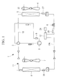
- Fig. 1 is a diagram showing a refrigeration cycle of an air conditioner according to this embodiment
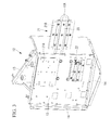
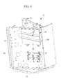
- Fig. 2 is a perspective view of a controller cooled by a refrigerant pipe that constitutes the refrigeration cycle.
- An air conditioner 1 is equipped with a compressor 2 that compresses refrigerant, a four-way switching valve 3 that switches the directions in which the refrigerant is circulated, an outdoor heat exchanger 5 that performs heat exchange between the refrigerant and outdoor air from an outdoor fan 4, an electronic expansion valve (expansion valve; EEV) 6 that causes the refrigerant to adiabatically expand, an indoor heat exchanger 8 that performs heat exchange between the refrigerant and indoor air from an indoor fan 7, and an accumulator 9, and is provided with a reversible refrigeration cycle 11 in which these components are connected by using refrigerant pipes 10.
- EEV electronic expansion valve
- the air conditioner 1 is provided with a controller 12 that controls the operation of the air conditioner 1 based on an operation instruction from a remote controller or the like.
- the controller 12 has a built-in inverter that controls the rotational speed of the compressor 2, has a function for switching the four-way switching valve 3 in accordance with the operation mode and, additionally, for controlling the rotational speed of the outdoor fan 4, the rotational speed of the indoor fan 7, the degree-of-opening of the electronic expansion valve 6, and so forth, and has a basic configuration that is no different from that of known controllers.
- a refrigerant pipe 10A is placed in contact with the controller 12 between the electronic expansion valve (EEV) 6 and the indoor heat exchanger 8 that constitute the refrigeration cycle 11; the controller 12 is cooled during cooling operation by means of low-pressure two-phase refrigerant that flows inside the refrigerant pipe 10A with the flow rate thereof reduced at the electronic expansion valve 6, and the controller 12 is cooled during heating operation by means of high-pressure liquid refrigerant that flows inside the refrigerant pipe 10A and that is condensed into liquid at the indoor heat exchanger 8.
- EEV electronic expansion valve
- the controller 12 is installed at an appropriate location on an outdoor unit of the air conditioner 1, the controller 12 is provided with a plurality of mounting surfaces 13, which are formed as vertical surfaces on which various control circuits, various control boards, electronic components, and so forth that constitute those circuits are provided, an installation flange 14, and so forth, as shown in Fig. 2 .
- cooling structures in the surroundings of heat-generating components, such as an active converter 15, a diode module 16, a power transistor 17, and so forth, for the inverter mounted in the controller 12 will mainly be described by using Figs. 2 to 5 .
- the active converter 15, the diode module 16, and the power transistor 17, described above, are provided on boards 18, 19, and 20, respectively, and these boards 18, 19, and 20 are securely installed on the mounting surfaces 13.
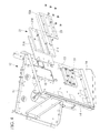
- heat-conducting blocks (aluminum blocks) 21 and 22 that constitute heat sinks are placed in close contact therewith.
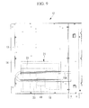
- the configuration of the heat-conducting block (aluminum block) 21 will be described below in detail based on Fig. 4 .
- Note that the configuration of the heat-conducting block 22 is the same as that of the heat-conducting block 21, and thus, a description thereof will be omitted.
- the heat-conducting block 21 is divided into two parts, namely, a plate-like first block 21A that is placed in contact with the boards 18 and 19 and a plate-like second block 21B that is placed in contact with the cooling refrigerant pipe 10A, and the first block 21A and the second block 21B can be coupled into a single unit via bolts or the like.
- the first block 21A which is one of the two divided parts of the heat-conducting block 21 that serves as a heat sink, is subassembled by being securely installed on the mounting surface 13 in a state in which the first block 21A is in close contact with the back surfaces of the boards 18 and 19, whereas the second block 21B is subassembled by being placed in contact with the refrigerant pipe 10A, and the first block 21A and the second block 21B can be coupled into a single unit on an assembly line.
- Two semicircular grooves 21C along which the refrigerant pipe 10A bent into a U-shape is placed are formed at a surface of the second block 21B, and the refrigerant pipe 10A is fitted into the semicircular grooves 21C, the outside thereof is held by using a pressing metal fitting 23 and secured by means of bolts, and thus, the subassembly is completed by installing the refrigerant pipe 10A in the second block 21B in close contact therewith. Note that the application of grease is not hindered when installing the refrigerant pipe 10A.
- the precision with which the refrigerant pipe 10A is installed in the heat-conducting block 21 is increased, and the heat conducting efficiency from the refrigerant pipe 10A to the heat-generating components on the boards 18 and 19, such as the active converter 15, the diode module 16, and so forth, is enhanced, thus increasing the cooling effect.
- condensation occurs on the surface of the refrigerant pipe 10A, drain liquid from the condensation drips onto the electronic components, such as the active converter 15, the diode module 16, the power transistor 17, and so forth, the boards 18, 19, and 20 on which those components are provided, or other electrical components or circuits, which causes malfunctioning and becomes a cause of damage to the electronic components; therefore, it is necessary to prevent the occurrence of condensation.
- the electronic components such as the active converter 15, the diode module 16, the power transistor 17, and so forth, the boards 18, 19, and 20 on which those components are provided, or other electrical components or circuits, which causes malfunctioning and becomes a cause of damage to the electronic components; therefore, it is necessary to prevent the occurrence of condensation.
- the controller 12 in order to prevent condensation at the refrigerant pipe 10A, the controller 12 is provided with a condensation-prevention control portion 24 (see Fig. 1 ).
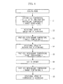
- This condensation-prevention control portion 24 has a function of preventing the occurrence of condensation based on a control flowchart shown in Fig. 6 .
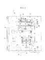
- the condensation-prevention control portion 24 sequentially performs condensation prevention control in the sequence described below when an outdoor air temperature detected by an outdoor-temperature sensor 25 is equal to or greater than a setting value A (for example, -5 °C) and when a post-EEV refrigerant temperature detected by a refrigerant-temperature sensor 26 provided in the refrigerant pipe 10A between the electronic expansion valve (EEV) 6 and the controller 12 is equal to or less than target temperatures 1 to 4 that are set in advance with respect to the outdoor air temperature detected by the outdoor-temperature sensor 25, as shown in Fig. 7 .
- a setting value A for example, -5 °C
- Step S1 when "outdoor air temperature > setting value A (-5 °C)" and “post-EEV refrigerant temperature ⁇ target temperature 1" are detected, and a risk of condensation occurring on the refrigerant pipe 10A is detected, rotational-speed control (which increases the rotational speed) of the indoor fan 7 is executed in Step S2. By doing so, the post-EEV refrigerant temperature is increased to a temperature equal to or greater than the target temperature 1, thus preventing condensation.
- Step S5 when "post-EEV refrigerant temperature ⁇ target temperature 3" is detected in Step S5, degree-of-opening control (which increases the degree-of-opening) of the electronic expansion valve (EEV) 6 is executed in Step S6, and, if this does not prevent a decrease in the post-EEV refrigerant temperature and "the post-EEV refrigerant temperature ⁇ target temperature 4" is detected in Step S7, rotational-speed control (which decreases the rotational speed) of the compressor 2 is executed in Step S8. By doing so, the refrigerant temperature is increased and the condensation is prevented.
- degree-of-opening control which increases the degree-of-opening of the electronic expansion valve (EEV) 6 is executed in Step S6
- Step S7 rotational-speed control (which decreases the rotational speed) of the compressor 2 is executed in Step S8.
- the condensation-prevention control portion 24 sequentially executes the condensation prevention control in which the rotational-speed control (which increases the rotational speed) of the indoor fan 7, the rotational-speed control (which decreases the rotational speed) of the outdoor fan 4, the degree-of-opening control (which increases the degree-of-opening) of the electronic expansion valve (EEV) 6, and the rotational-speed control (which decreases the rotational speed) of the compressor 2 are executed in this sequence, thus preventing the occurrence of condensation on the refrigerant pipe 10A.
- this sequence is set so as to be sequentially executed starting from a control having a low level of influence.
- the condensation-prevention control portion 24 sequentially executes the condensation prevention control in which the rotational-speed control (which increases the rotational speed) of the indoor fan 7, the rotational-speed control (which decreases the rotational speed) of the outdoor fan 4, the degree-of-opening control (which increases the degree-of-opening) of the electronic expansion valve (EEV) 6, and the rotational-speed control (which decreases the rotational speed) of the compressor 2 are executed in this sequence when the conditions for condensation to occur are detected; however, it is permissible to employ a configuration in which any one of the rotational-speed control (which increases the rotational speed) of the indoor fan 7, the rotational-speed control (which decreases the rotational speed) of the outdoor fan 4, the degree-of-opening control (which increases the degree-of-opening) of the electronic expansion valve (EEV) 6, and the rotational-speed control (which decreases the rotational speed) of the compressor 2 is executed when the conditions for condensation to occur are detected.
- the post-EEV refrigerant temperature is detected by providing the refrigerant-temperature sensor 26 in the refrigerant pipe 10A; however, it is permissible to employ a configuration in which this refrigerant-temperature sensor 26 is omitted and the condensation prevention control described above is performed by detecting, by using an existing temperature sensor, a temperature or the like that can be substituted for the post-EEV refrigerant temperature.
- a pseudo post-EEV refrigerant temperature may be calculated by using Expression (1) below based on detected values of the outdoor-heat-exchange temperature sensor 27 provided in the outdoor heat exchanger 5 and those of the indoor-heat-exchange temperature sensor 28 provided in the indoor heat exchanger 8, and the calculated pseudo post-EEV refrigerant temperature may be used in the condensation prevention control described above.
- pseudo post - EEV refrigerant temperature indoor - heat - exchange temperature + outdoor - heat - exchange temperature - indoor - heat - exchange temperature ⁇ C where C is a constant
- the refrigerant compressed at the compressor 2 is circulated, by means of the four-way switching valve 3, through the outdoor heat exchanger 5, the electronic expansion valve 6, the indoor heat exchanger 8, the four-way switching valve 3, the accumulator 9, and the compressor 2 in this order.
- the refrigerant that has been condensed into liquid by releasing heat to the outdoor air at the outdoor heat exchanger 5 is adiabatically expanded at the electronic expansion valve 6, is introduced into the indoor heat exchanger 8 in the form of low-pressure two-phase refrigerant, is evaporated at the indoor heat exchanger 8 by undergoing heat exchange with the indoor air blown thereinto by the indoor fan 7, and is, by cooling the indoor air, utilized in the cooling operation.
- the refrigerant compressed by the compressor 2 is circulated via the four-way switching valve 3 through the indoor heat exchanger 8, the electronic expansion valve 6, the outdoor heat exchanger 5, the four-way switching valve 3, the accumulator 9, and the compressor 2 in this order.
- the refrigerant is condensed into liquid by releasing heat to the indoor air at the indoor heat exchanger 8, and is utilized in the heating operation by heating the indoor air.
- the controller 12 is cooled by the refrigerant that flows inside the refrigerant pipe 10A that connects the electronic expansion valve 6 and the indoor heat exchanger 8.
- This refrigerant that flows inside the refrigerant pipe 10A during cooling operation is the low-pressure two-phase refrigerant that is adiabatically expanded at the electronic expansion valve 6 and, during heating operation, it is the high-pressure liquid refrigerant that is condensed into liquid at the indoor heat exchanger 8, which have sufficiently low temperature relative to the heat-generating components provided in the controller 12, such as the active converter 15, the diode module 16, the power transistor 17, and so forth, thus allowing these heat-generating components to be cooled.
- the temperature of the high-pressure liquid refrigerant does not allow frost formation even if the outdoor air temperature is low, and therefore, there is no risk of frost forming on the refrigerant pipe 10A that cools the controller 12.
- the temperature of the low-pressure refrigerant does not reach 0 °C or below under normal cooling conditions and the temperature of the refrigerant flowing into the controller 12 is assumed to normally reach 20 °C or greater due to pipe pressure loss or the like, and thus, there is no risk of condensation occurring; however, when the room temperature is low and the pressure is low, there could be a case in which condensation occurs.
- the condensation-prevention control portion 24 performs the condensation prevention control in which any one of the rotational-speed control (which increases the rotational speed) of the indoor fan 7, the rotational-speed control (which decreases the rotational speed) of the outdoor fan 4, the degree-of-opening control (which increases the degree-of-opening) of the electronic expansion valve (EEV) 6, and the rotational-speed control (which decreases the rotational speed) of the compressor 2 is performed or the condensation prevention control in which the above controls are sequentially performed in the above sequence, thus making it possible to prevent the occurrence of condensation.
- the refrigerant pipe 10A is placed via the heat-conducting blocks 21 and 22 that serve as heat sinks so as to be in close contact with the back surfaces of the boards 18, 19, and 20 on which the heat-generating components, such as the active converter 15, the diode module 16, the power transistor 17, and so forth, are provided.
- the heat-conducting block 21 (similar for the heat-conducting block 22) is divided into two parts, namely, the first block 21A that is placed in contact with the heat-generating components and the second block 21B that is placed in contact with the refrigerant pipe 10A, and the two divided parts, that is, the first block 21A and the second block 21B can be assembled into a single unit.
- the controller 12 although it is considerably difficult to place the refrigerant pipe 10A in close contact with the heat-conducting block 21 on the assembly line, which is placed in contact with the heat-generating components, it is possible to relatively easily place the refrigerant pipe 10A in close contact with the heat-conducting block 21 by placing the two divided parts, that is, the first block 21A and the second block 21B in close contact with the heat-generating components and the refrigerant pipe 10A, respectively, thus subassembling them in advance, and by assembling the first block 21A and the second block 21B into a single unit on the assembly line.
- the semicircular grooves 21C along which the refrigerant pipe 10A is placed are provided in the second block 21B. Because of this, by placing the refrigerant pipe 10A along the semicircular grooves 21C in the second block 21B and by securing them via the pressing metal fitting 23 or the like, it is possible to reliably place the refrigerant pipe 10A in close contact with the second block 21B, and, by doing so, it is possible to increase the heat conducting efficiency between the refrigerant pipe 10A and the heat-conducting block 21, and consequently, between the refrigerant pipe 10A and the controller 12, which makes it possible to further enhance the cooling performance for cooling the controller 12 and the heat-generating components thereof.
- the configuration in which the heat-conducting block 21 that serves as a heat sink is divided into two parts and in which the refrigerant pipe 10A is placed in contact with the controller 12 via the heat-conducting block 21 that is divided into two parts, as described above, is not limited to the system in which the refrigerant pipe 10A connecting the electronic expansion valve 6 and the indoor heat exchanger 8 is placed in contact with the controller 12, and this configuration can similarly be applied to a system in which a refrigerant pipe or the like connecting the electronic expansion valve 6 and the outdoor heat exchanger 5 is placed in contact with the controller 12 and in which the controller 12 is cooled during heating operation by means of the low-pressure two-phase refrigerant.
- This embodiment differs from the above-described first embodiment in that the refrigerant pipe 10A that is placed in contact with the controller 12 is placed at an angle. Because other aspects are the same as those of the first embodiment, descriptions thereof will be omitted.
- the refrigerant pipe 10A is placed in the heat-conducting block 21 at an angle by providing the semicircular grooves 21C, which are provided in the second block 21B of the heat-conducting block 21, at a certain angle ⁇ with respect to a horizontal direction.
- this embodiment is not limited to the system in which the refrigerant pipe 10A connecting between the electronic expansion valve 6 and the indoor heat exchanger 8 is placed in contact with the controller 12, and it can be similarly applied to a system in which a refrigerant pipe or the like connecting the electronic expansion valve 6 and the outdoor heat exchanger 5 is placed in contact with the controller 12 and in which the controller 12 is cooled during heating operation by means of the low-pressure two-phase refrigerant.
- This embodiment differs from the above-described first embodiment in that the placement of the heat-generating components provided in the controller 12 is changed. Because other aspects are the same as those of the first embodiment, descriptions thereof will be omitted.
- the boards 18, 19, and 20 on which the heat-generating components, such as the active converter 15, the diode module 16, the power transistor 17, and so forth, are provided are placed so as to be concentrated in a lower portion of the controller 12, and the refrigerant pipe 10A is placed in contact with these boards 18, 19, and 20 by interposing the heat-conducting block 21 having the above-described configuration therebetween.
- this embodiment is not limited to the system in which the refrigerant pipe 10A connecting the electronic expansion valve 6 and the indoor heat exchanger 8 is placed in contact with the controller 12, and it can similarly be applied to a system in which the refrigerant pipe or the like connecting the electronic expansion valve 6 and the outdoor heat exchanger 5 is placed in contact with the controller 12 and in which the controller 12 is cooled during heating operation by means of the low-pressure two-phase refrigerant.
- the heat-generating components provided in the controller 12 are placed so as to be concentrated in the lower portion of the controller 12 and the refrigerant pipe 10A is placed in contact with the lower portion, even if condensation or frost formation occurs on the surface of the refrigerant pipe 10A depending on the operating state, drain liquid from the condensation or frost does not drip onto other electronic components because no electronic components are placed in a lower portion below the heat-generating components. Therefore, it is possible to protect the controller by preventing the occurrence of malfunctioning, damage to the electronic components, or the like, due to the drain liquid dripping onto other electronic components provided in the controller.
- the present invention is not limited to the inventions according to the above-described embodiments, and appropriate modifications are possible within a range that does not depart from the scope thereof.
- the controller 12 has been described by using a unit having an open structure as an example, the structure of the controller 12 is not limited to those of the above-described embodiments, and it is needless to say that the present invention is similarly applicable to controllers having other structures such as a box structure or the like.
- the present invention may be an air conditioner which does not have a four-way switching valve 3 and used for a cooling-only air conditioner or a heating-only air conditioner.
Landscapes
- Engineering & Computer Science (AREA)
- Physics & Mathematics (AREA)
- Mechanical Engineering (AREA)
- Thermal Sciences (AREA)
- General Engineering & Computer Science (AREA)
- Air Conditioning Control Device (AREA)
- Other Air-Conditioning Systems (AREA)
Priority Applications (1)
| Application Number | Priority Date | Filing Date | Title |
|---|---|---|---|
| EP19191586.7A EP3587961A1 (fr) | 2013-11-26 | 2014-11-24 | Climatiseur |
Applications Claiming Priority (1)
| Application Number | Priority Date | Filing Date | Title |
|---|---|---|---|
| JP2013243961A JP6320731B2 (ja) | 2013-11-26 | 2013-11-26 | 空気調和機 |
Related Child Applications (1)
| Application Number | Title | Priority Date | Filing Date |
|---|---|---|---|
| EP19191586.7A Division EP3587961A1 (fr) | 2013-11-26 | 2014-11-24 | Climatiseur |
Publications (3)
| Publication Number | Publication Date |
|---|---|
| EP2876385A2 true EP2876385A2 (fr) | 2015-05-27 |
| EP2876385A3 EP2876385A3 (fr) | 2015-08-12 |
| EP2876385B1 EP2876385B1 (fr) | 2019-09-04 |
Family
ID=52003585
Family Applications (2)
| Application Number | Title | Priority Date | Filing Date |
|---|---|---|---|
| EP19191586.7A Withdrawn EP3587961A1 (fr) | 2013-11-26 | 2014-11-24 | Climatiseur |
| EP14194580.8A Active EP2876385B1 (fr) | 2013-11-26 | 2014-11-24 | Climatiseur |
Family Applications Before (1)
| Application Number | Title | Priority Date | Filing Date |
|---|---|---|---|
| EP19191586.7A Withdrawn EP3587961A1 (fr) | 2013-11-26 | 2014-11-24 | Climatiseur |
Country Status (3)
| Country | Link |
|---|---|
| EP (2) | EP3587961A1 (fr) |
| JP (1) | JP6320731B2 (fr) |
| ES (1) | ES2750251T3 (fr) |
Cited By (14)
| Publication number | Priority date | Publication date | Assignee | Title |
|---|---|---|---|---|
| CN105509251A (zh) * | 2015-12-31 | 2016-04-20 | 广东美的制冷设备有限公司 | 空调系统油堵的检测方法及检测装置、空调器 |
| CN107421015A (zh) * | 2017-07-07 | 2017-12-01 | Tcl空调器(中山)有限公司 | 空调器 |
| CN107421014A (zh) * | 2017-07-07 | 2017-12-01 | Tcl空调器(中山)有限公司 | 空调器散热装置、方法及空调器 |
| WO2018178485A1 (fr) * | 2017-03-29 | 2018-10-04 | Vicente Avila Chillida | Procédé de régulation de compresseurs inverseurs dans des installations de réfrigération |
| EP3361186A4 (fr) * | 2016-02-08 | 2018-10-24 | Mitsubishi Heavy Industries Thermal Systems, Ltd. | Dispositif à cycle de réfrigération |
| EP3421905A1 (fr) * | 2017-06-30 | 2019-01-02 | Mitsubishi Heavy Industries Thermal Systems, Ltd. | Tuyau composite, appareil de réfrigération et procédé de fabrication d'un tuyau composite |
| CN110440405A (zh) * | 2019-08-01 | 2019-11-12 | 珠海格力电器股份有限公司 | 一种有效防凝露的控制方法、装置及空调设备 |
| CN110454955A (zh) * | 2019-08-05 | 2019-11-15 | 广东美的制冷设备有限公司 | 空调器的控制方法、装置及空调器 |
| CN111271836A (zh) * | 2019-12-30 | 2020-06-12 | 宁波奥克斯电气股份有限公司 | 一种控制方法、装置、空调器及计算机可读存储介质 |
| CN111520873A (zh) * | 2020-05-25 | 2020-08-11 | 广东志高暖通设备股份有限公司 | 空调系统及其变频散热管的防凝露控制方法 |
| CN112032968A (zh) * | 2020-08-27 | 2020-12-04 | 海信(山东)空调有限公司 | 空调器及其控制方法和计算机可读存储介质 |
| CN113531829A (zh) * | 2021-07-09 | 2021-10-22 | 青岛海尔空调器有限总公司 | 用于空调控制的方法、装置及空调 |
| CN113865067A (zh) * | 2021-10-27 | 2021-12-31 | 美的集团武汉暖通设备有限公司 | 多联机空调及其控制方法、计算机可读存储介质 |
| CN115234963A (zh) * | 2022-06-28 | 2022-10-25 | 浙江中广电器集团股份有限公司 | 一种evi热泵三联供系统 |
Families Citing this family (4)
| Publication number | Priority date | Publication date | Assignee | Title |
|---|---|---|---|---|
| WO2017145276A1 (fr) * | 2016-02-24 | 2017-08-31 | 三菱電機株式会社 | Dispositif de climatisation |
| JP2017203575A (ja) * | 2016-05-10 | 2017-11-16 | 三菱重工サーマルシステムズ株式会社 | 電装部品冷却装置、これを備えた空調システムの室外機 |
| CN110186152A (zh) * | 2019-07-11 | 2019-08-30 | 芜湖美智空调设备有限公司 | 空调器及其控制方法、控制装置和计算机可读存储介质 |
| JP7553824B2 (ja) * | 2021-08-30 | 2024-09-19 | ダイキン工業株式会社 | 冷凍装置 |
Citations (1)
| Publication number | Priority date | Publication date | Assignee | Title |
|---|---|---|---|---|
| JP2008101862A (ja) | 2006-10-20 | 2008-05-01 | Daikin Ind Ltd | 電装品箱 |
Family Cites Families (10)
| Publication number | Priority date | Publication date | Assignee | Title |
|---|---|---|---|---|
| JP5446064B2 (ja) * | 2006-11-13 | 2014-03-19 | ダイキン工業株式会社 | 熱交換システム |
| US8950206B2 (en) * | 2007-10-05 | 2015-02-10 | Emerson Climate Technologies, Inc. | Compressor assembly having electronics cooling system and method |
| JP4488093B2 (ja) * | 2008-07-24 | 2010-06-23 | ダイキン工業株式会社 | 空気調和機 |
| JP2010175224A (ja) * | 2009-02-02 | 2010-08-12 | Daikin Ind Ltd | 空気調和装置 |
| US20120255318A1 (en) * | 2009-12-22 | 2012-10-11 | Naohiro Kido | Refrigeration apparatus |
| JPWO2011083756A1 (ja) * | 2010-01-05 | 2013-05-13 | ダイキン工業株式会社 | 冷凍装置 |
| CN103052852B (zh) * | 2011-06-29 | 2016-03-02 | 松下电器产业株式会社 | 冷却装置和具有该冷却装置的空气调节机 |
| DE102012102404A1 (de) * | 2012-03-21 | 2013-09-26 | Bitzer Kühlmaschinenbau Gmbh | Kälteanlage |
| US8950201B2 (en) * | 2012-03-30 | 2015-02-10 | Trane International Inc. | System and method for cooling power electronics using heat sinks |
| JP5408285B2 (ja) * | 2012-04-27 | 2014-02-05 | ダイキン工業株式会社 | 冷却器、電装品ユニット及び冷凍装置 |
-
2013
- 2013-11-26 JP JP2013243961A patent/JP6320731B2/ja active Active
-
2014
- 2014-11-24 EP EP19191586.7A patent/EP3587961A1/fr not_active Withdrawn
- 2014-11-24 ES ES14194580T patent/ES2750251T3/es active Active
- 2014-11-24 EP EP14194580.8A patent/EP2876385B1/fr active Active
Patent Citations (1)
| Publication number | Priority date | Publication date | Assignee | Title |
|---|---|---|---|---|
| JP2008101862A (ja) | 2006-10-20 | 2008-05-01 | Daikin Ind Ltd | 電装品箱 |
Cited By (21)
| Publication number | Priority date | Publication date | Assignee | Title |
|---|---|---|---|---|
| CN105509251B (zh) * | 2015-12-31 | 2018-11-20 | 广东美的制冷设备有限公司 | 空调系统油堵的检测方法及检测装置、空调器 |
| CN105509251A (zh) * | 2015-12-31 | 2016-04-20 | 广东美的制冷设备有限公司 | 空调系统油堵的检测方法及检测装置、空调器 |
| EP3361186A4 (fr) * | 2016-02-08 | 2018-10-24 | Mitsubishi Heavy Industries Thermal Systems, Ltd. | Dispositif à cycle de réfrigération |
| US10955178B2 (en) | 2017-03-29 | 2021-03-23 | Vicente AVILA CHILLIDA | Regulation method for inverter compressors in refrigeration facilities |
| WO2018178485A1 (fr) * | 2017-03-29 | 2018-10-04 | Vicente Avila Chillida | Procédé de régulation de compresseurs inverseurs dans des installations de réfrigération |
| EP3388760B1 (fr) | 2017-03-29 | 2019-08-28 | Nonwatio Technology Solutions, S.L. | Procédé de régulation pour compresseurs onduleurs dans des installations de réfrigération |
| EP3421905A1 (fr) * | 2017-06-30 | 2019-01-02 | Mitsubishi Heavy Industries Thermal Systems, Ltd. | Tuyau composite, appareil de réfrigération et procédé de fabrication d'un tuyau composite |
| CN107421015A (zh) * | 2017-07-07 | 2017-12-01 | Tcl空调器(中山)有限公司 | 空调器 |
| CN107421014A (zh) * | 2017-07-07 | 2017-12-01 | Tcl空调器(中山)有限公司 | 空调器散热装置、方法及空调器 |
| CN110440405A (zh) * | 2019-08-01 | 2019-11-12 | 珠海格力电器股份有限公司 | 一种有效防凝露的控制方法、装置及空调设备 |
| CN110454955A (zh) * | 2019-08-05 | 2019-11-15 | 广东美的制冷设备有限公司 | 空调器的控制方法、装置及空调器 |
| CN111271836A (zh) * | 2019-12-30 | 2020-06-12 | 宁波奥克斯电气股份有限公司 | 一种控制方法、装置、空调器及计算机可读存储介质 |
| CN111271836B (zh) * | 2019-12-30 | 2021-06-04 | 宁波奥克斯电气股份有限公司 | 一种控制方法、装置、空调器及计算机可读存储介质 |
| CN111520873A (zh) * | 2020-05-25 | 2020-08-11 | 广东志高暖通设备股份有限公司 | 空调系统及其变频散热管的防凝露控制方法 |
| CN111520873B (zh) * | 2020-05-25 | 2021-05-11 | 广东志高暖通设备股份有限公司 | 空调系统及其变频散热管的防凝露控制方法 |
| CN112032968A (zh) * | 2020-08-27 | 2020-12-04 | 海信(山东)空调有限公司 | 空调器及其控制方法和计算机可读存储介质 |
| CN113531829A (zh) * | 2021-07-09 | 2021-10-22 | 青岛海尔空调器有限总公司 | 用于空调控制的方法、装置及空调 |
| CN113865067A (zh) * | 2021-10-27 | 2021-12-31 | 美的集团武汉暖通设备有限公司 | 多联机空调及其控制方法、计算机可读存储介质 |
| CN113865067B (zh) * | 2021-10-27 | 2022-12-20 | 美的集团武汉暖通设备有限公司 | 多联机空调及其控制方法、计算机可读存储介质 |
| CN115234963A (zh) * | 2022-06-28 | 2022-10-25 | 浙江中广电器集团股份有限公司 | 一种evi热泵三联供系统 |
| CN115234963B (zh) * | 2022-06-28 | 2023-05-16 | 浙江中广电器集团股份有限公司 | 一种evi热泵三联供系统 |
Also Published As
| Publication number | Publication date |
|---|---|
| EP3587961A1 (fr) | 2020-01-01 |
| JP2015102295A (ja) | 2015-06-04 |
| JP6320731B2 (ja) | 2018-05-09 |
| EP2876385B1 (fr) | 2019-09-04 |
| EP2876385A3 (fr) | 2015-08-12 |
| ES2750251T3 (es) | 2020-03-25 |
Similar Documents
| Publication | Publication Date | Title |
|---|---|---|
| EP2876385B1 (fr) | Climatiseur | |
| EP3699514B1 (fr) | Systèmes et procédés pour commander un système de réfrigération | |
| EP3500805B1 (fr) | Systèmes et procédés de régulation de système frigorifique | |
| EP3929500B1 (fr) | Procédé et dispositif de commande de climatiseur et climatiseur | |
| US8578724B2 (en) | Heat pump and method of operation | |
| CN104819595A (zh) | 制冷系统、控制方法及装置和空调器 | |
| US20190301753A1 (en) | Air-conditioning apparatus | |
| CN110044032B (zh) | 空气调节装置的控制方法 | |
| US20200141609A1 (en) | Air conditioning system | |
| JP2014102050A (ja) | 冷凍装置 | |
| EP3273179B1 (fr) | Pompe à chaleur | |
| JP2010145054A (ja) | 冷凍装置 | |
| JP2013096642A (ja) | 冷却装置およびそれを備えた空気調和機 | |
| EP3440411B1 (fr) | Système hydronique refroidisseur redroidi à l'air | |
| WO2019194013A1 (fr) | Appareil de climatisation et appareil de commande de climatiseur | |
| CN109099523B (zh) | 散热器及空调系统 | |
| EP2863150A1 (fr) | Dispositif de réfrigération | |
| US11255582B2 (en) | HVAC systems and methods with multiple-path expansion device subsystems | |
| CN110044031B (zh) | 空气调节装置的控制方法及电控盒组件、空气调节装置 | |
| JP2010147334A (ja) | 冷凍装置 | |
| CN109154516B (zh) | 液体检测系统 | |
| JP2017227413A (ja) | 空気調和機 | |
| JP2010025373A (ja) | 冷凍装置 | |
| KR100676143B1 (ko) | 공기조화기 | |
| KR20190061257A (ko) | 히트펌프용 압력/온도 센서를 포함하는 조립체 |
Legal Events
| Date | Code | Title | Description |
|---|---|---|---|
| PUAI | Public reference made under article 153(3) epc to a published international application that has entered the european phase |
Free format text: ORIGINAL CODE: 0009012 |
|
| 17P | Request for examination filed |
Effective date: 20141124 |
|
| AK | Designated contracting states |
Kind code of ref document: A2 Designated state(s): AL AT BE BG CH CY CZ DE DK EE ES FI FR GB GR HR HU IE IS IT LI LT LU LV MC MK MT NL NO PL PT RO RS SE SI SK SM TR |
|
| AX | Request for extension of the european patent |
Extension state: BA ME |
|
| PUAL | Search report despatched |
Free format text: ORIGINAL CODE: 0009013 |
|
| AK | Designated contracting states |
Kind code of ref document: A3 Designated state(s): AL AT BE BG CH CY CZ DE DK EE ES FI FR GB GR HR HU IE IS IT LI LT LU LV MC MK MT NL NO PL PT RO RS SE SI SK SM TR |
|
| AX | Request for extension of the european patent |
Extension state: BA ME |
|
| RIC1 | Information provided on ipc code assigned before grant |
Ipc: F25B 31/00 20060101AFI20150707BHEP Ipc: F25B 13/00 20060101ALN20150707BHEP Ipc: F25B 49/02 20060101ALI20150707BHEP |
|
| R17P | Request for examination filed (corrected) |
Effective date: 20160202 |
|
| RBV | Designated contracting states (corrected) |
Designated state(s): AL AT BE BG CH CY CZ DE DK EE ES FI FR GB GR HR HU IE IS IT LI LT LU LV MC MK MT NL NO PL PT RO RS SE SI SK SM TR |
|
| RAP1 | Party data changed (applicant data changed or rights of an application transferred) |
Owner name: MITSUBISHI HEAVY INDUSTRIES THERMAL SYSTEMS, LTD. |
|
| RIC1 | Information provided on ipc code assigned before grant |
Ipc: F25B 31/00 20060101AFI20190204BHEP Ipc: F25B 49/02 20060101ALI20190204BHEP Ipc: F25B 13/00 20060101ALN20190204BHEP |
|
| GRAP | Despatch of communication of intention to grant a patent |
Free format text: ORIGINAL CODE: EPIDOSNIGR1 |
|
| STAA | Information on the status of an ep patent application or granted ep patent |
Free format text: STATUS: GRANT OF PATENT IS INTENDED |
|
| INTG | Intention to grant announced |
Effective date: 20190322 |
|
| GRAS | Grant fee paid |
Free format text: ORIGINAL CODE: EPIDOSNIGR3 |
|
| GRAA | (expected) grant |
Free format text: ORIGINAL CODE: 0009210 |
|
| STAA | Information on the status of an ep patent application or granted ep patent |
Free format text: STATUS: THE PATENT HAS BEEN GRANTED |
|
| AK | Designated contracting states |
Kind code of ref document: B1 Designated state(s): AL AT BE BG CH CY CZ DE DK EE ES FI FR GB GR HR HU IE IS IT LI LT LU LV MC MK MT NL NO PL PT RO RS SE SI SK SM TR |
|
| REG | Reference to a national code |
Ref country code: GB Ref legal event code: FG4D |
|
| REG | Reference to a national code |
Ref country code: CH Ref legal event code: EP |
|
| REG | Reference to a national code |
Ref country code: AT Ref legal event code: REF Ref document number: 1175929 Country of ref document: AT Kind code of ref document: T Effective date: 20190915 |
|
| REG | Reference to a national code |
Ref country code: DE Ref legal event code: R096 Ref document number: 602014052880 Country of ref document: DE |
|
| REG | Reference to a national code |
Ref country code: IE Ref legal event code: FG4D |
|
| REG | Reference to a national code |
Ref country code: NL Ref legal event code: MP Effective date: 20190904 |
|
| REG | Reference to a national code |
Ref country code: LT Ref legal event code: MG4D |
|
| PG25 | Lapsed in a contracting state [announced via postgrant information from national office to epo] |
Ref country code: SE Free format text: LAPSE BECAUSE OF FAILURE TO SUBMIT A TRANSLATION OF THE DESCRIPTION OR TO PAY THE FEE WITHIN THE PRESCRIBED TIME-LIMIT Effective date: 20190904 Ref country code: NO Free format text: LAPSE BECAUSE OF FAILURE TO SUBMIT A TRANSLATION OF THE DESCRIPTION OR TO PAY THE FEE WITHIN THE PRESCRIBED TIME-LIMIT Effective date: 20191204 Ref country code: FI Free format text: LAPSE BECAUSE OF FAILURE TO SUBMIT A TRANSLATION OF THE DESCRIPTION OR TO PAY THE FEE WITHIN THE PRESCRIBED TIME-LIMIT Effective date: 20190904 Ref country code: HR Free format text: LAPSE BECAUSE OF FAILURE TO SUBMIT A TRANSLATION OF THE DESCRIPTION OR TO PAY THE FEE WITHIN THE PRESCRIBED TIME-LIMIT Effective date: 20190904 Ref country code: BG Free format text: LAPSE BECAUSE OF FAILURE TO SUBMIT A TRANSLATION OF THE DESCRIPTION OR TO PAY THE FEE WITHIN THE PRESCRIBED TIME-LIMIT Effective date: 20191204 Ref country code: LT Free format text: LAPSE BECAUSE OF FAILURE TO SUBMIT A TRANSLATION OF THE DESCRIPTION OR TO PAY THE FEE WITHIN THE PRESCRIBED TIME-LIMIT Effective date: 20190904 |
|
| PG25 | Lapsed in a contracting state [announced via postgrant information from national office to epo] |
Ref country code: GR Free format text: LAPSE BECAUSE OF FAILURE TO SUBMIT A TRANSLATION OF THE DESCRIPTION OR TO PAY THE FEE WITHIN THE PRESCRIBED TIME-LIMIT Effective date: 20191205 Ref country code: AL Free format text: LAPSE BECAUSE OF FAILURE TO SUBMIT A TRANSLATION OF THE DESCRIPTION OR TO PAY THE FEE WITHIN THE PRESCRIBED TIME-LIMIT Effective date: 20190904 Ref country code: LV Free format text: LAPSE BECAUSE OF FAILURE TO SUBMIT A TRANSLATION OF THE DESCRIPTION OR TO PAY THE FEE WITHIN THE PRESCRIBED TIME-LIMIT Effective date: 20190904 Ref country code: RS Free format text: LAPSE BECAUSE OF FAILURE TO SUBMIT A TRANSLATION OF THE DESCRIPTION OR TO PAY THE FEE WITHIN THE PRESCRIBED TIME-LIMIT Effective date: 20190904 |
|
| REG | Reference to a national code |
Ref country code: AT Ref legal event code: MK05 Ref document number: 1175929 Country of ref document: AT Kind code of ref document: T Effective date: 20190904 |
|
| REG | Reference to a national code |
Ref country code: ES Ref legal event code: FG2A Ref document number: 2750251 Country of ref document: ES Kind code of ref document: T3 Effective date: 20200325 |
|
| PG25 | Lapsed in a contracting state [announced via postgrant information from national office to epo] |
Ref country code: PT Free format text: LAPSE BECAUSE OF FAILURE TO SUBMIT A TRANSLATION OF THE DESCRIPTION OR TO PAY THE FEE WITHIN THE PRESCRIBED TIME-LIMIT Effective date: 20200106 Ref country code: RO Free format text: LAPSE BECAUSE OF FAILURE TO SUBMIT A TRANSLATION OF THE DESCRIPTION OR TO PAY THE FEE WITHIN THE PRESCRIBED TIME-LIMIT Effective date: 20190904 Ref country code: PL Free format text: LAPSE BECAUSE OF FAILURE TO SUBMIT A TRANSLATION OF THE DESCRIPTION OR TO PAY THE FEE WITHIN THE PRESCRIBED TIME-LIMIT Effective date: 20190904 Ref country code: NL Free format text: LAPSE BECAUSE OF FAILURE TO SUBMIT A TRANSLATION OF THE DESCRIPTION OR TO PAY THE FEE WITHIN THE PRESCRIBED TIME-LIMIT Effective date: 20190904 Ref country code: EE Free format text: LAPSE BECAUSE OF FAILURE TO SUBMIT A TRANSLATION OF THE DESCRIPTION OR TO PAY THE FEE WITHIN THE PRESCRIBED TIME-LIMIT Effective date: 20190904 Ref country code: AT Free format text: LAPSE BECAUSE OF FAILURE TO SUBMIT A TRANSLATION OF THE DESCRIPTION OR TO PAY THE FEE WITHIN THE PRESCRIBED TIME-LIMIT Effective date: 20190904 |
|
| PG25 | Lapsed in a contracting state [announced via postgrant information from national office to epo] |
Ref country code: IS Free format text: LAPSE BECAUSE OF FAILURE TO SUBMIT A TRANSLATION OF THE DESCRIPTION OR TO PAY THE FEE WITHIN THE PRESCRIBED TIME-LIMIT Effective date: 20200224 Ref country code: CZ Free format text: LAPSE BECAUSE OF FAILURE TO SUBMIT A TRANSLATION OF THE DESCRIPTION OR TO PAY THE FEE WITHIN THE PRESCRIBED TIME-LIMIT Effective date: 20190904 Ref country code: SM Free format text: LAPSE BECAUSE OF FAILURE TO SUBMIT A TRANSLATION OF THE DESCRIPTION OR TO PAY THE FEE WITHIN THE PRESCRIBED TIME-LIMIT Effective date: 20190904 Ref country code: SK Free format text: LAPSE BECAUSE OF FAILURE TO SUBMIT A TRANSLATION OF THE DESCRIPTION OR TO PAY THE FEE WITHIN THE PRESCRIBED TIME-LIMIT Effective date: 20190904 |
|
| REG | Reference to a national code |
Ref country code: DE Ref legal event code: R119 Ref document number: 602014052880 Country of ref document: DE |
|
| REG | Reference to a national code |
Ref country code: CH Ref legal event code: PL |
|
| PLBE | No opposition filed within time limit |
Free format text: ORIGINAL CODE: 0009261 |
|
| STAA | Information on the status of an ep patent application or granted ep patent |
Free format text: STATUS: NO OPPOSITION FILED WITHIN TIME LIMIT |
|
| PG2D | Information on lapse in contracting state deleted |
Ref country code: IS |
|
| PG25 | Lapsed in a contracting state [announced via postgrant information from national office to epo] |
Ref country code: LU Free format text: LAPSE BECAUSE OF NON-PAYMENT OF DUE FEES Effective date: 20191124 Ref country code: LI Free format text: LAPSE BECAUSE OF NON-PAYMENT OF DUE FEES Effective date: 20191130 Ref country code: CH Free format text: LAPSE BECAUSE OF NON-PAYMENT OF DUE FEES Effective date: 20191130 Ref country code: DK Free format text: LAPSE BECAUSE OF FAILURE TO SUBMIT A TRANSLATION OF THE DESCRIPTION OR TO PAY THE FEE WITHIN THE PRESCRIBED TIME-LIMIT Effective date: 20190904 Ref country code: MC Free format text: LAPSE BECAUSE OF FAILURE TO SUBMIT A TRANSLATION OF THE DESCRIPTION OR TO PAY THE FEE WITHIN THE PRESCRIBED TIME-LIMIT Effective date: 20190904 Ref country code: IS Free format text: LAPSE BECAUSE OF FAILURE TO SUBMIT A TRANSLATION OF THE DESCRIPTION OR TO PAY THE FEE WITHIN THE PRESCRIBED TIME-LIMIT Effective date: 20200105 |
|
| 26N | No opposition filed |
Effective date: 20200605 |
|
| REG | Reference to a national code |
Ref country code: BE Ref legal event code: MM Effective date: 20191130 |
|
| PG25 | Lapsed in a contracting state [announced via postgrant information from national office to epo] |
Ref country code: SI Free format text: LAPSE BECAUSE OF FAILURE TO SUBMIT A TRANSLATION OF THE DESCRIPTION OR TO PAY THE FEE WITHIN THE PRESCRIBED TIME-LIMIT Effective date: 20190904 |
|
| GBPC | Gb: european patent ceased through non-payment of renewal fee |
Effective date: 20191204 |
|
| PG25 | Lapsed in a contracting state [announced via postgrant information from national office to epo] |
Ref country code: GB Free format text: LAPSE BECAUSE OF NON-PAYMENT OF DUE FEES Effective date: 20191204 Ref country code: IE Free format text: LAPSE BECAUSE OF NON-PAYMENT OF DUE FEES Effective date: 20191124 Ref country code: DE Free format text: LAPSE BECAUSE OF NON-PAYMENT OF DUE FEES Effective date: 20200603 |
|
| PG25 | Lapsed in a contracting state [announced via postgrant information from national office to epo] |
Ref country code: BE Free format text: LAPSE BECAUSE OF NON-PAYMENT OF DUE FEES Effective date: 20191130 |
|
| PG25 | Lapsed in a contracting state [announced via postgrant information from national office to epo] |
Ref country code: CY Free format text: LAPSE BECAUSE OF FAILURE TO SUBMIT A TRANSLATION OF THE DESCRIPTION OR TO PAY THE FEE WITHIN THE PRESCRIBED TIME-LIMIT Effective date: 20190904 |
|
| PG25 | Lapsed in a contracting state [announced via postgrant information from national office to epo] |
Ref country code: MT Free format text: LAPSE BECAUSE OF FAILURE TO SUBMIT A TRANSLATION OF THE DESCRIPTION OR TO PAY THE FEE WITHIN THE PRESCRIBED TIME-LIMIT Effective date: 20190904 Ref country code: HU Free format text: LAPSE BECAUSE OF FAILURE TO SUBMIT A TRANSLATION OF THE DESCRIPTION OR TO PAY THE FEE WITHIN THE PRESCRIBED TIME-LIMIT; INVALID AB INITIO Effective date: 20141124 |
|
| PG25 | Lapsed in a contracting state [announced via postgrant information from national office to epo] |
Ref country code: TR Free format text: LAPSE BECAUSE OF FAILURE TO SUBMIT A TRANSLATION OF THE DESCRIPTION OR TO PAY THE FEE WITHIN THE PRESCRIBED TIME-LIMIT Effective date: 20190904 |
|
| PG25 | Lapsed in a contracting state [announced via postgrant information from national office to epo] |
Ref country code: MK Free format text: LAPSE BECAUSE OF FAILURE TO SUBMIT A TRANSLATION OF THE DESCRIPTION OR TO PAY THE FEE WITHIN THE PRESCRIBED TIME-LIMIT Effective date: 20190904 |
|
| PGFP | Annual fee paid to national office [announced via postgrant information from national office to epo] |
Ref country code: FR Payment date: 20230929 Year of fee payment: 10 |
|
| PGFP | Annual fee paid to national office [announced via postgrant information from national office to epo] |
Ref country code: ES Payment date: 20231201 Year of fee payment: 10 |
|
| PGFP | Annual fee paid to national office [announced via postgrant information from national office to epo] |
Ref country code: IT Payment date: 20231010 Year of fee payment: 10 |