EP2875993A2 - Verfahrbare Vorrichtung zum Bewegen von Transportbehältern - Google Patents
Verfahrbare Vorrichtung zum Bewegen von Transportbehältern Download PDFInfo
- Publication number
- EP2875993A2 EP2875993A2 EP14003295.4A EP14003295A EP2875993A2 EP 2875993 A2 EP2875993 A2 EP 2875993A2 EP 14003295 A EP14003295 A EP 14003295A EP 2875993 A2 EP2875993 A2 EP 2875993A2
- Authority
- EP
- European Patent Office
- Prior art keywords
- receiving
- hook
- axis
- rotation
- arm
- Prior art date
- Legal status (The legal status is an assumption and is not a legal conclusion. Google has not performed a legal analysis and makes no representation as to the accuracy of the status listed.)
- Granted
Links
Images

Classifications
-
- B—PERFORMING OPERATIONS; TRANSPORTING
- B60—VEHICLES IN GENERAL
- B60P—VEHICLES ADAPTED FOR LOAD TRANSPORTATION OR TO TRANSPORT, TO CARRY, OR TO COMPRISE SPECIAL LOADS OR OBJECTS
- B60P1/00—Vehicles predominantly for transporting loads and modified to facilitate loading, consolidating the load, or unloading
- B60P1/64—Vehicles predominantly for transporting loads and modified to facilitate loading, consolidating the load, or unloading the load supporting or containing element being readily removable
- B60P1/6418—Vehicles predominantly for transporting loads and modified to facilitate loading, consolidating the load, or unloading the load supporting or containing element being readily removable the load-transporting element being a container or similar
- B60P1/6463—Vehicles predominantly for transporting loads and modified to facilitate loading, consolidating the load, or unloading the load supporting or containing element being readily removable the load-transporting element being a container or similar fitted with articulated beams for longitudinal displacement of the container
Definitions
- the invention relates to a movable device for moving end provided with a coupling means transport containers, such as those from the DE 20 2007 017 616 U1 is known.
- the known device is provided with a chassis and a pivotally mounted on this hook, which can be brought from a lowered rest position into a raised or swiveled receiving position, in which it can be brought into engagement with a coupling device of a transport container to be moved.
- the object of the present invention is to ensure a safe and wear-free and damage-free engagement between the hook and coupling device even at larger angles between a longitudinal axis of the movable device and a longitudinal axis of a moving container to be moved.
- a movable device for moving end provided with a coupling transport containers, with a Chassis on which at least one wheel drivable by means of a drive and at least one wheel controllable by a steering device are arranged, and a hook device held on the chassis, pivotable about a horizontal pivot axis between a rest position and a receiving position
- the device is characterized according to the invention, in that the hook device has a receiving arm which can be pivoted about the pivot axis and has a receiving hook which is rotatably held about a rotational axis, wherein the rotational axis is arranged perpendicular to and at a distance from the pivot axis.
- This arrangement enables an angle compensation between the device and the transport container by the receiving hook can rotate relative to the receiving arm and at least partially align with the transport container.
- the axis of rotation is arranged stationary with respect to the receiving arm, wherein it pivots with a pivoting movement of the receiving arm with this.
- the receiving arm of two parallel arranged and pivotally hinged to the chassis parallellogrammlenkurer and hinged to the Parallellogrammlenkern support body is formed, wherein the rotation axis is arranged on the support body.
- the axis of rotation remains at a pivotal movement of Parallellogrammlenker in a predetermined orientation.
- the axis of rotation in the receiving position is arranged vertically or at an angle of up to 5 °, 10 °, 20 °, 30 ° or 45 ° to the vertical.
- the pickup arm is designed as a pair of parallelogram links, it can be provided that the axis of rotation is always arranged vertically.
- the hook device is arranged on or adjacent to a horizontal platform of the device for pulling a transport container onto the platform.
- a compressor roller is articulated to the device and can be brought into an open transport container and in this back and forth.
- the hook device can be arranged in a front region and / or in a rear region of the device. It can be provided that a driver's cab is arranged on the chassis, from which the hook device arranged in the front region of the device is visible, at least in the receiving position, by a seated driver, at least their receiving hooks.
- the receiving hook has a neutral position with respect to a rotation about the axis of rotation in which it or its longitudinal center plane is aligned with the receiving arm or with the longitudinal axis of the device, wherein a particular spring-actuated return means between the receiving arm and the receiving hook is arranged , Which applies a restoring force in the direction of the neutral position on the receiving hook during a rotation of the receiving hook.
- the invention further provides preferably that the receiving hook has a hook body and a hook arm connected thereto and a hook mouth with a receiving opening forming, the receiving opening may point in the receiving position of the hook device in a direction away from the chassis direction.
- the receiving hook may have a load receiving area, which is formed by an upper side of the hook arm and possibly additionally by an inner surface of the hook body.
- the axis of rotation may extend through the load receiving area or at a distance from the load receiving area at a point between it and the pivot axis.
- a first embodiment is in Fig. 1 and 2 shown.
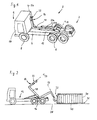
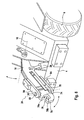
- the device is a so-called roll-off dump truck 2 with a chassis 4 with driven rear wheels 6 in a rear area 7 and steerable front wheels 8 in a front area 9, a drive (not shown), a cab 10 and a substantially flat rear load-bearing area or platform 12
- a pivotable hook device 14 is mounted, which has an L-shaped, about a horizontal pivot axis 16 pivotable receiving arm 18, the pivotal movement of two hydraulic piston / cylinder units 20a, b is controllable on the one hand on the chassis 4 and on the other are hinged to the receiving arm 18.
- the receiving arm 18 carries at a free end a receiving hook 22 which is rotatable about an axis of rotation 24 relative to the receiving arm 18.
- the axis of rotation 23 extends perpendicular to and at a distance from the pivot axis 16 about which the receiving arm 18 is articulated to the chassis 4.
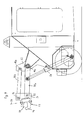
- FIG. 1 shows a retracted rest position of the hook device 14, in which a part of the receiving arm 18 rests on the platform 12, shows Fig. 2 two different positions of the hook device 14.
- an intermediate position is shown, in which the receiving arm 18 by about 45 ° relative to the rest position after Fig. 1 is pivoted up, and further an extended receiving position, in which the receiving arm 18 is pivoted relative to the rest position by about 150 ° and the receiving hook 22 is suitably positioned for receiving a transport container.
- the axis of rotation 24 of the receiving hook 22 is approximately vertical and is inclined in the illustrated embodiment by approximately 25 ° to the vertical.
- a transport container 30 to be moved is shown, which is provided at one end with a coupling device 32, with which the receiving hook 22 can be brought into engagement.
- the coupling device 32 can in a known manner by a Rundbaum of a substantially semi-circular curved Be formed material round cross-section, which is fixedly connected to an end wall of the transport container 30.
- the transport container 20 has on its side opposite the coupling device 32 side rollers 36, with which it can roll on a substrate 38 when it is unilaterally raised on the side of the coupling device 32.
- the transport container 30 can be received in a manner known per se by the roll-off dump truck 2, in which the receiving hook 22 is brought into engagement with the coupling device 32 or eyelet, and the transport container 30 is then moved by pivoting the pick-up arm 18 over the in Fig. 2 shown intermediate position to the in Fig. 1 shown rest position is pulled onto the platform 12. Since in this process, in particular in the course of the engagement of the receiving hook 22 with the coupling device 32, it often happens that the roll-off dump truck 2 is not aligned with the transport container 30, wherein a longitudinal axis 2a of the device is an angle of up to 10 °, 20 °, 30 °, 45 ° or even more with a longitudinal axis 30a of the transport container 30 includes (see also Fig. 5 ), an unfavorable engagement of the receiving hook 22 in the coupling device 32 or jamming may result. Wear and damage can be the result.
- the receiving hook 22 is rotatable about the axis of rotation 24 relative to the receiving arm 18, so that a compensation of a possible angular position between the Abrollkipperhus 2 and the transport container 30 can be made. Because the receiving hook 22 can rotate, it can assume an angular position, in which it cooperates favorably with the coupling device 32, so that damage or excessive wear is ruled out.
- Fig. 3 to 8 explain a second and third embodiment.
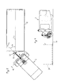
- the movable device is in these cases not designed as a dump truck, but as a vehicle for moving transport containers, preferably provided with a device for Compacting of garbage, as long as the transport containers are open-top receptacles for waste or garbage (second embodiment according to US Pat Fig. 3 ).
- a pivotable hook device 14 is arranged, with a about a horizontal pivot axis 16 pivotable receiving arm 18 which carries a receiving hook 22.
- the pivot axis 16 is held on the chassis 4.
- Fig. 3 shows a lowered or retracted rest position of the hook device 14 between the pickup arm 18 and the chassis 4 acting a piston / cylinder unit 20 is arranged, with the receiving arm 18 in a in Fig. 7 shown raised or extended receiving position can be brought.
- Both the receiving arm 18 and the piston / cylinder unit 20 may be detachably connected to the chassis 4, for example by means of bolts.
- Fig. 3 further shows that on the chassis 4, a compressor roller 50 is articulated, which can be moved into the transport container 30.
- the compressor roller 50 is drivable about a horizontal axis 52 and has on its outer cylindrical surface driver or crushing projections 54.
- a first, hinged to the chassis 4 articulated arm 56 and a hinged thereto second articulated arm 58 which carries the compressor roller 50 at its free end, it can be reciprocated in the transport container 30, whereby the waste contained therein compressed and is crushed.
- FIG 3 shows two positions of the compressor roller 50, a rest position in which the hinge arms 56, 58 and the compressor roller 50 are located substantially above the front portion and the hook means 14 of the device, and a working position in which the compressor roller 50 is in the transport container 30 and the hinge arms 50, 58 occupy a substantially extended position.
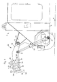
- Fig. 4 shows as a third embodiment one of Fig. 3 corresponding device, only without compressor roller 50, wherein a transport container 30 is at such a distance in front of the device, that when the receiving arm 18 is pivoted from the illustrated rest position to the receiving position, located at the end of the receiving arm 18 receiving hooks 22 with the Coupling device 32 can be brought in the form of an eyelet into engagement.
- Fig. 5 shows such an intervention situation in a plan view, with the special feature that a longitudinal axis 2a of the device forms a considerable angle 26 with a longitudinal axis 30a of the transport container 30, so that engagement of a rigidly connected to the receiving arm 18 receiving hook 22 in the coupling device or eye 32 would be difficult.
- the receiving hook 22 is rotatably held about the rotation axis 24 on the receiving arm 18, similar to already in connection with Fig. 1 and 2 has been explained.
- Fig. 6 shows an enlarged sectional view of the engagement portion between the receiving hook 22 and eyelet 32 according to Fig. 5 , wherein a rotation of the receiving hook 22 with longitudinal center plane 22a about the rotation axis 24, which is substantially vertical in this case, relative to the receiving arm 18 and the longitudinal axis 2a by an angle 60 with respect to a non-rotated, with the receiving arm 18 and the longitudinal axis 2a aligned starting position is clearly visible.
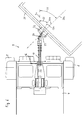
- FIG. 7 and 8th explain the structure of the pivotable hook device 14 in more detail.
- a mounting lug 62 on the chassis 4 of the device 2 carries the horizontal pivot axis 16 about which the receiving arm 18 is pivotally articulated.
- One or, if necessary, two piston / cylinder unit (s) 20 extends between a first pivot point 64 on the chassis 4 and a second pivot point 66 on the receiving arm 18, which is located between the pivot axis 16 and the receiving hook 22.
- the pivot axis 16 opposite end of the receiving arm 18 of the receiving hook 22 is rotatably supported about a rotation axis 24, wherein the axis of rotation 24 is in a vertical plane or perpendicular to the horizontal pivot axis 16.
- Fig. 7 and 8th show a raised or extended operating state of the hook device 14, in which the rotation axis 24 is oriented substantially vertically and preferably forms an angle of less than 45 °, 30 ° 20 ° or 10 ° to the vertical.
- a return means is preferably provided which moves the receiving hook 22 in the unloaded state in the neutral position.
- Fig. 6 and 7 show a variant of such a return means in the form of two on both sides of the receiving arm 18 mounted spring tongues 70 which abut against the receiving hooks 22 from both sides and exert an elastic restoring force as soon as the receiving hook is rotated from the neutral position.
- the receiving hook 22 has a hook body 74, from which a hook arm 76 goes off.
- a load receiving area 78 is formed by an at least partially or selectively horizontal surface on the upper side of the hook arm 76.
- the load receiving area 78 may further comprise laterally adjacent surfaces of the hook arm 76 and the hook body 74 and may be concave or saddle-shaped as viewed generally vertically upward.
- two bearing pins 80 are formed, which are aligned with the axis of rotation 24 and engage in each case a bearing opening 82 of a bearing arm 84, wherein the bearing arms 84 are in turn held on the receiving arm 18.
- the bearing pins 80 define with the bearing openings 82, the rotation axis 84 which is pivoted together with the receiving arm 18.
- FIG. 9 illustrated variant of the receiving arm 18 by two Parallellogrammlenker 90a, b are formed.
- a first, lower parallelogram link 90a is articulated on the one hand via a horizontal pivot axis 16a on the chassis 4 and hinged at the opposite end via a horizontal pivot axis 92 with a support body 94.
- a second Parallellogrammlenker 90b is hinged to a horizontal pivot axis 16b on the chassis 4 and connected at its other end via a horizontal pivot axis 96 with the support body 94 articulated.
- An effective length of the first parallelogram link 90a corresponding to a distance between the pivot axis 16a and the pivot axis 92 is preferably equal to an effective length of the second parallel loop link 90b corresponding to a distance between the pivot axis 16b and the pivot axis 96.
- a distance between the pivot axes 16a , B on the one hand is preferably equal to a distance between the pivot axes 92, 96 on the support body 94, and a plane containing the pivot axes 16a, b on the chassis is preferably parallel to a plane containing the pivot axes 92, 96 on the support body.
- the Fig. 9 is shown, not or only slightly changed and preferably always vertical.
- the load receiving area 78 of the receiving hook 22 may extend between a first end portion 78a facing the receiving arm 18 and a second end portion 78b facing away from the receiving arm 18, the second end portion 78b being spaced from the axis of rotation 24 and the first End portion 78a may be disposed on the rotation axis 24 or between the rotation axis 24 and the pivot axis 16.
- Such an arrangement has the purpose that in a pulling operation of a transport container 30, in which the device 2 backward, with the rear portion 7 ahead, or according to Fig.
- the force acting on the receiving hooks 22 pulling force is directed away from the chassis and thus tends to align the hook in the direction of its neutral position, while in a shift operation in which the Device 2 forward, with its front portion 9 ahead or in Fig. 7 moved to the left, acting on the receiving hook 22 in the direction of the chassis compressive force due to their introduction either on the axis of rotation 24 or at a lying between the axis of rotation 24 and pivot axis 16 point also tends to align the receiving hooks 22 in its normal position.
- the axis of rotation 24 can also extend substantially centrally through the load receiving area 78, between the first end area 78a and the second end area 78b.
Landscapes
- Engineering & Computer Science (AREA)
- Transportation (AREA)
- Mechanical Engineering (AREA)
- Refuse-Collection Vehicles (AREA)
- Intermediate Stations On Conveyors (AREA)
- Chain Conveyers (AREA)
- Handcart (AREA)
- Loading Or Unloading Of Vehicles (AREA)
Abstract
Description
- Die Erfindung betrifft eine verfahrbare Vorrichtung zum Bewegen von endseitig mit einer Kopplungseinrichtung versehenen Transportbehältern, wie sie etwa aus der
DE 20 2007 017 616 U1 bekannt ist. Die bekannte Vorrichtung ist mit einem Fahrgestell und einem an diesem schwenkbar gelagerten Haken versehen, der von einer abgesenkten Ruhestellung in eine angehobene bzw. hochgeschwenkte Aufnahmestellung bringbar ist, in der er mit einer Kopplungseinrichtung eines zu bewegenden Transportbehälters in Eingriff bringbar ist. - Obwohl sich die bekannte Vorrichtung in der Praxis bewährt hat, kann der Eingriff des Hakens in die Kopplungseinrichtung des Transportbehälters bei größeren Winkeln zwischen einer Längsachse der Vorrichtung und einer Längsachse des Transportbehälters (bei enger Kurvenfahrt bzw. Lenkeinschlag der Vorrichtung) problematisch sein und zu einem Verklemmen, starkem Verschleiß oder sogar zu Beschädigungen an Haken oder Kopplungseinrichtung führen.
- Die Aufgabe der vorliegenden Erfindung besteht darin, auch bei größeren Winkeln zwischen einer Längsachse der verfahrbaren Vorrichtung und einer Längsachse eines zu bewegenden Transportbehälters einen sicheren und verschleiß- und beschädigungsfreien Eingriff zwischen Haken und Kopplungseinrichtung zu gewährleisten.
- Diese Aufgabe wird erfindungsgemäß durch eine verfahrbare Vorrichtung zum Bewegen von endseitig mit einer Kopplungseinrichtung versehen Transportbehältern gelöst, mit einem Fahrgestell, an dem mindestens ein mittels eines Antriebs antreibbares Rad und mindestens ein mittels einer Lenkeinrichtung steuerbares Rad angeordnet sind, und einer an dem Fahrgestell gehaltenen, zwischen einer Ruhestellung und einer Aufnahmestellung um eine horizontale Schwenkachse verschwenkbaren Hakeneinrichtung, wobei sich die Vorrichtung erfindungsgemäß dadurch auszeichnet, dass die Hakeneinrichtung einen um die Schwenkachse verschwenkbaren Aufnahmearm mit einem daran um eine Drehachse drehbar gehaltenen Aufnahmehaken aufweist, wobei die Drehachse senkrecht zu und in einem Abstand von der Schwenkachse angeordnet ist.
- Diese Anordnung ermöglichst einen Winkelausgleich zwischen der Vorrichtung und dem Transportbehälter, indem sich der Aufnahmehaken relativ zu den Aufnahmearm verdrehen und zumindest teilweise mit dem Transportbehälter ausrichten kann.
- Es kann vorgesehen sein, dass die Drehachse ortsfest bezüglich des Aufnahmearms angeordnet ist, wobei sie sich bei einer Verschwenkbewegung des Aufnahmearms mit diesem verschwenkt.
- Alternativ kann vorgesehen sein, dass der Aufnahmearm von zwei parallel angeordneten und an dem Fahrgestell schwenkbar angelenkten Parallellogrammlenkern und einem an den Parallellogrammlenkern angelenkten Tragkörper gebildet ist, wobei die Drehachse an dem Tragkörper angeordnet ist. In diesem Fall bleibt die Drehachse bei einer Schwenkbewegung der Parallellogrammlenker in einer vorgegebenen Ausrichtung.
- Es kann vorgesehen sein, dass die Drehachse in der Aufnahmestellung vertikal oder unter einem Winkel von bis zu 5°, 10°, 20°, 30° oder 45° zur Vertikalen angeordnet ist. Bei Ausführung des Aufnahmearms als Paar von Parallellogrammlenkern kann vorgesehen sein, dass die Drehachse stets vertikal angeordnet ist.
- In einer Ausführungsform der Vorrichtung als Abrollkipperfahrzeug kann vorgesehen sein, dass die Hakeneinrichtung auf oder benachbart zu einer horizontalen Plattform der Vorrichtung zum Ziehen eines Transportbehälters auf die Plattform angeordnet ist.
- Weiterhin kann vorgesehen sein, dass eine Verdichterwalze gelenkig an der Vorrichtung gelagert ist und in einen offenen Transportbehälter bringbar und in diesem hin- und herbewegbar ist.
- Die Hakeneinrichtung kann in einem Frontbereich und/oder in einem Heckbereich der Vorrichtung angeordnet sein. Es kann vorgesehen sein, dass auf dem Fahrgestell eine Fahrerkabine angeordnet ist, von der aus die im Frontbereich der Vorrichtung angeordnete Hakeneinrichtung zumindest in der Aufnahmestellung von einem sitzenden Fahrer sichtbar ist, zumindest deren Aufnahmehaken.
- Vorteilhaft kann vorgesehen sein, dass der Aufnahmehaken bezüglich einer Drehung um die Drehachse eine Neutralstellung aufweist, in der er bzw. seine Längsmittelebene mit dem Aufnahmearm bzw. mit der Längsachse der Vorrichtung fluchtet, wobei ein insbesondere federbetätigtes Rückstellmittel zwischen dem Aufnahmearm und dem Aufnahmehaken angeordnet ist, das bei einer Verdrehung des Aufnahmehakens eine Rückstellkraft in Richtung auf die Neutralstellung auf den Aufnahmehaken aufbringt.
- Die Erfindung sieht weiterhin bevorzugt vor, dass der Aufnahmehaken einen Hakenkörper und einen damit verbundenen und ein Hakenmaul mit einer Aufnahmeöffnung bildenden Hakenarm aufweist, Die Aufnahmeöffnung kann in der Aufnahmestellung der Hakeneinrichtung in eine von dem Fahrgestell abgekehrte Richtung weisen.
- Der Aufnahmehaken kann einen Lastaufnahmebereich aufweisen, der durch eine Oberseite des Hakenarms und ggf. zusätzlich durch eine Innenfläche des Hakenkörpers gebildet ist. Die Drehachse kann durch den Lastaufnahmebereich oder mit Abstand von dem Lastaufnahmebereich an einem Punkt zwischen diesem und der Schwenkachse verlaufen.
- Weitere Vorteile und Merkmale der Erfindung ergeben sich aus der nachfolgenden Beschreibung von Ausführungsbeispielen, wobei auf eine Zeichnung Bezug genommen wird, in der
-
Fig. 1 eine eine erste Ausführungsform einer verfahrbaren Vorrichtung in Form eines Abrollkipperfahrzeugs zeigt, wobei sich eine verschwenkbare Hakeneinrichtung in einer Ruhestellung befindet, -
Fig. 2 die Vorrichtung nachFig. 1 zeigt, wobei sich die Hakeneinrichtung in einer Zwischen-und einer Arbeitsstellung befindet, -
Fig. 3 eine schematische Seitenansicht einer zweiten Ausführungsform einer verfahrbaren Vorrichtung mit Verdichterwalze zeigt, bei der sich eine verschwenkbare Hakeneinrichtung in einer abgesenkten Ruhestellung befindet, -
Fig. 4 eine Seitenansicht einer dritten Ausführungsform entsprechend der zweiten Ausführungsform, jedoch ohne Verdichterwalze zeigt, -
Fig. 5 eine schematische Draufsicht auf die Vorrichtung nachFig. 4 zeigt, mit in Arbeitsstellung befindlicher und einem Transportbehälter gekoppelten Hakeneinrichtung, -
Fig. 6 einen vergrößerten Ausschnitt ausFig. 5 zeigt, -
Fig. 7 eine Seitenansicht eines vorderen Bereichs der Vorrichtung nach der dritten Ausführungsform mit der Hakeneinrichtung in Arbeitsstellung zeigt, -
Fig. 8 eine perspektivische Ansicht der Hakeneinrichtung der zweiten und dritten Ausführungsform zeigt, und -
Fig. 9 eine schematische Seitenansicht einer Modifikation der dritten Ausführungsform zeigt. - Eine erste Ausführungsform ist in
Fig. 1 und 2 dargestellt. Bei der Vorrichtung handelt es sich um ein sogenanntes Abrollkipperfahrzeug 2 mit einem Fahrgestell 4 mit angetriebenen Hinterrädern 6 in einem Heckbereich 7 und lenkbaren Vorderrädern 8 in einem Frontbereich 9, einem nicht dargestellten Antrieb, einem Führerhaus 10 und einer im Wesentlichen ebenen heckseitigen Lastaufnahmefläche oder Plattform 12. An dem Fahrgestell 4 ist eine verschwenkbare Hakeneinrichtung 14 angebracht, die einen L-förmigen, um eine horizontale Schwenkachse 16 verschwenkbaren Aufnahmearm 18 aufweist, dessen Schwenkbewegung über zwei hydraulische Kolben-/Zylindereinheiten 20a, b steuerbar ist, die einerseits am Fahrgestell 4 und andererseits am Aufnahmearm 18 angelenkt sind. Der Aufnahmearm 18 trägt an einem freien Ende einen Aufnahmehaken 22, der um eine Drehachse 24 relativ zu dem Aufnahmearm 18 verdrehbar ist. Die Drehachse 23 verläuft senkrecht zu und in einem Abstand von der Schwenkachse 16, um die der Aufnahmearm 18 an dem Fahrgestell 4 angelenkt ist. - Während
Fig. 1 eine eingezogene Ruhestellung der Hakeneinrichtung 14 zeigt, in der ein Teil des Aufnahmearms 18 auf der Plattform 12 aufliegt, zeigtFig. 2 zwei unterschiedliche Stellungen der Hakeneinrichtung 14. Einerseits ist eine Zwischenstellung dargestellt, in der sich der Aufnahmearm 18 um ca. 45° gegenüber der Ruhestellung nachFig. 1 hochgeschwenkt befindet, und weiterhin eine ausgefahrene Aufnahmestellung, in der der Aufnahmearm 18 gegenüber der Ruhestellung um etwa 150° verschwenkt ist und der Aufnahmehaken 22 zur Aufnahme eines Transportbehälters geeignet positioniert ist. In der dargestellten Aufnahmestellung steht die Drehachse 24 des Aufnahmehakens 22 näherungsweise vertikal und ist in der dargestellten Ausführungsform um ca. 25° zur Vertikalen geneigt. - Hinter dem Abrollkipperfahrzeug 2 ist ein zu bewegender Transportbehälter 30 dargestellt, der an einem Ende mit einer Kopplungseinrichtung 32 versehen ist, mit der der Aufnahmehaken 22 in Eingriff gebracht werden kann. Die Kopplungseinrichtung 32 kann in bekannter Weise durch eine Rundöse aus einem im Wesentlichen halbrund gebogenen Material runden Querschnitts gebildet sein, die mit einer Stirnwand des Transportbehälters 30 fest verbunden ist. Der Transportbehälter 20 weist an seiner der Kopplungseinrichtung 32 gegenüberliegenden Seite Rollen 36 auf, mit denen er auf einem Untergrund 38 abrollen kann, wenn er einseitig auf der Seite der Kopplungseinrichtung 32 angehoben ist.
- Daneben weist der Transportbehälter 30 unterseitige Kufen 40 auf, mit denen er auf dem Untergrund 38 ruht.
- Der Transportbehälter 30 ist in an sich bekannter Weise von dem Abrollkipperfahrzeug 2 aufnehmbar, in dem der Aufnahmehaken 22 mit der Kopplungseinrichtung 32 bzw. Öse in Eingriff gebracht wird und der Transportbehälter 30 anschließend durch Verschwenken des Aufnahmearms 18 über die in
Fig. 2 gezeigte Zwischenstellung bis in die inFig. 1 dargestellte Ruhestellung auf die Plattform 12 gezogen wird. Da es bei diesem Vorgang, insbesondere im Laufe des In-Eingriff-Bringens des Aufnahmehakens 22 mit der Kupplungseinrichtung 32, häufig vorkommt, dass das Abrollkipperfahrzeug 2 nicht mit dem Transportbehälter 30 ausgerichtet ist, wobei eine Längsachse 2a der Vorrichtung einen Winkel von bis zu 10 °, 20°, 30°, 45° oder auch mehr mit einer Längsachse 30a des Transportbehälters 30 einschließt (s.a.Fig. 5 ), kann sich ein ungünstiger Eingriff des Aufnahmehakens 22 in die Kopplungseinrichtung 32 oder ein Verklemmen ergeben. Verschleiß und Beschädigungen können die Folge sein. - Um dem abzuhelfen, ist der Aufnahmehaken 22 um die Drehachse 24 relativ zu dem Aufnahmearm 18 verdrehbar, so dass ein Ausgleich einer eventuellen Winkelstellung zwischen dem Abrollkipperfahrzeug 2 und dem Transportbehälter 30 erfolgen kann. Dadurch, dass sich der Aufnahmehaken 22 verdrehen kann, kann er eine Winkelstellung einnehmen, in der er günstig mit der Kopplungseinrichtung 32 zusammenwirkt, so dass Beschädigungen oder übermäßiger Verschleiß ausgeschlossen sind.
-
Fig. 3 bis 8 erläutern eine zweite und dritte Ausführungsform. Die verfahrbare Vorrichtung ist in diesen Fällen nicht als Abrollkipperfahrzeug ausgeführt, sondern als Fahrzeug zur Bewegung von Transportbehältern, bevorzugt versehen mit einer Vorrichtung zum Verdichten von Müll, sofern es sich bei den Transportbehältern um oben offene Aufnahmebehälter für Abfallstoff oder Müll handelt (zweite Ausführungsform nachFig. 3 ). - Die in
Fig. 3 dargestellte Vorrichtung zum Bewegen eines gestrichelt dargestellten Transportbehälters 30 weist ein Fahrgestell 4 und ein Führerhaus 10 auf, mit angetriebenen Hinterrädern 6 und lenkbaren Vorderrädern 8. Alternativ können die Hinterräder 6 lenkbar und die Vorderräder 8 antreibbar sein. Im Frontbereich 9 der Vorrichtung ist eine verschwenkbare Hakeneinrichtung 14 angeordnet, mit einem um eine horizontale Schwenkachse 16 verschwenkbaren Aufnahmearm 18, der einen Aufnahmehaken 22 trägt. Die Schwenkachse 16 ist am Fahrgestell 4 gehalten.Fig. 3 zeigt eine absenkte oder eingezogene Ruhestellung der Hakeneinrichtung 14. Zwischen dem Aufnahmearm 18 und dem Fahrgestell 4 wirkend ist eine Kolben-/Zylindereinheit 20 angeordnet, mit der der Aufnahmearm 18 in eine inFig. 7 dargestellte angehobene oder ausgefahrene Aufnahmestellung gebracht werden kann. Sowohl der Aufnahmearm 18 als auch die Kolben-/Zylindereinheit 20 können mit dem Fahrgestell 4 lösbar verbunden sein, beispielsweise mittels Bolzen. -
Fig. 3 zeigt weiter, dass an dem Fahrgestell 4 eine Verdichterwalze 50 gelenkig gelagert ist, die in den Transportbehälter 30 bewegt werden kann. Die Verdichterwalze 50 ist um eine horizontale Achse 52 antreibbar und weist an ihrer zylindrischen Außenfläche Mitnehmer oder Zerkleinerungsvorsprünge 54 auf. Mit Hilfe eines ersten, am Fahrgestell 4 angelenkten Gelenkarms 56 und eines mit diesem gelenkig verbundenen zweiten Gelenkarms 58, der an seinem freien Ende die Verdichterwalze 50 trägt, kann diese in dem Transportbehälter 30 hin-und herbewegt werden, wodurch das darin befindliche Abfallgut komprimiert und zerkleinert wird.Fig. 3 zeigt zwei Stellungen der Verdichterwalze 50, eine Ruhestellung, in der sich die Gelenkarme 56, 58 und die Verdichterwalze 50 im Wesentlichen über dem Frontbereich und der Hakeneinrichtung 14 der Vorrichtung befinden, und eine Arbeitsstellung, in der sich die Verdichterwalze 50 in dem Transportbehälter 30 befindet und die Gelenkarme 50, 58 eine im wesentlichen gestreckte Stellung einnehmen. -
Fig. 4 zeigt als dritte Ausführungsform eine derFig. 3 entsprechende Vorrichtung, lediglich ohne Verdichterwalze 50, wobei sich ein Transportbehälter 30 in einem solchen Abstand vor der Vorrichtung befindet, dass dann, wenn der Aufnahmearm 18 aus der dargestellten Ruhestellung in die Aufnahmestellung geschwenkt wird, der am Ende des Aufnahmearms 18 befindliche Aufnahmehaken 22 mit der Kopplungseinrichtung 32 in Form einer Öse in Eingriff gebracht werden kann. -
Fig. 5 zeigt eine solche Eingriffssituation in einer Draufsicht, wobei die Besonderheit besteht, dass eine Längsachse 2a der Vorrichtung einen erheblichen Winkel 26 mit einer Längsachse 30a des Transportbehälters 30 bildet, so dass ein Eingriff eines starr mit dem Aufnahmearm 18 verbundenen Aufnahmehakens 22 in die Kopplungseinrichtung oder Öse 32 schwierig wäre. Zur Lösung dieses Problems ist der Aufnahmehaken 22 um die Drehachse 24 drehbar an dem Aufnahmearm 18 gehalten, ähnlich wie bereits im Zusammenhang mitFig. 1 und 2 erläutert worden ist. -
Fig. 6 zeigt eine vergrößerte Ausschnittsdarstellung des Eingriffsbereichs zwischen Aufnahmehaken 22 und Öse 32 gemäßFig. 5 , wobei eine Verdrehung des Aufnahmehakens 22 mit Längsmittelebene 22a um die Drehachse 24, die in diesem Fall im Wesentlichen vertikal steht, relativ zu dem Aufnahmearm 18 bzw. der Längsachse 2a um einen Winkel 60 bezüglich einer unverdrehten, mit dem Aufnahmearm 18 bzw. der Längsachse 2a fluchtenden Ausgangsstellung deutlich erkennbar ist. -
Fig. 7 und8 erläutern den Aufbau der verschwenkbaren Hakeneinrichtung 14 mehr im Einzelnen. Ein Befestigungsansatz 62 an dem Fahrgestell 4 der Vorrichtung 2 trägt die horizontale Schwenkachse 16, um die der Aufnahmearm 18 schwenkbar angelenkt ist. Eine oder bedarfsweise auch zwei Kolben-/Zylindereinheit(en) 20 erstreckt sich zwischen einem ersten Anlenkpunkt 64 am Fahrgestell 4 und einem zweiten Anlenkpunkt 66 an dem Aufnahmearm 18, der sich zwischen der Schwenkachse 16 und dem Aufnahmehaken 22 befindet. An einem vorderen, der Schwenkachse 16 gegenüberliegenden Ende des Aufnahmearms 18 ist der Aufnahmehaken 22 um eine Drehachse 24 drehbar gehalten, wobei sich die Drehachse 24 in einer Vertikalebene oder senkrecht zu der horizontalen Schwenkachse 16 befindet. -
Fig. 7 und8 zeigen einen angehobenen oder ausgefahrenen Arbeitszustand der Hakeneinrichtung 14, in dem die Drehachse 24 im Wesentlichen vertikal ausgerichtet ist und bevorzugt einen Winkel von weniger als 45°, 30° 20° oder 10° zur Vertikalen bildet. - Da es zweckmäßig ist, wenn der Aufnahmehaken 22 mit seiner Längsmittelebene 22a vor einem Eingriff in eine Kopplungseinrichtung eines Transportbehälters eine unverdrehte, mit dem Aufnahmearm 18 oder der Längsachse 2a fluchtende Ausrichtung oder Neutralstellung einnimmt, die in
Fig. 7 und8 dargestellt ist, ist bevorzugt ein Rückstellmittel vorgesehen, das den Aufnahmehaken 22 im unbelasteten Zustand in die Neutralstellung zurückbewegt.Fig. 6 und7 zeigen eine Variante eines derartigen Rückstellmittels in Form von zwei beiderseits des Aufnahmearms 18 angebrachten Federzungen 70, die von beiden Seiten gegen den Aufnahmehaken 22 anliegen und eine elastische Rückstellkraft ausüben, sobald der Aufnahmehaken aus der Neutralstellung verdreht wird. - Der Aufnahmehaken 22 weist einen Hakenkörper 74 auf, von dem ein Hakenarm 76 abgeht. Ein Lastaufnahmebereich 78 ist durch eine zumindest bereichsweise oder punktuell horizontale Oberfläche an der Oberseite des Hakenarms 76 gebildet. Der Lastaufnahmebereich 78 kann darüber hinaus seitlich benachbarte Flächen des Hakenarms 76 und des Hakenkörpers 74 umfassen und insgesamt vertikal nach oben gesehen konkav oder sattelförmig ausgebildet sein.
- An dem Hakenkörper 74 sind zwei Lagerzapfen 80 ausgebildet, die mit der Drehachse 24 fluchten und in jeweils eine Lageröffnung 82 eines Lagerarms 84 eingreifen, wobei die Lagerarme 84 ihrerseits an dem Aufnahmearm 18 gehalten sind.
- Die Lagerzapfen 80 legen mit den Lageröffnungen 82 die Drehachse 84 fest, die gemeinsam mit dem Aufnahmearm 18 verschwenkt wird.
- Um zu vermeiden, dass die Drehachse 24 in Abhängigkeit von der Ausfahrstellung bzw. in Abhängigkeit davon, wie weit der Aufnahmearm 18 in der Arbeitsstellung ausgeschwenkt oder angehoben ist, unterschiedlich stark zur Vertikalen geneigt ist, kann gemäß der in
Fig. 9 dargestellten Variante der Aufnahmearm 18 durch zwei Parallellogrammlenker 90a, b gebildet werden. Ein erster, unterer Parallellogrammlenker 90a ist einerseits über eine horizontale Schwenkachse 16a am Fahrgestell 4 angelenkt und am gegenüberliegenden Ende über eine horizontale Schwenkachse 92 mit einem Tragkörper 94 gelenkig verbunden. Ein zweiter Parallellogrammlenker 90b ist an einer horizontalen Schwenkachse 16b am Fahrgestell 4 angelenkt und an seinem anderen Ende über eine horizontale Schwenkachse 96 mit dem Tragkörper 94 gelenkig verbunden. Eine wirksame Länge des ersten Parallellogrammlenkers 90a, entsprechend einem Abstand zwischen der Schwenkachse 16a und der Schwenkachse 92, ist bevorzugt gleich groß wie eine wirksame Länge des zweiten Parallellogrammlenkers 90b entsprechend einem Abstand zwischen der Schwenkachse 16b und der Schwenkachse 96. Ein Abstand zwischen den Schwenkachsen 16a, b einerseits ist bevorzugt gleich groß wie ein Abstand zwischen den Schwenkachsen 92, 96 am Tragkörper 94, und eine die Schwenkachsen 16a, b am Fahrgestell enthaltene Ebene ist bevorzugt parallel zu einer die Schwenkachsen 92, 96 am Tragkörper enthaltene Ebene. Auf diese Weise kann sichergestellt werden, dass sich die Drehachse 24 des Aufnahmehakens 22 bei einer Schwenkbewegung der Parallellogrammlenker 90a, b zwischen einer abgesenkten oder eingefahrenen Ruhestellung und einer angehobenen oder ausgefahrenen Arbeitsstellung, die inFig. 9 dargestellt ist, nicht oder nur geringfügig verändert und bevorzugt stets vertikal ist. - Wie
Fig. 7 und8 zeigen, kann sich der Lastaufnahmebereich 78 des Aufnahmehakens 22 zwischen einem ersten, dem Aufnahmearm 18 zugekehrten Endbereich 78a und einem zweiten, von dem Aufnahmearm 18 abgekehrten Endbereich 78b erstrecken, wobei der zweite Endbereich 78b in einem Abstand von der Drehachse 24 angeordnet ist und der erste Endbereich 78a auf der Drehachse 24 oder zwischen der Drehachse 24 und der Schwenkachse 16 angeordnet sein kann. Eine solche Anordnung hat den Zweck, dass bei einem Zugvorgang eines Transportbehälters 30, bei dem sich die Vorrichtung 2 rückwärts, mit dem Heckbereich 7 voran, bzw. gemäßFig. 7 nach rechts bewegt, die auf den Aufnahmehaken 22 wirkende Zugkraft von dem Fahrgestell weg gerichtet ist und damit den Haken tendenziell in Richtung seiner Neutralstellung ausrichtet, während bei einem Schiebebetrieb, bei dem sich die Vorrichtung 2 vorwärts, mit ihrem Frontbereich 9 voran bzw. inFig. 7 nach links bewegt, die auf den Aufnahmehaken 22 in Richtung des Fahrgestells wirkende Druckkraft aufgrund ihrer Einleitung entweder an der Drehachse 24 oder an einem zwischen Drehachse 24 und Schwenkachse 16 liegenden Punkt ebenfalls dazu neigt, den Aufnahmehaken 22 in seiner Normalstellung auszurichten. Zur Erzielung dieser Wirkung kann die Drehachse 24 auch im Wesentlichen mittig durch den Lastaufnahmebereich 78, zwischen dem ersten Endbereich 78a und dem zweiten Endbereich 78b, verlaufen.Bezugszeichenliste 2 Abrollkipperfahrzeug (verfahrbare Vorrichtung) 60 Winkel (zwischen 22 und 18) 2a Längsachse (von 2) 62 Befestigungsansatz 4 Fahrgestell 64 erster Anlenkpunkt 6 Hinterrad (antreibbares Rad) 66 zweiter Anlenkpunkt 7 Heckbereich 70 Federzunge (Rückstellmittel) 8 Vorderrad (steuerbares Rad) 74 Hakenkörper 9 Frontbereich 76 Hakenarm 10 Führerhaus 77 Hakenmaul 12 Plattform 78 Lastaufnahmebereich 14 Hakeneinrichtung 78a erster Endbereich 16 Schwenkachse 78b zweiter Endbereich 16a, b Schwenkachse 80 Lagerzapfen 18 Aufnahmearm 82 Lageröffnung 20 Kolben-/Zylindereinheit 84 Lagerarm 20a, b Kolben-/Zylindereinheit 90a, b Parallellogrammlenker 22 Aufnahmehaken 92 Schwenkachse 22a Längsmittelebene (von 22) 94 Tragkörper 24 Drehachse 96 Schwenkachse 26 Winkel (zwischen 2a und 30a) 30 Transportbehälter a Abstand (24 von 16) 30a Längsachse (von 30) 32 Kopplungseinrichtung (Öse) 36 Rolle 38 Untergrund 40 Kufe 50 Verdichterwalze 52 Drehachse 54 Zerkleinerungsvorsprung 56 erster Gelenkarm 58 zweiter Gelenkarm
Claims (11)
- Verfahrbare Vorrichtung (2) zum Bewegen von endseitig mit einer Kopplungseinrichtung (32) versehenen Transportbehältern (30), mit einem Fahrgestell (4), an dem mindestens ein mittels eines Antriebs antreibbares Rad (6) und mindestens ein mittels einer Lenkeinrichtung steuerbares Rad (8) angeordnet sind, und einer an dem Fahrgestell (4) gehaltenen, zwischen einer Ruhestellung und einer Aufnahmestellung um eine horizontale Schwenkachse (16) verschwenkbaren Hakeneinrichtung (14), dadurch gekennzeichnet, dass die Hakeneinrichtung (14) einen um die Schwenkachse (16) verschwenkbaren Aufnahmearm (18) mit einem daran um eine Drehachse (24) drehbar gehaltenen Aufnahmehaken (22) aufweist, wobei die Drehachse (24) senkrecht zu und in einem Abstand von der Schwenkachse (16) angeordnet ist.
- Vorrichtung nach Anspruch 1, dadurch gekennzeichnet, dass die Drehachse (24) ortsfest bezüglich des Aufnahmearms (18) angeordnet ist.
- Vorrichtung nach Anspruch 1, dadurch gekennzeichnet, dass der Aufnahmearm (18) von zwei parallel angeordneten und an dem Fahrgestell (4) schwenkbar angelenkten Parallellogrammlenkern (90a, b) und einem an dem Parallellogrammlenkern (90a, b) angelenkten Tragkörper (94) gebildet ist, wobei die Drehachse (24) an dem Tragkörper (94) angeordnet ist.
- Vorrichtung nach einem der vorangehenden Ansprüche, dadurch gekennzeichnet, dass die Drehachse (24) in der Aufnahmestellung vertikal oder unter einem Winkel von bis zu 5°, 10°, 20°, 30° oder 45° zur Vertikalen angeordnet ist.
- Vorrichtung nach einem der vorangehenden Ansprüche, dadurch gekennzeichnet, dass die Hakeneinrichtung (14) auf oder benachbart zu einer horizontalen Plattform (12) der Vorrichtung zum Ziehen eines Transportbehälters (30) auf die Plattform (12) angeordnet ist.
- Vorrichtung nach einem der vorangehenden Ansprüche, dadurch gekennzeichnet, dass eine Verdichterwalze (50) gelenkig an der Vorrichtung gelagert ist und in einen offenen Transportgehälter (30) bringbar und in dieser hin- und herbewegbar ist.
- Vorrichtung nach einem der vorangehenden Ansprüche, dadurch gekennzeichnet, dass die Hakeneinrichtung (14) in einem Frontbereich (9) und in einem Heckbereich (7) der Vorrichtung (2) angeordnet ist.
- Vorrichtung nach einem der vorangehenden Ansprüche, dadurch gekennzeichnet, dass auf dem Fahrgestell (4) ein Führerhaus (10) angeordnet ist, von dem aus der Aufnahmehaken (22) einer im Frontbereich (9) der Vorrichtung (2) angeordneten Hakeneinrichtung (14) zumindest in der Aufnahmestellung von einem sitzenden Fahrer sichtbar ist.
- Vorrichtung nach einem der vorangehenden Ansprüche, dadurch gekennzeichnet, dass der Aufnahmehaken (22) bezüglich einer Drehung um die Drehachse (24) eine Neutralstellung aufweist, in der er mit dem Aufnahmearm (18) fluchtet, wobei ein insbesondere federbetätigtes Rückstellmittel (70) zwischen dem Aufnahmearm (18) und dem Aufnahmehaken (22) angeordnet ist, dass bei einer Verdrehung des Aufnahmehakens (22) aus der Neutralstellung eine Rückstellkraft in Richtung auf die Neutralstellung auf den Aufnahmehaken (22) aufbringt.
- Vorrichtung nach einem der vorangehenden Ansprüche, dadurch gekennzeichnet, dass der Aufnahmehaken (22) einen Hakenkörper (74) und einen damit verbundenen, ein Hakenmaul (77) mit einer Aufnahmeöffnung bildenden Hakenarm (76) aufweist.
- Vorrichtung nach einem der vorangehenden Ansprüche, dadurch gekennzeichnet, dass der Aufnahmehaken (22) einen Lastaufnahmebereich (78) aufweist, der durch eine Oberseite des Hakenarms (76) gebildet ist, wobei die Drehachse (24) durch den Lastaufnahmebereich oder in einem Abstand von dem Lastaufnahmebereich (78) an einem Punkt zwischen diesem und der Schwenkachse (16) verläuft.
Priority Applications (1)
| Application Number | Priority Date | Filing Date | Title |
|---|---|---|---|
| PL14003295T PL2875993T3 (pl) | 2013-11-26 | 2014-09-24 | Przesuwne urządzenie do poruszania zbiorników transportowych |
Applications Claiming Priority (1)
| Application Number | Priority Date | Filing Date | Title |
|---|---|---|---|
| DE102013019841.0A DE102013019841A1 (de) | 2013-11-26 | 2013-11-26 | Verfahrbare Vorrichtung zum Bewegen von Transportbehältern |
Publications (3)
| Publication Number | Publication Date |
|---|---|
| EP2875993A2 true EP2875993A2 (de) | 2015-05-27 |
| EP2875993A3 EP2875993A3 (de) | 2015-12-09 |
| EP2875993B1 EP2875993B1 (de) | 2019-01-30 |
Family
ID=51661830
Family Applications (1)
| Application Number | Title | Priority Date | Filing Date |
|---|---|---|---|
| EP14003295.4A Active EP2875993B1 (de) | 2013-11-26 | 2014-09-24 | Verfahrbare Vorrichtung zum Bewegen von Transportbehältern |
Country Status (3)
| Country | Link |
|---|---|
| EP (1) | EP2875993B1 (de) |
| DE (1) | DE102013019841A1 (de) |
| PL (1) | PL2875993T3 (de) |
Citations (1)
| Publication number | Priority date | Publication date | Assignee | Title |
|---|---|---|---|---|
| DE202007017616U1 (de) | 2007-12-14 | 2008-07-24 | Fa. Heinz Bergmann E.Kfm. | Verfahrbare Vorrichtung zum Verdichten von Müll und zur Beförderung von Transportbehältern |
Family Cites Families (6)
| Publication number | Priority date | Publication date | Assignee | Title |
|---|---|---|---|---|
| CH363939A (de) * | 1956-12-08 | 1962-08-15 | Stolberger Maschinen & Apparat | Einrichtung zum Aufnehmen, Fortbewegen und Absetzen von Schüttgut |
| US3591025A (en) * | 1969-03-18 | 1971-07-06 | Perrott L F | Load-handling apparatus with boom-mounted constant attitude load-handling means |
| DE2200879A1 (de) * | 1972-01-08 | 1973-07-12 | Wilhelm Jakobi | Einrichtung zum anheben von lasten |
| JPS6042052B2 (ja) * | 1978-12-14 | 1985-09-20 | 富士重工業株式会社 | コンテナ荷役車両 |
| ATE340098T1 (de) * | 2003-03-17 | 2006-10-15 | Oshkosh Truck Corp | Drehbare und gelenkige materialhandhabungsvorrichtung |
| DE102011057043B4 (de) * | 2011-12-23 | 2014-05-15 | Wilfried Scherf | Lastkraftwagen mit einem mehrachsigen Fahrgestell zum Transportieren, Absetzen und Aufnehmen von Stückgut |
-
2013
- 2013-11-26 DE DE102013019841.0A patent/DE102013019841A1/de not_active Ceased
-
2014
- 2014-09-24 EP EP14003295.4A patent/EP2875993B1/de active Active
- 2014-09-24 PL PL14003295T patent/PL2875993T3/pl unknown
Patent Citations (1)
| Publication number | Priority date | Publication date | Assignee | Title |
|---|---|---|---|---|
| DE202007017616U1 (de) | 2007-12-14 | 2008-07-24 | Fa. Heinz Bergmann E.Kfm. | Verfahrbare Vorrichtung zum Verdichten von Müll und zur Beförderung von Transportbehältern |
Also Published As
| Publication number | Publication date |
|---|---|
| EP2875993B1 (de) | 2019-01-30 |
| EP2875993A3 (de) | 2015-12-09 |
| DE102013019841A1 (de) | 2015-05-28 |
| PL2875993T3 (pl) | 2019-08-30 |
Similar Documents
| Publication | Publication Date | Title |
|---|---|---|
| EP0269685B1 (de) | Schlepper zum bugsieren eines flugzeuges ohne schleppstange | |
| DE4447860C2 (de) | Schleppfahrzeug zum Manövrieren von Flugzeugen | |
| DE3237801C2 (de) | Verfahrbare Schrämmaschine | |
| EP0342198A1 (de) | Schleppfahrzeug zum manövrieren von flugzeugen | |
| DE60133543T2 (de) | Versenkbares starres dachsystem für cabriofahrzeug | |
| DE19628140C1 (de) | Vorrichtung zum Ergreifen von Behältern | |
| EP2810822B1 (de) | Überladefahrzeug | |
| DE2808591A1 (de) | Pneumatisches streugeraet | |
| DE2705979C3 (de) | Lastwagen mit in seiner Längsrichtung verschiebbarem Ladebodenabschnitt | |
| DE202019003735U1 (de) | Vorrichtung zum automatischen Absenken und zum lastabhängigen Anheben einer Liftachse | |
| DE4446048A1 (de) | Schleppfahrzeug für Flugzeuge | |
| DE2260224C2 (de) | Fahrzeug zum Transport von Behältern u.dgl | |
| DE2934154C2 (de) | Fahrbare Maschine zum Beladen und Fördern losen Materials | |
| DE1756634A1 (de) | Drehturm-Lade- und Foerdergeraet | |
| EP2875993B1 (de) | Verfahrbare Vorrichtung zum Bewegen von Transportbehältern | |
| DE4415405C2 (de) | Schleppfahrzeug zum Manövrieren von Flugzeugen | |
| DE964833C (de) | Tiefladefahrzeug mit Auf- und Abfahrtsrampe | |
| DE3302915C2 (de) | ||
| DE9400393U1 (de) | Anhängervorrichtung für ein Kraftfahrzeug | |
| DE202007017616U1 (de) | Verfahrbare Vorrichtung zum Verdichten von Müll und zur Beförderung von Transportbehältern | |
| DE3405502A1 (de) | Fahrzeug mit geraet zum aufnehmen, kippen und/oder absetzen von behaeltern oder dgl. | |
| DE2628060A1 (de) | Vorrichtung an einem lastkraftwagen zum aufnehmen und absetzen sowie zum kippen eines behaelters von der groesse eines wagenaufbaus | |
| DE3408367A1 (de) | Fahrzeug mit einer lasten-verladevorrichtung | |
| DE2027259B2 (de) | Be- und Entladeeinrichtung für Behälter od.dgl. an Fahrzeugen | |
| EP1736304A2 (de) | Auf die Ladefläche eines LKW aufladbare Vorrichtung zur Verdichtung von Abfällen in einem Container |
Legal Events
| Date | Code | Title | Description |
|---|---|---|---|
| PUAI | Public reference made under article 153(3) epc to a published international application that has entered the european phase |
Free format text: ORIGINAL CODE: 0009012 |
|
| 17P | Request for examination filed |
Effective date: 20140924 |
|
| AK | Designated contracting states |
Kind code of ref document: A2 Designated state(s): AL AT BE BG CH CY CZ DE DK EE ES FI FR GB GR HR HU IE IS IT LI LT LU LV MC MK MT NL NO PL PT RO RS SE SI SK SM TR |
|
| AX | Request for extension of the european patent |
Extension state: BA ME |
|
| PUAL | Search report despatched |
Free format text: ORIGINAL CODE: 0009013 |
|
| AK | Designated contracting states |
Kind code of ref document: A3 Designated state(s): AL AT BE BG CH CY CZ DE DK EE ES FI FR GB GR HR HU IE IS IT LI LT LU LV MC MK MT NL NO PL PT RO RS SE SI SK SM TR |
|
| AX | Request for extension of the european patent |
Extension state: BA ME |
|
| RIC1 | Information provided on ipc code assigned before grant |
Ipc: B60P 1/64 20060101AFI20151102BHEP |
|
| R17P | Request for examination filed (corrected) |
Effective date: 20160530 |
|
| RBV | Designated contracting states (corrected) |
Designated state(s): AL AT BE BG CH CY CZ DE DK EE ES FI FR GB GR HR HU IE IS IT LI LT LU LV MC MK MT NL NO PL PT RO RS SE SI SK SM TR |
|
| GRAP | Despatch of communication of intention to grant a patent |
Free format text: ORIGINAL CODE: EPIDOSNIGR1 |
|
| STAA | Information on the status of an ep patent application or granted ep patent |
Free format text: STATUS: GRANT OF PATENT IS INTENDED |
|
| INTG | Intention to grant announced |
Effective date: 20180928 |
|
| GRAS | Grant fee paid |
Free format text: ORIGINAL CODE: EPIDOSNIGR3 |
|
| GRAA | (expected) grant |
Free format text: ORIGINAL CODE: 0009210 |
|
| STAA | Information on the status of an ep patent application or granted ep patent |
Free format text: STATUS: THE PATENT HAS BEEN GRANTED |
|
| AK | Designated contracting states |
Kind code of ref document: B1 Designated state(s): AL AT BE BG CH CY CZ DE DK EE ES FI FR GB GR HR HU IE IS IT LI LT LU LV MC MK MT NL NO PL PT RO RS SE SI SK SM TR |
|
| REG | Reference to a national code |
Ref country code: GB Ref legal event code: FG4D Free format text: NOT ENGLISH |
|
| REG | Reference to a national code |
Ref country code: CH Ref legal event code: EP |
|
| REG | Reference to a national code |
Ref country code: AT Ref legal event code: REF Ref document number: 1092976 Country of ref document: AT Kind code of ref document: T Effective date: 20190215 |
|
| REG | Reference to a national code |
Ref country code: IE Ref legal event code: FG4D Free format text: LANGUAGE OF EP DOCUMENT: GERMAN |
|
| REG | Reference to a national code |
Ref country code: DE Ref legal event code: R096 Ref document number: 502014010684 Country of ref document: DE |
|
| REG | Reference to a national code |
Ref country code: NL Ref legal event code: FP |
|
| REG | Reference to a national code |
Ref country code: LT Ref legal event code: MG4D |
|
| PG25 | Lapsed in a contracting state [announced via postgrant information from national office to epo] |
Ref country code: ES Free format text: LAPSE BECAUSE OF FAILURE TO SUBMIT A TRANSLATION OF THE DESCRIPTION OR TO PAY THE FEE WITHIN THE PRESCRIBED TIME-LIMIT Effective date: 20190130 Ref country code: LT Free format text: LAPSE BECAUSE OF FAILURE TO SUBMIT A TRANSLATION OF THE DESCRIPTION OR TO PAY THE FEE WITHIN THE PRESCRIBED TIME-LIMIT Effective date: 20190130 Ref country code: NO Free format text: LAPSE BECAUSE OF FAILURE TO SUBMIT A TRANSLATION OF THE DESCRIPTION OR TO PAY THE FEE WITHIN THE PRESCRIBED TIME-LIMIT Effective date: 20190430 Ref country code: FI Free format text: LAPSE BECAUSE OF FAILURE TO SUBMIT A TRANSLATION OF THE DESCRIPTION OR TO PAY THE FEE WITHIN THE PRESCRIBED TIME-LIMIT Effective date: 20190130 Ref country code: PT Free format text: LAPSE BECAUSE OF FAILURE TO SUBMIT A TRANSLATION OF THE DESCRIPTION OR TO PAY THE FEE WITHIN THE PRESCRIBED TIME-LIMIT Effective date: 20190530 Ref country code: SE Free format text: LAPSE BECAUSE OF FAILURE TO SUBMIT A TRANSLATION OF THE DESCRIPTION OR TO PAY THE FEE WITHIN THE PRESCRIBED TIME-LIMIT Effective date: 20190130 |
|
| PG25 | Lapsed in a contracting state [announced via postgrant information from national office to epo] |
Ref country code: LV Free format text: LAPSE BECAUSE OF FAILURE TO SUBMIT A TRANSLATION OF THE DESCRIPTION OR TO PAY THE FEE WITHIN THE PRESCRIBED TIME-LIMIT Effective date: 20190130 Ref country code: BG Free format text: LAPSE BECAUSE OF FAILURE TO SUBMIT A TRANSLATION OF THE DESCRIPTION OR TO PAY THE FEE WITHIN THE PRESCRIBED TIME-LIMIT Effective date: 20190430 Ref country code: IS Free format text: LAPSE BECAUSE OF FAILURE TO SUBMIT A TRANSLATION OF THE DESCRIPTION OR TO PAY THE FEE WITHIN THE PRESCRIBED TIME-LIMIT Effective date: 20190530 Ref country code: RS Free format text: LAPSE BECAUSE OF FAILURE TO SUBMIT A TRANSLATION OF THE DESCRIPTION OR TO PAY THE FEE WITHIN THE PRESCRIBED TIME-LIMIT Effective date: 20190130 Ref country code: HR Free format text: LAPSE BECAUSE OF FAILURE TO SUBMIT A TRANSLATION OF THE DESCRIPTION OR TO PAY THE FEE WITHIN THE PRESCRIBED TIME-LIMIT Effective date: 20190130 Ref country code: GR Free format text: LAPSE BECAUSE OF FAILURE TO SUBMIT A TRANSLATION OF THE DESCRIPTION OR TO PAY THE FEE WITHIN THE PRESCRIBED TIME-LIMIT Effective date: 20190501 |
|
| PG25 | Lapsed in a contracting state [announced via postgrant information from national office to epo] |
Ref country code: AL Free format text: LAPSE BECAUSE OF FAILURE TO SUBMIT A TRANSLATION OF THE DESCRIPTION OR TO PAY THE FEE WITHIN THE PRESCRIBED TIME-LIMIT Effective date: 20190130 Ref country code: CZ Free format text: LAPSE BECAUSE OF FAILURE TO SUBMIT A TRANSLATION OF THE DESCRIPTION OR TO PAY THE FEE WITHIN THE PRESCRIBED TIME-LIMIT Effective date: 20190130 Ref country code: SK Free format text: LAPSE BECAUSE OF FAILURE TO SUBMIT A TRANSLATION OF THE DESCRIPTION OR TO PAY THE FEE WITHIN THE PRESCRIBED TIME-LIMIT Effective date: 20190130 Ref country code: RO Free format text: LAPSE BECAUSE OF FAILURE TO SUBMIT A TRANSLATION OF THE DESCRIPTION OR TO PAY THE FEE WITHIN THE PRESCRIBED TIME-LIMIT Effective date: 20190130 Ref country code: IT Free format text: LAPSE BECAUSE OF FAILURE TO SUBMIT A TRANSLATION OF THE DESCRIPTION OR TO PAY THE FEE WITHIN THE PRESCRIBED TIME-LIMIT Effective date: 20190130 Ref country code: DK Free format text: LAPSE BECAUSE OF FAILURE TO SUBMIT A TRANSLATION OF THE DESCRIPTION OR TO PAY THE FEE WITHIN THE PRESCRIBED TIME-LIMIT Effective date: 20190130 Ref country code: EE Free format text: LAPSE BECAUSE OF FAILURE TO SUBMIT A TRANSLATION OF THE DESCRIPTION OR TO PAY THE FEE WITHIN THE PRESCRIBED TIME-LIMIT Effective date: 20190130 |
|
| REG | Reference to a national code |
Ref country code: DE Ref legal event code: R097 Ref document number: 502014010684 Country of ref document: DE |
|
| PG25 | Lapsed in a contracting state [announced via postgrant information from national office to epo] |
Ref country code: SM Free format text: LAPSE BECAUSE OF FAILURE TO SUBMIT A TRANSLATION OF THE DESCRIPTION OR TO PAY THE FEE WITHIN THE PRESCRIBED TIME-LIMIT Effective date: 20190130 |
|
| PLBE | No opposition filed within time limit |
Free format text: ORIGINAL CODE: 0009261 |
|
| STAA | Information on the status of an ep patent application or granted ep patent |
Free format text: STATUS: NO OPPOSITION FILED WITHIN TIME LIMIT |
|
| 26N | No opposition filed |
Effective date: 20191031 |
|
| PG25 | Lapsed in a contracting state [announced via postgrant information from national office to epo] |
Ref country code: SI Free format text: LAPSE BECAUSE OF FAILURE TO SUBMIT A TRANSLATION OF THE DESCRIPTION OR TO PAY THE FEE WITHIN THE PRESCRIBED TIME-LIMIT Effective date: 20190130 |
|
| PG25 | Lapsed in a contracting state [announced via postgrant information from national office to epo] |
Ref country code: TR Free format text: LAPSE BECAUSE OF FAILURE TO SUBMIT A TRANSLATION OF THE DESCRIPTION OR TO PAY THE FEE WITHIN THE PRESCRIBED TIME-LIMIT Effective date: 20190130 |
|
| PG25 | Lapsed in a contracting state [announced via postgrant information from national office to epo] |
Ref country code: MC Free format text: LAPSE BECAUSE OF FAILURE TO SUBMIT A TRANSLATION OF THE DESCRIPTION OR TO PAY THE FEE WITHIN THE PRESCRIBED TIME-LIMIT Effective date: 20190130 |
|
| REG | Reference to a national code |
Ref country code: CH Ref legal event code: PL |
|
| PG25 | Lapsed in a contracting state [announced via postgrant information from national office to epo] |
Ref country code: LU Free format text: LAPSE BECAUSE OF NON-PAYMENT OF DUE FEES Effective date: 20190924 Ref country code: IE Free format text: LAPSE BECAUSE OF NON-PAYMENT OF DUE FEES Effective date: 20190924 Ref country code: LI Free format text: LAPSE BECAUSE OF NON-PAYMENT OF DUE FEES Effective date: 20190930 Ref country code: CH Free format text: LAPSE BECAUSE OF NON-PAYMENT OF DUE FEES Effective date: 20190930 |
|
| REG | Reference to a national code |
Ref country code: BE Ref legal event code: MM Effective date: 20190930 |
|
| PG25 | Lapsed in a contracting state [announced via postgrant information from national office to epo] |
Ref country code: BE Free format text: LAPSE BECAUSE OF NON-PAYMENT OF DUE FEES Effective date: 20190930 |
|
| REG | Reference to a national code |
Ref country code: DE Ref legal event code: R082 Ref document number: 502014010684 Country of ref document: DE Representative=s name: BOEHMERT & BOEHMERT ANWALTSPARTNERSCHAFT MBB -, DE Ref country code: DE Ref legal event code: R081 Ref document number: 502014010684 Country of ref document: DE Owner name: HEINZ BERGMANN MASCHINEN FUER DIE ABFALLWIRTSC, DE Free format text: FORMER OWNER: HEINZ BERGMANN E. KFM. MASCHINEN FUER DIE ABFALLWIRTSCHAFT, 49762 LATHEN, DE |
|
| REG | Reference to a national code |
Ref country code: AT Ref legal event code: MM01 Ref document number: 1092976 Country of ref document: AT Kind code of ref document: T Effective date: 20190924 |
|
| PGFP | Annual fee paid to national office [announced via postgrant information from national office to epo] |
Ref country code: PL Payment date: 20200914 Year of fee payment: 7 |
|
| PG25 | Lapsed in a contracting state [announced via postgrant information from national office to epo] |
Ref country code: AT Free format text: LAPSE BECAUSE OF NON-PAYMENT OF DUE FEES Effective date: 20190924 |
|
| PG25 | Lapsed in a contracting state [announced via postgrant information from national office to epo] |
Ref country code: CY Free format text: LAPSE BECAUSE OF FAILURE TO SUBMIT A TRANSLATION OF THE DESCRIPTION OR TO PAY THE FEE WITHIN THE PRESCRIBED TIME-LIMIT Effective date: 20190130 |
|
| PG25 | Lapsed in a contracting state [announced via postgrant information from national office to epo] |
Ref country code: HU Free format text: LAPSE BECAUSE OF FAILURE TO SUBMIT A TRANSLATION OF THE DESCRIPTION OR TO PAY THE FEE WITHIN THE PRESCRIBED TIME-LIMIT; INVALID AB INITIO Effective date: 20140924 Ref country code: MT Free format text: LAPSE BECAUSE OF FAILURE TO SUBMIT A TRANSLATION OF THE DESCRIPTION OR TO PAY THE FEE WITHIN THE PRESCRIBED TIME-LIMIT Effective date: 20190130 |
|
| PG25 | Lapsed in a contracting state [announced via postgrant information from national office to epo] |
Ref country code: MK Free format text: LAPSE BECAUSE OF FAILURE TO SUBMIT A TRANSLATION OF THE DESCRIPTION OR TO PAY THE FEE WITHIN THE PRESCRIBED TIME-LIMIT Effective date: 20190130 |
|
| PG25 | Lapsed in a contracting state [announced via postgrant information from national office to epo] |
Ref country code: PL Free format text: LAPSE BECAUSE OF NON-PAYMENT OF DUE FEES Effective date: 20210924 |
|
| PGFP | Annual fee paid to national office [announced via postgrant information from national office to epo] |
Ref country code: DE Payment date: 20250926 Year of fee payment: 12 |
|
| PGFP | Annual fee paid to national office [announced via postgrant information from national office to epo] |
Ref country code: NL Payment date: 20250925 Year of fee payment: 12 |
|
| PGFP | Annual fee paid to national office [announced via postgrant information from national office to epo] |
Ref country code: GB Payment date: 20250923 Year of fee payment: 12 |
|
| PGFP | Annual fee paid to national office [announced via postgrant information from national office to epo] |
Ref country code: FR Payment date: 20250925 Year of fee payment: 12 |