EP2872699B1 - A maritime fender and associated method of maintenance - Google Patents
A maritime fender and associated method of maintenance Download PDFInfo
- Publication number
- EP2872699B1 EP2872699B1 EP12880981.1A EP12880981A EP2872699B1 EP 2872699 B1 EP2872699 B1 EP 2872699B1 EP 12880981 A EP12880981 A EP 12880981A EP 2872699 B1 EP2872699 B1 EP 2872699B1
- Authority
- EP
- European Patent Office
- Prior art keywords
- frame
- panel assembly
- assembly
- fender
- bracket
- Prior art date
- Legal status (The legal status is an assumption and is not a legal conclusion. Google has not performed a legal analysis and makes no representation as to the accuracy of the status listed.)
- Not-in-force
Links
Images


Classifications
-
- E—FIXED CONSTRUCTIONS
- E02—HYDRAULIC ENGINEERING; FOUNDATIONS; SOIL SHIFTING
- E02B—HYDRAULIC ENGINEERING
- E02B3/00—Engineering works in connection with control or use of streams, rivers, coasts, or other marine sites; Sealings or joints for engineering works in general
- E02B3/20—Equipment for shipping on coasts, in harbours or on other fixed marine structures, e.g. bollards
- E02B3/26—Fenders
-
- B—PERFORMING OPERATIONS; TRANSPORTING
- B23—MACHINE TOOLS; METAL-WORKING NOT OTHERWISE PROVIDED FOR
- B23P—METAL-WORKING NOT OTHERWISE PROVIDED FOR; COMBINED OPERATIONS; UNIVERSAL MACHINE TOOLS
- B23P6/00—Restoring or reconditioning objects
-
- Y—GENERAL TAGGING OF NEW TECHNOLOGICAL DEVELOPMENTS; GENERAL TAGGING OF CROSS-SECTIONAL TECHNOLOGIES SPANNING OVER SEVERAL SECTIONS OF THE IPC; TECHNICAL SUBJECTS COVERED BY FORMER USPC CROSS-REFERENCE ART COLLECTIONS [XRACs] AND DIGESTS
- Y02—TECHNOLOGIES OR APPLICATIONS FOR MITIGATION OR ADAPTATION AGAINST CLIMATE CHANGE
- Y02A—TECHNOLOGIES FOR ADAPTATION TO CLIMATE CHANGE
- Y02A30/00—Adapting or protecting infrastructure or their operation
- Y02A30/30—Adapting or protecting infrastructure or their operation in transportation, e.g. on roads, waterways or railways
Definitions
- the present invention generally relates to maritime fenders for use on wharves. There is also disclosed a system and method of maintaining maritime fenders.
- Maritime fenders are used to prevent damage of objects in or close to the water.
- Berthing structures e.g. piers, docks, jetties etc
- fenders are constructed, at least in part, of resilient materials to absorb kinetic energy from the vessel.
- Fenders also generally include outwardly directed facing elements for contacting berthing vessels.
- Such facing elements are generally constructed of a material that will not damage the hull of berthing vessels, such as elastomeric rubber or rubber like materials.
- fender facing elements are sacrificially worn and eventually require repair or replacement.
- the berth becomes temporarily inoperable. For major port facilities, this downtime results in vessels unable to load/unload cargo which can be very costly.
- the fenders may be constructed of multiple components including: a main rubber unit attached to the berthing structure for absorbing kinetic energy from the vessel; a frame attached to the main rubber unit opposite to the berthing structure; and outwardly facing wear pads attached to the frame for contact with vessel hulls.
- a chain system may be included to support the other components of the fender in position. In use, the chains may be taut (i.e. under tension) to ensure the components of the fender are kept in the desired position and orientation.
- US5361715A describes a maritime fender assembly comprising a removable shield secured to a backing plate by a plurality of bosses and bolts.
- GB2091376A describes an alternative fender assembly.
- WO2006067237A1 discloses a height adjustable fender system 1 comprising a fixed structure 3 connected to the edge 2 of the quay of the port and at least one fender 4 for absorbing the energy of a berthing vessel.
- the fender 4 includes a fender panel 6, a mobile panel 8 and damping elements 5 connecting the fender panel 6 and mobile panel 8.
- the mobile panel 8 can slide along tracks 12, which are provided on the fixed structure 3, by the actuation of a lifting/lowering mechanism 9.
- the fender 4 can be locked at different heights, depending on the size of the vessel to be berthed, using a positioning element 10.
- the present invention provides a method of maintaining a maritime fender assembly according to claim 1.
- the present invention provides a maritime fender assembly according to claim 7.
- Embodiments of the present invention are directed to systems and methods for maintaining maritime fender systems.
- a fender system and maintenance method in accordance with an embodiment of the invention will be provided, before providing a more detailed description of the physical structure of a fender system according to an embodiment of the invention and a method for maintaining a fender system according to an embodiment to the invention.
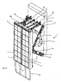
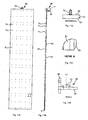
- Figures 1A , 1B , 8A , 8B and 8C illustrates a maritime fender assembly 1 for a berthing structure (not shown), such as a pier, wharf, jetty, dolphin structure, goods terminal, passenger terminal etc.
- a berthing structure such as a pier, wharf, jetty, dolphin structure, goods terminal, passenger terminal etc.
- the fender assembly 1 has a frame 3 which releasably receives removable panel assemblies 5 via engagement means 4.
- the frame 3 is mounted via an energy absorbing fender element 11 to a base 9 which in turn is fixed to the berthing structure.
- Fender element 11 allows the frame 3 to move relative to the base 9 and berthing structure when impacted by berthing vessels.
- outwardly facing wear pads 7 on the panel assemblies 5 provide a contact surface for a hull of a vessel, and kinetic energy from impact of the hull is transmitted to the frame 3 and absorbed by the fender element 11.
- the panel assemblies 5 are disengaged from the frame 3 to allow for their removal for servicing and/or replacement. This can be done while the remaining parts of the fender assembly 1, such as the frame 3, fender element 11 and base 9 are maintained in situ.
- the fender assembly 1 is also provided with a plurality of support chains 15, each support chain extending between mounting points such as 19 and 21 respectively located on the frame 3 and base 9..
- the support chains 15, in use, are positioned and tensioned to maintain the frame assembly 3 (and the panel assemblies 5 carried thereby) in a selected position and/or orientation.
- a detensioning system 150 for detensioning the support chains 15 to allow for their removal for replacement or other maintenance.
- the detensioning system 150 includes one or more detensioning chains 23 that are mountable adjacent to the support chain mounting points 19, 21 via first and second detensioner mounting points 25 and 27 provided respectively on the frame 3 and base 9. When the support chains 15 need to be removed, detensioning chains are secured in place between the detensioner mounting points and then shortened to relieve tension in the support chain 15.
- FIG. 1 a removable access platform 13 is shown. Platform 13 is removably located at the fender assembly and secured to the berthing facility to provide a working area for workers to access relevant components of the fender assembly 1.
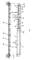
- the frame 3 has a substantially hollow rectangular prism frame body 31 constructed from stainless steel or other material suitable for use in a marine environment.
- the frame body 31 has two main planar surfaces on opposite faces: an outwardly facing surface 33 facing away from the berthing structure, and an inwardly facing surface 35 facing towards the berthing structure.
- the outwardly facing surface 33 is provided with a low friction surface 37 , which provide a low friction surface for panel assemblies 5 to slide against during removal and replacement, as well as an abutment surface for transmission of an impact force from the panels 5 to the frame 3.
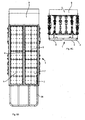
- the low friction surface 37 is provided by a plurality of inner wear pads 36 arranged into two arrays separated by the central channels 41B as discussed below with reference to Figures 14A-14D .
- Each inner wear pad 36 is made of UHMWPE or HDPE and has a plurality of apertures 30 for affixing the inner wear pad 36 to the frame 3 by fasteners 34, as shown in Figure 14D .
- M16 SS316 studs are welded to the frame 3.
- the low friction surface 37 e.g. the individual inner wear pads 36
- the low friction surface 37 may be coloured to contrast with other components of the fender assembly 1, and in particular with the colour of the outwardly facing wear pads 9. This assists in easy visual identification of a fender assembly 1 which is undergoing maintenance and has a panel 5 removed.
- the inner wear pads 36 may be replaced periodically due to the frictional wear or change from contact with the panel assemblies 5. However this will generally be less frequent then replacement of the outwardly facing wear pads 7.
- a frame assembly mount 39 At the centre of the inwardly facing surface 35 is a frame assembly mount 39, where the frame 3 is mounted to the fender element 11.
- the frame assembly mount 39 provides the interface for transmission of force and energy from the frame 3 to the fender element 11.
- the inwardly facing surface 35 of the frame 3 is also provided with a plurality of support chain mounting points 19, each with respective adjacent detensioner mounting points 25.
- spigots 138 At the top portion of the frame 3, there is a plurality of vertically extending spigots 138, best shown in Figure 1B and 8A . These spigots 138 are received in apertures 136 of the removable access platform 13, which will be described in more detail below.
- a rope guard 38 extends from the lower portions of the frame body 31 to prevent entanglement of mooring lines with the fender assembly 1.
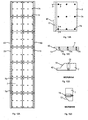
- each pair of opposing channels 41 includes an edge channel 41A disposed proximate to a vertical side edge of the frame 3, and a relatively central channel 41B running down the frame 3.
- Each edge channel 41A runs substantially the length of the frame 3 and opens towards its associated central channel 41B.
- Each central channel 41B also runs the substantial length of the frame 3 and opens towards its associated edge channel 41A.
- At the base of the frame 3 is an outwardly extending lip 32 for abutting against and supporting the panel assemblies 5 when in place.
- each pair of opposing channels 41 is adapted to receive a pair of opposite side edges 42 of a panel assembly 5 which slots into place in the channels 41 and rests on the lip 32.
- the bracket assembly includes a first bracket 45 fixed to the top portion of the frame body 31.
- the first bracket 45 is provided with a plurality of fastening apertures 52 to enable fasteners (e.g. bolts 48) to pass through.
- the bracket assembly also includes a second bracket 46 having a plurality of fastening apertures 54 corresponding to the fastening apertures 52 of the first bracket 45.
- Removable bracket 46 further includes a panel assembly abutment surface 47 for abutment with a top portion 57 of a panel assembly 5.
- the vertically oriented bolts 49 are received into the removable brackets 46 via threaded apertures.
- bracket assembly 43 secures a panel assembly 5 in place by fastening the removable bracket 46 to the fixed bracket 45, whereby the panel assembly abutment surface 47 prevents the panel assembly 5 from moving out of place.
- Each panel assembly 5 has a substantially flat panel plate 51 constructed of stainless steel as illustrated in Figures 11A-11E .
- the panel plate 51 has an inner surface 53, which when the panel assembly 5 is received by the frame 3 abuts the inner wear pads 37.
- the panel plate 51 has an outer surface 55 to which the fender face is affixed.
- the fender face includes an array of outwardly facing wear pads 7 which are releasably mounted to the plate 51 fasteners 71 (such as bolts and nuts) as shown in Figures 10C and 11C .
- At the opposite peripheral sides of the panels 5 are vertical side edges 42, which are slidingly receivable into the channels 41 along a vertical sliding axis along the channel to engage the panel 5 with the frame 3.
- the outwardly facing wear pads 7 includes an angled section 72 leading to the vertical side edges 42.
- This angled section 72 assists in guiding the vertical side edges 42 in to the channels 41 when sliding the panel assembly 5 into engagement with the channels.
- This chamfer extends approximately 2 metres from the bottom edge of each panel 5.
- a jacking bracket 59 is provided at the top 57 of the panel 5 as best shown in Figures 11A, 11B and 11C .
- the jacking bracket 59 extends rearwardly from the panel so as, in use, to extend over a section of the frame 3.
- the jacking bracket 59 has an internally threaded aperture 61 having an aperture axis A which is parallel to the vertical sliding plane of the panel assembly 5 (i.e. the plane along which the panel is slid into receiving channels 41).
- the lower opening of the threaded aperture 61 faces a jack engagement surface 63 on the top portion of the frame body 31.
- the threaded aperture 61 allows a threaded rod/jack (not shown) to be received therein, whereby movement of the rod through the aperture 61 causes an end surface of the rod to impart a force against the jack engagement surface 63.
- the resulting force separates the jacking bracket 59 and the panel 5 away from the jack engagement surface 63 of the frame body 31 in a direction along the vertical sliding plane. This can be of assistance where the panel assembly 5 has become stuck in place in the frame 3 due to marine growth for instance.
- a lifting lug 65 is provided at the top portion 57 of the panel 5, and in the illustrated embodiment, extends from the jacking bracket 59.
- the lifting lug 65 allows the panel assembly 5 to be attached to a hoist to lift the panel assembly 5 for extraction from and insertion into the fender assembly 1.
- a stop 67 is provided to on the panel 5 to prevent downward vertical movement of the panel 5 beyond a desired position relative to the frame 3.
- the stop 67 may be a bottom surface of the jacking bracket 59, which, when the panel 5 is at the lowermost desired position is in abutment with the top portion of the frame body 31, as best illustrated in Figures 6 and 11E .
- the stop 67 is functionally similar to the lip 32 described above, and may also form part of the engagement means 4.
- the outwardly facing wear pads 7 function as a sacrificial part of the fender assembly 1 as best shown in Figures 12A-12E .
- the outwardly facing wear pads 7 are made of a low friction material designed to avoid (as far as possible) damage to objects that are expected to bear against them, such as the hull of vessels.
- the outwardly facing wear pads 7 may be made of a plastic material such as Ultra-high-molecular-weight polyethylene (UHMW-PE) or HDPE.
- UHMW-PE Ultra-high-molecular-weight polyethylene
- the wear pads 7 have a plurality of apertures 74 to receive fasteners 71 for securing the wear pads 7 to the panel plate 51.
- the fender element 11 of the present embodiment is a substantially hollow cylindrical form made of a resilient elastomeric material, such as rubber, such as SCN super cone fender or SCK super cell fender. These are the most commonly used fender types for large fender systems supplied by Trelleborg AB and come in a variety of sizes from 300mmH to 3000mmH.
- the fender element 11 is designed to absorb and cushion force, momentum and energy transmitted via the moveable frame 3 and panel assemblies 5. Typically this will be from an impact of the hull of a vessel to the panels 5. During impact, the fender element 11 deforms to allow movement of the frame 3 and panel assemblies 5. After impact, the resilience of the material allows the fender element 11 to rebound back to the pre-impact shape state.
- one end of the fender element 11 is attached to the mounting location 39 of the frame 3, and the opposite end attached to the base 9. At least part of the weight of the frame 3 and panels 5 in this embodiment is supported by the fender element 11 (the remainder of the weight being supported by support chains 15 as discussed below).
- the fender element 11 also provides a bias force to the frame 3, which is countered by a reactive tension force in the support chains 15 discussed below.
- This bias force includes a component biasing the frame 3 outwardly away from the base 9.
- the base 9 is fixed to the berthing structure, thus forming a "fixed" part of the fender assembly 1 relative to the berthing structure. This is in contrast to the "moveable" frame 3 and panel assemblies 5.
- the base 9 provides an attachment point for the fender element 11.
- the base also provides support chain mounting points 21 and detensioner system mounting points 27.
- the base 9 as the "fixed" part of the fender assembly 1 also provides a stable support for the access platform 13 during maintenance,
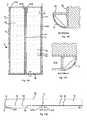
- the fender 1 is provided with a series of bumper guards and covers as illustrated in Figure 4 .
- these include a top cover 73 over the bracket assembly 43, and rubber corner and edge protectors 75 and 77 for providing a bumper guard to protect the frame from vessel contact.
- These covers 73 and guards 75, 77 may be modular and replaceable.
- a rope guard 38 is also provided below the fender to reduce the likelihood of mooring (or other) ropes/chains being caught behind the fender 1.
- a plurality of support chains 15 assist in maintaining the frame 3 and panel assemblies 5 in a desired position and orientation, and are normally under tension.
- the tension in the support chains 15 may be due to any one of weight of the frame 3 and panel assemblies 5, bias force of the energy absorbing means 11, or external forces acting on the frame 3 and panels 5 such as waves, wind or impact of the hull of a vessel.
- Tension chain 151 is a support chain 15 for maintaining the frame 3 in a substantially vertical orientation, in particular preventing the frame 3 and the outwardly facing wear pads 7 from facing downwards towards the water.
- Uplift chain 153 is a support chain 15 for maintaining the frame 3 in a substantially vertical orientation, in particular preventing the frame and the outwardly facing wear pads 7 from displacing upwards during a vessel berthing operation.
- Weight chain 155 is a support chain 15 for supporting the weight of the frame 3 and panels 5, to prevent the frame 3 and panel assemblies 5 from displacing downwards.
- a component of the tension in the above described support chains 15 also assists in preventing the frame 3 and panel assemblies 5 from displacing outwards away from the base 9.
- Shear chains are another type of support chain 15 that may be used. Shear chains provide a tension force to prevent the frame 3 from rotating from side to side, and are typically arranged in a cross pattern when the fender assembly is viewed from the top.
- the support chains 15 may also include a length adjustable element 157.
- the length adjustable element 157 allows adjustment of the desired length of the support chains 15 to achieved the desired position/orientation of the frame 3 and panel assemblies 5.
- one or more detensioning chains 23 are provided as best illustrated in Figures 8A , 8C and 15 .
- a plurality of detensioning chains are provided, one to match each support chain that needs to be detensioned.
- Each detensioning chain has a first end 159 receivable to a frame-side detentioner mounting point 25, and a second end 161 receivable to the base-side detentioner mounting point 27.
- a length adjustable component 163 is disposed between the detensioner ends 159 and 161, and when activated, draws the ends 159 of the detensioner 161 together.
- the length adjustable component 163 in one embodiment includes a hydraulic cylinder to provide force to pull the ends 159, 161 together. When deactivated, the hydraulic cylinder may slowly decrease the hydraulic force to allow the ends 159, 161, and attached components of the fender assembly 1 to be separated from each other in a controlled manner.
- the frame-side and base-side detensioner mounting points 25 and 27 of the present embodiment are mounted adjacent to the relevant support chain mounting points. It will be appreciated, however, that alternative mounting points could be used provided their position allows the detensioner to detension the relevant support chain on operation.
- the maintenance system 100 for the fender assembly 1 includes a hoist (not shown).
- the hoist may be in the form of a crane or other machinery capable of lifting loads vertically. This may include a mobile crane driven or otherwise transported to the either the berthing assembly or water adjacent the fender assembly 1.
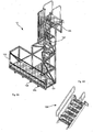
- a removable access platform 13 may be provided.
- the removable access platform 13 includes mounting zone 135 for locating the access platform 13 with the base 9 of the fender assembly 1.
- a working area 131 is provided at a level below the mounting zone 135, whereby the working area is accessible by a ladder 137.
- the working area 131 is located to provide access for workers to components of the fender assembly 1, including the lifting lug 65, jacking bracket 59 and bracket assembly 43.
- a safety barrier 133 surrounds the working area 131 and ladder 137.
- the removable access platform 13 is provided with a plurality of flanges each having respective apertures 136.
- the apertures 136 receive the corresponding spigot 138 extending upwardly from the frame 3. This ensures that the access platform 13, and the working area 131 is located correctly in the desired position relative to components of the fender assembly 1. This arrangement may also ensure stability of the access platform 13 and/or the frame 3 during maintenance operations.
- a gangway 139 may be provided as a bridge between the access platform 13 and the pier.
- this provides a stable work area in contrast with attempting to access components of the fender assembly 1 from a vessel on the water.
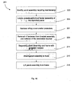
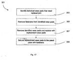
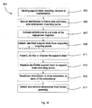
- FIG. 16 - 19 show respectively: a flowchart 201 depicting the steps involved in removing a panel assembly 5; a flow chart 301 depicting the steps involved in maintaining a panel assembly 5; a flow chart 401 depicting the steps involved in replacing a panel assembly; and a flowchart 501 depicting the steps involved in maintaining one or more support chains 23.
- a fender assembly having a panel assembly 5 that requires maintenance is identified. Identification of the panel assembly 5 may be in accordance with a maintenance schedule and cycle, whereby panel assemblies 5 (or, more particularly, the outwardly facing wear pads 7 carried thereby) are periodically removed and inspected. Alternatively, the inspection of the plurality of the fender assemblies 1 and panels 5 in situ may result in identification of panels 5 that warrant removal and further inspection and/or servicing.
- Workers at the working area 131 may then begin the process of releasing the identified panel assembly 5 from engagement from the frame 3. This includes removal of the top cover 73 and corner protectors 75 from bracket assembly 43 at step 207 (as shown in Figures 4 and 5 ).
- the fasteners 48 can then be removed, to allow removal of the removable bracket 46 from the bracket assembly 43 as shown in Figure 6 .
- a threaded rod/jack (not shown) may then be rotated into threaded aperture 61, whereby the end surface of the rod imparts a force against the jack engagement surface 63.
- This resultant force separates the jacking bracket 59 and the attached panel assembly 5 away from the frame body 31 by a small distance, for example 50mm. This advantageously assists to dislodge any marine growth than may impair easy separation between the panel assembly 5 and the frame 3.
- the jacking screw may be part of a hydraulic jack lowered by the hoist.
- the panel assembly 5 is then attached to the hoist via the lifting lug 65, and at step 215 the panel assembly 5 is lifted vertically from the frame 3.
- panel assembly 5 has a guided path along a vertical sliding plane as it is slidingly disengaged from the frame 3, as best illustrated in Figure 2 .
- the panel assemblies 5 are inspected to identify individual wear pads 7 that need replacement.
- the fasteners 71 of the identified wear pads 7 are removed from the panel plate 51.
- the identified wear pads 7 are then removed, and replaced with replacement wear pads 7 as shown at step 307.
- the replacement wear pads 7 are then secured to the panel plate 51 with fasteners.
- inspection and servicing may be performed in the vicinity of the respective fender assembly 1.
- the maintenance steps need not be carried out as part of the panel assembly replacement operation, but can conducted in a workshop at another time and location where it will not disrupt operation of the berths.
- the replacement panel assembly 5 is hoisted by the lifting lug 65 so that it is positioned vertically above the opposing channels 41 of the frame 3.
- the panel assembly 5 typically with the assistance of workers, is guided and lowered so the opposite edges 42 are received into the channels 41. Further lowering of the panel assembly 5 by the hoist allows the panel assembly 5 to slidingly engage into the desired position with respect to the frame 3. The stop 67 ensures the panel assembly 5 cannot be lowered past the desired position.
- the panel assembly 5 is further engaged with the frame by fastening the removable bracket 46 to the bracket assembly 43 to prevent movement of the panel assembly 5 relative to the frame.
- step 409 the top cover 73 and/or corner protectors are then replaced.
- the access platform 13 (if in use) is removed from the fender assembly 1, and the fender assembly 1 and berth may resume normal operation.
- the removal and replacement of the panel assembly 5 may be performed during the downtime period of the berth between vessels leaving and entering the berth during a normal operation cycle. This minimises the disruption fender maintenance may have on vessel loading/unloading operations. Therefore to perform maintenance on a plurality of fender assemblies 1 on a pier, it may be advantageous to schedule maintenance on a small number of fender assemblies 1 during each downtime period, so that maintenance on the entire plurality of fender assemblies 1 would be spread over several cycles of vessels leaving and entering the berth.
- a support chain 15 requiring maintenance or replacement is identified.
- the ends 159, 161 of the detensioner 23 are secured in the frame-side and base-side detensioner mounting points 25, 27.
- the detensioner 23 is then activated so that the length adjustable component 163 pulls the ends 159, 161 of the detensioner 23 together.
- the frame 3 is pulled by the detensioner towards the base 9, with the detensioner 23 itself in tension.
- step 509 the identified support chain 15 (now relieved of tension), is detached from respective support chain mounting points 19 and 21.
- the support chain 15 may be inspected, serviced or disposed.
- a serviceable support chain is attached to the support chain mounting points 19, 21 at step 513.
- the installed detensioner is deactivated to allow separation of the ends 159, 161 of the detensioner 23. This reduces the tension in the detensioner 23 and allows the serviceable support chain 15 to take up tension.
- the detensioner is deactivated by gradually reducing the force/pressure in the hydraulic cylinder of the length adjustable component 163 so that the decrease in tension in the detensioner 23 and consequential increase in tension of the support chain 15 occurs in a gradual controlled manner.
- the detensioner 23 is detached and removed from the fender assembly 1 at step 517.
- An advantage of the disclosed embodiments is to allow servicing of the wear pads 7 without disassembly and removal of other components of the fender assembly such as the frame, or energy absorbing unit. By leaving the frame and other components in situ, less labour and machinery (and hence less time) is required to service the maritime fender assembly.
- maritime fender assemblies can be large devices with the frames weighing in the order of tonnes. By removing only the panels and associated pads, a smaller hoist having a smaller lifting capacity can be used. This can lead to faster set-up times for the hoist and other maintenance equipment such as the access platform. As the panels are relatively lighter and smaller, there is a reduced handling requirement. Such applications are also relevant for older berths that have limited weight restrictions on their offshore access jetties, thus making it impossible to transport a regular fender frame to shore for maintenance without the use of costly barges and floating crane vessels.
- Another advantage may be obtained by scheduling fender maintenance between the period vessels leave and enter the dock. This would allow maintenance of the fender assemblies to be conducted without affecting or significantly affecting normal vessel operations at the berth.
- the detensioners advantageously assist removal of the support chains by relieving tension in the support chains before removal. This allows easier removal of the support chains, and may improve the safety for workers who can avoid or minimise handling of the support chains that are under tension.
- the detensioners may also be advantageously used to assist in restoring tension in the support chains during installation.
- the engagement means 4 may comprise of a range of means to engage the panel assembly 5 to the frame 3.
- the panel assemblies 5 may slide into engagement with the frame 3 along an axis perpendicular to the outwardly facing surface 33 of the frame 3.
- the panels 5 may slide into engagement with the frame 3 along a horizontal axis parallel to the outwardly facing surface 33.
- the above described fender assembly 1 includes two panel assemblies 5 received by a single frame 3. Variations may include other combinations, including one panel assembly for each frame, or a plurality of panel assemblies 5 for each frame 3. In yet another variation, there may be provided one panel assembly engaged with two or more frames 3.
- the panel assemblies 5 may be a substantially monolithic component, such as a single piece of rubber with at least one outwardly facing surface as a wear pad.
- the fender element 11 is an elastomeric body which relies on deformation of the resilient material.
- the energy absorbing unit may be of other forms, such as a pressurised body (e.g. an "airbag”), a system of springs, pneumatic or hydraulic systems etc.
- the fender element absorbs energy transmitted from the moveable frame 3, whilst allowing at least some displacement of the frame 3 relative to the base 9 and berthing structure.
- the fender element 11 described above also functions to support at least part of the weight of the frame 3 and panels 5.
- Variations of the fender assembly may include other weight supporting elements so the frame 3 for the frame can be moveably mounted to the berthing structure. In such variations, the energy absorbing unit is not required to support the weight of the frame 3 or panels 5.
- the detensioner 23 described above includes a hydraulic cylinder to pull the ends 159, 161 together.
- other forms of the length adjustable component 163 may be used, including a threaded jack, a ratchet system, pneumatic system etc.
Landscapes
- Engineering & Computer Science (AREA)
- General Engineering & Computer Science (AREA)
- Ocean & Marine Engineering (AREA)
- Mechanical Engineering (AREA)
- Structural Engineering (AREA)
- Civil Engineering (AREA)
- Environmental & Geological Engineering (AREA)
- Body Structure For Vehicles (AREA)
- Packaging Of Machine Parts And Wound Products (AREA)
- Bridges Or Land Bridges (AREA)
- Aiming, Guidance, Guns With A Light Source, Armor, Camouflage, And Targets (AREA)
- Connection Of Plates (AREA)
- Vibration Prevention Devices (AREA)
- Refuge Islands, Traffic Blockers, Or Guard Fence (AREA)
Priority Applications (3)
| Application Number | Priority Date | Filing Date | Title |
|---|---|---|---|
| PT128809811T PT2872699T (pt) | 2012-07-11 | 2012-07-11 | Uma defensa marítima e método de manutenção associado |
| TR2018/07115T TR201807115T4 (tr) | 2012-07-11 | 2012-07-11 | Denizcilikte kullanılan bir usturmaça ve ilgili bakım yöntemi. |
| PL12880981T PL2872699T3 (pl) | 2012-07-11 | 2012-07-11 | Morski odbijacz i związany z nim sposób konserwacji |
Applications Claiming Priority (1)
| Application Number | Priority Date | Filing Date | Title |
|---|---|---|---|
| PCT/AU2012/000832 WO2014008525A1 (en) | 2012-07-11 | 2012-07-11 | A maritime fender and associated method of maintenance |
Publications (3)
| Publication Number | Publication Date |
|---|---|
| EP2872699A1 EP2872699A1 (en) | 2015-05-20 |
| EP2872699A4 EP2872699A4 (en) | 2016-08-31 |
| EP2872699B1 true EP2872699B1 (en) | 2018-02-21 |
Family
ID=49915235
Family Applications (1)
| Application Number | Title | Priority Date | Filing Date |
|---|---|---|---|
| EP12880981.1A Not-in-force EP2872699B1 (en) | 2012-07-11 | 2012-07-11 | A maritime fender and associated method of maintenance |
Country Status (17)
| Country | Link |
|---|---|
| US (2) | US20150292173A1 (enExample) |
| EP (1) | EP2872699B1 (enExample) |
| JP (1) | JP6390974B2 (enExample) |
| CN (1) | CN104619919B (enExample) |
| AU (1) | AU2013200976B2 (enExample) |
| BR (1) | BR112015000490B1 (enExample) |
| CA (1) | CA2878671C (enExample) |
| DK (1) | DK2872699T3 (enExample) |
| ES (1) | ES2680651T3 (enExample) |
| NO (1) | NO2872699T3 (enExample) |
| PH (1) | PH12015500035B1 (enExample) |
| PL (1) | PL2872699T3 (enExample) |
| PT (1) | PT2872699T (enExample) |
| SG (1) | SG11201408765PA (enExample) |
| TR (1) | TR201807115T4 (enExample) |
| TW (1) | TWI610848B (enExample) |
| WO (1) | WO2014008525A1 (enExample) |
Families Citing this family (11)
| Publication number | Priority date | Publication date | Assignee | Title |
|---|---|---|---|---|
| US9765494B2 (en) * | 2015-05-21 | 2017-09-19 | Sharon Kedar | Marine fender system |
| FI128806B (fi) * | 2017-07-28 | 2020-12-31 | Novafiber Oy | Menetelmä ja järjestely satamafenderin suojaamiseksi aluksen kiinnitysköysien takertumiselta |
| CN107792315B (zh) * | 2017-10-18 | 2019-12-13 | 天津魁普重工机械有限公司 | 一种用于船舶停靠的平行移动护板结构 |
| JP7134459B2 (ja) * | 2018-01-18 | 2022-09-12 | シバタ工業株式会社 | 防舷材の交換方法 |
| CN111705749A (zh) * | 2020-06-29 | 2020-09-25 | 长沙开湖设备有限公司 | 一种避免桥墩正向撞击的吸能器 |
| KR102570695B1 (ko) * | 2021-09-24 | 2023-08-24 | 현대제철 주식회사 | 선박용 부두 완충장치 |
| CN113958119B (zh) * | 2021-11-17 | 2022-10-04 | 中建八局第二建设有限公司 | 一种用于木模板早拆体系的组合托撑 |
| JP7782335B2 (ja) * | 2022-03-23 | 2025-12-09 | 中国電力株式会社 | 係留ロープ保護用器具 |
| CN115214857B (zh) * | 2022-07-12 | 2023-06-27 | 江苏科技大学 | 一种中大型船舶防撞气囊的动态展开装置 |
| IT202300015444A1 (it) * | 2023-07-24 | 2025-01-24 | Ncl Corp Ltd | Apparato con bracci di rimorchio laterali per mezzi navali |
| CN118087480B (zh) * | 2024-03-26 | 2024-11-26 | 上海勘测设计研究院有限公司 | 一种海上平台上部组块的护舷系统及其制造方法 |
Family Cites Families (19)
| Publication number | Priority date | Publication date | Assignee | Title |
|---|---|---|---|---|
| US3937170A (en) * | 1974-10-29 | 1976-02-10 | Drewett Glen E | Bumper guard and arrangement for water covered areas |
| JPS5621996A (en) * | 1979-07-31 | 1981-02-28 | Seibu Polymer Kasei Kk | Fender |
| JPS5726426U (enExample) * | 1980-07-17 | 1982-02-10 | ||
| JPS5796215U (enExample) * | 1980-11-30 | 1982-06-14 | ||
| GB2091376B (en) | 1980-12-05 | 1985-02-06 | Lasalle Marine Inc | Replaceable marine fender mechanism |
| JPS60111927U (ja) * | 1983-12-29 | 1985-07-29 | 本州四国連絡橋公団 | 緩衝装置の取付構造 |
| US4900192A (en) * | 1988-09-28 | 1990-02-13 | Wood James E | Dock boat well protective bumper |
| US5361715A (en) * | 1993-06-09 | 1994-11-08 | Svedala Industries, Inc. | Marine dock fender contact surface attaching boss |
| JPH08301188A (ja) * | 1995-05-09 | 1996-11-19 | Masaki Yamamoto | キャップ式カラー防舷材 |
| JPH10266166A (ja) * | 1997-03-28 | 1998-10-06 | Sumitomo Rubber Ind Ltd | 防舷材用補助チェーン |
| CA2322574C (en) * | 1998-03-10 | 2007-12-18 | Acta Maritime Development Corporation | Container transfer terminal system and method |
| US6685395B1 (en) * | 2002-07-31 | 2004-02-03 | Pawling Corporation | Piling fender |
| US7287484B2 (en) * | 2003-05-01 | 2007-10-30 | David Charles Landry | Berthing method and system |
| CN100503360C (zh) * | 2004-03-22 | 2009-06-24 | 中国船舶工业第七○八研究所 | 液压驱动高反力缓冲装置 |
| WO2006067237A1 (es) * | 2004-12-17 | 2006-06-29 | Prosertek, S.L. | Sistema de defensa regulable en altura para atraques de buques |
| WO2006125277A1 (en) * | 2005-05-27 | 2006-11-30 | Harbour & Marine Engineering Pty Ltd | Fender monitoring system |
| KR100641975B1 (ko) * | 2006-05-23 | 2006-11-02 | 주식회사 국민씨아이 | 섬유강화 복합소재 팬더 패널을 구비한 안벽 구조물의방충구조물 |
| CN101758807A (zh) * | 2008-11-25 | 2010-06-30 | 武汉福来商贸有限公司 | 可拆卸式车船用弹性阻力防撞板 |
| CN101428681A (zh) * | 2008-12-09 | 2009-05-13 | 闫海军 | 鼓型橡胶护舷 |
-
2012
- 2012-07-11 NO NO12880981A patent/NO2872699T3/no unknown
- 2012-07-11 TR TR2018/07115T patent/TR201807115T4/tr unknown
- 2012-07-11 DK DK12880981.1T patent/DK2872699T3/en active
- 2012-07-11 BR BR112015000490-3A patent/BR112015000490B1/pt active IP Right Grant
- 2012-07-11 US US14/414,092 patent/US20150292173A1/en not_active Abandoned
- 2012-07-11 CN CN201280074590.1A patent/CN104619919B/zh not_active Expired - Fee Related
- 2012-07-11 CA CA2878671A patent/CA2878671C/en active Active
- 2012-07-11 JP JP2015520769A patent/JP6390974B2/ja active Active
- 2012-07-11 WO PCT/AU2012/000832 patent/WO2014008525A1/en not_active Ceased
- 2012-07-11 AU AU2013200976A patent/AU2013200976B2/en active Active
- 2012-07-11 PL PL12880981T patent/PL2872699T3/pl unknown
- 2012-07-11 PT PT128809811T patent/PT2872699T/pt unknown
- 2012-07-11 EP EP12880981.1A patent/EP2872699B1/en not_active Not-in-force
- 2012-07-11 ES ES12880981.1T patent/ES2680651T3/es active Active
- 2012-07-11 SG SG11201408765PA patent/SG11201408765PA/en unknown
-
2013
- 2013-06-27 TW TW102123011A patent/TWI610848B/zh not_active IP Right Cessation
-
2015
- 2015-01-06 PH PH12015500035A patent/PH12015500035B1/en unknown
-
2017
- 2017-11-30 US US15/828,268 patent/US20180155889A1/en not_active Abandoned
Non-Patent Citations (1)
| Title |
|---|
| None * |
Also Published As
| Publication number | Publication date |
|---|---|
| PT2872699T (pt) | 2018-06-14 |
| TR201807115T4 (tr) | 2018-06-21 |
| PL2872699T4 (pl) | 2018-10-31 |
| EP2872699A4 (en) | 2016-08-31 |
| AU2013200976A1 (en) | 2014-01-30 |
| SG11201408765PA (en) | 2015-01-29 |
| ES2680651T3 (es) | 2018-09-10 |
| JP6390974B2 (ja) | 2018-09-19 |
| EP2872699A1 (en) | 2015-05-20 |
| BR112015000490B1 (pt) | 2021-02-09 |
| CA2878671C (en) | 2019-02-26 |
| CN104619919B (zh) | 2018-11-27 |
| US20180155889A1 (en) | 2018-06-07 |
| TW201410540A (zh) | 2014-03-16 |
| TWI610848B (zh) | 2018-01-11 |
| PH12015500035A1 (en) | 2015-02-23 |
| BR112015000490A2 (pt) | 2017-06-27 |
| HK1209165A1 (en) | 2016-03-24 |
| CA2878671A1 (en) | 2014-01-16 |
| JP2015523482A (ja) | 2015-08-13 |
| WO2014008525A1 (en) | 2014-01-16 |
| PH12015500035B1 (en) | 2015-02-23 |
| PL2872699T3 (pl) | 2018-10-31 |
| CN104619919A (zh) | 2015-05-13 |
| NO2872699T3 (enExample) | 2018-07-21 |
| US20150292173A1 (en) | 2015-10-15 |
| AU2013200976B2 (en) | 2014-04-10 |
| DK2872699T3 (en) | 2018-06-06 |
Similar Documents
| Publication | Publication Date | Title |
|---|---|---|
| EP2872699B1 (en) | A maritime fender and associated method of maintenance | |
| CN109896408B (zh) | 橙汁船货仓甲板总段吊装工装 | |
| US20160001858A1 (en) | Submersible offshore positionable frame | |
| US9765494B2 (en) | Marine fender system | |
| US9840309B2 (en) | Mooring arrangement | |
| JP7189826B2 (ja) | 港湾の岸壁における安全管理方法及び安全管理システム | |
| HK1209165B (zh) | 船用碰垫及相关维护方法 | |
| KR20150054240A (ko) | 함선 설치구조 | |
| KR20100009006U (ko) | 선박용 고박장치 | |
| EP3250759B1 (en) | Fender system | |
| JP7174424B2 (ja) | 岸壁構造体及び防舷材の運用方法 | |
| CN118871642A (zh) | 海上船舶着陆护舷 | |
| CN119162961B (zh) | 一种靠泊与装卸分离的高桩码头 | |
| CN215763979U (zh) | 一种水力除锈管线过桥装置 | |
| KR101086057B1 (ko) | 낙광물의 유실을 방지하는 항만하역장치 및 그 방법 | |
| KR102804898B1 (ko) | 해상풍력 유지 보수선용 접안장치 | |
| KR20070110380A (ko) | 사다리 | |
| CN223562078U (zh) | 一种隔离水平力的高桩码头 | |
| JP3383796B2 (ja) | 防舷材の施工足場装置 | |
| CN209797229U (zh) | 橙汁船货仓甲板总段吊装工装 | |
| WO2025206960A1 (en) | Impact protection barrier systems and deployment mechanisms | |
| GB2070554A (en) | Method and apparatus for lifting a heavy load from a floating vessel | |
| Morgan | Bulk materials handling berths | |
| GB2561704A (en) | Storage frame and method of use thereof |
Legal Events
| Date | Code | Title | Description |
|---|---|---|---|
| PUAI | Public reference made under article 153(3) epc to a published international application that has entered the european phase |
Free format text: ORIGINAL CODE: 0009012 |
|
| 17P | Request for examination filed |
Effective date: 20150202 |
|
| AK | Designated contracting states |
Kind code of ref document: A1 Designated state(s): AL AT BE BG CH CY CZ DE DK EE ES FI FR GB GR HR HU IE IS IT LI LT LU LV MC MK MT NL NO PL PT RO RS SE SI SK SM TR |
|
| AX | Request for extension of the european patent |
Extension state: BA ME |
|
| DAX | Request for extension of the european patent (deleted) | ||
| RA4 | Supplementary search report drawn up and despatched (corrected) |
Effective date: 20160728 |
|
| RIC1 | Information provided on ipc code assigned before grant |
Ipc: E02B 3/26 20060101AFI20160722BHEP |
|
| RAP1 | Party data changed (applicant data changed or rights of an application transferred) |
Owner name: TRELLEBORG MARINE SYSTEMS MELBOURNE PTY LTD |
|
| GRAP | Despatch of communication of intention to grant a patent |
Free format text: ORIGINAL CODE: EPIDOSNIGR1 |
|
| STAA | Information on the status of an ep patent application or granted ep patent |
Free format text: STATUS: GRANT OF PATENT IS INTENDED |
|
| INTG | Intention to grant announced |
Effective date: 20170905 |
|
| GRAS | Grant fee paid |
Free format text: ORIGINAL CODE: EPIDOSNIGR3 |
|
| GRAA | (expected) grant |
Free format text: ORIGINAL CODE: 0009210 |
|
| STAA | Information on the status of an ep patent application or granted ep patent |
Free format text: STATUS: THE PATENT HAS BEEN GRANTED |
|
| AK | Designated contracting states |
Kind code of ref document: B1 Designated state(s): AL AT BE BG CH CY CZ DE DK EE ES FI FR GB GR HR HU IE IS IT LI LT LU LV MC MK MT NL NO PL PT RO RS SE SI SK SM TR |
|
| REG | Reference to a national code |
Ref country code: GB Ref legal event code: FG4D |
|
| REG | Reference to a national code |
Ref country code: CH Ref legal event code: EP |
|
| REG | Reference to a national code |
Ref country code: DE Ref legal event code: R096 Ref document number: 602012043233 Country of ref document: DE Ref country code: AT Ref legal event code: REF Ref document number: 971858 Country of ref document: AT Kind code of ref document: T Effective date: 20180315 |
|
| REG | Reference to a national code |
Ref country code: IE Ref legal event code: FG4D |
|
| REG | Reference to a national code |
Ref country code: DK Ref legal event code: T3 Effective date: 20180531 Ref country code: NL Ref legal event code: FP |
|
| REG | Reference to a national code |
Ref country code: SE Ref legal event code: TRGR |
|
| REG | Reference to a national code |
Ref country code: PT Ref legal event code: SC4A Ref document number: 2872699 Country of ref document: PT Date of ref document: 20180614 Kind code of ref document: T Free format text: AVAILABILITY OF NATIONAL TRANSLATION Effective date: 20180606 |
|
| REG | Reference to a national code |
Ref country code: LT Ref legal event code: MG4D |
|
| REG | Reference to a national code |
Ref country code: AT Ref legal event code: MK05 Ref document number: 971858 Country of ref document: AT Kind code of ref document: T Effective date: 20180221 |
|
| REG | Reference to a national code |
Ref country code: FR Ref legal event code: PLFP Year of fee payment: 7 |
|
| PG25 | Lapsed in a contracting state [announced via postgrant information from national office to epo] |
Ref country code: FI Free format text: LAPSE BECAUSE OF FAILURE TO SUBMIT A TRANSLATION OF THE DESCRIPTION OR TO PAY THE FEE WITHIN THE PRESCRIBED TIME-LIMIT Effective date: 20180221 Ref country code: CY Free format text: LAPSE BECAUSE OF FAILURE TO SUBMIT A TRANSLATION OF THE DESCRIPTION OR TO PAY THE FEE WITHIN THE PRESCRIBED TIME-LIMIT Effective date: 20180221 Ref country code: HR Free format text: LAPSE BECAUSE OF FAILURE TO SUBMIT A TRANSLATION OF THE DESCRIPTION OR TO PAY THE FEE WITHIN THE PRESCRIBED TIME-LIMIT Effective date: 20180221 Ref country code: LT Free format text: LAPSE BECAUSE OF FAILURE TO SUBMIT A TRANSLATION OF THE DESCRIPTION OR TO PAY THE FEE WITHIN THE PRESCRIBED TIME-LIMIT Effective date: 20180221 |
|
| REG | Reference to a national code |
Ref country code: NO Ref legal event code: T2 Effective date: 20180221 |
|
| PG25 | Lapsed in a contracting state [announced via postgrant information from national office to epo] |
Ref country code: BG Free format text: LAPSE BECAUSE OF FAILURE TO SUBMIT A TRANSLATION OF THE DESCRIPTION OR TO PAY THE FEE WITHIN THE PRESCRIBED TIME-LIMIT Effective date: 20180521 Ref country code: LV Free format text: LAPSE BECAUSE OF FAILURE TO SUBMIT A TRANSLATION OF THE DESCRIPTION OR TO PAY THE FEE WITHIN THE PRESCRIBED TIME-LIMIT Effective date: 20180221 Ref country code: RS Free format text: LAPSE BECAUSE OF FAILURE TO SUBMIT A TRANSLATION OF THE DESCRIPTION OR TO PAY THE FEE WITHIN THE PRESCRIBED TIME-LIMIT Effective date: 20180221 Ref country code: AT Free format text: LAPSE BECAUSE OF FAILURE TO SUBMIT A TRANSLATION OF THE DESCRIPTION OR TO PAY THE FEE WITHIN THE PRESCRIBED TIME-LIMIT Effective date: 20180221 |
|
| REG | Reference to a national code |
Ref country code: ES Ref legal event code: FG2A Ref document number: 2680651 Country of ref document: ES Kind code of ref document: T3 Effective date: 20180910 |
|
| PG25 | Lapsed in a contracting state [announced via postgrant information from national office to epo] |
Ref country code: RO Free format text: LAPSE BECAUSE OF FAILURE TO SUBMIT A TRANSLATION OF THE DESCRIPTION OR TO PAY THE FEE WITHIN THE PRESCRIBED TIME-LIMIT Effective date: 20180221 Ref country code: EE Free format text: LAPSE BECAUSE OF FAILURE TO SUBMIT A TRANSLATION OF THE DESCRIPTION OR TO PAY THE FEE WITHIN THE PRESCRIBED TIME-LIMIT Effective date: 20180221 Ref country code: AL Free format text: LAPSE BECAUSE OF FAILURE TO SUBMIT A TRANSLATION OF THE DESCRIPTION OR TO PAY THE FEE WITHIN THE PRESCRIBED TIME-LIMIT Effective date: 20180221 |
|
| REG | Reference to a national code |
Ref country code: GR Ref legal event code: EP Ref document number: 20180401394 Country of ref document: GR Effective date: 20181012 |
|
| REG | Reference to a national code |
Ref country code: DE Ref legal event code: R097 Ref document number: 602012043233 Country of ref document: DE |
|
| PG25 | Lapsed in a contracting state [announced via postgrant information from national office to epo] |
Ref country code: SK Free format text: LAPSE BECAUSE OF FAILURE TO SUBMIT A TRANSLATION OF THE DESCRIPTION OR TO PAY THE FEE WITHIN THE PRESCRIBED TIME-LIMIT Effective date: 20180221 Ref country code: CZ Free format text: LAPSE BECAUSE OF FAILURE TO SUBMIT A TRANSLATION OF THE DESCRIPTION OR TO PAY THE FEE WITHIN THE PRESCRIBED TIME-LIMIT Effective date: 20180221 Ref country code: SM Free format text: LAPSE BECAUSE OF FAILURE TO SUBMIT A TRANSLATION OF THE DESCRIPTION OR TO PAY THE FEE WITHIN THE PRESCRIBED TIME-LIMIT Effective date: 20180221 |
|
| PLBE | No opposition filed within time limit |
Free format text: ORIGINAL CODE: 0009261 |
|
| STAA | Information on the status of an ep patent application or granted ep patent |
Free format text: STATUS: NO OPPOSITION FILED WITHIN TIME LIMIT |
|
| 26N | No opposition filed |
Effective date: 20181122 |
|
| PG25 | Lapsed in a contracting state [announced via postgrant information from national office to epo] |
Ref country code: SI Free format text: LAPSE BECAUSE OF FAILURE TO SUBMIT A TRANSLATION OF THE DESCRIPTION OR TO PAY THE FEE WITHIN THE PRESCRIBED TIME-LIMIT Effective date: 20180221 |
|
| PGFP | Annual fee paid to national office [announced via postgrant information from national office to epo] |
Ref country code: PT Payment date: 20190621 Year of fee payment: 8 |
|
| PGFP | Annual fee paid to national office [announced via postgrant information from national office to epo] |
Ref country code: LU Payment date: 20190722 Year of fee payment: 8 Ref country code: NL Payment date: 20190719 Year of fee payment: 8 |
|
| PGFP | Annual fee paid to national office [announced via postgrant information from national office to epo] |
Ref country code: DK Payment date: 20190723 Year of fee payment: 8 Ref country code: NO Payment date: 20190723 Year of fee payment: 8 Ref country code: IT Payment date: 20190730 Year of fee payment: 8 Ref country code: FR Payment date: 20190719 Year of fee payment: 8 Ref country code: IE Payment date: 20190724 Year of fee payment: 8 Ref country code: ES Payment date: 20190823 Year of fee payment: 8 Ref country code: SE Payment date: 20190719 Year of fee payment: 8 Ref country code: TR Payment date: 20190704 Year of fee payment: 8 Ref country code: DE Payment date: 20190719 Year of fee payment: 8 Ref country code: MC Payment date: 20190712 Year of fee payment: 8 |
|
| PGFP | Annual fee paid to national office [announced via postgrant information from national office to epo] |
Ref country code: BE Payment date: 20190718 Year of fee payment: 8 Ref country code: PL Payment date: 20190702 Year of fee payment: 8 Ref country code: GR Payment date: 20190719 Year of fee payment: 8 |
|
| PGFP | Annual fee paid to national office [announced via postgrant information from national office to epo] |
Ref country code: GB Payment date: 20190719 Year of fee payment: 8 |
|
| PG25 | Lapsed in a contracting state [announced via postgrant information from national office to epo] |
Ref country code: MT Free format text: LAPSE BECAUSE OF NON-PAYMENT OF DUE FEES Effective date: 20180711 |
|
| PGFP | Annual fee paid to national office [announced via postgrant information from national office to epo] |
Ref country code: CH Payment date: 20190719 Year of fee payment: 8 |
|
| PG25 | Lapsed in a contracting state [announced via postgrant information from national office to epo] |
Ref country code: HU Free format text: LAPSE BECAUSE OF FAILURE TO SUBMIT A TRANSLATION OF THE DESCRIPTION OR TO PAY THE FEE WITHIN THE PRESCRIBED TIME-LIMIT; INVALID AB INITIO Effective date: 20120711 |
|
| PG25 | Lapsed in a contracting state [announced via postgrant information from national office to epo] |
Ref country code: MK Free format text: LAPSE BECAUSE OF NON-PAYMENT OF DUE FEES Effective date: 20180221 |
|
| PG25 | Lapsed in a contracting state [announced via postgrant information from national office to epo] |
Ref country code: IS Free format text: LAPSE BECAUSE OF FAILURE TO SUBMIT A TRANSLATION OF THE DESCRIPTION OR TO PAY THE FEE WITHIN THE PRESCRIBED TIME-LIMIT Effective date: 20180621 |
|
| REG | Reference to a national code |
Ref country code: DE Ref legal event code: R119 Ref document number: 602012043233 Country of ref document: DE |
|
| PG25 | Lapsed in a contracting state [announced via postgrant information from national office to epo] |
Ref country code: MC Free format text: LAPSE BECAUSE OF NON-PAYMENT OF DUE FEES Effective date: 20200731 |
|
| REG | Reference to a national code |
Ref country code: CH Ref legal event code: PL |
|
| REG | Reference to a national code |
Ref country code: DK Ref legal event code: EBP Effective date: 20200731 Ref country code: NO Ref legal event code: MMEP |
|
| REG | Reference to a national code |
Ref country code: SE Ref legal event code: EUG |
|
| REG | Reference to a national code |
Ref country code: NL Ref legal event code: MM Effective date: 20200801 |
|
| GBPC | Gb: european patent ceased through non-payment of renewal fee |
Effective date: 20200711 |
|
| REG | Reference to a national code |
Ref country code: BE Ref legal event code: MM Effective date: 20200731 |
|
| PG25 | Lapsed in a contracting state [announced via postgrant information from national office to epo] |
Ref country code: FR Free format text: LAPSE BECAUSE OF NON-PAYMENT OF DUE FEES Effective date: 20200731 Ref country code: GB Free format text: LAPSE BECAUSE OF NON-PAYMENT OF DUE FEES Effective date: 20200711 Ref country code: NO Free format text: LAPSE BECAUSE OF NON-PAYMENT OF DUE FEES Effective date: 20200731 Ref country code: LU Free format text: LAPSE BECAUSE OF NON-PAYMENT OF DUE FEES Effective date: 20200711 Ref country code: NL Free format text: LAPSE BECAUSE OF NON-PAYMENT OF DUE FEES Effective date: 20200801 Ref country code: PT Free format text: LAPSE BECAUSE OF NON-PAYMENT OF DUE FEES Effective date: 20210215 Ref country code: LI Free format text: LAPSE BECAUSE OF NON-PAYMENT OF DUE FEES Effective date: 20200731 Ref country code: GR Free format text: LAPSE BECAUSE OF NON-PAYMENT OF DUE FEES Effective date: 20210210 Ref country code: CH Free format text: LAPSE BECAUSE OF NON-PAYMENT OF DUE FEES Effective date: 20200731 |
|
| PG25 | Lapsed in a contracting state [announced via postgrant information from national office to epo] |
Ref country code: BE Free format text: LAPSE BECAUSE OF NON-PAYMENT OF DUE FEES Effective date: 20200731 Ref country code: DE Free format text: LAPSE BECAUSE OF NON-PAYMENT OF DUE FEES Effective date: 20210202 Ref country code: SE Free format text: LAPSE BECAUSE OF NON-PAYMENT OF DUE FEES Effective date: 20200712 |
|
| PG25 | Lapsed in a contracting state [announced via postgrant information from national office to epo] |
Ref country code: DK Free format text: LAPSE BECAUSE OF NON-PAYMENT OF DUE FEES Effective date: 20200731 Ref country code: IE Free format text: LAPSE BECAUSE OF NON-PAYMENT OF DUE FEES Effective date: 20200711 |
|
| PG25 | Lapsed in a contracting state [announced via postgrant information from national office to epo] |
Ref country code: IT Free format text: LAPSE BECAUSE OF NON-PAYMENT OF DUE FEES Effective date: 20200711 |
|
| REG | Reference to a national code |
Ref country code: ES Ref legal event code: FD2A Effective date: 20211228 |
|
| PG25 | Lapsed in a contracting state [announced via postgrant information from national office to epo] |
Ref country code: ES Free format text: LAPSE BECAUSE OF NON-PAYMENT OF DUE FEES Effective date: 20200712 |
|
| PG25 | Lapsed in a contracting state [announced via postgrant information from national office to epo] |
Ref country code: TR Free format text: LAPSE BECAUSE OF NON-PAYMENT OF DUE FEES Effective date: 20200711 |
|
| PG25 | Lapsed in a contracting state [announced via postgrant information from national office to epo] |
Ref country code: PL Free format text: LAPSE BECAUSE OF NON-PAYMENT OF DUE FEES Effective date: 20200711 |