EP2869411B1 - Gas laser resonator - Google Patents
Gas laser resonator Download PDFInfo
- Publication number
- EP2869411B1 EP2869411B1 EP14182262.7A EP14182262A EP2869411B1 EP 2869411 B1 EP2869411 B1 EP 2869411B1 EP 14182262 A EP14182262 A EP 14182262A EP 2869411 B1 EP2869411 B1 EP 2869411B1
- Authority
- EP
- European Patent Office
- Prior art keywords
- discharge chamber
- chamber
- buffer chamber
- tube
- buffer
- Prior art date
- Legal status (The legal status is an assumption and is not a legal conclusion. Google has not performed a legal analysis and makes no representation as to the accuracy of the status listed.)
- Active
Links
Images


Classifications
-
- H—ELECTRICITY
- H01—ELECTRIC ELEMENTS
- H01S—DEVICES USING THE PROCESS OF LIGHT AMPLIFICATION BY STIMULATED EMISSION OF RADIATION [LASER] TO AMPLIFY OR GENERATE LIGHT; DEVICES USING STIMULATED EMISSION OF ELECTROMAGNETIC RADIATION IN WAVE RANGES OTHER THAN OPTICAL
- H01S3/00—Lasers, i.e. devices using stimulated emission of electromagnetic radiation in the infrared, visible or ultraviolet wave range
- H01S3/02—Constructional details
- H01S3/03—Constructional details of gas laser discharge tubes
- H01S3/032—Constructional details of gas laser discharge tubes for confinement of the discharge, e.g. by special features of the discharge constricting tube
-
- H—ELECTRICITY
- H01—ELECTRIC ELEMENTS
- H01S—DEVICES USING THE PROCESS OF LIGHT AMPLIFICATION BY STIMULATED EMISSION OF RADIATION [LASER] TO AMPLIFY OR GENERATE LIGHT; DEVICES USING STIMULATED EMISSION OF ELECTROMAGNETIC RADIATION IN WAVE RANGES OTHER THAN OPTICAL
- H01S3/00—Lasers, i.e. devices using stimulated emission of electromagnetic radiation in the infrared, visible or ultraviolet wave range
- H01S3/02—Constructional details
- H01S3/03—Constructional details of gas laser discharge tubes
- H01S3/036—Means for obtaining or maintaining the desired gas pressure within the tube, e.g. by gettering, replenishing; Means for circulating the gas, e.g. for equalising the pressure within the tube
-
- H—ELECTRICITY
- H01—ELECTRIC ELEMENTS
- H01S—DEVICES USING THE PROCESS OF LIGHT AMPLIFICATION BY STIMULATED EMISSION OF RADIATION [LASER] TO AMPLIFY OR GENERATE LIGHT; DEVICES USING STIMULATED EMISSION OF ELECTROMAGNETIC RADIATION IN WAVE RANGES OTHER THAN OPTICAL
- H01S3/00—Lasers, i.e. devices using stimulated emission of electromagnetic radiation in the infrared, visible or ultraviolet wave range
- H01S3/02—Constructional details
- H01S3/03—Constructional details of gas laser discharge tubes
- H01S3/0305—Selection of materials for the tube or the coatings thereon
-
- H—ELECTRICITY
- H01—ELECTRIC ELEMENTS
- H01S—DEVICES USING THE PROCESS OF LIGHT AMPLIFICATION BY STIMULATED EMISSION OF RADIATION [LASER] TO AMPLIFY OR GENERATE LIGHT; DEVICES USING STIMULATED EMISSION OF ELECTROMAGNETIC RADIATION IN WAVE RANGES OTHER THAN OPTICAL
- H01S3/00—Lasers, i.e. devices using stimulated emission of electromagnetic radiation in the infrared, visible or ultraviolet wave range
- H01S3/02—Constructional details
- H01S3/03—Constructional details of gas laser discharge tubes
- H01S3/034—Optical devices within, or forming part of, the tube, e.g. windows, mirrors
-
- H—ELECTRICITY
- H01—ELECTRIC ELEMENTS
- H01S—DEVICES USING THE PROCESS OF LIGHT AMPLIFICATION BY STIMULATED EMISSION OF RADIATION [LASER] TO AMPLIFY OR GENERATE LIGHT; DEVICES USING STIMULATED EMISSION OF ELECTROMAGNETIC RADIATION IN WAVE RANGES OTHER THAN OPTICAL
- H01S3/00—Lasers, i.e. devices using stimulated emission of electromagnetic radiation in the infrared, visible or ultraviolet wave range
- H01S3/09—Processes or apparatus for excitation, e.g. pumping
- H01S3/097—Processes or apparatus for excitation, e.g. pumping by gas discharge of a gas laser
- H01S3/09705—Processes or apparatus for excitation, e.g. pumping by gas discharge of a gas laser with particular means for stabilising the discharge
-
- H—ELECTRICITY
- H01—ELECTRIC ELEMENTS
- H01S—DEVICES USING THE PROCESS OF LIGHT AMPLIFICATION BY STIMULATED EMISSION OF RADIATION [LASER] TO AMPLIFY OR GENERATE LIGHT; DEVICES USING STIMULATED EMISSION OF ELECTROMAGNETIC RADIATION IN WAVE RANGES OTHER THAN OPTICAL
- H01S3/00—Lasers, i.e. devices using stimulated emission of electromagnetic radiation in the infrared, visible or ultraviolet wave range
- H01S3/10—Controlling the intensity, frequency, phase, polarisation or direction of the emitted radiation, e.g. switching, gating, modulating or demodulating
- H01S3/13—Stabilisation of laser output parameters, e.g. frequency or amplitude
- H01S3/131—Stabilisation of laser output parameters, e.g. frequency or amplitude by controlling the active medium, e.g. by controlling the processes or apparatus for excitation
- H01S3/134—Stabilisation of laser output parameters, e.g. frequency or amplitude by controlling the active medium, e.g. by controlling the processes or apparatus for excitation in gas lasers
Definitions
- the present invention relates to a gas laser resonator, for example for use with a laser machining apparatus employed to drill an object such as a printed circuit board by using a laser.
- a gas laser resonator as described in the preamble portions of patent claim 1 has been known from US 5 237 580 A .
- a pair of facing electrodes is arranged within an airtight container in which a laser medium gas is sealed and a plasma discharge is generated between the electrodes.
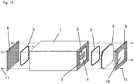
- FIG. 15 is an exploded perspective view of such a gas laser resonator.
- a square discharge chamber 2 is formed extending from one end to the other end of the tube 1.
- a pair of facing electrodes 3 and 4 is arranged inside the discharge chamber 2.
- a bracket 6 is attached to one end of the tube 1 with a gasket 5 interposed for sealing, and a glass plate 8 and another bracket 9 are attached to the other end with another gasket 7 interposed for sealing.
- On the end faces of the tube 1 to which the gaskets 5 and 7 are contact are formed grooves in which the gaskets 5 and 7 are seated, as well known in this field.
- the discharge chamber 2 is sealed hermetically with a laser medium gas at a pressure of one-tenth of the atmospheric pressure, for example, as usually used in the discharge.
- the laser generated in the discharge chamber 2 is emitted through the glass plate 8 and emerged out of a window 10 provided in the bracket 9.
- Elements 11 are screws used for fixing the brackets 6 and 9 to the tube 1.
- the gas laser resonator disclosed in US 5,237,580 A ( FIG. 1 ) has the structure as shown in FIG. 15 , and no consideration has been made to the problems of the change of the pressure in the discharge chamber and the inflow of impurity gases, caused by leakage of air or the like into the discharge chamber.
- US 5,237,580 A discloses a gas laser resonator having a tube including a discharge chamber for lasing, and a first sealing member is provided at each end of said tube to seal said discharge chamber only.
- US 2005/083984 A1 discloses a gas laser resonator comprising a tube including a discharge chamber for lasing. First and second sealing members are provided at an end of the tube for sealing the discharge chamber. Between the sealing members a buffer chamber is located. The discharge chamber and the buffer chamber are sealed so that a pressure difference between the chambers can be obtained. The buffer chamber is used to avoid leakage towards a discharge chamber.
- the purpose of the present invention is to prevent, in the gas laser resonator, the deterioration in quality of discharge by reducing the change of the pressure in the discharge chamber and the inflow of the impurity gases, caused by leakage of air or the like into the discharge chamber.
- the gas laser resonator according to the present invention can reduce the change of the pressure in the discharge chamber and the inflow of the impurity gases, caused by leakage of air or the like into the discharge chamber, so that the deterioration in quality of discharge can be prevented. Therefore, when applied to the laser resonator for the laser machining apparatus that is used for the machining using the laser, for example, the present invention allows for the advantages of being able to enhance the quality of the laser machining, eliminating the need for the means for detecting or predicting the deterioration in quality of the laser medium gas, eliminating the need for the exchange operation of the laser medium gas for recovering the quality of the laser medium gas, and so on.
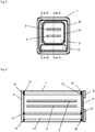
- FIG. 1 is an exploded perspective view of a gas laser resonator of the embodiment 1 of the present invention
- FIG. 2 is a transverse sectional view of a tube of FIG. 1
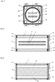
- FIG. 3 is a transverse sectional view of the right end sealing part of the tube of FIG. 1 when viewed inward through the glass plate side
- FIGS. 4 and 5 are sectional views along the lines A-A' and B-B' of FIG. 3 , respectively.
- FIGS. 1-5 the same elements as those in the conventional art of FIG. 15 are provided with the same reference numerals, and the differences from FIG. 15 are as follows. It is noted that, in FIGS. 4 and 5 , the screws 11 for fixing the brackets 6 and 9 to the tube 1 are omitted, and also omitted from subsequent drawings for simplicity.
- another rectangular chamber 12 (hereinafter referred to as the "buffer chamber 12") is provided under the discharge chamber 2 in parallel to the discharge chamber 2 extending from one end of the tube 1 to the other end, similar to the discharge chamber 2.
- the bracket 6 is attached to the end face of one end of the tube 1 interposing a gasket 13 only for sealing the opening of the discharge chamber 2 and a gasket 14 for sealing both openings of the discharge chamber 2 and the buffer chamber 12.
- a glass plate 8 and further the bracket 9 are attached to the end face of the other end of the tube 1 with a gasket 15 interposed only for sealing the opening of the discharge chamber 2 and a gasket 16 interposed for sealing both openings of the discharge chamber 2 and the buffer chamber 12.
- On the end faces of the tube 1 which the gaskets 13 to 16 contact are formed grooves in which the gaskets 13 to 16 are seated, similarly to the arrangement of FIG. 15 .
- the buffer chamber 12 communicates with an interstitial space between the gaskets 13 and 14 and another interstitial space between the gaskets 15 and 16 in FIG. 4 , and the way of communicating with the interstitial spaces from a longitudinal view is seen in FIG. 5 .
- the gaskets 13 and 15 are surrounded structurally by the buffer chamber 12 and the interstitial spaces communicating with it, and that spaces are sealed hermetically so that the pressure in those is lower than the pressure in the discharge chamber 2, specifically, it is a vacuum.
- the buffer chamber 12 is sealed only by the gasket 14 and the gasket 16, as seen from FIGS. 4 and 5 .
- the pressure difference across the gasket 14 or 16 is equal to the atmospheric pressure because the buffer chamber 12 is vacuum and the exterior is the atmospheric pressure
- the pressure difference across the gasket 13 or 15 is one-tenth of the atmospheric pressure that is significantly low, because the pressure in the discharge chamber 2 is a pressure of one-tenth of the atmospheric pressure and the buffer chamber 12 is vacuum. This results in the significant reduction of the leakage through the gaskets 13 and 15 that only seal the openings of the discharge chamber 2, which can significantly reduce the change of pressure in the discharge chamber 2.
- the difference between the pressures in the discharge chamber 2 and the buffer chamber 12 can be reduced, so that the inflow from the buffer chamber 12 to the discharge chamber 2 is decreased.
- the pressure change in the discharge chamber 2 after a certain period of time having elapsed is approximately obtained by multiplying the leak rate of the discharge chamber 2 by the elapsed time and then dividing it by the volume of the discharge chamber 2.
- the leak rate indicates the performance of the hermetical sealing and is proportional to the pressure difference. The same consideration is also applied to the buffer chamber 12.
- the volume of the discharge chamber 2 is 1 m 3
- the volume of the buffer chamber 12 is 1/50 m 3
- the initial value of the laser medium gas pressure in the discharge chamber 2 is 0.1 atm, 1 atm being 101325 Pa
- the initial value of the gas pressure in the buffer chamber 12 is zero (vacuum)
- the leak rate of the discharge chamber 2 and the buffer chamber 12 is 0.001 m 3 ⁇ atm/year at a pressure difference of 1 atm.
- the discharge chamber 2 loses its function and reaches the end of its product life cycle when an inflow of the impurity gases (air or the like) causes a change of 1% of the pressure of the laser medium gas sealed in the discharge chamber 2, that is, 0.001 atm.
- the leak rate becomes 0.0009 m 3 ⁇ atm/year, which results in that after 1.11 years have elapsed, the inflow of the impurity gases to the discharge chamber 2 makes a change of 0.001 atm and thus the discharge chamber 2 loses its function and reaches its end-of-life. Therefore, the lifetime of the discharge chamber 2 of this conventional art is 1.11 years.
- the following is an approximate calculation of the lifetime. It is noted that, since the volume of the discharge chamber 2 is significantly larger than that of the buffer chamber 12, the change of the gas pressure in the discharge chamber 2 is smaller than that in the buffer chamber 12. Thus, it is assumed here for the sake of simple description that the gas pressure in the discharge chamber 2 does not change and is maintained at 0.1 atm.
- FIG. 14 is a graph showing a year-by-year changes of characteristic values in the embodiment 1.
- FIG. 14 indicates the pressure in the buffer chamber 12 and the sum of the partial pressures of impurity gases, such as air, in the discharge chamber 2, where it is assumed in each period that they change in a linear manner, for simplicity.
- the pressure in the buffer chamber 12 increases at a rate of 0.05 atm/year and reaches the pressure of 0.1 atm in two years. Until that time there is no inflow of the impurity gases, such as air, into the discharge chamber 2, since the pressure in the buffer chamber 12 is lower than the pressure in the discharge chamber 2, that is 0.1 atm, and the impurity gases have flown into the buffer chamber 12.
- the pressure of the buffer chamber 12 increases at a rate of 0.045 atm/year and reaches 0.2 atm in 2.2 years.
- the impurity gases such as air
- the leak rate into the discharge chamber 2 becomes 0.0001 m 3 ⁇ atm/year or less and therefore the inflow of the impurity gases (such as air) from the buffer chamber 12 causes a change of 0.00022 atm or less within the above-described period of 2.2 years in the discharge chamber 2.
- the change is only 0.022% or less of the laser medium gas. Up to here, 4.2 years in total have elapsed.
- the leak rate becomes 0.0008 m 3 ⁇ atm/year, and the volume of the buffer chamber 12 is 1/50 m 3 , so that the pressure of the buffer chamber 12 increases at a rate of 0.04 atm/year and reaches 0.3 atm in 2.5 years.
- the leak rate to the discharge chamber 2 is 0.0002 m 3 ⁇ atm/year or less and thus the flow of the impurity gases from the buffer chamber causes a change of 0.0005 atm or less in the discharge chamber 2 within 2.5 years.
- the impurity gases that can cause the change of 0.00072 atm or less in total has flown into the discharge chamber 2 from the buffer chamber 12 by this time, since the initial value of the laser medium gas pressure of the discharge chamber 2 is 0.1 atm, the inflow of the impurity gases is 0.72% or less of the laser medium gas. Up to here, 6.7 years in total have elapsed.
- the pressure change by the inflow of the impurity gases reaches 1% of the laser medium gas in the discharge chamber 2 in 1.11 years.
- the pressure change by the inflow of the impurity gases is still 0.72% or less of the laser medium gas even after 6.7 years elapse. Therefore, it can be understood that the life can be significantly improved.
- the buffer chamber 12 having a larger volume than 1/50 of the discharge chamber 2 results in a much longer lifetime. Therefore, in order to reduce the inflow of the impurity gases, such as air, into the discharge chamber 2 and the pressure change below 1% of the laser medium gas for about six years, which is necessary for the practical use, it is preferable that the pressure in the buffer chamber 12 is made vacuum and the volume of the buffer chamber 12 is set to 1/50 or greater than the volume of the discharge chamber 2, provided with a margin of safety.
- the volume of the buffer chamber 12 may be determined by the lifetime targeted and/or other various conditions into consideration.
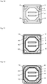
- FIGS. 6-9 are sectional views of the gas laser resonator of the embodiment 2 when viewed similarly to FIGS. 2-5 , respectively.
- FIGS. 6-9 the same elements as in FIGS. 1-5 are provided with the same numeral references.
- the differences from the embodiment 1 are as follows. While the discharge chamber 2 is shaped in a square in the embodiment 1, it is shaped in a circle here.
- This embodiment 2 consists of four buffer chambers 12.
- the buffer chambers 12 are formed in four corners in the periphery of the discharge chamber 2 in the tube 1 when viewed in the transverse sectional view of the tube 1, and each is shaped in a circle.
- the discharge chamber 2 is sealed by two gaskets 13 and 14 and two gaskets 15 and 16
- each opening of the four buffer chambers 12 is sealed by gasket 13 or gasket 15 only.
- the four buffer chambers 12 communicate with each other at the ends of the tube 1 and form one buffer chamber as a whole, which serves similarly to that in the embodiment 1.
- FIGS. 10 and 11 are transverse sectional views of the gas laser resonator of the embodiment 3 when viewed similarly to FIGS. 2 and 3 , respectively.
- FIG.S 10 and 11 the same elements as in FIGS. 1-5 are provided with the same numeral references.
- the difference from the embodiment 2 is that the discharge chamber 2 is shaped in an octagon and each buffer chamber 12 is shaped in a triangle.
- FIG. 12 is a transverse sectional view of the gas laser resonator of the embodiment 4 when viewed similarly to FIG. 3 .
- each buffer chamber 12 is shaped in a square.
- the discharge chamber 2 is shaped in a circle or an octagon and the buffer chambers 12 are arranged in four corners in the periphery of the discharge chamber 2 in the tube 1, so that the sectional area of the tube 1 can be effectively used allowing for a smaller external size of the tube 1 compared to the embodiment 1.
- the symmetrical entirety allows for a good mechanical balance and thus prevents a warp that would otherwise be caused by a thermal deformation, which results in a better stability as the gas laser resonator.
- Embodiment 5 not covered by the claims Next, the embodiment 5 describes an attachment part of a feed-through terminal of the gas laser resonator.
- FIG. 13 is a transverse sectional view of the attachment part of the feed-through terminal of the gas laser resonator of the embodiment 1 when viewed similarly to FIG. 2 , in which the same elements as in FIGS. 1-5 are provided with the same numeral references.
- a side of the tube 1 is formed with two through holes 21 and 22.
- the through hole 21 is connected to the discharge chamber 2, and the through hole 22 is connected to the buffer chamber 12.
- a insulating ceramics member 24 is inserted in the through hole 21 and is also inserted into a flange 23 in an airtight manner.
- conductive members 25 and 26 for electrically connecting electrodes 3 and 4 to the outside are inserted in an airtight manner.
- the flange 23 is attached to the side face of the tube 1 by a not-shown screw with a gasket 27 interposed only for sealing the opening of the discharge chamber 2 and a gasket 28 for sealing both openings of the discharge chamber 2 and the buffer chamber 12.
- the gaskets 27 and 28 are shaped in a square similarly to those in FIG. 1 or a circle, and their relationship is the same as the gaskets 13 and 14 or the gaskets 15 and 16 in FIG. 1 .
- the buffer chamber 12 is sealed by one gasket 28 only as seen from FIG. 13 .
- the pressure difference across the gasket 28 is equal to the atmospheric pressure, which is the difference between the pressure of the buffer chamber 12 and the atmospheric pressure of the exterior, whereas the pressure difference across the gasket 27 is one-tenth of the atmospheric pressure that is significantly low, because the difference between the pressures in the discharge chamber 2 and the buffer chamber 12 and is one-tenth of the atmospheric pressure. Therefore, this can significantly reduce the change of the pressure in the discharge chamber 2.
- the impurity gases such as air
- the reduced difference between the pressures in the discharge chamber 2 and the buffer chamber 12 can decrease the inflow from the buffer chamber 12 to the discharge chamber 2.
- the pressure in the buffer chamber 12 is set lower than that of the discharge chamber 2, such as set to a vacuum in the embodiments 1 to 5, the pressure in the buffer chamber 12 may be set higher than the atmospheric pressure.
- This causes no inflow of the impurity such as the atmosphere to the buffer chamber 12 and, as a result, allows for the decrease of the inflow of the impurity gases, such as air, into the discharge chamber 2.
- the gas or its component necessary for the discharge chamber 2 may be sealed in advance in the buffer chamber 12. This also allows for supplementing the gas or its component necessary for the discharge chamber 2 to the discharge chamber 2.
Landscapes
- Physics & Mathematics (AREA)
- Electromagnetism (AREA)
- Engineering & Computer Science (AREA)
- Plasma & Fusion (AREA)
- Optics & Photonics (AREA)
- Lasers (AREA)
Applications Claiming Priority (2)
| Application Number | Priority Date | Filing Date | Title |
|---|---|---|---|
| JP2013178087 | 2013-08-29 | ||
| JP2014138370A JP6407587B2 (ja) | 2013-08-29 | 2014-07-04 | ガスレーザ発振器 |
Publications (2)
| Publication Number | Publication Date |
|---|---|
| EP2869411A1 EP2869411A1 (en) | 2015-05-06 |
| EP2869411B1 true EP2869411B1 (en) | 2021-09-29 |
Family
ID=51392163
Family Applications (1)
| Application Number | Title | Priority Date | Filing Date |
|---|---|---|---|
| EP14182262.7A Active EP2869411B1 (en) | 2013-08-29 | 2014-08-26 | Gas laser resonator |
Country Status (3)
| Country | Link |
|---|---|
| US (1) | US9008143B2 (https=) |
| EP (1) | EP2869411B1 (https=) |
| JP (1) | JP6407587B2 (https=) |
Families Citing this family (1)
| Publication number | Priority date | Publication date | Assignee | Title |
|---|---|---|---|---|
| CN105896239A (zh) * | 2016-06-07 | 2016-08-24 | 清华大学深圳研究生院 | 一种射频co2激光器及其使用的平板电极、螺纹孔结构 |
Family Cites Families (12)
| Publication number | Priority date | Publication date | Assignee | Title |
|---|---|---|---|---|
| DE3729053A1 (de) * | 1987-08-31 | 1989-03-16 | Deutsche Forsch Luft Raumfahrt | Hochleistungs-bandleiterlaser |
| US5237580A (en) | 1990-10-12 | 1993-08-17 | Coherent, Inc. | RF excited CO2 slab waveguide laser |
| JPH0613679A (ja) * | 1992-03-31 | 1994-01-21 | Toshiba Corp | ガスレーザ発振器 |
| JPH09116237A (ja) * | 1995-10-16 | 1997-05-02 | Mitsubishi Electric Corp | 金属蒸気レーザ装置 |
| ATE226766T1 (de) * | 1995-11-27 | 2002-11-15 | Qsource Inc | Gaslaser mit rechteckigem entladungsraum |
| JPH10256625A (ja) * | 1997-03-06 | 1998-09-25 | Toshiba Corp | ガスレーザ装置 |
| JP4117694B2 (ja) * | 1998-01-19 | 2008-07-16 | 忠弘 大見 | エキシマレーザ発振装置及び露光装置 |
| US6567450B2 (en) * | 1999-12-10 | 2003-05-20 | Cymer, Inc. | Very narrow band, two chamber, high rep rate gas discharge laser system |
| US20050083984A1 (en) * | 2003-10-17 | 2005-04-21 | Igor Bragin | Laser system sealing |
| JP4270277B2 (ja) * | 2004-04-21 | 2009-05-27 | 三菱電機株式会社 | レーザ発振器およびレーザ加工機 |
| DE102007048617A1 (de) * | 2007-10-10 | 2009-04-16 | Robert Bosch Gmbh | Lasermodul |
| GB2478949A (en) * | 2010-03-24 | 2011-09-28 | Bosch Gmbh Robert | Over-pressure seal between Stirling engine and combustion chamber |
-
2014
- 2014-07-04 JP JP2014138370A patent/JP6407587B2/ja active Active
- 2014-08-26 EP EP14182262.7A patent/EP2869411B1/en active Active
- 2014-08-27 US US14/470,148 patent/US9008143B2/en active Active
Also Published As
| Publication number | Publication date |
|---|---|
| EP2869411A1 (en) | 2015-05-06 |
| JP6407587B2 (ja) | 2018-10-17 |
| JP2015065410A (ja) | 2015-04-09 |
| US9008143B2 (en) | 2015-04-14 |
| US20150063397A1 (en) | 2015-03-05 |
Similar Documents
| Publication | Publication Date | Title |
|---|---|---|
| EP2463891B1 (en) | Miniature mass spectrometer system | |
| US20120001648A1 (en) | Capacitance Sensors | |
| JP2012043672A (ja) | 質量分析装置 | |
| US11658019B2 (en) | IMR-MS reaction chamber | |
| JP6436236B2 (ja) | シャッター | |
| KR20100121678A (ko) | 가요성 하우징을 구비한 확산 냉각 이산화탄소 레이저 | |
| EP2869411B1 (en) | Gas laser resonator | |
| US10852207B2 (en) | Vacuum gauge | |
| US20140217280A1 (en) | Mass spectrometry device | |
| JP4029765B2 (ja) | プラズマ処理装置 | |
| KR101385047B1 (ko) | 고출력 엑시머 레이저 소스용 챔버 | |
| EP3724503B1 (en) | Pressure gradient pump | |
| TWI589911B (zh) | 內建至外殼設計之封閉壓力釋放機構 | |
| KR20160089895A (ko) | 샘플 홀더 및 관련 투과 장치 | |
| JP4335943B2 (ja) | 液体調整タンクとしてのマルチチャンバシステムとその使用方法 | |
| US9948054B2 (en) | Vacuum container of laser oscillator | |
| US2482770A (en) | Window for pressure chambers | |
| RU2580101C1 (ru) | Корпус генератора импульсных напряжений | |
| CN112585718B (zh) | 具有改进构造的检测器 | |
| CN120370653B (zh) | 气室、分子时钟以及气室平衡方法 | |
| WO2022094005A1 (en) | Microwave transmission window for high vacuum applications | |
| JP2023010480A (ja) | ゴム0-リングシールとバックアップリングシールとを一体化したあり溝適合超低ガス透過率複合シール | |
| JP7826874B2 (ja) | 配管接続機構 | |
| US4746317A (en) | Electron tube evacuating manifold system | |
| KR102887150B1 (ko) | 조립식 진공 챔버 |
Legal Events
| Date | Code | Title | Description |
|---|---|---|---|
| PUAI | Public reference made under article 153(3) epc to a published international application that has entered the european phase |
Free format text: ORIGINAL CODE: 0009012 |
|
| 17P | Request for examination filed |
Effective date: 20140826 |
|
| AK | Designated contracting states |
Kind code of ref document: A1 Designated state(s): AL AT BE BG CH CY CZ DE DK EE ES FI FR GB GR HR HU IE IS IT LI LT LU LV MC MK MT NL NO PL PT RO RS SE SI SK SM TR |
|
| AX | Request for extension of the european patent |
Extension state: BA ME |
|
| R17P | Request for examination filed (corrected) |
Effective date: 20151106 |
|
| RBV | Designated contracting states (corrected) |
Designated state(s): AL AT BE BG CH CY CZ DE DK EE ES FI FR GB GR HR HU IE IS IT LI LT LU LV MC MK MT NL NO PL PT RO RS SE SI SK SM TR |
|
| STAA | Information on the status of an ep patent application or granted ep patent |
Free format text: STATUS: EXAMINATION IS IN PROGRESS |
|
| 17Q | First examination report despatched |
Effective date: 20180104 |
|
| REG | Reference to a national code |
Ref country code: DE Ref legal event code: R079 Ref document number: 602014080346 Country of ref document: DE Free format text: PREVIOUS MAIN CLASS: H01S0003036000 Ipc: H01S0003034000 |
|
| GRAP | Despatch of communication of intention to grant a patent |
Free format text: ORIGINAL CODE: EPIDOSNIGR1 |
|
| STAA | Information on the status of an ep patent application or granted ep patent |
Free format text: STATUS: GRANT OF PATENT IS INTENDED |
|
| RIC1 | Information provided on ipc code assigned before grant |
Ipc: H01S 3/03 20060101ALI20200909BHEP Ipc: H01S 3/034 20060101AFI20200909BHEP Ipc: H01S 3/036 20060101ALI20200909BHEP |
|
| INTG | Intention to grant announced |
Effective date: 20200921 |
|
| GRAJ | Information related to disapproval of communication of intention to grant by the applicant or resumption of examination proceedings by the epo deleted |
Free format text: ORIGINAL CODE: EPIDOSDIGR1 |
|
| STAA | Information on the status of an ep patent application or granted ep patent |
Free format text: STATUS: EXAMINATION IS IN PROGRESS |
|
| INTC | Intention to grant announced (deleted) | ||
| GRAP | Despatch of communication of intention to grant a patent |
Free format text: ORIGINAL CODE: EPIDOSNIGR1 |
|
| STAA | Information on the status of an ep patent application or granted ep patent |
Free format text: STATUS: GRANT OF PATENT IS INTENDED |
|
| INTG | Intention to grant announced |
Effective date: 20210406 |
|
| GRAS | Grant fee paid |
Free format text: ORIGINAL CODE: EPIDOSNIGR3 |
|
| GRAA | (expected) grant |
Free format text: ORIGINAL CODE: 0009210 |
|
| STAA | Information on the status of an ep patent application or granted ep patent |
Free format text: STATUS: THE PATENT HAS BEEN GRANTED |
|
| AK | Designated contracting states |
Kind code of ref document: B1 Designated state(s): AL AT BE BG CH CY CZ DE DK EE ES FI FR GB GR HR HU IE IS IT LI LT LU LV MC MK MT NL NO PL PT RO RS SE SI SK SM TR |
|
| REG | Reference to a national code |
Ref country code: GB Ref legal event code: FG4D |
|
| REG | Reference to a national code |
Ref country code: DE Ref legal event code: R096 Ref document number: 602014080346 Country of ref document: DE |
|
| REG | Reference to a national code |
Ref country code: CH Ref legal event code: EP Ref country code: AT Ref legal event code: REF Ref document number: 1435035 Country of ref document: AT Kind code of ref document: T Effective date: 20211015 |
|
| REG | Reference to a national code |
Ref country code: IE Ref legal event code: FG4D |
|
| REG | Reference to a national code |
Ref country code: LT Ref legal event code: MG9D |
|
| PG25 | Lapsed in a contracting state [announced via postgrant information from national office to epo] |
Ref country code: HR Free format text: LAPSE BECAUSE OF FAILURE TO SUBMIT A TRANSLATION OF THE DESCRIPTION OR TO PAY THE FEE WITHIN THE PRESCRIBED TIME-LIMIT Effective date: 20210929 Ref country code: RS Free format text: LAPSE BECAUSE OF FAILURE TO SUBMIT A TRANSLATION OF THE DESCRIPTION OR TO PAY THE FEE WITHIN THE PRESCRIBED TIME-LIMIT Effective date: 20210929 Ref country code: SE Free format text: LAPSE BECAUSE OF FAILURE TO SUBMIT A TRANSLATION OF THE DESCRIPTION OR TO PAY THE FEE WITHIN THE PRESCRIBED TIME-LIMIT Effective date: 20210929 Ref country code: NO Free format text: LAPSE BECAUSE OF FAILURE TO SUBMIT A TRANSLATION OF THE DESCRIPTION OR TO PAY THE FEE WITHIN THE PRESCRIBED TIME-LIMIT Effective date: 20211229 Ref country code: FI Free format text: LAPSE BECAUSE OF FAILURE TO SUBMIT A TRANSLATION OF THE DESCRIPTION OR TO PAY THE FEE WITHIN THE PRESCRIBED TIME-LIMIT Effective date: 20210929 Ref country code: LT Free format text: LAPSE BECAUSE OF FAILURE TO SUBMIT A TRANSLATION OF THE DESCRIPTION OR TO PAY THE FEE WITHIN THE PRESCRIBED TIME-LIMIT Effective date: 20210929 Ref country code: BG Free format text: LAPSE BECAUSE OF FAILURE TO SUBMIT A TRANSLATION OF THE DESCRIPTION OR TO PAY THE FEE WITHIN THE PRESCRIBED TIME-LIMIT Effective date: 20211229 |
|
| REG | Reference to a national code |
Ref country code: NL Ref legal event code: MP Effective date: 20210929 |
|
| REG | Reference to a national code |
Ref country code: AT Ref legal event code: MK05 Ref document number: 1435035 Country of ref document: AT Kind code of ref document: T Effective date: 20210929 |
|
| PG25 | Lapsed in a contracting state [announced via postgrant information from national office to epo] |
Ref country code: LV Free format text: LAPSE BECAUSE OF FAILURE TO SUBMIT A TRANSLATION OF THE DESCRIPTION OR TO PAY THE FEE WITHIN THE PRESCRIBED TIME-LIMIT Effective date: 20210929 Ref country code: GR Free format text: LAPSE BECAUSE OF FAILURE TO SUBMIT A TRANSLATION OF THE DESCRIPTION OR TO PAY THE FEE WITHIN THE PRESCRIBED TIME-LIMIT Effective date: 20211230 |
|
| PG25 | Lapsed in a contracting state [announced via postgrant information from national office to epo] |
Ref country code: AT Free format text: LAPSE BECAUSE OF FAILURE TO SUBMIT A TRANSLATION OF THE DESCRIPTION OR TO PAY THE FEE WITHIN THE PRESCRIBED TIME-LIMIT Effective date: 20210929 |
|
| PG25 | Lapsed in a contracting state [announced via postgrant information from national office to epo] |
Ref country code: IS Free format text: LAPSE BECAUSE OF FAILURE TO SUBMIT A TRANSLATION OF THE DESCRIPTION OR TO PAY THE FEE WITHIN THE PRESCRIBED TIME-LIMIT Effective date: 20220129 Ref country code: SK Free format text: LAPSE BECAUSE OF FAILURE TO SUBMIT A TRANSLATION OF THE DESCRIPTION OR TO PAY THE FEE WITHIN THE PRESCRIBED TIME-LIMIT Effective date: 20210929 Ref country code: RO Free format text: LAPSE BECAUSE OF FAILURE TO SUBMIT A TRANSLATION OF THE DESCRIPTION OR TO PAY THE FEE WITHIN THE PRESCRIBED TIME-LIMIT Effective date: 20210929 Ref country code: PT Free format text: LAPSE BECAUSE OF FAILURE TO SUBMIT A TRANSLATION OF THE DESCRIPTION OR TO PAY THE FEE WITHIN THE PRESCRIBED TIME-LIMIT Effective date: 20220131 Ref country code: PL Free format text: LAPSE BECAUSE OF FAILURE TO SUBMIT A TRANSLATION OF THE DESCRIPTION OR TO PAY THE FEE WITHIN THE PRESCRIBED TIME-LIMIT Effective date: 20210929 Ref country code: NL Free format text: LAPSE BECAUSE OF FAILURE TO SUBMIT A TRANSLATION OF THE DESCRIPTION OR TO PAY THE FEE WITHIN THE PRESCRIBED TIME-LIMIT Effective date: 20210929 Ref country code: ES Free format text: LAPSE BECAUSE OF FAILURE TO SUBMIT A TRANSLATION OF THE DESCRIPTION OR TO PAY THE FEE WITHIN THE PRESCRIBED TIME-LIMIT Effective date: 20210929 Ref country code: EE Free format text: LAPSE BECAUSE OF FAILURE TO SUBMIT A TRANSLATION OF THE DESCRIPTION OR TO PAY THE FEE WITHIN THE PRESCRIBED TIME-LIMIT Effective date: 20210929 Ref country code: CZ Free format text: LAPSE BECAUSE OF FAILURE TO SUBMIT A TRANSLATION OF THE DESCRIPTION OR TO PAY THE FEE WITHIN THE PRESCRIBED TIME-LIMIT Effective date: 20210929 Ref country code: AL Free format text: LAPSE BECAUSE OF FAILURE TO SUBMIT A TRANSLATION OF THE DESCRIPTION OR TO PAY THE FEE WITHIN THE PRESCRIBED TIME-LIMIT Effective date: 20210929 |
|
| REG | Reference to a national code |
Ref country code: DE Ref legal event code: R097 Ref document number: 602014080346 Country of ref document: DE |
|
| PG25 | Lapsed in a contracting state [announced via postgrant information from national office to epo] |
Ref country code: DK Free format text: LAPSE BECAUSE OF FAILURE TO SUBMIT A TRANSLATION OF THE DESCRIPTION OR TO PAY THE FEE WITHIN THE PRESCRIBED TIME-LIMIT Effective date: 20210929 |
|
| PLBE | No opposition filed within time limit |
Free format text: ORIGINAL CODE: 0009261 |
|
| STAA | Information on the status of an ep patent application or granted ep patent |
Free format text: STATUS: NO OPPOSITION FILED WITHIN TIME LIMIT |
|
| 26N | No opposition filed |
Effective date: 20220630 |
|
| PG25 | Lapsed in a contracting state [announced via postgrant information from national office to epo] |
Ref country code: SI Free format text: LAPSE BECAUSE OF FAILURE TO SUBMIT A TRANSLATION OF THE DESCRIPTION OR TO PAY THE FEE WITHIN THE PRESCRIBED TIME-LIMIT Effective date: 20210929 |
|
| PG25 | Lapsed in a contracting state [announced via postgrant information from national office to epo] |
Ref country code: IT Free format text: LAPSE BECAUSE OF FAILURE TO SUBMIT A TRANSLATION OF THE DESCRIPTION OR TO PAY THE FEE WITHIN THE PRESCRIBED TIME-LIMIT Effective date: 20210929 |
|
| PG25 | Lapsed in a contracting state [announced via postgrant information from national office to epo] |
Ref country code: MC Free format text: LAPSE BECAUSE OF FAILURE TO SUBMIT A TRANSLATION OF THE DESCRIPTION OR TO PAY THE FEE WITHIN THE PRESCRIBED TIME-LIMIT Effective date: 20210929 |
|
| REG | Reference to a national code |
Ref country code: CH Ref legal event code: PL |
|
| PG25 | Lapsed in a contracting state [announced via postgrant information from national office to epo] |
Ref country code: LU Free format text: LAPSE BECAUSE OF NON-PAYMENT OF DUE FEES Effective date: 20220826 Ref country code: LI Free format text: LAPSE BECAUSE OF NON-PAYMENT OF DUE FEES Effective date: 20220831 Ref country code: CH Free format text: LAPSE BECAUSE OF NON-PAYMENT OF DUE FEES Effective date: 20220831 |
|
| REG | Reference to a national code |
Ref country code: BE Ref legal event code: MM Effective date: 20220831 |
|
| PG25 | Lapsed in a contracting state [announced via postgrant information from national office to epo] |
Ref country code: IE Free format text: LAPSE BECAUSE OF NON-PAYMENT OF DUE FEES Effective date: 20220826 Ref country code: FR Free format text: LAPSE BECAUSE OF NON-PAYMENT OF DUE FEES Effective date: 20220831 |
|
| PG25 | Lapsed in a contracting state [announced via postgrant information from national office to epo] |
Ref country code: BE Free format text: LAPSE BECAUSE OF NON-PAYMENT OF DUE FEES Effective date: 20220831 |
|
| PG25 | Lapsed in a contracting state [announced via postgrant information from national office to epo] |
Ref country code: HU Free format text: LAPSE BECAUSE OF FAILURE TO SUBMIT A TRANSLATION OF THE DESCRIPTION OR TO PAY THE FEE WITHIN THE PRESCRIBED TIME-LIMIT; INVALID AB INITIO Effective date: 20140826 |
|
| PG25 | Lapsed in a contracting state [announced via postgrant information from national office to epo] |
Ref country code: SM Free format text: LAPSE BECAUSE OF FAILURE TO SUBMIT A TRANSLATION OF THE DESCRIPTION OR TO PAY THE FEE WITHIN THE PRESCRIBED TIME-LIMIT Effective date: 20210929 Ref country code: CY Free format text: LAPSE BECAUSE OF FAILURE TO SUBMIT A TRANSLATION OF THE DESCRIPTION OR TO PAY THE FEE WITHIN THE PRESCRIBED TIME-LIMIT Effective date: 20210929 |
|
| PG25 | Lapsed in a contracting state [announced via postgrant information from national office to epo] |
Ref country code: MK Free format text: LAPSE BECAUSE OF FAILURE TO SUBMIT A TRANSLATION OF THE DESCRIPTION OR TO PAY THE FEE WITHIN THE PRESCRIBED TIME-LIMIT Effective date: 20210929 |
|
| PG25 | Lapsed in a contracting state [announced via postgrant information from national office to epo] |
Ref country code: MT Free format text: LAPSE BECAUSE OF FAILURE TO SUBMIT A TRANSLATION OF THE DESCRIPTION OR TO PAY THE FEE WITHIN THE PRESCRIBED TIME-LIMIT Effective date: 20210929 |
|
| PGFP | Annual fee paid to national office [announced via postgrant information from national office to epo] |
Ref country code: DE Payment date: 20250702 Year of fee payment: 12 |
|
| PGFP | Annual fee paid to national office [announced via postgrant information from national office to epo] |
Ref country code: GB Payment date: 20250703 Year of fee payment: 12 |
|
| PG25 | Lapsed in a contracting state [announced via postgrant information from national office to epo] |
Ref country code: TR Free format text: LAPSE BECAUSE OF FAILURE TO SUBMIT A TRANSLATION OF THE DESCRIPTION OR TO PAY THE FEE WITHIN THE PRESCRIBED TIME-LIMIT Effective date: 20210929 |