EP2869324B1 - Herzförmige nockenscheibe und schalter damit - Google Patents
Herzförmige nockenscheibe und schalter damit Download PDFInfo
- Publication number
- EP2869324B1 EP2869324B1 EP13809472.7A EP13809472A EP2869324B1 EP 2869324 B1 EP2869324 B1 EP 2869324B1 EP 13809472 A EP13809472 A EP 13809472A EP 2869324 B1 EP2869324 B1 EP 2869324B1
- Authority
- EP
- European Patent Office
- Prior art keywords
- end part
- vertex
- heart
- cam
- sliding end
- Prior art date
- Legal status (The legal status is an assumption and is not a legal conclusion. Google has not performed a legal analysis and makes no representation as to the accuracy of the status listed.)
- Not-in-force
Links
Images





Classifications
-
- H—ELECTRICITY
- H01—ELECTRIC ELEMENTS
- H01H—ELECTRIC SWITCHES; RELAYS; SELECTORS; EMERGENCY PROTECTIVE DEVICES
- H01H13/00—Switches having rectilinearly-movable operating part or parts adapted for pushing or pulling in one direction only, e.g. push-button switch
- H01H13/50—Switches having rectilinearly-movable operating part or parts adapted for pushing or pulling in one direction only, e.g. push-button switch having a single operating member
- H01H13/56—Switches having rectilinearly-movable operating part or parts adapted for pushing or pulling in one direction only, e.g. push-button switch having a single operating member the contact returning to its original state upon the next application of operating force
- H01H13/562—Switches having rectilinearly-movable operating part or parts adapted for pushing or pulling in one direction only, e.g. push-button switch having a single operating member the contact returning to its original state upon the next application of operating force making use of a heart shaped cam
-
- H—ELECTRICITY
- H01—ELECTRIC ELEMENTS
- H01H—ELECTRIC SWITCHES; RELAYS; SELECTORS; EMERGENCY PROTECTIVE DEVICES
- H01H13/00—Switches having rectilinearly-movable operating part or parts adapted for pushing or pulling in one direction only, e.g. push-button switch
- H01H13/02—Details
- H01H13/26—Snap-action arrangements depending upon deformation of elastic members
-
- H—ELECTRICITY
- H01—ELECTRIC ELEMENTS
- H01H—ELECTRIC SWITCHES; RELAYS; SELECTORS; EMERGENCY PROTECTIVE DEVICES
- H01H3/00—Mechanisms for operating contacts
- H01H3/32—Driving mechanisms, i.e. for transmitting driving force to the contacts
- H01H3/42—Driving mechanisms, i.e. for transmitting driving force to the contacts using cam or eccentric
-
- H—ELECTRICITY
- H01—ELECTRIC ELEMENTS
- H01H—ELECTRIC SWITCHES; RELAYS; SELECTORS; EMERGENCY PROTECTIVE DEVICES
- H01H5/00—Snap-action arrangements, i.e. in which during a single opening operation or a single closing operation energy is first stored and then released to produce or assist the contact movement
- H01H5/04—Energy stored by deformation of elastic members
- H01H5/14—Energy stored by deformation of elastic members by twisting of torsion members
-
- H—ELECTRICITY
- H01—ELECTRIC ELEMENTS
- H01H—ELECTRIC SWITCHES; RELAYS; SELECTORS; EMERGENCY PROTECTIVE DEVICES
- H01H13/00—Switches having rectilinearly-movable operating part or parts adapted for pushing or pulling in one direction only, e.g. push-button switch
- H01H13/02—Details
- H01H13/26—Snap-action arrangements depending upon deformation of elastic members
- H01H13/28—Snap-action arrangements depending upon deformation of elastic members using compression or extension of coil springs
- H01H13/30—Snap-action arrangements depending upon deformation of elastic members using compression or extension of coil springs one end of spring transmitting movement to the contact member when the other end is moved by the operating part
Definitions
- the present invention relates to a heart cam mechanism and a switch including the heart cam mechanism.
- a switch which has a contact point that can be opened/closed by a pressing operation, includes a lock pin for maintaining a closed state of the switch.
- a cam-groove structure having a heart cam shape has been used as a cam-groove structure for sliding an end part of a lock pin.
- a cam-groove structure having a heart cam shape is disclosed in, for example, Patent Literature 1.
- This type of cam-groove structure includes (i) a locking section for locking an end part of a lock pin and (ii) a cam groove surrounding an outer periphery of the locking section. While a closed state of a switch is maintained, the end part of the lock pin is locked by the locking section. An open/close mechanism of the switch is made possible by causing the cam groove to slide the end part of the lock pin in a fixed direction (not to slide the end part in a reverse direction).
- Fig. 11 is a plan view illustrating the cam-groove structure disclosed in Patent Literature 1.
- respective depths of following three regions with respect to a lock pin in a cam groove 102 are set to be equal: (i) a free region 107, (ii) a locking region 108, and (iii) a particular flat path region in a guiding return path extending from the locking region 108 to the free region 107.
- an end part of the lock pin is prevented from moving in a reverse direction by (i) causing the end part of the lock pin to be in contact with a bottom surface of a cam groove by use of a pressing spring member and (ii) configuring the bottom surface of the cam groove to have a step-like form.
- a heart cam mechanism comprising the features of the preamble of claim 1 is known from US 4 956 529 A .
- the present invention has been made in view of the problem, and it is an object of the present invention to provide a heart cam mechanism and a switch including the heart cam mechanism, which realize a highly reliable switch open/close mechanism by preventing an end part of a lock pin from moving in a reverse direction even in a case where a step-like part of a bottom surface of a cam groove is worn out.
- a heart cam mechanism includes: a cam groove including a heart cam and surrounding cams; and a lock pin (i) having one end part which is fixed and (ii) the other end part which is a sliding end part that slides while pushing against a bottom surface of the cam groove, the heart cam having a concave part for engaging with the sliding end part and releasing the engaging so as to switch between a locked state and an unlocked state of a switch whose contact point is opened or closed by a pressing operation, the sliding end part being configured to engage with the concave part at a locking position, the sliding end part being configured to simultaneously (i) make reciprocating motion in a pressing-operation direction in which the pressing operation is carried out and (ii) move, in the cam groove located outside the heart cam, along a heart-shaped path which is depressed at the locking position, the heart-shaped path having a first position which is a vertex position opposite the locking position and having a second position and a third position which are two vertex positions on a locking-position side, the sliding end
- the heart cam mechanism of the present invention is configured such that the sliding end part being configured to engage with the concave part at a locking position, during a pressing operation, the sliding end part being configured to move, in the cam groove located outside the heart cam, along a heart-shaped path which is depressed at the locking position, the heart-shaped path having a first position which is a vertex position opposite the locking position and having a second position and a third position which are two vertex positions on a locking-position side, the sliding end part being configured to pass through the first position, the second position, the locking position, and the third position in this order, the heart cam having a first vertex, a second vertex, and a third vertex corresponding to the first position, the second position, and the third position of the heart-shaped path, respectively, a surrounding cam, which faces the concave part, having a locking position guiding point for guiding the sliding end part from the second position to the locking position, and the heart cam and the surrounding cams being provided such that, while the sliding part is located at each one
- a switch of the present invention includes: a pressing part by which a pressing operation is carried out to open or close a circuit; the above-described heart cam mechanism; and a base that fixes the one end part of the lock pin.
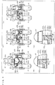
- Fig. 1 is a set of views (a) and (b), illustrating a configuration which is a prerequisite for the present switch (switch equipped with a reset function).
- (a) of Fig. 1 is a perspective view illustrating an external appearance
- (b) of Fig. 1 is a perspective view illustrating an internal configuration.
- Fig. 2 is an exploded perspective view of the switch.
- Fig. 3 is a set of views (a) and (b), illustrating a configuration of a base 10 with which a plunger section 30' and a contact point mechanism 20 are combined.
- (a) of Fig. 3 is a perspective view illustrating a configuration of the plunger section 30'
- (b) of Fig. 3 is a perspective view illustrating the configuration of the base 10 with which the contact point mechanisms 20 are combined.
- the present switch is that of a push type, and has such a prerequisite configuration as including (i) the base 10 which is rectangular-shaped, (ii) two pairs of contact point mechanisms 20 combined with the base 10, (iii) the plunger section 30', (iv) a lock pin 40, and (v) a housing 50.
- the housing 50 is to be coupled with the base 10 so as to cover the contact point mechanisms 20 as well as supports the plunger section 30 such that the plunger section 30' can move vertically.
- one side part of the rectangular shape of the base 10 is provided with a pair of walls 11 ⁇ 11.
- the other side part is provided with a pair of walls 12 ⁇ 12 such that the pair of walls 12 ⁇ 12 face the walls 11 ⁇ 11.
- the base 10 also includes a dividing wall 13 which stands on a center part of a top surface of the base 10.
- the dividing wall 13 extends in a direction from the walls 11 to the walls 12. In the vicinity of an end part on a walls-side-12 side of the dividing wall 13, an engaging groove 14 is provided.
- the contact point mechanism 20 includes (i) supporting terminals 21, (ii) fixing contact point terminals 22, and (iii) movable contact segments 23.
- the supporting terminals 21 are each configured by an electrically conductive material which is bent so as to have an L-shaped cross section. One end part of each of the supporting terminals 21 is provided with a rising piece 21 a that rises upwards. A rotation bearing part 21b is provided so as to notch an edge part of the rising piece 21 a.
- the supporting terminals 21 are combined with the base 10 such that press-fitting tongues 21c protruding downwards from the respective supporting terminals 21 are press-fitted into corresponding press-fitting openings 15 of the base 10.
- the fixing contact point terminals 22 are each bent so as to have a substantially L-shaped cross-section.
- a fixing contact point 22a is provided at one end part of each of the fixing contact point terminals 22.
- the fixing contact point terminals 22 are combined with the base 10 such that press-fitting tongues 22b protruding downwards from the respective fixing contact point terminals 22 are press-fitted into corresponding press-fitting openings 15 of the base 10.
- the movable contact segments 23 are each configured by an electrically conductive material which is bent so as to have a substantially J-shaped cross section. One end part of each of the movable contact segments 23 is provided with a movable contact point 23a. An apical surface of the other end part, a sliding notched groove 23b is provided.
- the movable contact segments 23 are rotatably supported by causing respective narrow parts 23c, each of which is formed by notching both lateral end parts of the movable contact segment 23, to engage with corresponding rotation bearing part 21b of the respective supporting terminals 21.
- the plunger section 30' includes a plunger main body (pressing part) 31' and coil springs 32 ⁇ 32.
- the plunger main body 31' has a form that can be accommodated between the walls 11 and the walls 12 which face each other on the base 10.
- An operation part 31A which is intended for pressing operation, is provided so as to protrude from a center part of a top surface of the form.
- respective shank parts 31B are provided so as to have point symmetry therebetween.
- Coil springs 32 ⁇ 32 are inserted into sides of the plunger main body 31' and supported by the shank parts 31B.
- the plunger main body 31' also includes, on a lateral surface thereof, a cam groove 31C'.
- the cam groove 31C' is included to lock the plunger main body 31' at a predetermined position via the lock pin 40.
- the plunger main body 31' also includes, on a bottom surface thereof, pressing convex parts 31 D which protrudes parallel to the shank parts 31B.
- the coil springs 32 are each inserted into a corresponding one of the shank parts 31B while both end parts 32a and 32b of the coil spring 32 are inwardly flexed. This (i) causes the end parts 32a of the respective coil springs 32 to apply pressure against and to be in contact with corresponding ceiling surfaces 31 E of the plunger main body 31 and (ii) causes the end parts 32b of the respective coil springs 32 to apply pressure against and to be in contact with corresponding edge parts 31F of the plunger main body 31.
- the lock pin 40 has an upper end part 40a (sliding end part) and a lower end part 40b which are formed by bending both end parts of a rod-shaped metal material in reverse directions.
- the housing 50 has a box-like form that can be coupled with an outer periphery of the base 10 with which the contact point mechanism 20, the plunger section 30', and the lock pin 40 are being combined.
- an annular rib 52 is provided, the annular rib 52 forming an operation opening 51 into which the operation part 31A of the plunger main body 31' is to be inserted.
- position restricting convex parts 53 which restrict positions of the respective movable contact segments 23, are provided.
- spring force of the coil springs 32 causes the end parts 32a to be energized upwards. This causes the plunger main body 31' to be pulled upwards.
- the spring force of the coil springs 32 causes force that pulls the end parts 32b of the coil springs 32 downwards. This causes the end parts 32b of the coil springs 32 to push down the other end parts of the movable contact segments 23 (i.e. ends parts opposites the respective movable contact points 23a).
- the position restricting convex parts 53 are provided on the inner surface of the housing 50 (see (b) of Fig. 1 ).
- the upper end part 40a of the lock pin 40 presses against the bottom surface of the cam groove 31 C' as well as slide so as to move from the initial region 31C 1 ' to a first inclined groove 31C 2 ' to a second inclined groove 31C 3 ' to a third inclined groove 31C 4 ' (see (d) of Fig. 5 ).
- the end parts 32a of the coil springs 32 exceed their respective predetermined positions by pressing in of the operation part 31A of the plunger main body 31', the end parts 32a energize the corresponding movable contact segments 23 to be pushed over.
- This causes the movable contact segments 23 to instantly rotate with the corresponding rotation bearing parts 21b of the supporting terminals 21 serving as supporting points, and therefore causes the movable contact point 23a to come into contact with the corresponding fixing contact points 22a (see (e) of Fig. 5 ).
- the coil springs 32 energize the corresponding movable contact segments 23 to be pushed over while pressing the plunger main body 31' upwards (see (a) of Fig. 8 ).
- the upper end part 40a passes through the fifth inclined groove 31C 6 ' and then sixth inclined groove 31C 7 ', and then returns to the second inclined groove 31C 3 ' (see (b) of Fig. 8 ).
- the plunger main body 31' automatically returns to an initial position, the end parts 32b of the coil springs 32 energize, from a predetermined position, corresponding the movable contact segments 23 to be pulled up.
- the movable contact segments 23 instantly rotate with the corresponding rotation bearing parts 21b serving as supporting points, so that the movable contact points 23a become separated from the corresponding fixing contact points 22a (see (c) of Fig. 8 ). Furthermore, when the movable contact segments 23 thus rotate, the one end parts of the movable contact segments 23 (end parts on the respective movable-contact-point-23 sides) (i) come into contact with the corresponding pressing convex parts 31 D of the plunger main body 31', (ii) come into contact with the corresponding position restricting convex parts 53 provided on the inner surface of the housing 50, and then (iii) become positionally restricted (see (d) of Fig. 8 ). Then, the upper end part 40a of the lock pin 40 returns to the initial region 31C 1 ' of the cam groove 31C' (see (e) of Fig. 8 ).
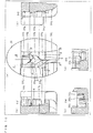
- FIG. 9 is a plan view illustrating a configuration of a plunger main body 31 which is a constituent member included in the heart cam mechanism of the present switch.
- a cam groove 31C includes a heart cam 1 and surrounding cams 2 through 5 that surround the heart cam 1.
- the heart cam 1 is heart-shaped and has a concave part 1d.
- the heart cam 1 has (i) a vertex 1a (first vertex) on a side opposite the concave part 1d and (ii) two vetices 1b ⁇ 1c (second and third vetices) on a concave-part-1d side.
- the surrounding cam 3, which faces the concave part 1d, has a convex part 3a (locking position guiding point).
- the upper end part 40a of the lock pin 40 is engaged with the concave part 1d of the heart cam 1, and is positioned at the locking position L. While the switch is pressed, the upper end part 40a slides while pushing against a bottom surface of the cam groove 31C located outside the heart cam 1, and moves along a heart-shaped path 6 which is depressed at the locking position L. Note that a vertex position opposite the locking position L of the heart-shaped path 6 is designated as a moving position 1A (first position). Then, two vertex positions on a locking-position-L side are designated as moving positions 1B ⁇ 1C (second and third positions).
- the upper end part 40a passes through the moving position 1A, the moving position 1B, the locking position L, and the moving position 1C in this order.
- the convex part 3a of the surrounding cam 3 serves as a locking position guiding point that guides the upper end part 40a from the moving position 1B to the locking position L.
- the heart-shaped path 6 is similar in shape to the heart cam 1. That is, the moving positions 1A through 1C of the heart-shaped path 6 correspond to the vertices 1a through 1c of the heart cam 1, respectively.
- the locking position L corresponds to the concave part 1d of the heart cam 1 (or the convex part 3a of the surrounding cam 3).
- a center part of the upper end part 40a of the lock pin 40 is shifted from the vertex 1a, the vertex 1b, the convex part 3a, and the vertex 1c, respectively.
- the upper end part 40a While the upper end part 40a is located at each one of the moving position 1A, the moving position 1B, and the locking position L, the upper end part 40a is shifted (i) from a corresponding one of reference lines of the vertex 1a, the vertex 1b, the convex part 3a, and the vertex 1c, respectively and (ii) toward part of the path where the upper end part 40a will move from said each one of the positions to a next position, given that the reference lines are respective lines extending in a pressing-operation direction from the vertex 1a, the vertex 1b, the convex part 3a, and the vertex 1c.
- the center part of the upper end part 40a at the moving position 1A is shifted (i) from the reference line extending in the pressing-operation direction from the vertex 1a of the heart cam 1 and (ii) toward part of the path where the upper end part 40a will move from the moving position 1A to the moving position 1B.
- the center part of the upper end part 40a at the moving position 1B is shifted (i) from the reference line extending in the pressing-operation direction from the vertex 1b of the heart cam 1 and (ii) toward part of the path where the upper end part 40a will move from the moving position 1B to the locking position L.
- the center part of the upper end part 40a at the locking position L is shifted (i) from the reference line extending in the pressing-operation direction from the convex part 3a of the surrounding cam 3 and (ii) toward part of the path where the upper end part 40a will move from the locking position L to the moving position 1C.
- the center part of the upper end part 40a at the moving position 1C is shifted (i) from the reference line extending in the pressing-operation direction from the vertex 1c of the heart cam 1 and (ii) toward part of the path where the upper end part 40a will move from the moving position 1C to the moving position 1A.
- the heart cam 1 and the surrounding cams 2 through 5 are provided so that the upper end part 40a is positioned as described above while located at each of the moving position 1A, the moving position 1B, the locking position L, and the moving position 1C. Therefore, while the upper end part 40a moves along the heart-shaped path 6 by passing through the positions, the corresponding vertices 1a through 1c of the heart cam 1 and the corresponding convex part 3a of the surrounding cam 3 serve as moving direction restricting sections for restricting moving directions of the upper end part 40a to respective directions in which the upper end part 40a should move to next positions.
- Fig. 10 illustrates a configuration of the bottom surface of the cam groove 31C.
- (a) of Fig. 10 is a top view.
- (b) of Fig. 10 is a cross-sectional view taken along the line F-F shown in (a) of Fig. 10 .
- (c) of Fig. 10 is a cross-sectional view taken along the line P-P shown in (a) of Fig. 10 .
- (d) of Fig. 10 is a cross-sectional view taken along the line H-H shown in (a) of Fig. 10 .
- (e) of Fig. 10 is a cross-sectional view taken along the line D-D shown in (a) of Fig. 10 .
- the cam groove 31C includes an initial region 31C 1 , a region 31C 2 , a first inclined groove 31C 3 , a second inclined groove 31C 4 , a flat groove 31C 5 , a locking region 31C 6 , a third inclined groove 31C 7 , and a fourth inclined groove 31C 8 .
- a pathway extending from the moving position 1A to the moving position 1B illustrated in Fig. 9 includes the initial region 31C 1 , the region 31C 2 , the first inclined groove 31C 3 , the second inclined groove 31C 4 , and the flat groove 31C 5 .
- a pathway (first pathway) extending from the moving position 1B to the locking position L includes the flat groove 31C 5 and the locking region 31C 6 .
- a pathway (second pathway) extending from the locking position L to the moving position 1C includes the locking region 31C 6 and the third inclined groove 31C 7 .
- a pathway (third pathway) extending from the moving position 1C to the moving position 1A includes the third inclined groove 31C 7 , the fourth inclined groove 31C 8 , and the initial region 31C 1 .
- respective bottom surfaces of the second inclined groove 31C 4 and of the flat groove 31C 5 as viewed from the cross section perpendicular to the pressing-operation direction (P-P cross section) are inclined downwards from the moving position 1B toward the moving position 1C in a pushing direction of the upper end part 40a. This prevents the upper end part 40a, which has left the moving position 1B and reached the locking position L (locking region 31C 6 ), from moving back toward the moving position 1B.
- the "pushing direction" of the upper end part 40a can be described as a direction in which the upper end part 40a extends from a bending part of the lock pin 40.
- a bottom surface of the third inclined groove 31C 7 as viewed from the cross section perpendicular to the pressing-operation direction (P-P cross section) is inclined downwards from the moving position 1B toward the moving position 1C in the pushing direction of the upper end part 40a. This prevents the upper end part 40a, which has left the locking position L (locking region 31C 6 ) and reached the moving position 1C, from moving back toward the locking position L.
- step B between the fourth inclined groove 31C 8 and initial region 31C 1 (corresponding the moving position 1A illustrated in Fig. 9 ) such that a bottom surface of the initial region 31C 1 drops from the fourth inclined groove 31C 8 toward the pushing direction.
- the step B is provided so as to extend in the pressing-operation direction from the vertex 1a of the heart cam 1. This causes the step B to prevent the upper end part 40a, which has passed through the step B and reached the initial region 31C 1 , from moving back toward the fourth inclined groove 31C 8 .
- the center part of the upper end part 40a located at the moving position 1A is reliably shifted (i) from the vertex 1a of the heart cam 1 and (ii) toward a direction where the upper end part 40a will move from the moving position 1A to the moving position 1B.
- the step B may be provided closer to the moving position 1A than is the vertex 1a of the heart cam 1.
- the fourth inclined groove 31C 8 On the pathway (third pathway) extending from the moving position 1C to the moving position 1A, the fourth inclined groove 31C 8 has a bottom surface that is inclined upwards from the moving position 1C toward the moving position 1A in a direction opposite the pushing direction. Then, an inclination starting position A of the bottom surface of the fourth inclined groove 31C 8 is located closer to the moving position 1A than is the vertex 1c of the heart cam 1. This prevents the upper end part 40a, which is moving from the moving position 1C to the moving position 1A, from moving to the locking position L. Furthermore, it is possible to sufficiently secure a difference in height between the bottom surface of the fourth inclined groove 31C 8 and the bottom surface of the initial region 31C 1 .
- Table 1 shows correspondence between (i) the regions of the cam groove provided in the plunger main body 31' illustrated in Figs. 5 through 8 and (ii) the respective regions of the cam groove provided in the plunger main body 31 illustrated in Fig. 10 .
- Cam groove of plunger main body 31' ( Figs. 5 through 8 ) Cam groove of plunger main body 31 ( Fig. 10 ) Initial region 31C 1 ' 31C 1 Region 31C 2 First inclined groove 31C 2 ' 31C 3 Second inclined groove 31C 3 ' 31C 4 Flat groove 31C 5 Locking region 31C 6 Third inclined groove 31C 4 ' 31C 7 Fourth inclined groove 31C 5 ' 31C 8 Fifth inclined groove 31C 6 ' Sixth inclined groove 31C 7 '
- a heart cam mechanism of the present invention includes: a cam groove including a heart cam and surrounding cams; and a lock pin (i) having one end part which is fixed and (ii) the other end part which is a sliding end part that slides while pushing against a bottom surface of the cam groove, the heart cam having a concave part for engaging with the sliding end part and releasing the engaging so as to switch between a locked state and an unlocked state of a switch whose contact point is opened or closed by a pressing operation, the sliding end part being configured to engage with the concave part at a locking position, the sliding end part being configured to simultaneously (i) make reciprocating motion in a pressing-operation direction in which the pressing operation is carried out and (ii) move, in the cam groove located outside the heart cam, along a heart-shaped path which is depressed at the locking position, the heart-shaped path having a first position which is a vertex position opposite the locking position and having a second position and a third position which are two vertex positions on a
- the heart cam and the surrounding cams being provided such that, while the sliding part is located at each one of the first position, the second position, the locking position, and the third position, a center part of the sliding end part is shifted from a corresponding one of reference lines toward part of the heart-shaped path where the sliding end part will move from said each one of the positions to a next position, the reference lines being respective lines extending in the pressing-operation direction from the first vertex, the second vertex, the locking position guiding point, and the third vertex.
- the members are arranged in relation to each other as follows:
- the center part of the sliding end part at the first position is shifted (i) from the reference line extending in the pressing-operation direction from the first vertex of the heart cam and (ii) toward part of the path where the sliding end part will move from the first position to the second position.
- the center part of the sliding end part at the second position is shifted (i) from the reference line extending in the pressing-operation direction from the second vertex of the heart cam and (ii) toward part of the path where the sliding end part will move from the second position to the locking position.
- the center part of the sliding end part at the locking position is shifted (i) from the reference line extending in the pressing-operation direction from the locking position guiding point of the surrounding cam and (ii) toward part of the path where the sliding end part will move from the locking position to the third position.
- the sliding end part at the third position is shifted (i) from the reference line extending in the pressing-operation direction from the first vertex of the heart cam and (ii) toward part of the path where the sliding end part will move from the third position to the first position.
- the heart cam and the surrounding cams are provided so that the sliding end part is positioned as described above while located at each of the first position, the second position, the locking position, and the third position. Therefore, according to the configuration, while the sliding end part moves along the heart-shaped path by passing through the positions, the corresponding first through third vertices of the heart cam and the corresponding locking position guiding point of the surrounding cam serve as moving direction restricting sections for restricting moving directions of the sliding end part to respective directions in which the sliding end part should move to next positions. This prevents the sliding end part from moving in a reverse direction, and therefore causes the sliding end part to smoothly move from each of the first position, the second position, the locking position, and the third position to a next one.
- the heart cam mechanism of the present invention is preferably configured such that, while a pathway extending from the second position to the locking position serves as a first pathway and a pathway extending from the locking position to the third position serves as a second pathway, respective bottom surfaces of the first pathway and of the second pathway as viewed from a cross section perpendicular to the pressing-operation direction are inclined downwards from the second position to the third position in a pushing direction of the sliding end part.
- the respective bottom surfaces of the first pathway and of the second pathway as viewed from a cross section perpendicular to the pressing-operation direction are inclined downwards from the second position to the third position in a pushing direction of the sliding end part. This prevents the sliding end part from moving in respective reverse directions when moving from the second position to the locking position and when moving from the locking position to the third position.
- the heart cam mechanism of the present invention is preferably configured such that: a third pathway extending from the third position to the first position has a step provided such that a bottom surface of a part of the cam groove, which part corresponds to the first position, drops toward the pushing direction of the sliding end part; and the step is provide so as to (i) extend in the pressing-operation direction from the first vertex of the heart cam or (ii) be located closer to the first position than is the first vertex.
- the step is thus provided so as to (i) extend in the pressing-operation direction from the first vertex of the heart cam or (ii) be located closer to the first position than is the first vertex. This causes the step to prevent the sliding end part, which has passed through the step and reached the first position, from moving back toward the third position. Therefore, the center part of the sliding end part located at the first position is reliably shifted (i) from the first vertex of the heart cam and (ii) toward a direction where the sliding end part will move from the first position to the second position.
- the heart cam mechanism of the present invention is preferably configured such that: the third pathway is provided with an inclined groove having a bottom surface inclined upwards from the third position to the first position in a direction opposite the pushing direction of the sliding end part; and the inclined groove has an inclination starting position which is located closer to the first position than is the third vertex of the heart cam.
- the third pathway is provided with an inclined groove having a bottom surface inclined upwards from the third position to the first position in a direction opposite the pushing direction of the sliding end part, and the inclined groove has an inclination starting position which is located closer to the first position than is the third vertex of the heart cam. This prevents the sliding end part, which is moving from the third position to the first position, from moving back to the locking position. Furthermore, it is possible to sufficiently secure a difference in height between (i) the bottom surface of the inclined groove and (ii) the bottom surface of part of the cam groove which part corresponds to the first position.
- a switch of the present invention includes: a pressing part by which the pressing operation is carried out to open or close a circuit; the above-described heart cam mechanism; and a base that fixes the one end part of the lock pin.
- the present invention can be used for electric appliances, such as washing machines and dish washers, which are capable of turning off a power switch in response to an external signal.
Landscapes
- Push-Button Switches (AREA)
Claims (4)
- Herzförmiger Nockenscheibenmechanismus, umfassend:eine Nockenscheibennut (31C) mit einer herzförmigen Nockenscheibe (1) und umgebenden Nockenscheiben (2, ..., 5), undeinen Verriegelungsstift (40), der (i) ein Endteil (40b), das ortsfest ist, und (ii) das andere Endteil (40a) aufweist, das ein gleitendes Endteil (40a) ist, das gleitet, während es gegen eine Bodenfläche der Nockenscheibennut (31C) drückt, wobeidie herzförmige Nockenscheibe (1) ein konkaves Teil (1d) zum Eingriff mit dem gleitenden Endteil (40a) und zur Aufhebung des Eingriffs aufweist, um so zwischen einem verriegelten Zustand und einem unverriegelten Zustand eines Schalters umzuschalten, dessen Kontaktstelle durch einen Drückvorgang geöffnet oder geschlossen wird,das gleitende Endteil (40a) zum Eingriff mit dem konkaven Teil (1d) an einer Verriegelungsposition (L) eingerichtet ist,das gleitende Endteil (40a) eingerichtet ist, gleichzeitig (i) eine Hin- und Her-Bewegung in Richtung des Drückvorgangs auszuführen, in der der Drückvorgang ausgeführt wird, und (ii) sich in der außerhalb der herzförmigen Nockenscheibe (1) befindlichen Nockenscheibennut (31C) entlang einer herzförmigen Bahn (6) zu bewegen, die an der Verriegelungsposition (L) vertieft ist,die herzförmige Bahn (6) eine erste Position (1A) aufweist, die eine der Verriegelungsposition abgewandte Scheitelpunktposition ist, und eine zweite Position (1B) und eine dritte Position (1C) aufweist,die zwei Scheitelpunktpositionen auf einer Verriegelungspositionsseite sind,das gleitende Endteil (40a) eingerichtet ist, die erste Position (1A), die zweite Position (1B), die Verriegelungsposition (L) und die dritte Position (1C) in dieser Reihenfolge zu durchlaufen,die herzförmige Nockenscheibe (1) einen ersten Scheitelpunkt (1a), einen zweiten Scheitelpunkt (1b) und einen dritten Scheitelpunkt (1c) entsprechend der der ersten Position (1A), der zweiten Position (1B) bzw. der dritten Position (1C) der herzförmigen Bahn (6) aufweist,eine umgebende Nockenscheibe (3), die dem konkaven Teil (1d) zugewandt ist und einen Verriegelungsposition-Führungspunkt (3a) zum Führen des gleitenden Endteils (40a) von der zweiten Position (1B) in die Verriegelungsposition (L) aufweist, unddie herzförmige Nockenscheibe (1) und die umgebenden Nockenscheiben (2, ..., 5) derart vorgesehen sind, dass, wenn das gleitende Endteil (40a) sich an einer jeweiligen der ersten Position (1A), der zweiten Position (1B), der Verriegelungsposition (L) und der dritten Position (1C) befindet, ein mittlerer Teil des gleitenden Endteils (40a) von einer entsprechenden von Bezugslinien zu einem Teil der herzförmigen Bahn (6) hin verschoben wird, wo das gleitende Endteil (40a) sich von der jeweiligen der Positionen (1A, 1B, 1C) zu einer nächsten Position bewegt, wobei die Bezugslinien jeweilige Linien sind, die sich in Richtung des Drückvorgangs von dem ersten Scheitelpunkt (1a), dem zweiten Scheitelpunkt (1b), dem Verriegelungsposition-Führungspunkt (3a) und dem dritten Scheitelpunkt (1c) erstrecken, dadurch gekennzeichnet, dass, während eine sich von der zweiten Position (1B) zu der Verriegelungsposition (L) erstreckende Bahn als eine erste Bahn (31C5, 31C6) dient, und eine sich von der Verriegelungsposition (L) zu der dritten Position (1C) erstreckende Bahn als eine zweite Bahn (31C6, 31C7) dient, jeweilige Bodenflächen der ersten Bahn (31C5, 31C6) und der zweiten Bahn (31C6, 31C7), gesehen aus einem Querschnitt senkrecht zu der Richtung des Drückvorgangs, von der zweiten Position (1B) zu der dritten Position (1C) in Drückrichtung des gleitenden Endteils (40a) nach unten geneigt sind.
- Herzförmiger Nockenscheibenmechanismus nach Anspruch 1, wobei:eine sich von der dritten Position (1C) zu der ersten Position (1A) erstreckende dritte Bahn (31C7, 31C8, 31C1) eine Stufe aufweist, die derart vorgesehen ist, dass eine Bodenfläche eines Teils der Nockenscheibennut (31C), wobei dieser Teil der ersten Position (1A) entspricht, in der Drückrichtung des gleitenden Endteils (40a) abfällt, unddie Stufe derart vorgesehen ist, dass sie (i) sich in Richtung des Drückvorgangs von dem ersten Scheitelpunkt (1a) der herzförmigen Nockenscheibe (1) erstreckt oder (ii) sich näher an der ersten Position (1A) als der erste Scheitelpunkt (1a) befindet.
- Herzförmiger Nockenscheibenmechanismus nach Anspruch 2, wobei:die dritte Bahn (31C7, 31C8, 31C1) mit einer geneigten Nut versehen ist, die eine von der dritten Position (1C) zu der ersten Position (1A) in einer Richtung entgegengesetzt zu der Drückrichtung des gleitenden Endteils (40a) nach oben geneigte Bodenfläche aufweist, unddie geneigte Nut eine Anfangsposition der Neigung aufweist, die sich näher an der ersten Position (1A) als der dritte Scheitelpunkt (1c) der herzförmigen Nockenscheibe (1) befindet.
- Schalter, umfassend:ein Drückteil, durch das der Drückvorgang ausgeführt wird, um einen Stromkreis zu öffnen oder zu schließen,einen herzförmigen Nockenscheibenmechanismus nach einem der Ansprüche 1 bis 3, undeine Basis (10), die das eine Endteil (40b) des Verriegelungsstifts (40) fixiert.
Applications Claiming Priority (2)
| Application Number | Priority Date | Filing Date | Title |
|---|---|---|---|
| JP2012147859A JP5962259B2 (ja) | 2012-06-29 | 2012-06-29 | ハートカム機構、およびそれを備えたスイッチ |
| PCT/JP2013/067314 WO2014002976A1 (ja) | 2012-06-29 | 2013-06-25 | ハートカム機構、およびそれを備えたスイッチ |
Publications (3)
| Publication Number | Publication Date |
|---|---|
| EP2869324A1 EP2869324A1 (de) | 2015-05-06 |
| EP2869324A4 EP2869324A4 (de) | 2016-04-06 |
| EP2869324B1 true EP2869324B1 (de) | 2017-04-12 |
Family
ID=49783122
Family Applications (1)
| Application Number | Title | Priority Date | Filing Date |
|---|---|---|---|
| EP13809472.7A Not-in-force EP2869324B1 (de) | 2012-06-29 | 2013-06-25 | Herzförmige nockenscheibe und schalter damit |
Country Status (5)
| Country | Link |
|---|---|
| US (1) | US9514901B2 (de) |
| EP (1) | EP2869324B1 (de) |
| JP (1) | JP5962259B2 (de) |
| CN (1) | CN104321845B (de) |
| WO (1) | WO2014002976A1 (de) |
Families Citing this family (9)
| Publication number | Priority date | Publication date | Assignee | Title |
|---|---|---|---|---|
| CN104658790B (zh) * | 2015-03-02 | 2017-11-03 | 惠州Tcl移动通信有限公司 | 一种按钮装置及电子设备 |
| KR101570193B1 (ko) * | 2015-03-16 | 2015-11-18 | 주식회사 마이크로필터 | 반복밀어줌에 의하여 승강되는 승강체의 정방향의 상승을 유도하는 락킹-언락킹구조체 |
| BR112019002411A2 (pt) * | 2016-08-09 | 2019-06-04 | Koninklijke Philips Nv | mecanismo de travamento, e dispositivo |
| DE102017114226B4 (de) | 2016-09-30 | 2020-06-04 | Defond Components Limited | Verriegelbarer schaltmechanismus zur verwendung in einer elektrischen vorrichtung |
| CN107170610A (zh) * | 2017-07-16 | 2017-09-15 | 沈新权 | 一种具有闭合锁定装置的直流电动工具扳机调速开关 |
| CN108767584B (zh) * | 2018-05-31 | 2020-06-23 | 安徽安为科技有限公司 | 一种车载显示终端用易插防震动数据接口 |
| CN109920675B (zh) * | 2019-03-12 | 2022-01-07 | 杭州英纬特科技有限公司 | 按钮开关的自锁结构以及采用这种结构的按钮开关 |
| CN110335774A (zh) * | 2019-06-28 | 2019-10-15 | 贵州振华华联电子有限公司 | 一种小型平面凸轮自锁式电源按钮开关 |
| CN114388288B (zh) * | 2021-12-30 | 2024-03-19 | 苏州中兴联精密工业有限公司 | 开关连接器 |
Family Cites Families (15)
| Publication number | Priority date | Publication date | Assignee | Title |
|---|---|---|---|---|
| JPS5042283U (de) * | 1973-08-16 | 1975-04-28 | ||
| JPS5232431B2 (de) | 1973-08-17 | 1977-08-22 | ||
| JPS5937600B2 (ja) | 1976-07-07 | 1984-09-11 | キヤノン株式会社 | 印刷配線用原板 |
| JPS5611702Y2 (de) * | 1976-07-01 | 1981-03-17 | ||
| JPS5515741U (de) * | 1978-07-18 | 1980-01-31 | ||
| JPS5515741A (en) | 1978-07-21 | 1980-02-04 | Sapporo Breweries Ltd | Preparation of antitumor substance |
| GB2051481A (en) * | 1979-06-22 | 1981-01-14 | Electronic Components Ltd | Electrical switch |
| JPS58163115A (ja) | 1982-03-19 | 1983-09-27 | ソニー株式会社 | スイツチ |
| JPH01119132U (de) | 1988-02-08 | 1989-08-11 | ||
| JP3202515B2 (ja) | 1995-01-06 | 2001-08-27 | 株式会社東海理化電機製作所 | プッシュロックスイッチ |
| JPH08227627A (ja) | 1995-02-21 | 1996-09-03 | T K R:Kk | 押釦スイッチ等のハート型カム溝 |
| JP3621238B2 (ja) * | 1997-08-19 | 2005-02-16 | アルプス電気株式会社 | プッシュスイッチ |
| JP4275017B2 (ja) * | 2004-07-01 | 2009-06-10 | アルプス電気株式会社 | スイッチ装置 |
| JP4179397B1 (ja) | 2007-07-04 | 2008-11-12 | オムロン株式会社 | スイッチ |
| JP5088264B2 (ja) * | 2008-08-05 | 2012-12-05 | オムロン株式会社 | スイッチ |
-
2012
- 2012-06-29 JP JP2012147859A patent/JP5962259B2/ja active Active
-
2013
- 2013-06-25 US US14/403,592 patent/US9514901B2/en active Active
- 2013-06-25 CN CN201380027850.4A patent/CN104321845B/zh active Active
- 2013-06-25 EP EP13809472.7A patent/EP2869324B1/de not_active Not-in-force
- 2013-06-25 WO PCT/JP2013/067314 patent/WO2014002976A1/ja not_active Ceased
Non-Patent Citations (1)
| Title |
|---|
| None * |
Also Published As
| Publication number | Publication date |
|---|---|
| JP2014011068A (ja) | 2014-01-20 |
| CN104321845A (zh) | 2015-01-28 |
| JP5962259B2 (ja) | 2016-08-03 |
| US20150107980A1 (en) | 2015-04-23 |
| EP2869324A4 (de) | 2016-04-06 |
| WO2014002976A1 (ja) | 2014-01-03 |
| EP2869324A1 (de) | 2015-05-06 |
| CN104321845B (zh) | 2017-07-21 |
| US9514901B2 (en) | 2016-12-06 |
Similar Documents
| Publication | Publication Date | Title |
|---|---|---|
| EP2869324B1 (de) | Herzförmige nockenscheibe und schalter damit | |
| US8134095B2 (en) | Switch having a movable contact piece with a J-shaped cross section | |
| EP3089276B1 (de) | Verbinder | |
| EP1837953A1 (de) | Kartenverbinder | |
| US9865967B2 (en) | Connector | |
| EP2012333B1 (de) | Schalter | |
| US20180019079A1 (en) | Push switch | |
| JP2017228442A (ja) | コネクタ | |
| US20110209971A1 (en) | Switch | |
| JP2013182874A (ja) | レバー式コネクタ | |
| US8251726B2 (en) | Electrical connector having a metal frame with locking portions movable in transverse direction for locking/unlocking a card | |
| JP2010218938A (ja) | スイッチカバー | |
| JP2012164504A (ja) | カード用コネクタ | |
| JP5846107B2 (ja) | レバー式コネクタ | |
| JPH10283876A (ja) | プッシュスイッチ | |
| JP2001093385A (ja) | スライドスイッチ | |
| JPH09237546A (ja) | スライド操作型スイッチ | |
| JP2001006488A (ja) | 多段式押しボタンスイッチ | |
| JP2003036947A (ja) | 半導体パッケージ用ソケット | |
| JP2013118059A (ja) | カム溝構造、およびそれを備えたスイッチ | |
| JPH10208584A (ja) | プッシュスイッチ | |
| JP2007258021A (ja) | プッシュスイッチ | |
| JP2015220049A (ja) | レバー式コネクタ |
Legal Events
| Date | Code | Title | Description |
|---|---|---|---|
| PUAI | Public reference made under article 153(3) epc to a published international application that has entered the european phase |
Free format text: ORIGINAL CODE: 0009012 |
|
| 17P | Request for examination filed |
Effective date: 20150119 |
|
| AK | Designated contracting states |
Kind code of ref document: A1 Designated state(s): AL AT BE BG CH CY CZ DE DK EE ES FI FR GB GR HR HU IE IS IT LI LT LU LV MC MK MT NL NO PL PT RO RS SE SI SK SM TR |
|
| AX | Request for extension of the european patent |
Extension state: BA ME |
|
| DAX | Request for extension of the european patent (deleted) | ||
| RA4 | Supplementary search report drawn up and despatched (corrected) |
Effective date: 20160309 |
|
| RIC1 | Information provided on ipc code assigned before grant |
Ipc: H01H 13/56 20060101ALI20160303BHEP Ipc: H01H 3/42 20060101AFI20160303BHEP |
|
| GRAP | Despatch of communication of intention to grant a patent |
Free format text: ORIGINAL CODE: EPIDOSNIGR1 |
|
| STAA | Information on the status of an ep patent application or granted ep patent |
Free format text: STATUS: GRANT OF PATENT IS INTENDED |
|
| INTG | Intention to grant announced |
Effective date: 20170127 |
|
| GRAS | Grant fee paid |
Free format text: ORIGINAL CODE: EPIDOSNIGR3 |
|
| GRAA | (expected) grant |
Free format text: ORIGINAL CODE: 0009210 |
|
| STAA | Information on the status of an ep patent application or granted ep patent |
Free format text: STATUS: THE PATENT HAS BEEN GRANTED |
|
| AK | Designated contracting states |
Kind code of ref document: B1 Designated state(s): AL AT BE BG CH CY CZ DE DK EE ES FI FR GB GR HR HU IE IS IT LI LT LU LV MC MK MT NL NO PL PT RO RS SE SI SK SM TR |
|
| REG | Reference to a national code |
Ref country code: GB Ref legal event code: FG4D |
|
| REG | Reference to a national code |
Ref country code: CH Ref legal event code: EP |
|
| REG | Reference to a national code |
Ref country code: IE Ref legal event code: FG4D |
|
| REG | Reference to a national code |
Ref country code: AT Ref legal event code: REF Ref document number: 884641 Country of ref document: AT Kind code of ref document: T Effective date: 20170515 |
|
| REG | Reference to a national code |
Ref country code: DE Ref legal event code: R096 Ref document number: 602013019844 Country of ref document: DE |
|
| REG | Reference to a national code |
Ref country code: NL Ref legal event code: MP Effective date: 20170412 |
|
| REG | Reference to a national code |
Ref country code: LT Ref legal event code: MG4D |
|
| REG | Reference to a national code |
Ref country code: AT Ref legal event code: MK05 Ref document number: 884641 Country of ref document: AT Kind code of ref document: T Effective date: 20170412 |
|
| PG25 | Lapsed in a contracting state [announced via postgrant information from national office to epo] |
Ref country code: NL Free format text: LAPSE BECAUSE OF FAILURE TO SUBMIT A TRANSLATION OF THE DESCRIPTION OR TO PAY THE FEE WITHIN THE PRESCRIBED TIME-LIMIT Effective date: 20170412 |
|
| PG25 | Lapsed in a contracting state [announced via postgrant information from national office to epo] |
Ref country code: AT Free format text: LAPSE BECAUSE OF FAILURE TO SUBMIT A TRANSLATION OF THE DESCRIPTION OR TO PAY THE FEE WITHIN THE PRESCRIBED TIME-LIMIT Effective date: 20170412 Ref country code: ES Free format text: LAPSE BECAUSE OF FAILURE TO SUBMIT A TRANSLATION OF THE DESCRIPTION OR TO PAY THE FEE WITHIN THE PRESCRIBED TIME-LIMIT Effective date: 20170412 Ref country code: GR Free format text: LAPSE BECAUSE OF FAILURE TO SUBMIT A TRANSLATION OF THE DESCRIPTION OR TO PAY THE FEE WITHIN THE PRESCRIBED TIME-LIMIT Effective date: 20170713 Ref country code: FI Free format text: LAPSE BECAUSE OF FAILURE TO SUBMIT A TRANSLATION OF THE DESCRIPTION OR TO PAY THE FEE WITHIN THE PRESCRIBED TIME-LIMIT Effective date: 20170412 Ref country code: HR Free format text: LAPSE BECAUSE OF FAILURE TO SUBMIT A TRANSLATION OF THE DESCRIPTION OR TO PAY THE FEE WITHIN THE PRESCRIBED TIME-LIMIT Effective date: 20170412 Ref country code: LT Free format text: LAPSE BECAUSE OF FAILURE TO SUBMIT A TRANSLATION OF THE DESCRIPTION OR TO PAY THE FEE WITHIN THE PRESCRIBED TIME-LIMIT Effective date: 20170412 Ref country code: NO Free format text: LAPSE BECAUSE OF FAILURE TO SUBMIT A TRANSLATION OF THE DESCRIPTION OR TO PAY THE FEE WITHIN THE PRESCRIBED TIME-LIMIT Effective date: 20170712 |
|
| PG25 | Lapsed in a contracting state [announced via postgrant information from national office to epo] |
Ref country code: BG Free format text: LAPSE BECAUSE OF FAILURE TO SUBMIT A TRANSLATION OF THE DESCRIPTION OR TO PAY THE FEE WITHIN THE PRESCRIBED TIME-LIMIT Effective date: 20170712 Ref country code: IS Free format text: LAPSE BECAUSE OF FAILURE TO SUBMIT A TRANSLATION OF THE DESCRIPTION OR TO PAY THE FEE WITHIN THE PRESCRIBED TIME-LIMIT Effective date: 20170812 Ref country code: LV Free format text: LAPSE BECAUSE OF FAILURE TO SUBMIT A TRANSLATION OF THE DESCRIPTION OR TO PAY THE FEE WITHIN THE PRESCRIBED TIME-LIMIT Effective date: 20170412 Ref country code: PL Free format text: LAPSE BECAUSE OF FAILURE TO SUBMIT A TRANSLATION OF THE DESCRIPTION OR TO PAY THE FEE WITHIN THE PRESCRIBED TIME-LIMIT Effective date: 20170412 Ref country code: SE Free format text: LAPSE BECAUSE OF FAILURE TO SUBMIT A TRANSLATION OF THE DESCRIPTION OR TO PAY THE FEE WITHIN THE PRESCRIBED TIME-LIMIT Effective date: 20170412 Ref country code: RS Free format text: LAPSE BECAUSE OF FAILURE TO SUBMIT A TRANSLATION OF THE DESCRIPTION OR TO PAY THE FEE WITHIN THE PRESCRIBED TIME-LIMIT Effective date: 20170412 |
|
| REG | Reference to a national code |
Ref country code: DE Ref legal event code: R097 Ref document number: 602013019844 Country of ref document: DE |
|
| PG25 | Lapsed in a contracting state [announced via postgrant information from national office to epo] |
Ref country code: RO Free format text: LAPSE BECAUSE OF FAILURE TO SUBMIT A TRANSLATION OF THE DESCRIPTION OR TO PAY THE FEE WITHIN THE PRESCRIBED TIME-LIMIT Effective date: 20170412 Ref country code: DK Free format text: LAPSE BECAUSE OF FAILURE TO SUBMIT A TRANSLATION OF THE DESCRIPTION OR TO PAY THE FEE WITHIN THE PRESCRIBED TIME-LIMIT Effective date: 20170412 Ref country code: MC Free format text: LAPSE BECAUSE OF FAILURE TO SUBMIT A TRANSLATION OF THE DESCRIPTION OR TO PAY THE FEE WITHIN THE PRESCRIBED TIME-LIMIT Effective date: 20170412 Ref country code: CZ Free format text: LAPSE BECAUSE OF FAILURE TO SUBMIT A TRANSLATION OF THE DESCRIPTION OR TO PAY THE FEE WITHIN THE PRESCRIBED TIME-LIMIT Effective date: 20170412 Ref country code: EE Free format text: LAPSE BECAUSE OF FAILURE TO SUBMIT A TRANSLATION OF THE DESCRIPTION OR TO PAY THE FEE WITHIN THE PRESCRIBED TIME-LIMIT Effective date: 20170412 Ref country code: SK Free format text: LAPSE BECAUSE OF FAILURE TO SUBMIT A TRANSLATION OF THE DESCRIPTION OR TO PAY THE FEE WITHIN THE PRESCRIBED TIME-LIMIT Effective date: 20170412 |
|
| REG | Reference to a national code |
Ref country code: CH Ref legal event code: PL |
|
| PLBE | No opposition filed within time limit |
Free format text: ORIGINAL CODE: 0009261 |
|
| STAA | Information on the status of an ep patent application or granted ep patent |
Free format text: STATUS: NO OPPOSITION FILED WITHIN TIME LIMIT |
|
| PG25 | Lapsed in a contracting state [announced via postgrant information from national office to epo] |
Ref country code: IT Free format text: LAPSE BECAUSE OF FAILURE TO SUBMIT A TRANSLATION OF THE DESCRIPTION OR TO PAY THE FEE WITHIN THE PRESCRIBED TIME-LIMIT Effective date: 20170412 Ref country code: SM Free format text: LAPSE BECAUSE OF FAILURE TO SUBMIT A TRANSLATION OF THE DESCRIPTION OR TO PAY THE FEE WITHIN THE PRESCRIBED TIME-LIMIT Effective date: 20170412 |
|
| 26N | No opposition filed |
Effective date: 20180115 |
|
| REG | Reference to a national code |
Ref country code: IE Ref legal event code: MM4A |
|
| GBPC | Gb: european patent ceased through non-payment of renewal fee |
Effective date: 20170712 |
|
| REG | Reference to a national code |
Ref country code: FR Ref legal event code: ST Effective date: 20180228 |
|
| PG25 | Lapsed in a contracting state [announced via postgrant information from national office to epo] |
Ref country code: LU Free format text: LAPSE BECAUSE OF NON-PAYMENT OF DUE FEES Effective date: 20170625 Ref country code: CH Free format text: LAPSE BECAUSE OF NON-PAYMENT OF DUE FEES Effective date: 20170630 Ref country code: GB Free format text: LAPSE BECAUSE OF NON-PAYMENT OF DUE FEES Effective date: 20170712 Ref country code: LI Free format text: LAPSE BECAUSE OF NON-PAYMENT OF DUE FEES Effective date: 20170630 Ref country code: IE Free format text: LAPSE BECAUSE OF NON-PAYMENT OF DUE FEES Effective date: 20170625 |
|
| PG25 | Lapsed in a contracting state [announced via postgrant information from national office to epo] |
Ref country code: FR Free format text: LAPSE BECAUSE OF NON-PAYMENT OF DUE FEES Effective date: 20170630 Ref country code: SI Free format text: LAPSE BECAUSE OF FAILURE TO SUBMIT A TRANSLATION OF THE DESCRIPTION OR TO PAY THE FEE WITHIN THE PRESCRIBED TIME-LIMIT Effective date: 20170412 |
|
| REG | Reference to a national code |
Ref country code: BE Ref legal event code: MM Effective date: 20170630 |
|
| PG25 | Lapsed in a contracting state [announced via postgrant information from national office to epo] |
Ref country code: BE Free format text: LAPSE BECAUSE OF NON-PAYMENT OF DUE FEES Effective date: 20170630 |
|
| PG25 | Lapsed in a contracting state [announced via postgrant information from national office to epo] |
Ref country code: MT Free format text: LAPSE BECAUSE OF NON-PAYMENT OF DUE FEES Effective date: 20170625 |
|
| PG25 | Lapsed in a contracting state [announced via postgrant information from national office to epo] |
Ref country code: HU Free format text: LAPSE BECAUSE OF FAILURE TO SUBMIT A TRANSLATION OF THE DESCRIPTION OR TO PAY THE FEE WITHIN THE PRESCRIBED TIME-LIMIT; INVALID AB INITIO Effective date: 20130625 |
|
| PG25 | Lapsed in a contracting state [announced via postgrant information from national office to epo] |
Ref country code: CY Free format text: LAPSE BECAUSE OF FAILURE TO SUBMIT A TRANSLATION OF THE DESCRIPTION OR TO PAY THE FEE WITHIN THE PRESCRIBED TIME-LIMIT Effective date: 20170412 |
|
| PG25 | Lapsed in a contracting state [announced via postgrant information from national office to epo] |
Ref country code: MK Free format text: LAPSE BECAUSE OF FAILURE TO SUBMIT A TRANSLATION OF THE DESCRIPTION OR TO PAY THE FEE WITHIN THE PRESCRIBED TIME-LIMIT Effective date: 20170412 |
|
| PG25 | Lapsed in a contracting state [announced via postgrant information from national office to epo] |
Ref country code: TR Free format text: LAPSE BECAUSE OF FAILURE TO SUBMIT A TRANSLATION OF THE DESCRIPTION OR TO PAY THE FEE WITHIN THE PRESCRIBED TIME-LIMIT Effective date: 20170412 |
|
| PG25 | Lapsed in a contracting state [announced via postgrant information from national office to epo] |
Ref country code: PT Free format text: LAPSE BECAUSE OF FAILURE TO SUBMIT A TRANSLATION OF THE DESCRIPTION OR TO PAY THE FEE WITHIN THE PRESCRIBED TIME-LIMIT Effective date: 20170412 |
|
| PG25 | Lapsed in a contracting state [announced via postgrant information from national office to epo] |
Ref country code: AL Free format text: LAPSE BECAUSE OF FAILURE TO SUBMIT A TRANSLATION OF THE DESCRIPTION OR TO PAY THE FEE WITHIN THE PRESCRIBED TIME-LIMIT Effective date: 20170412 |
|
| PGFP | Annual fee paid to national office [announced via postgrant information from national office to epo] |
Ref country code: DE Payment date: 20240617 Year of fee payment: 12 |
|
| REG | Reference to a national code |
Ref country code: DE Ref legal event code: R119 Ref document number: 602013019844 Country of ref document: DE |
|
| PG25 | Lapsed in a contracting state [announced via postgrant information from national office to epo] |
Ref country code: DE Free format text: LAPSE BECAUSE OF NON-PAYMENT OF DUE FEES Effective date: 20260101 |