EP2867866B1 - Procédés et systèmes de stationnement cellulaire automatisé comprenant régulation d'occupation - Google Patents
Procédés et systèmes de stationnement cellulaire automatisé comprenant régulation d'occupation Download PDFInfo
- Publication number
- EP2867866B1 EP2867866B1 EP13735637.4A EP13735637A EP2867866B1 EP 2867866 B1 EP2867866 B1 EP 2867866B1 EP 13735637 A EP13735637 A EP 13735637A EP 2867866 B1 EP2867866 B1 EP 2867866B1
- Authority
- EP
- European Patent Office
- Prior art keywords
- parking
- host
- vehicle
- sensors
- protocols
- Prior art date
- Legal status (The legal status is an assumption and is not a legal conclusion. Google has not performed a legal analysis and makes no representation as to the accuracy of the status listed.)
- Active
Links
- 238000000034 method Methods 0.000 title claims description 70
- 230000001413 cellular effect Effects 0.000 title claims description 14
- 238000004891 communication Methods 0.000 claims description 63
- 238000012790 confirmation Methods 0.000 claims description 7
- 230000001681 protective effect Effects 0.000 claims description 5
- 230000010267 cellular communication Effects 0.000 claims description 3
- 238000006243 chemical reaction Methods 0.000 claims description 3
- 238000013459 approach Methods 0.000 description 7
- 230000001276 controlling effect Effects 0.000 description 4
- 230000009471 action Effects 0.000 description 3
- 238000010586 diagram Methods 0.000 description 3
- 230000008859 change Effects 0.000 description 2
- 239000003086 colorant Substances 0.000 description 2
- 230000003993 interaction Effects 0.000 description 2
- 230000033001 locomotion Effects 0.000 description 2
- 239000000463 material Substances 0.000 description 2
- 238000012544 monitoring process Methods 0.000 description 2
- 230000008569 process Effects 0.000 description 2
- 238000012545 processing Methods 0.000 description 2
- 230000003213 activating effect Effects 0.000 description 1
- 230000004888 barrier function Effects 0.000 description 1
- 238000009933 burial Methods 0.000 description 1
- 230000008878 coupling Effects 0.000 description 1
- 238000010168 coupling process Methods 0.000 description 1
- 238000005859 coupling reaction Methods 0.000 description 1
- 230000001419 dependent effect Effects 0.000 description 1
- 230000000694 effects Effects 0.000 description 1
- 230000006870 function Effects 0.000 description 1
- 238000009434 installation Methods 0.000 description 1
- 238000012423 maintenance Methods 0.000 description 1
- 230000001105 regulatory effect Effects 0.000 description 1
- 230000000007 visual effect Effects 0.000 description 1
Images


Classifications
-
- G—PHYSICS
- G07—CHECKING-DEVICES
- G07B—TICKET-ISSUING APPARATUS; FARE-REGISTERING APPARATUS; FRANKING APPARATUS
- G07B15/00—Arrangements or apparatus for collecting fares, tolls or entrance fees at one or more control points
- G07B15/02—Arrangements or apparatus for collecting fares, tolls or entrance fees at one or more control points taking into account a variable factor such as distance or time, e.g. for passenger transport, parking systems or car rental systems
Definitions
- Embodiments disclosed herein relate in general to parking methods and systems integrated with parking space occupancy control and more particularly to methods for automated cellular parking in unmarked parking spaces and automated cellular parking systems (ACPS) enabling such methods,
- CPS Cellular Parking Systems
- LPN car license plate number
- car ID cell-phone number
- bank/credit details etc.
- the driver of a "parking" car i.e. a car involved in a parking process
- the host opens a parking billing account clock which counts time (and money) as long as the current parking session is on.
- the billing account clock is closed either by termination of the parking session by an additional call from the driver, or by the expiration of the legal parking time, whichever comes first.
- the driver's bank/credit card account is charged by the host.
- Known CPS are not automatic, do not provide detailed occupancy status information (for example on particular available parking spaces) and require active actions on the part of the driver.
- APS Automated Parking Systems
- PCT/IL2010/000685 lists and discusses advantages and disadvantages of parking systems known prior to that application.
- the driver In the APS described in PCT/IL2010/000685 , the driver must use for payment a dedicated in-car device.
- the term "dedicated in-car device” refers to a device such as a RF transceiver, and does not include a cell-phone.
- the APS in PCT/IL2010/000685 also integrates a CPS and accepts cellular payment means.
- the APS described in PCT/IL2010/000685 cannot operate with unmarked parking spaces ("unmarked” being defined below). It also requires installation of many individual independent control units (“curb devices”) for sensing and for communicating with a car, and requires a dedicated communication network.
- US 7,893,847 describes various uses of video cameras for parking spaces sensing.
- the methods disclosed are limited to marked parking spaces and cannot be applied to unmarked parking spaces.
- the marked spaces must also be painted with large symbols or special colors in order to enable a camera to determine whether a parking space has become occupied once the symbol or marking is obstructed.
- a calibration object detector detects for example moving objects in a multiplicity of positions (like cars moving along a street) or in a multiplicity of other moving objects in the camera's field of view.
- None of the known parking methods and systems can be used for fully automated parking in unmarked parking spaces. None of these methods and systems provides occupancy control. It would therefore be advantageous to have automated cellular parking methods and systems which enable full parking space occupancy control and automatic operation with unmarked parking spaces.
- WQ2011024161 relates to a parking system, which comprises a plurality of Curb Devices, each Curb Device having its own unique Curb Device ID and is installed close to a corresponding parking space, the Curb device is also provided with a sensor for sensing a physical positioning of a car within the respective parking space, a plurality of Car Devices, each Car Device is provided with its own unique Car Device ID, and is positioned at a corresponding car at a location, and a Host which is provided with Users Data and Parking Spaces Data, for remotely managing, billing, enforcing and controlling on line and in real time parking of vehicles at each of said parking spaces.
- Embodiments disclosed herein provide methods and systems for automatic cellular based parking in controlled and unmarked parking spaces.
- controlled parking spaces are spaces designated and dedicated to parking under given rules and for which an occupancy status is controlled in real time.
- unmarked parking space refers to a parking space that has no visual marking which can tell it apart from other parking spaces in a parking area. That is, an "unmarked” parking space is not identified by any unique marking, symbol, number, etc.
- a system providing automatic parking in controlled unmarked parking spaces is referred to as "Automated Cellular Parking System” or ACPS.
- An ACPS disclosed herein may use embedded underground sensors for parking sensors.
- a method for automatic parking of a vehicle in a parking area with controlled unmarked parking spaces comprises the steps of: by a host and without use of a dedicated in-vehicle device: receiving a notification that a particular vehicle enters a particular unmarked parking space; receiving a precise address of the particular unmarked parking space; receiving identification information identifying the particular vehicle; associating the identification information with the precise address and automatically starting a parking session; and automatically terminating the parking session upon departure of the particular vehicle from the particular unmarked parking space.
- a system for automatic parking of a vehicle in a parking area with controlled unmarked parking spaces comprises: a host; a parking sensor which communicates with the host and is operative to monitor a parking vehicle and to identify a particular unmarked parking space and related occupancy; and means to provide a precise address of the unmarked parking space and a parking vehicle ID to the host, wherein the host is operative to associate the precise address with the parking vehicle ID and to automatically initiate and terminate a parking session.
- the parking sensor includes an embedded sensor.
- the embedded sensor is a buried sensor.
- the communication to the host is indirect communication using embedded and user Bluetooth devices.
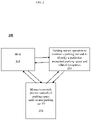
- FIG. 1 shows a flowchart of a method for automated cellular parking disclosed herein.
- the method is implemented in a parking area observed and controlled by an ACPS disclosed below, using the ACPS capabilities.
- the parking area includes controlled yet unmarked parking spaces which may be parallel to, vertical to, or at an angle with a curb or walkway. Alternatively, the parking area may be an open air parking lot with unmarked parking spaces.
- a particular car enters the parking area.
- at least one ACPS (“parking") sensor detects the particular car before or as it enters a particular available (empty) parking space.
- a host receives occupancy status for the particular parking space (now "occupied") as well as for other parking spaces from the parking sensor(s).
- a "host” is a back-end system which includes billing, customer service, parking space occupancy control and information, and enforcement facilities and capabilities.
- the host receives identifying parking space and particular car information. This information includes a precise parking space address and a driver ID or car license plate number of the particular car.
- the information is received respectively from a driver cell-phone Bluetooth unit or from the cell-phone.
- the information is received from a camera.
- the information is relayed to and received by the host without involvement of any dedicated in-car device, unlike in the method disclosed by PCT/IL2010/000685 .
- the host has access to a database which stores previously registered information on the particular car and its driver.
- the host associates the particular car with the precise parking space address and launches automatically a parking session.
- the parking sensor identifies the particular car as leaving the particular parking space and reports the particular parking space as available to the host. Consequently, in step, 112, the host terminates the parking session automatically, without involvement by the driver.
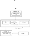
- FIG. 2 shows an embodiment of a general ACPS capable of implementing the method described in FIG. 1 , numbered 200.
- ACPS 200 comprises a host 202, at least one parking sensor 204 operative to monitor a parking car during a parking session as well as to provide parking space occupancy status (identify a particular parking space as occupied or unoccupied), and means 206 to provide a precise parking space address of the parking car as well as the car's ID.
- Host 202 is capable of communicating directly (e.g. through cellular communications) or indirectly (through an intermediary) with each parking sensor and parking car or its driver.
- Host 202 is further capable of storing registration information regarding car and drivers, and using such stored information before, during and after a parking session. Following are detailed descriptions of two implementations of such an ACPS.
- FIG. 3 shows a first implementation of an ACPS disclosed in FIG. 2 , numbered 300.
- ACPS 300 comprises a host 302 in communication with a plurality of parking sensors 304.
- host 302 may be similar to a host described in detail in PCT/IL2010/000685 .
- Sensors 304 are embedded together with Bluetooth devices 306 and power and communication means 308 in a buried cable 310.
- the embedded sensors and Bluetooth devices communicate with the host through means 308 and through a block controller 314 placed in a service box 316.
- Means 308 are wired to the block controller, which also powers sensors 304 and embedded Bluetooth devices 306.
- Cable 310 may be buried directly in the ground or may be placed inside a protective buried pipeline 312.
- buried pipeline and “buried cable” relate therefore to articles positioned under a paved surface along a road, sidewalk or parking curb and extending at least the length of a block, see FIG. 4 .
- a single block controller controls parking activity in a parking area, through interaction with buried sensors and communication devices in a cable connected thereto, and through further interaction with the host. The parking spaces in the block are thus “controlled” yet “unmarked” per the definition above.
- Embedded sensors 304 can sense the presence or absence of a parking car 320 in a particular parking space associated with a precise address.
- Embedded Bluetooth devices 306 communicate with a "user" Bluetooth device 318 (which may be located in the parking car 320 or carried by the driver, being integrated within the driver's cell-phone).
- "Bluetooth” is used herein as a particularly enabling example for a short range communication method and protocol which is independent of the cellular communication system in use. However, other communication methods and protocols may be used in some embodiments disclosed herein.
- the embedded sensors are chosen such that they have very short sensing ranges, on the order of 1-2 meters.
- the effective communication range of an embedded Bluetooth device is also relatively short, typically on the order of up to 10 meters.
- the user Bluetooth device is coupled to the ACPS Bluetooth network (which includes all embedded Bluetooth devices) during a registration procedure described below. This is done in a known way, and, advantageously, enables hands-off operation and communication once the user and embedded Bluetooth devices reach a communication distance.
- Each embedded Bluetooth device 306 is given its own unique ID number and is linked to the nearest street address in a way which enables the identification of the street address via the unique ID.
- each embedded sensor 304 is given its own unique ID number.
- embedded Bluetooth devices and user Bluetooth devices communicate directly with each other.
- pipeline 312 may be a protective, water-tight, flexible hollow tubular structure adapted for burial under a paved road surface.
- Pipeline 312 may be exemplarily made of a plastic or rubber material and may typically have a diameter of approximately 1-2". The material may be chosen to provide minimal impact on embedded sensing and Bluetooth communication ranges.
- cable 310 may be a cast cable with an embedded chain of wired electronic components (i.e. the sensors and transceivers) similar to (for example) LED decorating lighting cables. The cable may be pulled through pipeline 312 from the service box. If needed (e.g. for maintenance purposes), an existing cable can be easily replaced by a new cable.
- sensors 304 are magnetic sensors which are spaced appropriately along the cable.
- sensors 304 may be spaced 0.5-1 meter apart. Other spacing may be of course possible. In other embodiments, other types of embedded sensors which sense the presence or absence of a parked car in a particular parking space may serve purposes set forth herein.
- embedded Bluetooth devices 306 may be spaced apart such that each Bluetooth device is associated with a particular street address or position. The cast cable components may be positioned at short distances from one another in order to cover the parking area independently of the distances between the parking vehicles along the unmarked parking spaces.
- the pipeline may be hanged above the parking spaces.
- the embedded sensors and Bluetooth devices are electrically coupled to a Bluetooth link of the block controller, details of which are shown in FIG. 6 .
- Each block controller may be programmed by the host with the relevant parking regulations for each parking space. The programming may be done on-line or off-line.
- the regulations may exemplarily include parking rates for different times and/or users and parking time limits per day and/or per hour. The information may be updated in real time by the host.
- Box 316 may be similar to known street underground infrastructure service boxes ("S.B.”), and may be buried under the paved surface at a chosen location (e.g. proximal or distal end) of each parking block as shown in FIG. 4 .
- Block controller 314 powers and manages the operation of the sensors and the communication between (cable) embedded and user Bluetooth devices.
- Block controller 314 may be powered by an AC street lighting system (or alike) and may perform AC/DC conversion to provide DC power to various components.
- Block controller 314 may communicate by wired means or remotely with host 302 via a communication unit 612 in FIG. 6 , using for example cellular, WiFi or RF communications.
- FIG. 5 shows radial and longitudinal cross sections of pipeline 312 and cable 310 which illustrate the placement of the embedded sensors and Bluetooth devices and their wiring to the block controller.
- Each embedded sensor or Bluetooth device is operationally coupled to an electric power supply line 502 and to a communication line 504.
- Each sensor or a Bluetooth device includes a small non-volatile memory unit (not shown) which stores its respective unique ID. The ID may be programmed into the memory prior to the embedding of the Bluetooth and of the sensor units into cable 310. After inserting the cast cable and connecting its wires to the block controller, the initial programming of the block controller includes the marking of each component, (embedded sensor and Bluetooth device, through its ID) along the cable by the relevant street address.
- Every single component which is identified by its unique serial number along the cast cable represents a certain street address according to its geographical location.
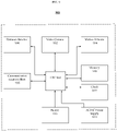
- FIG. 6 is a diagram of a typical block controller 314 positioned in every service box.
- Each block controller includes: a microprocessor or CPU 602 for controlling and managing the block's parking operation; a clock unit 604 for regulating the communication between CPU 602, embedded sensors 304, Bluetooth devices 306 and host 302; a memory unit 606 for storing embedded sensor and Bluetooth device IDs, respective parking addresses, relevant parking regulations, a block controller operating program, etc.; an AC/DC power supply unit 608 which, preferably, can accept AC power from the street infrastructure (lighting, etc.) and convert it to the DC power; an optional backup battery 610; a communication unit 612 for communicating with the host; a connection line 614 to the cable embedded Bluetooth devices; a connection line 616 to the cable embedded sensors; optionally a LED 618 for indicating the functionality of the CPU; and an antenna 620 for wireless communications with the host.
- a microprocessor or CPU 602 for controlling and managing the block's parking operation
- a clock unit 604 for regulating
- the block controller may communicate periodically according to a certain routine with all the cable components and the embedded sensors and Bluetooth devices of the local block. This may be done for instance by dedicating a connection period of 5-10 msec to each of the components, such that the block controller communicates with, and controls all the components approximately once a second. According to this routine, these cable components are powered only while in communication with the block controller. Thus, they need not be powered most of the time, saving energy while providing on-line control of the parking spaces.
- Embedded sensors may be powered in unmarked yet controlled parking spaces only during charging hours (for example during the day between 8am and 8pm).
- the embedded Bluetooth devices may be activated by the block controller only when the neighborhood sensors indicate an approaching car. The embedded Bluetooth devices can then be powered off once the parking handshake with a parking car is completed.
- the Bluetooth channel of driver's cell-phone is coupled to the Bluetooth channel of the operator.
- the driver needs not couple his Bluetooth to another Bluetooth device, but may be required to download a dedicated software application to his cell phone.
- the CPU in the block controller analyzes the strength and the intensity of electronic signals collected from the embedded sensors and selects an embedded Bluetooth device nearest to the parked car.
- the block controller then activates the selected Bluetooth device to launch communication with the user's Bluetooth device to perform a handshake procedure needed to initiate the current parking session.
- the user Bluetooth device may transmit only its registered given ID number or its cell-phone number. These automatically represent to the host all necessary driver and car details, such as driver's name, cell-phone number, car's license plate number, etc.
- the embedded Bluetooth device transmits to the driver's cell-phone information such as parking time limits, parking location address and rates.
- the block controller informs the host on the occupancy and the enforcement status of the particular parking space.
- the block controller After completing the handshake procedure, the block controller turns off the power to the selected embedded Bluetooth device but keeps powering the embedded sensors, according to the routine described above.
- the embedded sensors around the departing car sense the departing and update the block controller, which in return terminates the current parking session and updates the occupancy and the enforcement status accordingly.
- the block controller analyzes the sensors information, determines the precise car parking location and activates the nearest Bluetooth device for communicating with the parking car.
- the communication (“handshake") is explained with reference to Table 1 which shows a number of parking events involving four cars 320A, 320B, 320C and 320D and the actions taken by various embedded sensors and Bluetooth devices.
- the first column in Table 1 represents parking location address identified by IDs P200 to P202 (total of 3 parking spaces).
- the width of a parking space (illustrated by the number of cells related to PXXX, each cell representing a length of 1 meter) is 5 meter.
- the second column represents the embedded sensors along the cable, identified by IDs S100 to S114 (total of 15 sensors). The sensors are spaced 1 meter apart (thus one sensor per cell in the column).
- the third column represents the embedded Bluetooth devices along the cable identified by B300 to B302 (total of 3 units) and spaced 5 meter apart.
- Symbol “+” represents the status of a sensor which is “On” but which does not sense any car.
- Symbols "++” represents the status of a sensor which is “On” and which senses a car in its range (proximity).
- a second car 320B enters space P202 and parks in its middle (3 rd cell down the column) of a 5 meter parking space.
- Sensor S112 indicates this occupancy, while sensors S111 and S113 probably indicate the same with high certainty.
- Sensors S110, S114 may indicate the same, but with lesser certainty.
- CPU 602 selects Bluetooth device B302 to communicate with car 320B.
- a third car 320C enters space P201 and decides to park at a first end (top cell in the column) of the space.
- Sensor S105 and probably sensors S106 and S107 indicate the approaching of the car.
- sensors S104 and S105 are still busy sensing car 320A and therefore cannot be counted by CPU 602 for this analysis.
- CPU 602 is missing information.
- the distance of car 320C to Bluetooth device B300 is about the same as the distance to Bluetooth device B301.
- the nearest one left is Bluetooth device B301 and this will be the one selected for communicating with car 320C.
- CPU 602 selects the middle sensor S109 and, accordingly, activates Bluetooth device B301.
- the block controller After selecting the correct Bluetooth device nearest to a parking car, the block controller launches via this device a communication dialogue with the user Bluetooth device. The parties then automatically exchange ID information. While the driver's phone receives its precise location including address, parking time limit and parking rate, the embedded Bluetooth device receives the car's ID, which is forwarded to the block controller. At this stage, there are two options: in a manual option, the driver must confirm the start of the parking session by pressing a dedicated key of his/her phone, otherwise the parking session is not acknowledged. In an automatic option, (if this option was selected at the registration stage by the driver) the parking session starts automatically without confirmation. Next, the block controller sends the car ID to the host and updates the host regarding the occupancy of the particular parking space. The host activates the driver's account, starts counting the parking time and charges accordingly until the driver terminates the current parking session or the parking time limit expires, whichever comes first.
- the driver's phone must follow a pairing or coupling procedure with the system's embedded Bluetooth network for acquaintance and ease of communication. This can be done during the registration procedure.
- certain communication templates can also be programmed in the driver's cell-phone. All these registration procedures can also be provided to the driver remotely as a download from an operator's website.
- the parking session is confirmed. After confirmation (whether automatically or manually), the driver's account starts charging and the information regarding the occupancy of the parking space is updated and can be provided to the public by a variety of means, such as street electronic signs, GPS, etc.
- the occupation information received from the nearest sensors is still updated by the block controller, but an enforcement unit is informed and an inspector is sent to the particular parking space. Alternatively, a warning is issued to the driver prior to the deployment of the inspector.
- the nearest sensor senses the departure and alerts the host.
- the host stops charging, closes the billing session and updates the parking occupation information in real time. Since the billing session is stopped automatically when the car leaves the parking space, the driver is charged only for the time actually spent parking.
- FIG. 7 shows a second implementation not falling under the present invention of an ACPS disclosed in FIG. 2 , which uses a video camera 702 as a block parking sensor.
- camera or “video camera” is a unit which may include one or more cameras configured to detect, view, follow, identify and calibrate moving objects within a field of view.
- a camera unit has ability to calibrate a particular moving object in a multiplicity of positions and among a multiplicity of objects, and to distinguish between such objects.
- the camera unit may be adapted to perform 2D-to-3D conversion and processing, as known in the art. It may include other means for sensing the position and the movement of a detected item (e.g. a laser, a radar, etc.).
- a camera unit may also be capable of processing images and communicate with a host 302 via wired or wireless communication means.
- the camera may be LPN-enabled or LPR-enabled.
- Such a camera can be used to identify the particular parking car and to report to the host both the car ID and the precise parking space address, the latter obtained as described next.
- camera 702 views a parking area the length of a block along a sidewalk 720.
- the parking spaces are unmarked.
- the camera is capable of providing parking space occupancy information by identifying a particular space at a particular address as full or empty (see details below).
- the camera may programmed with software which divides the block into small segments of exemplarily 0.5-1.0 meter, marked in FIG. 7 as "a", "b", "c", "d”, etc.
- a group of several such segments represents a single parking space.
- Each segment is defined by a function which uses various parameters such as distance to the camera, angle to the camera, or both.
- each segment is referred to a street address to which it belongs. Exemplarily and as shown, segments a-d refer to address "Liberty 12" while segments e-h refers to address "Liberty 14".
- a particular car 320 enters the parking area represented by the block.
- the car is detected as it enters a particular unmarked parking space (e.g. a space located between segments h-j).
- the camera determines that the car parks in segment "h” i.e. in a particular unmarked parking space having 14 Liberty Street as address, and provides this information to the host.
- the host thus receives the precise address of the parking space from the camera.
- the host associates the particular car with "14 Liberty Street” and starts automatically a parking session for that car.
- a non-LPN- or LPR-enabled camera may also receive the identity of the particular car from a dedicated LPN (or LPR)-enabled camera which is positioned such that it reads the LPN of the cars moving into a controlled block.
- LPN or LPR
- the camera monitors the car and the parking space. When the car leaves the parking space, the camera alerts the host. The host then terminates the parking session automatically.
- FIG. 8 provides an example not falling under the present invention of how the camera senses occupancy status (i.e. whether a parking space is empty or occupied).
- occupancy status i.e. whether a parking space is empty or occupied.
- the camera is programmed to distinguish between pixels of a total viewed range 800 and pixels relating only to parking dedicated spaces 802 (a, b, c,...l).
- the camera is further programmed to recognize background colors and objects along the parking block.
- the camera determines from this disturbance that a car has parked in the parking space within Liberty 14 as address and reports this event to the host.
- the camera can be programmed with a variety of shapes of different typical vehicles. The camera may then recognize the shape of a car when it enters one the unmarked parking spaces, and report this particular (now occupied) space to the host.
- a camera can update the host regarding the occupancy status of the entire block. Assume that the length of the block is 60 meters, and that a typical car occupies a parking space 4 meters in length.
- the camera may measure the total length of the parked cars. Assume that five cars are now parked in the block. Their total length is 20 meters. Thus 40 meters of the total 60 (66%) are still free, and the camera reports to the host that 11 spaces (60/4-5) are still available. Alternatively, the camera can measure distances between the parked cars and determine how many spaces are still available.
- the driver has the option to confirm the parking session by another massage.
- the camera ignores the car and stops tracing it.
- FIG. 9 provides a schematic block diagram of a camera unit 900 not falling under the present invention.
- the unit is controlled by a CPU 904. It includes a motion detector 906 for monitoring cars, and distance and/or angle detectors 908 for identification of a final parking place from a parking car's position toward the camera.
- the camera unit may include other elements, similar to those in an embedded sensor unit, for example a memory 910, a clock 912, a power supply 914 and/or battery 915 and communication means 916 for communicating with the host.
- the camera After registration, whenever a car approaches a parking area, the camera follows its maneuvering until it comes to a stop in a particular parking space. The camera determines the precise location of the parking car and updates the host regarding the change of the occupancy status of this particular space/address. If the camera is non-LPR-enabled, the driver launches an "active handshake" by activating his/her GPS device and transmitting to the host the car location and the car or the driver ID. The host compares the location information received from both the camera and the GPS, and if they match, checks whether this car is registered and allowed to park at this particular space and time (residential or handicapped limitations). If yes, a confirmation massage is sent by the host to the driver's cell-phone and the handshake is completed.
- the camera If the camera is LPR-enabled, the camera sends to the host the parking car location together with its ID.
- the host performs the checks above and allows parking without the need for the driver to actively launch a handshake as above.
- the camera After completing the handshake procedure, the camera continues its monitoring and, as soon the car leaves the area, the camera updates the host, which in turn stops the parking session charge and updates parking occupancy information.
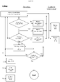
- FIG. 10 shows a flowchart of a detailed on-street parking procedure using an ACPS disclosed herein.
- the flowchart illustrates the electronic "dialogue" between parking cars and host from the point of view of the host, with one or more local cameras or a block controller serving as "eyes" to the host.
- a parking sensor determines whether a particular parking space is busy (occupied) or not. If the parking space is unoccupied (No), its status is reported in step 1002 to the host, directly (in the camera-based system) or indirectly (through a block controller in the embedded sensor system). The host then passes this information on to the public in step 1006. This can be done by various means, for example by using electronic boards or signs, or a dedicated navigation application of the user's cell-phone.
- the parking space is occupied, its status is reported to the host in step 1004 and a check on whether a handshake is performed is done in step 1008 .
- the host then informs the public as above.
- the block controller selects the nearest embedded sensor and communication device to represent the parked car.
- a handshake is not performed in a few cases: if the car ID does not match the registration details and/or the current parking regulation; if the parking car does not respond to the embedded communication device calls, or; if the location reported by the driver with the camera-based system doesn't match the location reported by the camera. In this case, the host alerts the parking enforcement in step 1012, and an inspector is sent to check the car in step 1014 to take appropriate action.
- the host communicates a confirmation to the driver (directly or indirectly) in step 1010.
- the confirmation may be transmitted together with other useful information such as parking time limit, parking fee, car parked address, etc.
- the host activates a parking time counter in step 1022, and a billing account for the parked car ("customer") in step 1016.
- the billing continues as long as a legal parking session is on, step 1022.
- the billing stops in step 1018 if either of two conditions are met: a) if the sensors (step 1000 ) report that the car has left the particular parking space (i.e. report that the particular parking space is "unoccupied"), or b) is a maximal parking time limit has been reached (step 1022 ), whichever comes first.
- the host prepares an invoice in step 1020. The invoice is then sent to the driver.
- step 1022 In case the parked car exceeds the maximal parking time limit in step 1022, which is controlled directly by the host (in the camera-based system) or by the block controller (in the embedded sensors system), the parking session is terminated in step 1010, the billing stops as above, and, in the embedded sensor system, the block controller alerts (via the host) the enforcement as above. In the camera-based system, the enforcement is alerted directly by the host.
- the ACPS disclosed herein may be applied in fully automated, barrier controlled parking garages.
- Each one of the garage parking spaces may be equipped with embedded ACPS embedded sensors or with the ACPS video cameras.
- the gate will be equipped with similar sensing means and with communication means either cell-phone transmitter or Bluetooth transmitter (for the Camera-based ACPS or for the embedded sensor ACPS respectively). This equipment will be able to open the gate once the registered driver approaches the gate.
- the parking garage controller will be similar to the block controller of the ACPS, will include a remote communication unit for communicating with the database of the host and means for controlling on-line the occupancy status of the garage parking spaces, which means are known and are in use in many garages.
- the ACPS sensor updates the controller and the latter checks if parking spaces are available. If yes, the gate communicates with the user's cell-phone device or with its Bluetooth device (for the camera ACPS or for the embedded sensor ACPS respectively) and runs the same handshake protocol as described for the ACPS above. In case the car is registered and recognized, the gate opens and the driver's account is charged from the entering time.
- the gate sensor activates the same communication unit, which in return captures the ID of the departing car by communicating with the driver's cell-phone or with his Bluetooth (with the camera ACPS or the embedded sensors ACPS respectively).
- the gate opens again and the operator stops charging the driver's account.
Landscapes
- Business, Economics & Management (AREA)
- Finance (AREA)
- Physics & Mathematics (AREA)
- General Physics & Mathematics (AREA)
- Traffic Control Systems (AREA)
- Steering Control In Accordance With Driving Conditions (AREA)
Claims (12)
- Procédé de stationnement automatique d'un véhicule dans une aire de stationnement avec des places de stationnement banalisées contrôlées, le procédé étant exécuté par un système de stationnement cellulaire automatisé (ACPS) comprenant un hôte (302), une pluralité de capteurs de stationnement (304), des dispositifs Bluetooth (306) ou des appareils utilisant d'autres procédés et protocoles de communication, des moyens d'alimentation et de communication (308) et un contrôleur de bloc (314) placé dans un coffret de service (316), les capteurs de stationnement (304) étant incorporés dans un câble (310) avec les dispositifs Bluetooth (306) ou les appareils utilisant d'autres procédés et protocoles de communication et avec les moyens d'alimentation et de communication (308), dans lequel les capteurs de stationnement (304) et les dispositifs Bluetooth (306) ou les appareils utilisant d'autres procédés et protocoles de communication sont configurés pour communiquer avec l'hôte (302) via les moyens d'alimentation et de communication (308) et via le contrôleur de bloc (314), dans lequel les moyens d'alimentation et de communication (308) sont câblés au contrôleur de bloc (314), qui alimente aussi les capteurs de stationnement (304) et les dispositifs Bluetooth (306), ou alimente les capteurs de stationnement (304) et les dispositifs en utilisant d'autres procédés et protocoles de communication, et dans lequel le procédé exécute les étapes consistant à :a) détecter, par les capteurs de stationnement (304) si un véhicule pénètre dans une place de stationnement banalisée particulière dans l'aire de stationnement avec des places de stationnement banalisées contrôlées, dans lequel le câble (310) est placé à l'intérieur d'une canalisation de protection (312) qui est soit enterrée sous la surface d'une rue soit d'un trottoir, ou suspendue au-dessus des places de stationnement, et dans lequel les dispositifs Bluetooth (306) ou les appareils utilisant d'autres procédés et protocoles de communication reçoivent chacun leur propre numéro d'identification unique respectif et sont liés à une adresse de rue la plus proche d'une manière qui permet l'identification de l'adresse de rue la plus proche via leur numéro d'identification unique respectif ;a1) sélectionner, par le contrôleur de bloc, le dispositif Bluetooth (306) ou appareil correct utilisant d'autres procédés et protocoles de communication, dans lequel le dispositif Bluetooth ou appareil correct utilisant d'autres procédés et protocoles de communication est celui le plus proche du véhicule de stationnement ;a2) lancer, par le contrôleur de bloc, via le dispositif Bluetooth ou l'appareil correct utilisant d'autres procédés et protocoles de communication, un dialogue de communication avec un appareil utilisateur situé dans le véhicule de stationnement ou porté par le conducteur, étant intégré dans le téléphone portable du conducteur ;b) recevoir, au niveau du dispositif Bluetooth (306) ou des dispositifs corrects utilisant d'autres procédés et protocoles de communication, des informations identifiant le véhicule à partir du dispositif utilisateur (318) ;c) recevoir, au niveau de l'hôte (302), des informations d'occupation relatives à des espaces de stationnement banalisés provenant des capteurs de stationnement (304) ;d) recevoir, au niveau de l'hôte (302), les informations identifiant le véhicule et une adresse précise de l'espace de stationnement banalisé particulier du dispositif Bluetooth correct (306) ou du dispositif utilisant d'autres procédés et protocoles de communication,e) associer, au niveau de l'hôte (302), les informations identifiant le véhicule à l'adresse précise de la place de stationnement banalisée particulière ;f) démarrer automatiquement une session de stationnement au niveau de l'hôte (302) ; etg) mettre fin automatiquement à la session de stationnement au niveau de l'hôte (302) lors du départ du véhicule de l'espace de stationnement banalisé particulier, dans lequel au moins un capteur de stationnement (304) identifie le moment où le véhicule quitte l'espace de stationnement banalisé particulier et rapporte à l'hôte (302) l'espace de stationnement particulier étant disponible,moyennant quoi les étapes (a) à (g) sont exécutées sans utiliser un dispositif embarqué dédié.
- Procédé selon la revendication 1, dans lequel le véhicule a un conducteur respectif et dans lequel l'étape de réception d'informations identifiant un véhicule comprend la réception d'un identifiant du conducteur par communication cellulaire depuis le conducteur.
- Procédé selon la revendication 1, dans lequel l'étape de démarrage automatique de la session de stationnement comprend la confirmation de la session de stationnement, la confirmation que le véhicule est enregistré et la confirmation que le véhicule ne stationne pas illégalement, et après confirmation, le démarrage de la facturation d'un compte du chauffeur respectif et la mise à jour, au niveau de l'hôte, des informations relatives à l'occupation de la place de stationnement.
- Procédé selon la revendication 3, dans lequel au cas où le véhicule n'est pas identifié, au cas où le stationnement n'est pas confirmé, ou au cas où le véhicule particulier se gare illégalement, les informations d'occupation de l'espace de stationnement sont toujours mises à jour par le contrôleur de bloc (314) qui reçoit les informations d'occupation de l'espace de stationnement des capteurs de stationnement (304) via des moyens d'alimentation et de communication (308), et une unité d'exécution est informée et un inspecteur est envoyé à l'espace de stationnement particulier, ou un avertissement est émis vers le conducteur respectif avant l'envoi de l'inspecteur.
- Procédé selon la revendication 1, dans lequel lorsque le véhicule quitte la place de stationnement, le capteur de stationnement le plus proche (304) détecte le départ et alerte l'hôte, qui, en retour, arrête la facturation, ferme une session de facturation et met à jour les informations d'occupation du stationnement en temps réel de sorte que le conducteur respectif ne soit facturé que pour le temps réellement passé à stationner.
- Système de stationnement automatique d'un véhicule dans une aire de stationnement à places de stationnement banalisées contrôlées, comprenant :a) un hôte (302) agissant en tant que système de gestion ;
a1) un dispositif utilisateur situé dans un véhicule de stationnement ou porté par le conducteur du véhicule, étant intégré dans le téléphone portable du conducteur ;b) une pluralité de capteurs de stationnement (304), des dispositifs Bluetooth (306) ou des appareils utilisant d'autres procédés et protocoles de communication, des moyens d'alimentation et de communication (308) et un contrôleur de bloc placé dans un boîtier de service (306), les capteurs de stationnement (304) étant intégrés dans un câble avec les dispositifs Bluetooth (306) ou les appareils utilisant d'autres procédés et protocoles de communication et avec les moyens d'alimentation et de communication, dans lequel les capteurs de stationnement (304) et les dispositifs Bluetooth (306) ou les appareils utilisant d'autres communications des procédés et des protocoles sont configurés pour communiquer avec l'hôte (302) via les moyens d'alimentation et de communication (308) et via le contrôleur de bloc (304), les moyens d'alimentation et de communication (308) étant câblés au contrôleur de bloc (304), qui est également configuré pour alimenter les capteurs de stationnement (304) et les dispositifs Bluetooth (306), ou pour alimenter les capteurs de stationnement (304) et les appareils utilisant d'autres procédés et protocoles de communication, dans lequel le câble est placé à l'intérieur d'une canalisation de protection (312) qui est soit enterrée sous la surface d'une rue ou d'un trottoir, soit suspendue au-dessus des places de stationnement ;dans lequel les capteurs de stationnement sont configurés pour surveiller un véhicule et pour identifier une place de stationnement banalisée particulière et l'occupation associée,dans lequel les dispositifs Bluetooth (306) ou les appareils utilisant d'autres procédés et protocoles de communication reçoivent chacun leur propre numéro d'identification unique respectif et sont liés à une adresse de rue la plus proche d'une manière qui permet l'identification de l'adresse de rue la plus proche via leur numéro d'identification unique respectif,dans lequel les capteurs de stationnement (304) sont configurés pour détecter si le véhicule pénètre dans une place de stationnement banalisée particulière (100) dans la zone de stationnement avec des places de stationnement banalisées contrôlées,dans lequel le contrôleur de bloc (314) est configuré pour sélectionner le dispositif Bluetooth correct (306) ou un dispositif utilisant d'autres procédés et protocoles de communication, dans lequel le dispositif Bluetooth ou l'appareil correct utilisant d'autres procédés et protocoles de communication est le plus proche du véhicule de stationnement ;dans lequel le contrôleur de bloc (314) est configuré pour lancer, via le dispositif Bluetooth ou l'appareil correct utilisant d'autres procédés et protocoles de communication, un dialogue de communication avec le dispositif utilisateur ;dans lequel le dispositif Bluetooth correct (306) ou le dispositif utilisant d'autres procédés et protocoles de communication est configuré pour recevoir des informations identifiant le dispositif utilisateur,dans lequel l'hôte (302) est configuré pour recevoir des informations d'occupation relatives à des places de stationnement banalisées des capteurs de stationnement (304),dans lequel l'hôte (302) est configuré pour recevoir les informations identifiant le véhicule et une adresse précise de la place de stationnement banalisée particulière du dispositif Bluetooth (306) ou de l'appareil correct utilisant d'autres procédés et protocoles de communication,dans lequel l'hôte (302) est configuré pour associer les informations identifiant le véhicule à l'adresse précise de l'espace de stationnement banalisé particulière,et puis pour démarrer automatiquement une session de stationnement session, etdans lequel l'hôte (302) est configuré pour mettre fin automatiquement à la session de stationnement lors du départ du véhicule de l'espace de stationnement banalisé particulier, dans lequel le au moins un capteur de stationnement (304) identifie le moment où le véhicule quitte l'espace de stationnement banalisé particulier et signale à l'hôte (302) l'espace de stationnement particulier comme étant disponible,moyennant quoi ni le dispositif utilisateur (318) ni aucun autre dispositif compris dans le système n'est un dispositif embarqué dédié. - Système selon la revendication 6, dans lequel l'hôte (302) est en outre opérationnel pour fournir publiquement des informations relatives à l'occupation de l'espace de stationnement.
- Système selon une quelconque des revendications 6 à 7, dans lequel les capteurs de stationnement (304) sont incorporés dans un câble, dans lequel le câble est placé à l'intérieur d'une canalisation de protection (312) qui est enterrée sous la surface d'une rue ou d'un trottoir, dans lequel le câble comprenant les capteurs de stationnement (304) s'étend au moins sur la longueur d'un bloc de stationnement.
- Système selon la revendication 8, comprenant un bloc d'alimentation AC/DC (608) qui accepte le courant alternatif de l'infrastructure routière pour la conversion du courant alternatif en courant continu, le bloc d'alimentation AC/DC (608) étant compris dans le contrôleur de bloc (314).
- Système selon la revendication 8, dans lequel le contrôleur de bloc (314) est programmé par l'hôte (312) avec des règlements de stationnement pertinents pour chaque place de stationnement.
- Système selon une quelconque des revendications 6 à 10, dans lequel chaque capteur de stationnement (304) est fonctionnellement couplé à une alimentation électrique (502) et à une ligne de communication (504).
- Système selon une quelconque des revendications 6 à 11, dans lequel les capteurs de stationnement (304) sont alimentés dans des espaces de stationnement banalisés mais contrôlés uniquement pendant les heures de facturation.
Priority Applications (1)
| Application Number | Priority Date | Filing Date | Title |
|---|---|---|---|
| HRP20221144TT HRP20221144T1 (hr) | 2012-01-14 | 2013-01-11 | Postupci i sustavi za automatizirano mobilno parkiranje s kontrolom raspoloživih mjesta |
Applications Claiming Priority (2)
| Application Number | Priority Date | Filing Date | Title |
|---|---|---|---|
| US201261586758P | 2012-01-14 | 2012-01-14 | |
| PCT/IB2013/050284 WO2013105067A1 (fr) | 2012-01-14 | 2013-01-11 | Procédés et systèmes de stationnement cellulaire automatisé comprenant régulation d'occupation |
Publications (3)
| Publication Number | Publication Date |
|---|---|
| EP2867866A1 EP2867866A1 (fr) | 2015-05-06 |
| EP2867866A4 EP2867866A4 (fr) | 2016-05-25 |
| EP2867866B1 true EP2867866B1 (fr) | 2022-08-10 |
Family
ID=48781094
Family Applications (1)
| Application Number | Title | Priority Date | Filing Date |
|---|---|---|---|
| EP13735637.4A Active EP2867866B1 (fr) | 2012-01-14 | 2013-01-11 | Procédés et systèmes de stationnement cellulaire automatisé comprenant régulation d'occupation |
Country Status (5)
| Country | Link |
|---|---|
| US (2) | US20140372185A1 (fr) |
| EP (1) | EP2867866B1 (fr) |
| HR (1) | HRP20221144T1 (fr) |
| IL (1) | IL233528B (fr) |
| WO (1) | WO2013105067A1 (fr) |
Families Citing this family (30)
| Publication number | Priority date | Publication date | Assignee | Title |
|---|---|---|---|---|
| US20120078686A1 (en) * | 2010-09-27 | 2012-03-29 | Bashani Gilad G | Parking status system |
| AU2014201070A1 (en) * | 2013-05-31 | 2014-12-18 | Pinpark Ip Pty Ltd | Implementing Location Based Actions |
| US20150071274A1 (en) * | 2013-09-11 | 2015-03-12 | Emanate Wireless, Inc. | Cable assembly with integrated wireless proximity sensors |
| JP6237128B2 (ja) * | 2013-11-01 | 2017-11-29 | 株式会社デンソー | 車両用駐車自動課金装置、課金処理アプリケーションプログラム、駐車エリア自動課金システム |
| US9635115B2 (en) * | 2014-03-07 | 2017-04-25 | International Business Machines Corporation | Unused location discriminator |
| US10117043B2 (en) * | 2014-09-22 | 2018-10-30 | Symbol Technologies, Llc | Serially-connected bluetooth low energy nodes |
| WO2016053073A1 (fr) * | 2014-09-30 | 2016-04-07 | PALAZUELOS VALDES, Alvaro | Gestion de stationnement assisté par vision artificielle |
| GB2536663A (en) * | 2015-03-24 | 2016-09-28 | Faxi Ltd | A method, system and device for determining close proximity of two or more persons |
| DE102015205634A1 (de) * | 2015-03-27 | 2016-09-29 | Robert Bosch Gmbh | Verfahren zum Erkennen von Bewegungen von Objekten auf einer Abstellfläche für Fahrzeuge |
| US10288733B2 (en) | 2015-04-28 | 2019-05-14 | Robert Bosch Gmbh | Method for forecasting parking area availability of a street section |
| WO2016178220A1 (fr) * | 2015-05-04 | 2016-11-10 | Pink Park Ltd. | Système et procédé de gestion d'espace de stationnement |
| DE102015211114A1 (de) * | 2015-06-17 | 2016-12-22 | Robert Bosch Gmbh | Verwaltung eines Parkplatzes |
| GB2541497B (en) * | 2015-06-17 | 2021-06-16 | Bosch Gmbh Robert | Management of a car park |
| DE102016210297A1 (de) | 2015-06-17 | 2016-12-22 | Robert Bosch Gmbh | Verwaltung eines Parkplatzes |
| IL244938A0 (en) * | 2015-11-23 | 2016-07-31 | Cellopark Technologies Ltd | System, device and method for parking vehicles |
| US9691190B2 (en) * | 2015-11-30 | 2017-06-27 | Faraday & Future Inc. | Location based parking meter time reminder |
| WO2018125796A1 (fr) * | 2016-12-27 | 2018-07-05 | Denso International America, Inc. | Système et procédé destinés à une communication de capteur de microlocalisation |
| WO2018204210A1 (fr) * | 2017-05-01 | 2018-11-08 | Parkofon Inc. | Système et procédé de détermination de localisation à haute précision et de stationnement |
| CN107205037A (zh) * | 2017-06-19 | 2017-09-26 | 深圳市盛路物联通讯技术有限公司 | 一种基于汇聚平台的停车管理方法及系统 |
| CN107346562A (zh) * | 2017-07-06 | 2017-11-14 | 深圳市海云图新能源有限公司 | 一种智能全自动停取车系统 |
| CN111052199A (zh) * | 2017-07-18 | 2020-04-21 | 罗伯特·博世有限公司 | 用于预测街道区段的停放区域可用性的方法 |
| GB2567618A (en) * | 2017-09-20 | 2019-04-24 | Yellow Line Parking Ltd | Parking system |
| CN107610516A (zh) * | 2017-09-28 | 2018-01-19 | 深圳前海弘稼科技有限公司 | 停车信息的处理方法及装置、计算机装置及可读存储介质 |
| ES2711817A1 (es) * | 2017-11-03 | 2019-05-07 | Vega Israel Abrante | Sistema de control de estacionamientos autónomo en zona viaria al aire libre. |
| US10825116B2 (en) | 2017-12-22 | 2020-11-03 | Carrier Corporation | Vehicle parking space protector and access control by a vehicle operator |
| CN108091054A (zh) * | 2017-12-25 | 2018-05-29 | 深圳无疆新能科技有限公司 | 一种高智能停车充电控制系统及方法 |
| CN108280572A (zh) * | 2018-01-15 | 2018-07-13 | 西安艾润物联网技术服务有限责任公司 | 车辆能源补充的调度方法、系统及计算机可读存储介质 |
| US10580300B1 (en) | 2018-08-22 | 2020-03-03 | Ford Global Technologies, Llc | Parking management systems and methods |
| US11556133B2 (en) | 2019-07-26 | 2023-01-17 | International Business Machines Corporation | Inter-vehicle collaboration to modify a parking queue |
| CN115240436B (zh) * | 2022-09-23 | 2022-12-16 | 杭州立方控股股份有限公司 | 一种地磁、摄像机与多收费员协同的智能停车管理方法 |
Family Cites Families (9)
| Publication number | Priority date | Publication date | Assignee | Title |
|---|---|---|---|---|
| AU2173192A (en) * | 1991-07-08 | 1993-02-11 | Philippe Schick | Car park management method and system |
| FR2872321B1 (fr) * | 2004-06-25 | 2006-09-01 | Technolia Sarl Sarl | Ensemble de gestion de places de stationnement, avec borne de controle d'usager autorise et de signalement a un poste de controle, et logiciel d'application |
| WO2006067813A1 (fr) * | 2004-12-21 | 2006-06-29 | Gianfranco Zanotti | Systeme automatique integre servant a gerer l'acces de vehicules a des aires de stationnement surveillees |
| US7667619B2 (en) * | 2006-08-02 | 2010-02-23 | Montgomery Sr Phil | Parking violation surveillance system |
| GB2441382B (en) * | 2006-08-29 | 2009-10-14 | Ranger Services Ltd | Automated parking system |
| WO2008104053A1 (fr) * | 2007-02-28 | 2008-09-04 | Mitschele Frederick L | Procédé et système de respect de stationnement utilisant des détecteurs au sol sans fil |
| US7893847B2 (en) | 2008-07-09 | 2011-02-22 | Yahoo! Inc. | Real time detection of parking space availability |
| EP2164043A1 (fr) | 2008-09-12 | 2010-03-17 | March Networks Corporation | Calibration et calcul d'une perspective d'une caméra vidéo |
| EP2473947A4 (fr) * | 2009-08-31 | 2015-11-04 | Parx Ltd | Système de stationnement entièrement automatisé |
-
2013
- 2013-01-11 WO PCT/IB2013/050284 patent/WO2013105067A1/fr active Application Filing
- 2013-01-11 EP EP13735637.4A patent/EP2867866B1/fr active Active
- 2013-01-11 HR HRP20221144TT patent/HRP20221144T1/hr unknown
- 2013-02-11 US US14/370,783 patent/US20140372185A1/en not_active Abandoned
-
2014
- 2014-07-06 IL IL233528A patent/IL233528B/en active IP Right Grant
-
2019
- 2019-03-12 US US16/299,897 patent/US20190213802A1/en not_active Abandoned
Also Published As
| Publication number | Publication date |
|---|---|
| HRP20221144T1 (hr) | 2022-11-25 |
| WO2013105067A1 (fr) | 2013-07-18 |
| EP2867866A4 (fr) | 2016-05-25 |
| US20190213802A1 (en) | 2019-07-11 |
| US20140372185A1 (en) | 2014-12-18 |
| EP2867866A1 (fr) | 2015-05-06 |
| IL233528B (en) | 2019-05-30 |
Similar Documents
| Publication | Publication Date | Title |
|---|---|---|
| EP2867866B1 (fr) | Procédés et systèmes de stationnement cellulaire automatisé comprenant régulation d'occupation | |
| US11200756B2 (en) | Method for detecting parked vehicles and billing parking charges | |
| AU2012200537B2 (en) | Parking lot | |
| US8624756B2 (en) | Fully automated parking system | |
| CN109191598B (zh) | 车位管理系统及其管理方法 | |
| US20130073350A1 (en) | Parking space management system and method | |
| US10643471B2 (en) | Method for detecting parked vehicles | |
| EP1898360B1 (fr) | Système d'enregistrement et de paiement d'heure de parking | |
| KR101831987B1 (ko) | 주차공간 유료 공유 방법 및 이를 위한 시스템 | |
| EP2973434B1 (fr) | Système de surveillance pour parc de stationnement | |
| EP3656604A2 (fr) | Système de surveillance de station de charge | |
| KR101778780B1 (ko) | 노상 주차장 관리 시스템 | |
| CN107316493B (zh) | 一种用于停车场的停车管理系统 | |
| KR20190009645A (ko) | 주차위치 확인시스템 | |
| CN112687124A (zh) | 基于etc的路侧图像识别无感支付停车系统及方法 | |
| WO2019221612A1 (fr) | Système et procédé de stationnement | |
| CN109235318B (zh) | 智能车位锁及其控制方法和装置 | |
| US20240185723A1 (en) | Apparatus for controlling parking in a parking stall | |
| CN113034705A (zh) | 一种智能地锁以及应用该地锁的停车位出租收费系统 | |
| US20240321108A1 (en) | Apparatus for charging a vehicle with electricity | |
| KR101298836B1 (ko) | 거주자 우선 주차 공간 운영 시스템 | |
| KR102214846B1 (ko) | Gps를 이용한 주차관리 시스템 및 이를 위한 gps유닛 | |
| US11922811B2 (en) | Apparatus for controlling parking in a parking stall | |
| KR20170073429A (ko) | 공유 주차 관제 방법, 그를 수행하기 위한 공유 주차 관제 서버 및 시스템 | |
| WO2022232902A1 (fr) | Appareil de contrôle et de monétisation de stationnement dans un espace de stationnement |
Legal Events
| Date | Code | Title | Description |
|---|---|---|---|
| REG | Reference to a national code |
Ref country code: HR Ref legal event code: TUEP Ref document number: P20221144 Country of ref document: HR |
|
| PUAI | Public reference made under article 153(3) epc to a published international application that has entered the european phase |
Free format text: ORIGINAL CODE: 0009012 |
|
| 17P | Request for examination filed |
Effective date: 20141120 |
|
| AK | Designated contracting states |
Kind code of ref document: A1 Designated state(s): AL AT BE BG CH CY CZ DE DK EE ES FI FR GB GR HR HU IE IS IT LI LT LU LV MC MK MT NL NO PL PT RO RS SE SI SK SM TR |
|
| RA4 | Supplementary search report drawn up and despatched (corrected) |
Effective date: 20160422 |
|
| RIC1 | Information provided on ipc code assigned before grant |
Ipc: G07B 15/02 20060101AFI20160418BHEP Ipc: G08G 1/14 20060101ALI20160418BHEP |
|
| STAA | Information on the status of an ep patent application or granted ep patent |
Free format text: STATUS: EXAMINATION IS IN PROGRESS |
|
| 17Q | First examination report despatched |
Effective date: 20180419 |
|
| STAA | Information on the status of an ep patent application or granted ep patent |
Free format text: STATUS: EXAMINATION IS IN PROGRESS |
|
| RAP1 | Party data changed (applicant data changed or rights of an application transferred) |
Owner name: MOBILISIS D.O.O. |
|
| RIN1 | Information on inventor provided before grant (corrected) |
Inventor name: GANOT, ZVI |
|
| GRAP | Despatch of communication of intention to grant a patent |
Free format text: ORIGINAL CODE: EPIDOSNIGR1 |
|
| STAA | Information on the status of an ep patent application or granted ep patent |
Free format text: STATUS: GRANT OF PATENT IS INTENDED |
|
| INTG | Intention to grant announced |
Effective date: 20210924 |
|
| GRAJ | Information related to disapproval of communication of intention to grant by the applicant or resumption of examination proceedings by the epo deleted |
Free format text: ORIGINAL CODE: EPIDOSDIGR1 |
|
| STAA | Information on the status of an ep patent application or granted ep patent |
Free format text: STATUS: EXAMINATION IS IN PROGRESS |
|
| INTC | Intention to grant announced (deleted) | ||
| GRAP | Despatch of communication of intention to grant a patent |
Free format text: ORIGINAL CODE: EPIDOSNIGR1 |
|
| STAA | Information on the status of an ep patent application or granted ep patent |
Free format text: STATUS: GRANT OF PATENT IS INTENDED |
|
| INTG | Intention to grant announced |
Effective date: 20220228 |
|
| GRAS | Grant fee paid |
Free format text: ORIGINAL CODE: EPIDOSNIGR3 |
|
| GRAA | (expected) grant |
Free format text: ORIGINAL CODE: 0009210 |
|
| STAA | Information on the status of an ep patent application or granted ep patent |
Free format text: STATUS: THE PATENT HAS BEEN GRANTED |
|
| AK | Designated contracting states |
Kind code of ref document: B1 Designated state(s): AL AT BE BG CH CY CZ DE DK EE ES FI FR GB GR HR HU IE IS IT LI LT LU LV MC MK MT NL NO PL PT RO RS SE SI SK SM TR |
|
| REG | Reference to a national code |
Ref country code: GB Ref legal event code: FG4D |
|
| REG | Reference to a national code |
Ref country code: AT Ref legal event code: REF Ref document number: 1511122 Country of ref document: AT Kind code of ref document: T Effective date: 20220815 Ref country code: CH Ref legal event code: EP |
|
| REG | Reference to a national code |
Ref country code: IE Ref legal event code: FG4D |
|
| REG | Reference to a national code |
Ref country code: DE Ref legal event code: R096 Ref document number: 602013082286 Country of ref document: DE |
|
| REG | Reference to a national code |
Ref country code: NL Ref legal event code: FP |
|
| REG | Reference to a national code |
Ref country code: SK Ref legal event code: T3 Ref document number: E 40439 Country of ref document: SK |
|
| REG | Reference to a national code |
Ref country code: HR Ref legal event code: T1PR Ref document number: P20221144 Country of ref document: HR |
|
| REG | Reference to a national code |
Ref country code: LT Ref legal event code: MG9D |
|
| REG | Reference to a national code |
Ref country code: HR Ref legal event code: ODRP Ref document number: P20221144 Country of ref document: HR Payment date: 20221229 Year of fee payment: 11 |
|
| PG25 | Lapsed in a contracting state [announced via postgrant information from national office to epo] |
Ref country code: SE Free format text: LAPSE BECAUSE OF FAILURE TO SUBMIT A TRANSLATION OF THE DESCRIPTION OR TO PAY THE FEE WITHIN THE PRESCRIBED TIME-LIMIT Effective date: 20220810 Ref country code: RS Free format text: LAPSE BECAUSE OF FAILURE TO SUBMIT A TRANSLATION OF THE DESCRIPTION OR TO PAY THE FEE WITHIN THE PRESCRIBED TIME-LIMIT Effective date: 20220810 Ref country code: PT Free format text: LAPSE BECAUSE OF FAILURE TO SUBMIT A TRANSLATION OF THE DESCRIPTION OR TO PAY THE FEE WITHIN THE PRESCRIBED TIME-LIMIT Effective date: 20221212 Ref country code: NO Free format text: LAPSE BECAUSE OF FAILURE TO SUBMIT A TRANSLATION OF THE DESCRIPTION OR TO PAY THE FEE WITHIN THE PRESCRIBED TIME-LIMIT Effective date: 20221110 Ref country code: LV Free format text: LAPSE BECAUSE OF FAILURE TO SUBMIT A TRANSLATION OF THE DESCRIPTION OR TO PAY THE FEE WITHIN THE PRESCRIBED TIME-LIMIT Effective date: 20220810 Ref country code: LT Free format text: LAPSE BECAUSE OF FAILURE TO SUBMIT A TRANSLATION OF THE DESCRIPTION OR TO PAY THE FEE WITHIN THE PRESCRIBED TIME-LIMIT Effective date: 20220810 Ref country code: FI Free format text: LAPSE BECAUSE OF FAILURE TO SUBMIT A TRANSLATION OF THE DESCRIPTION OR TO PAY THE FEE WITHIN THE PRESCRIBED TIME-LIMIT Effective date: 20220810 Ref country code: ES Free format text: LAPSE BECAUSE OF FAILURE TO SUBMIT A TRANSLATION OF THE DESCRIPTION OR TO PAY THE FEE WITHIN THE PRESCRIBED TIME-LIMIT Effective date: 20220810 |
|
| PG25 | Lapsed in a contracting state [announced via postgrant information from national office to epo] |
Ref country code: PL Free format text: LAPSE BECAUSE OF FAILURE TO SUBMIT A TRANSLATION OF THE DESCRIPTION OR TO PAY THE FEE WITHIN THE PRESCRIBED TIME-LIMIT Effective date: 20220810 Ref country code: IS Free format text: LAPSE BECAUSE OF FAILURE TO SUBMIT A TRANSLATION OF THE DESCRIPTION OR TO PAY THE FEE WITHIN THE PRESCRIBED TIME-LIMIT Effective date: 20221210 Ref country code: GR Free format text: LAPSE BECAUSE OF FAILURE TO SUBMIT A TRANSLATION OF THE DESCRIPTION OR TO PAY THE FEE WITHIN THE PRESCRIBED TIME-LIMIT Effective date: 20221111 |
|
| PG25 | Lapsed in a contracting state [announced via postgrant information from national office to epo] |
Ref country code: SM Free format text: LAPSE BECAUSE OF FAILURE TO SUBMIT A TRANSLATION OF THE DESCRIPTION OR TO PAY THE FEE WITHIN THE PRESCRIBED TIME-LIMIT Effective date: 20220810 Ref country code: RO Free format text: LAPSE BECAUSE OF FAILURE TO SUBMIT A TRANSLATION OF THE DESCRIPTION OR TO PAY THE FEE WITHIN THE PRESCRIBED TIME-LIMIT Effective date: 20220810 Ref country code: DK Free format text: LAPSE BECAUSE OF FAILURE TO SUBMIT A TRANSLATION OF THE DESCRIPTION OR TO PAY THE FEE WITHIN THE PRESCRIBED TIME-LIMIT Effective date: 20220810 Ref country code: CZ Free format text: LAPSE BECAUSE OF FAILURE TO SUBMIT A TRANSLATION OF THE DESCRIPTION OR TO PAY THE FEE WITHIN THE PRESCRIBED TIME-LIMIT Effective date: 20220810 |
|
| REG | Reference to a national code |
Ref country code: DE Ref legal event code: R097 Ref document number: 602013082286 Country of ref document: DE |
|
| PG25 | Lapsed in a contracting state [announced via postgrant information from national office to epo] |
Ref country code: EE Free format text: LAPSE BECAUSE OF FAILURE TO SUBMIT A TRANSLATION OF THE DESCRIPTION OR TO PAY THE FEE WITHIN THE PRESCRIBED TIME-LIMIT Effective date: 20220810 |
|
| PLBE | No opposition filed within time limit |
Free format text: ORIGINAL CODE: 0009261 |
|
| STAA | Information on the status of an ep patent application or granted ep patent |
Free format text: STATUS: NO OPPOSITION FILED WITHIN TIME LIMIT |
|
| PG25 | Lapsed in a contracting state [announced via postgrant information from national office to epo] |
Ref country code: AL Free format text: LAPSE BECAUSE OF FAILURE TO SUBMIT A TRANSLATION OF THE DESCRIPTION OR TO PAY THE FEE WITHIN THE PRESCRIBED TIME-LIMIT Effective date: 20220810 |
|
| 26N | No opposition filed |
Effective date: 20230511 |
|
| PG25 | Lapsed in a contracting state [announced via postgrant information from national office to epo] |
Ref country code: SI Free format text: LAPSE BECAUSE OF FAILURE TO SUBMIT A TRANSLATION OF THE DESCRIPTION OR TO PAY THE FEE WITHIN THE PRESCRIBED TIME-LIMIT Effective date: 20220810 |
|
| REG | Reference to a national code |
Ref country code: CH Ref legal event code: PL |
|
| GBPC | Gb: european patent ceased through non-payment of renewal fee |
Effective date: 20230111 |
|
| PG25 | Lapsed in a contracting state [announced via postgrant information from national office to epo] |
Ref country code: LU Free format text: LAPSE BECAUSE OF NON-PAYMENT OF DUE FEES Effective date: 20230111 |
|
| PG25 | Lapsed in a contracting state [announced via postgrant information from national office to epo] |
Ref country code: LI Free format text: LAPSE BECAUSE OF NON-PAYMENT OF DUE FEES Effective date: 20230131 Ref country code: GB Free format text: LAPSE BECAUSE OF NON-PAYMENT OF DUE FEES Effective date: 20230111 Ref country code: CH Free format text: LAPSE BECAUSE OF NON-PAYMENT OF DUE FEES Effective date: 20230131 |
|
| PG25 | Lapsed in a contracting state [announced via postgrant information from national office to epo] |
Ref country code: FR Free format text: LAPSE BECAUSE OF NON-PAYMENT OF DUE FEES Effective date: 20230131 |
|
| REG | Reference to a national code |
Ref country code: HR Ref legal event code: ODRP Ref document number: P20221144 Country of ref document: HR Payment date: 20240105 Year of fee payment: 12 |
|
| PG25 | Lapsed in a contracting state [announced via postgrant information from national office to epo] |
Ref country code: IE Free format text: LAPSE BECAUSE OF NON-PAYMENT OF DUE FEES Effective date: 20230111 |
|
| PGFP | Annual fee paid to national office [announced via postgrant information from national office to epo] |
Ref country code: NL Payment date: 20240123 Year of fee payment: 12 |
|
| PGFP | Annual fee paid to national office [announced via postgrant information from national office to epo] |
Ref country code: AT Payment date: 20240118 Year of fee payment: 12 |
|
| PGFP | Annual fee paid to national office [announced via postgrant information from national office to epo] |
Ref country code: DE Payment date: 20240119 Year of fee payment: 12 Ref country code: SK Payment date: 20240108 Year of fee payment: 12 |
|
| PG25 | Lapsed in a contracting state [announced via postgrant information from national office to epo] |
Ref country code: IT Free format text: LAPSE BECAUSE OF FAILURE TO SUBMIT A TRANSLATION OF THE DESCRIPTION OR TO PAY THE FEE WITHIN THE PRESCRIBED TIME-LIMIT Effective date: 20220810 |
|
| PGFP | Annual fee paid to national office [announced via postgrant information from national office to epo] |
Ref country code: BE Payment date: 20240122 Year of fee payment: 12 Ref country code: HR Payment date: 20240105 Year of fee payment: 12 |
|
| PG25 | Lapsed in a contracting state [announced via postgrant information from national office to epo] |
Ref country code: MC Free format text: LAPSE BECAUSE OF FAILURE TO SUBMIT A TRANSLATION OF THE DESCRIPTION OR TO PAY THE FEE WITHIN THE PRESCRIBED TIME-LIMIT Effective date: 20220810 |
|
| PG25 | Lapsed in a contracting state [announced via postgrant information from national office to epo] |
Ref country code: MC Free format text: LAPSE BECAUSE OF FAILURE TO SUBMIT A TRANSLATION OF THE DESCRIPTION OR TO PAY THE FEE WITHIN THE PRESCRIBED TIME-LIMIT Effective date: 20220810 |