EP2866096B1 - Image forming apparatus - Google Patents
Image forming apparatus Download PDFInfo
- Publication number
- EP2866096B1 EP2866096B1 EP14189997.1A EP14189997A EP2866096B1 EP 2866096 B1 EP2866096 B1 EP 2866096B1 EP 14189997 A EP14189997 A EP 14189997A EP 2866096 B1 EP2866096 B1 EP 2866096B1
- Authority
- EP
- European Patent Office
- Prior art keywords
- toner
- toner density
- supply
- image forming
- detecting means
- Prior art date
- Legal status (The legal status is an assumption and is not a legal conclusion. Google has not performed a legal analysis and makes no representation as to the accuracy of the status listed.)
- Active
Links
Images


Classifications
-
- G—PHYSICS
- G03—PHOTOGRAPHY; CINEMATOGRAPHY; ANALOGOUS TECHNIQUES USING WAVES OTHER THAN OPTICAL WAVES; ELECTROGRAPHY; HOLOGRAPHY
- G03G—ELECTROGRAPHY; ELECTROPHOTOGRAPHY; MAGNETOGRAPHY
- G03G15/00—Apparatus for electrographic processes using a charge pattern
- G03G15/06—Apparatus for electrographic processes using a charge pattern for developing
- G03G15/08—Apparatus for electrographic processes using a charge pattern for developing using a solid developer, e.g. powder developer
- G03G15/0822—Arrangements for preparing, mixing, supplying or dispensing developer
- G03G15/0848—Arrangements for testing or measuring developer properties or quality, e.g. charge, size, flowability
- G03G15/0849—Detection or control means for the developer concentration
-
- G—PHYSICS
- G03—PHOTOGRAPHY; CINEMATOGRAPHY; ANALOGOUS TECHNIQUES USING WAVES OTHER THAN OPTICAL WAVES; ELECTROGRAPHY; HOLOGRAPHY
- G03G—ELECTROGRAPHY; ELECTROPHOTOGRAPHY; MAGNETOGRAPHY
- G03G15/00—Apparatus for electrographic processes using a charge pattern
- G03G15/06—Apparatus for electrographic processes using a charge pattern for developing
- G03G15/08—Apparatus for electrographic processes using a charge pattern for developing using a solid developer, e.g. powder developer
- G03G15/0822—Arrangements for preparing, mixing, supplying or dispensing developer
- G03G15/0848—Arrangements for testing or measuring developer properties or quality, e.g. charge, size, flowability
- G03G15/0856—Detection or control means for the developer level
-
- G—PHYSICS
- G03—PHOTOGRAPHY; CINEMATOGRAPHY; ANALOGOUS TECHNIQUES USING WAVES OTHER THAN OPTICAL WAVES; ELECTROGRAPHY; HOLOGRAPHY
- G03G—ELECTROGRAPHY; ELECTROPHOTOGRAPHY; MAGNETOGRAPHY
- G03G15/00—Apparatus for electrographic processes using a charge pattern
- G03G15/55—Self-diagnostics; Malfunction or lifetime display
- G03G15/553—Monitoring or warning means for exhaustion or lifetime end of consumables, e.g. indication of insufficient copy sheet quantity for a job
- G03G15/556—Monitoring or warning means for exhaustion or lifetime end of consumables, e.g. indication of insufficient copy sheet quantity for a job for toner consumption, e.g. pixel counting, toner coverage detection or toner density measurement
Definitions
- the present invention relates to an image forming apparatus such as a copy machine and a printer.
- Conventional image forming apparatuses using a two-component developer include one which uses a toner bottle for replenishing the apparatus with toner in order to maintain charging characteristics of toner.
- a toner bottle When there becomes no toner in a toner bottle, the toner bottle is replaced with a new toner bottle.
- absence of toner is decided responsively to a value of a toner density sensor which measures TD ratio of the two-component developer stored in the developing container.
- a toner density recovery sequence for recovering toner density is performed. In the toner density recovery sequence, whether the toner bottle is changed with a new bottle or not is decided responsively to a value of the toner density sensor.
- a problem of the toner density recovery sequence is that the image forming apparatus cannot be used right after a toner bottle is changed. For a user who exchanges a toner bottle, it could be stressful not to be able to use the image forming apparatus right after exchange of a toner bottle. Therefore, it is desired in view of usability that the image forming apparatus can be used right after exchange of a toner bottle.
- Japanese Patent Laid Open 2008-209795 discloses the structure in which a target value of toner supply control is lowered as compared with the usual image forming immediately after the image forming is allowed, thereby limiting supply amount.
- a rapid rise in the TD ratio is suppressed, but it is done by changing the initial TD ratio after exchange, there is a possibility that the TD ratio deviates significantly from the desired TD ratio.
- the present invention provides an image forming apparatus which can suppress rapid change of a density level after exchange of toner bottle without changing a target TD ratio and which can make it possible to promptly form an image after exchange of a toner bottle.
- the present invention provides an image forming apparatus as specified in claims 1 to 8.
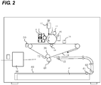
- FIG. 2 is a schematic diagram showing the configuration of the image forming apparatus according to this embodiment.
- the image forming apparatus of this embodiment includes four image processing units IP according to yellow, magenta, cyan and black, respectively.
- the four image forming apparatuses are of the same structure. Therefore, in FIG. 2 , the other three image processing units IP are omitted.
- each image processing unit IP a laser beam according to image information is irradiated from the scanner 12 on the photosensitive drum 1 (image bearing member) which is charged by charging roller 11.
- the electrostatic latent image is developed as a toner image of each color with using toner of each color.
- the developed toner image of each color is primarily transferred on the intermediate transfer belt 51 so as to overlap the toner images of the other colors by the primary transfer roller 14. Transfer residual toner remaining on the photosensitive drum 1 after the primary transfer is removed by the cleaning device 15.
- the sheet P stored in the sheet cassette 60 is conveyed to the secondary transfer portion T2 by the pickup roller 61, the conveying roller 62 and the registration roller 41.
- the secondary transfer portion T2 is a nip portion where the intermediate transfer belt 51 is nipped by the secondary transfer inner roller 39 and the secondary transfer outer roller 40.
- the toner image is secondarily transferred to the sheet P at the secondary transfer portion T2.
- the sheet P is discharged to the outside of the image forming apparatus. Transfer residual toner remaining on the intermediate transfer belt 51 after the secondary transfer, is removed by the cleaning device 50.
- FIG. 1 is a schematic diagram showing the configuration of the image processing unit IP.
- the developing device 2 includes the developing chamber 212, the stirring chamber 211.
- the developing chamber 212 and the stirring chamber 211 are partitioned by the partition wall 213 extending in the vertical direction.
- the developing device 2 uses a two-component developer composed of magnetic carrier and non-magnetic toner.
- the developing sleeve 232 of non-magnetic type is provided in the developing chamber 212.
- the magnet 231 of the 5-pole type is fixedly disposed in the developing chamber 212.
- the first conveying screw 222 is placed in the developing chamber 212. The first conveying screw 222 stirs and conveys the developer in the developing chamber 212.
- the second conveying screw 221 In the stirring chamber 211, the second conveying screw 221 is placed.
- the second conveying screw 221 stirs and conveys the toner for replenishment supplied from the toner bottle 8 and the developer already stored in the developing device 2, thereby the toner density of the developer is uniformed.
- the inductance sensor (toner density detecting means) 26 is provided in the stirring chamber 221.
- the inductance sensor 26 detects a toner density (TD ratio) of the developer.
- the developer moves from the stirring chamber 211 to the developing chamber 212 through developer passages (not shown) provided at both ends of the partition wall 213.
- the developing sleeve 232, the first conveying screw 222 and the second conveying screw 221 are driven by the development driving motor 27.
- the developer in the developing device 2 is restrained by magnetic force of the magnetic draw-up pole N3 and conveyed by rotation of the developing sleeve 232.
- the developer is fully restrained by the magnetic cut pole S2 and the thickness of the developer is regulated by the developer regulating blade 25.
- the developer is conveyed to a developing region facing the photosensitive drum 1 by rotation of the developing sleeve 232 and the conveying magnetic pole N1. Forming a magnetic brush by the magnetic developing pole S1 in the developing region, only the toner is transferred to the electrostatic latent image on the photosensitive drum 1 by the developing bias applied to the developing sleeve 232, thereby the toner image corresponding to the electrostatic latent image is formed on the photosensitive drum 1.
- FIG. 3 is a block diagram of the toner bottle 8.
- the lower conveying screw 82 supplies the toner stored in the toner bottle 8 to the developing device 2 through supply opening 85.
- the upper conveying screw 81 conveys the toner stored at the upper portion.
- the upper conveying screw 81 and the lower conveying screw 82 are rotated by the supply motor 73.
- the upper conveying screw 81, the lower conveying screw 82 and the supply motor 73 constitutes toner supply means.
- rotation of the supply motor 73 is detected in precision of the unit of one rotation of the screw.
- the CPU 101 of the control unit 100 drives the supply motor 73 such that the supply motor 73 rotates in a predetermined number of rotations.
- the toner bottle sensor (exchange detecting means) 86 is disposed, which determines whether the toner bottle 8 is present nor not.
- control for supplying toner to the developing device 2 from the toner bottle 8 is perfumed by the control unit 100.
- a toner density of the developer and an image density are controlled to be constant as possible.
- the control unit 100 decides whether the image forming operation is immediately allowed or not based on a detection result of the toner bottle sensor 86 (replacement detecting unit) after prohibiting the image forming operation based on a detection result of the inductance sensor (remaining amount detecting unit) 26.
- a supply restricting mode is performed, which restricts more an amount of the toner supply in the predetermined initial period after allowance than the normal mode.
- the toner supply amount M(N) of the Nth sheet is calculated (decided) from the following equation 3 using the video count supply amount M_Vc(N) calculated from the following Equation 1 and the inductance supply amount M_Indc(N) calculated from the following equation 2.
- the toner supply control is performed based on the number of rotations B of the supply motor 73 calculated from the following equation 4.
- M _ Vc N Vc ⁇ A _ Vc
- the video count value Vc is calculated from the image information of the Nth output.
- M _ Indc N TD _ target ⁇ TD _ Indc N ⁇ 1 ⁇ A _ Indc
- M_Indc 300mg when TD_Indc is lower than TD_target by a value larger than or equal to 1% (TD_target-TD_Indc ⁇ 1%).
- A_Indc 300 is recorded is to make the TD ratio stably transition even in an image having a high toner consumption with a high image ratio.
- M N M _ Vc N + M _ Indc N + M _ remain N ⁇ 1
- M_remain(N-1) is a residue supply amount which has not been supplied at the previous (N-1)th sheet.
- the amount T to be supplied to the developing device 2 while the lower toner conveying screw 82 makes one rotation, is stored in the ROM 102 beforehand.
- the decimals of B are omitted and only the integer part is calculated.
- the supply motor 73 is rotated by the number of rotations B calculated by Equation 4 at the Nth sheet.
- the maximum value of B is set to 5 and the remaining supply amount M_remain which has not been supplied, calculated by the following Equation 5 is supplied at the next toner supply.
- M _ remain M N ⁇ B ⁇ T
- the apparatus can be constructed such that a toner density in the developing device 2 is detected based on a density measuring patch provided on the photosensitive drum and that the toner supply control is performed based on the detection result.
- the toner bottle replacement instruction "Please replace the toner bottle” is displayed on the display unit 300 and the image forming operation is prohibited.
- the remaining supply amount M (remain) is set to 0 and the history of the past is reset.
- the emptiness judgment of the toner bottle 8 can be performed such that the toner bottle 8 is determined to be empty when the detection result does not change after tonner is supplied by driving the supply motor 73 and the development driving motor 27.
- the toner bottle replacement instruction In the state where the toner bottle replacement instruction is displayed on the display device 300, it is determined whether or not the toner bottle has been replaced based on a signal of the toner bottle sensor 86. In particular, in the state where the toner bottle replacement instruction is displayed on the display device 300, the absence of the toner bottle 8 is detected when the toner bottle 8 is pulled out once. Thereafter it is determined that the toner bottle 8 has been replaced when the present of the toner bottle 8 is detected again after the toner bottle 8 is inserted.
- the exchange of the toner bottle 8 may be determined based on a signal value of a circuit board attached to the toner bottle 8, by which whether the toner bottle 8 is new or not is judged.
- the circuit board may include a resistor which can be burned out when energized. Also, the determination of replacement of the toner bottle 8 is not limited to the above structures and it can be realized by conventional detection methods.
- the emptiness judgment of the toner bottle 8 is performed by using the inductance sensor (remaining amount detecting unit) 26 and by determining based on an inductance output value of the inductance sensor 26.
- the emptiness judgment is not limited to the above structure and this can also be substituted by variety of known toner remaining amount detecting methods.
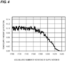
- FIG. 4 is a graph showing transition of a toner supply amount immediately before the toner bottle 8 becomes empty.
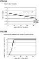
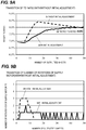
- FIG. 5A is a graph showing transition of the TD ratio immediately before the toner bottle 8 becomes empty on the condition of 5% image ratio.
- FIG. 5B is a graph showing transition in a number of rotations of the supply motor 73 immediately before the toner bottle 8 becomes empty on the condition of 5% image ratio.
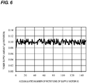
- FIG. 6 is a graph showing transition of a toner supply amount of the toner bottle 8 after replacement.
- FIG. 7A is a graph showing transition of the TD ratio after the toner bottle 8 is replaced on the condition of 5% image ratio.
- FIG. 7B is a graph showing transition in a number of rotations of the supply motor 73 after the toner bottle 8 is replaced on the condition of 5% image ratio.
- the toner supply amount after the toner bottle 8 is replaced returns generally to the values before the toner supply amount is decreased although it fluctuates a little. Therefore, a large amount of toner is supplied to the developing device 2 and the TD ratio detected by the inductance sensor 26 is rapidly increased on and after the fifth sheet where the supply toner reaches the inductance sensor 26, greatly exceeding 8% which is the target TD ratio (target value).
- the toner bottle initial period is provided.
- the coefficient (A_Indc_init) for calculating the inductance supply amount M_Indc which is less than the normal coefficient (A_Indc) is used.
- the coefficient A_Indc_init of the toner bottle initial period 100mg.
- the inductance supply amount M_Indc(N) in the toner bottle initial period is calculated by the Equation 6 below in place of the Equation 2.
- M _ Indc N TD _ target ⁇ TD _ Indc N ⁇ 1 ⁇ A _ Indc _ init
- the release timing of the toner bottle initial period is when the difference value between the detection result (TD ratio) of the inductance sensor 26 and the target TD ratio becomes within a predetermined range.
- the release timing of the toner bottle initial period is when the TD ratio (TD_Indc) detected at the Nth sheet gets to satisfy the expression TD_target-TD_Indc(N) ⁇ 0.1(%).
- the coefficient A_Indc_init is returned to the coefficient A_Indc.
- the present invention is not limited to 0.1(%) in the above expression and it may be other values in consideration of the TD ratio transition.
- the release timing of the toner bottle initial period may be when the predetermined time lapses or when image forming is performed for the predetermined number of sheets.
- the release timing of the toner bottle initial period may be when the predetermined amount of toner is supplied and the toner bottle initial period may be released when the accumulated number of rotations of the supply motor 73 exceeds a predetermined value after it is determined that the toner bottle 8 has been replaced.
- the toner bottle initial period may be released after the toner density recovery sequence for recovering the TD ratio is performed when the TD ratio is less than the target TD ratio by a value larger than or equal to a predetermined value after a predetermined period lapses after it is determined that the toner bottle 8 has been replaced.
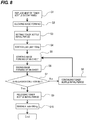
- FIG.8 is a flowchart showing the toner supply control in the present embodiment.
- the image forming is allowed (S2).
- the toner bottle initial period is set (S3) and the coefficient, which is used for calculating the inductor supply amount M_Indc, is changed from the A_Indc to A_Indc_init (S4).
- the image formation for the Nth sheet is started and after the completion of the image formation for the Nth sheet, whether the toner bottle initial period is released or not is determined (S7).
- the setting of the toner bottle initial period is continued (S8) and the sequence returns to S5.
- the toner bottle initial period is released (S9) and the coefficient to be used for calculating the inductance supply amount M_Indc is changed from A_Indc to A_Indc_init (S10). Then, the toner supply control after the toner bottle has been exchanged is finished and the sequence returns to the normal toner supply control.
- FIG. 9A is a graph showing transition of the TD ratio after replacement of the toner bottle on the condition of 5% image ratio according to the first embodiment.
- FIG. 9B is a graph showing transition in a number of rotations of the supply motor 73 after replacement of the toner bottle on the condition of 5% image ratio according to the first embodiment.
- the broken line represents the toner supply control without compensation (adjustment) by the toner bottle initial period and the solid line represents the toner supply control with compensation by the toner bottle initial period of the present embodiment.
- the toner supply amount is lowered than the normal toner supply amount.
- the transition of the toner supply count (a number of rotations B of the supply motor 73) becomes gentle and an increase in TD ratio also becomes gentle.
- the TD ratio does not greatly exceed the target TD ratio. Therefore, according to the present embodiment, transition of the TD ratio after replacement of the toner bottle becomes gentle and the level of density fluctuation can be reduced.
- the coefficient for use in calculating the inductance supply amount M_Indc in the toner bottle initial period one kind of coefficient is used.
- two kinds of coefficients are provided, which are used to calculate the inductance supply amount M_Indc in the toner bottle initial period and one of the two kinds of the coefficient is selected according to the magnitude relation of TD_target and TD_Indc(N-1).
- TD_target ⁇ TD_Indc of (N-1) that is if the TD ratio is smaller than the target value
- A_Indc and A_Indc_init are used.
- IC_Indc and C_Indc_init are used.
- the two kinds of coefficients are used and A_Indc_init is made smaller than the other coefficient.
- transition of the TD ratio after replacement of the toner bottle becomes gentle when the TD ratio is lowered than the target value and the level of density fluctuation is suppressed.
- the TD ratio does not exceed the target value (TD_target ⁇ TD_Indc(N-1)), however, TD ratio exceeds the target value depending on the conditions.
- the values A_Indc, A_Indc_init, C_Indc and C_Indc_init are not limited to the above values. Other values can be used as long as transition of the TD ratio becomes stricte when the TD ratio is smaller than the target value and the toner supply from the toner bottle 8 is suppressed when the TD ratio is larger than the target value. As for changing the value of C_Indc_init while observing the stability of the TD ratio, it is not limited.
- FIG. 10 is a flowchart showing the toner supply control in the present embodiment. As shown in FIG. 10 , in this embodiment, the operations of the selection of the coefficients to be used according to the magnitude relation of TD_target and TD_Indc(N-1) are added to S4, S10 of the flowchart of FIG 8 . Other steps are the same as the first embodiment.
- this embodiment has the following configuration. That is, an upper limit (maximum value) of inductance supply amount M_Indc of the first and second embodiments is set. Thereby, even if the difference value between TD_target and TD_Indc(N-1) is large, inductor supply amount M_Indc does not become too large. Therefore, according to the present embodiment, transition of the TD ratio after replacement of the toner bottle becomes gentle and the level of density fluctuation can be suppressed like the first and second embodiments.
- the upper limit of the inductance supply amount M_Indc is set to 100mg but it may be set to other value in accordance with transition of the TD ratio.
- the upper limit of the suppressing mode is made to be smaller than the upper limit of the normal mode. Thereby, accidental over-supply can be suppressed.
- the difference value between TD_target and TD_Indc(N-1) can be decreased and the inductance supply amount M_Indc can be reduced accordingly. Therefore, according to the present embodiment, transition of the TD ratio after replacement of the toner bottle becomes gentle and the level of density fluctuation can be reduced like the first, second and third embodiments.
- transition of the TD ratio after replacement of the toner bottle becomes gentle, the significant excess of the TD ratio from the target value can be suppressed and the level of density fluctuation can be suppressed.
- An image forming apparatus which prohibits an image forming operation based on a detection result of a remaining amount detecting means (26), thereafter immediately allows the image forming operation based on a detection result of a replacement detecting means (86), performs a supply restriction mode which restricts a toner supply amount such that a toner supply amount in a predetermined initial period after allowance of an image forming is smaller than a normal mode in a case where a detection result of a toner density detecting means (26) and a target value are under same conditions, respectively.
Landscapes
- Physics & Mathematics (AREA)
- General Physics & Mathematics (AREA)
- Dry Development In Electrophotography (AREA)
- Control Or Security For Electrophotography (AREA)
Applications Claiming Priority (1)
| Application Number | Priority Date | Filing Date | Title |
|---|---|---|---|
| JP2013221819A JP6289028B2 (ja) | 2013-10-25 | 2013-10-25 | 画像形成装置 |
Publications (2)
| Publication Number | Publication Date |
|---|---|
| EP2866096A1 EP2866096A1 (en) | 2015-04-29 |
| EP2866096B1 true EP2866096B1 (en) | 2020-06-24 |
Family
ID=51794764
Family Applications (1)
| Application Number | Title | Priority Date | Filing Date |
|---|---|---|---|
| EP14189997.1A Active EP2866096B1 (en) | 2013-10-25 | 2014-10-23 | Image forming apparatus |
Country Status (4)
| Country | Link |
|---|---|
| US (1) | US9285704B2 (enExample) |
| EP (1) | EP2866096B1 (enExample) |
| JP (1) | JP6289028B2 (enExample) |
| CN (1) | CN104570659B (enExample) |
Families Citing this family (5)
| Publication number | Priority date | Publication date | Assignee | Title |
|---|---|---|---|---|
| JP6391220B2 (ja) * | 2013-08-19 | 2018-09-19 | キヤノン株式会社 | 画像形成装置 |
| JP6680241B2 (ja) * | 2017-02-21 | 2020-04-15 | 京セラドキュメントソリューションズ株式会社 | 画像形成装置 |
| JP6984219B2 (ja) * | 2017-08-04 | 2021-12-17 | 株式会社リコー | 現像剤補給制御システム、画像形成装置、及び現像剤補給制御方法 |
| JP7336196B2 (ja) * | 2019-01-09 | 2023-08-31 | キヤノン株式会社 | 画像形成装置 |
| CN111546795B (zh) * | 2019-02-12 | 2022-05-13 | 珠海艾派克微电子有限公司 | 打印控制方法、耗材芯片和图像形成系统 |
Citations (2)
| Publication number | Priority date | Publication date | Assignee | Title |
|---|---|---|---|---|
| JPH10207214A (ja) * | 1997-01-20 | 1998-08-07 | Ricoh Co Ltd | 画像形成装置 |
| JP2007199364A (ja) * | 2006-01-26 | 2007-08-09 | Kyocera Mita Corp | 画像形成装置 |
Family Cites Families (7)
| Publication number | Priority date | Publication date | Assignee | Title |
|---|---|---|---|---|
| US5585899A (en) | 1996-02-02 | 1996-12-17 | Xerox Corporation | Multicontainer toner dispensing apparatus |
| JP3576769B2 (ja) | 1997-09-22 | 2004-10-13 | 株式会社リコー | 画像形成装置 |
| JP2005062848A (ja) | 2003-07-29 | 2005-03-10 | Canon Inc | 画像形成装置及びその制御方法 |
| JP4955963B2 (ja) * | 2005-08-31 | 2012-06-20 | キヤノン株式会社 | 画像形成装置 |
| JP2008209795A (ja) | 2007-02-27 | 2008-09-11 | Kyocera Mita Corp | 画像形成装置 |
| JP5332336B2 (ja) * | 2008-06-20 | 2013-11-06 | 株式会社リコー | トナー補給装置及び画像形成装置 |
| JP5605694B2 (ja) * | 2010-08-03 | 2014-10-15 | 株式会社リコー | トナー補給方法、現像装置、プロセスユニットおよび画像形成装置 |
-
2013
- 2013-10-25 JP JP2013221819A patent/JP6289028B2/ja not_active Expired - Fee Related
-
2014
- 2014-10-17 US US14/517,323 patent/US9285704B2/en active Active
- 2014-10-21 CN CN201410560188.5A patent/CN104570659B/zh active Active
- 2014-10-23 EP EP14189997.1A patent/EP2866096B1/en active Active
Patent Citations (2)
| Publication number | Priority date | Publication date | Assignee | Title |
|---|---|---|---|---|
| JPH10207214A (ja) * | 1997-01-20 | 1998-08-07 | Ricoh Co Ltd | 画像形成装置 |
| JP2007199364A (ja) * | 2006-01-26 | 2007-08-09 | Kyocera Mita Corp | 画像形成装置 |
Also Published As
| Publication number | Publication date |
|---|---|
| JP2015084015A (ja) | 2015-04-30 |
| US20150117880A1 (en) | 2015-04-30 |
| US9285704B2 (en) | 2016-03-15 |
| CN104570659B (zh) | 2020-03-17 |
| CN104570659A (zh) | 2015-04-29 |
| EP2866096A1 (en) | 2015-04-29 |
| JP6289028B2 (ja) | 2018-03-07 |
Similar Documents
| Publication | Publication Date | Title |
|---|---|---|
| US20250258455A1 (en) | Information processing apparatus, method of controlling information processing apparatus, and image forming apparatus | |
| EP2866096B1 (en) | Image forming apparatus | |
| US7619791B2 (en) | Image forming method and image forming device | |
| EP3032337A1 (en) | Image forming apparatus | |
| EP2913716A2 (en) | Image forming apparatus | |
| US9122196B2 (en) | Image forming apparatus | |
| JP2015152894A (ja) | 画像形成装置 | |
| US9946191B2 (en) | Image forming apparatus | |
| EP3032340A1 (en) | Image forming apparatus | |
| JP2009192768A (ja) | 画像形成装置、および画像形成装置の制御方法 | |
| JP2007052213A (ja) | 現像装置およびトナー濃度制御方法 | |
| JP2010204519A (ja) | 画像濃度制御方法及び画像形成装置 | |
| JP2015125159A (ja) | 画像形成装置 | |
| EP2887146B1 (en) | Image forming apparatus and method for controlling image forming apparatus | |
| JP2019148771A (ja) | 画像形成装置 | |
| JP2009192707A (ja) | 現像装置、画像形成装置及び画像形成方法 | |
| JP6556276B2 (ja) | 画像形成装置 | |
| JP2001296732A (ja) | 画像形成装置 | |
| JP2021086061A (ja) | 画像形成装置 | |
| JP2008158246A (ja) | 画像形成装置 | |
| US12429796B2 (en) | Image forming apparatus | |
| EP3376301A1 (en) | Image forming apparatus | |
| JP2021086062A (ja) | 画像形成装置 | |
| JP6938551B2 (ja) | 画像形成装置 | |
| JP6863327B2 (ja) | 画像形成装置 |
Legal Events
| Date | Code | Title | Description |
|---|---|---|---|
| PUAI | Public reference made under article 153(3) epc to a published international application that has entered the european phase |
Free format text: ORIGINAL CODE: 0009012 |
|
| 17P | Request for examination filed |
Effective date: 20141023 |
|
| AK | Designated contracting states |
Kind code of ref document: A1 Designated state(s): AL AT BE BG CH CY CZ DE DK EE ES FI FR GB GR HR HU IE IS IT LI LT LU LV MC MK MT NL NO PL PT RO RS SE SI SK SM TR |
|
| AX | Request for extension of the european patent |
Extension state: BA ME |
|
| R17P | Request for examination filed (corrected) |
Effective date: 20151029 |
|
| RBV | Designated contracting states (corrected) |
Designated state(s): AL AT BE BG CH CY CZ DE DK EE ES FI FR GB GR HR HU IE IS IT LI LT LU LV MC MK MT NL NO PL PT RO RS SE SI SK SM TR |
|
| STAA | Information on the status of an ep patent application or granted ep patent |
Free format text: STATUS: EXAMINATION IS IN PROGRESS |
|
| 17Q | First examination report despatched |
Effective date: 20190327 |
|
| GRAP | Despatch of communication of intention to grant a patent |
Free format text: ORIGINAL CODE: EPIDOSNIGR1 |
|
| STAA | Information on the status of an ep patent application or granted ep patent |
Free format text: STATUS: GRANT OF PATENT IS INTENDED |
|
| INTG | Intention to grant announced |
Effective date: 20200103 |
|
| RIN1 | Information on inventor provided before grant (corrected) |
Inventor name: OKADA, NORIYUKI |
|
| GRAS | Grant fee paid |
Free format text: ORIGINAL CODE: EPIDOSNIGR3 |
|
| GRAA | (expected) grant |
Free format text: ORIGINAL CODE: 0009210 |
|
| STAA | Information on the status of an ep patent application or granted ep patent |
Free format text: STATUS: THE PATENT HAS BEEN GRANTED |
|
| AK | Designated contracting states |
Kind code of ref document: B1 Designated state(s): AL AT BE BG CH CY CZ DE DK EE ES FI FR GB GR HR HU IE IS IT LI LT LU LV MC MK MT NL NO PL PT RO RS SE SI SK SM TR |
|
| REG | Reference to a national code |
Ref country code: GB Ref legal event code: FG4D |
|
| REG | Reference to a national code |
Ref country code: CH Ref legal event code: EP |
|
| REG | Reference to a national code |
Ref country code: AT Ref legal event code: REF Ref document number: 1284497 Country of ref document: AT Kind code of ref document: T Effective date: 20200715 |
|
| REG | Reference to a national code |
Ref country code: DE Ref legal event code: R096 Ref document number: 602014066926 Country of ref document: DE |
|
| REG | Reference to a national code |
Ref country code: IE Ref legal event code: FG4D |
|
| PG25 | Lapsed in a contracting state [announced via postgrant information from national office to epo] |
Ref country code: GR Free format text: LAPSE BECAUSE OF FAILURE TO SUBMIT A TRANSLATION OF THE DESCRIPTION OR TO PAY THE FEE WITHIN THE PRESCRIBED TIME-LIMIT Effective date: 20200925 Ref country code: LT Free format text: LAPSE BECAUSE OF FAILURE TO SUBMIT A TRANSLATION OF THE DESCRIPTION OR TO PAY THE FEE WITHIN THE PRESCRIBED TIME-LIMIT Effective date: 20200624 Ref country code: NO Free format text: LAPSE BECAUSE OF FAILURE TO SUBMIT A TRANSLATION OF THE DESCRIPTION OR TO PAY THE FEE WITHIN THE PRESCRIBED TIME-LIMIT Effective date: 20200924 Ref country code: FI Free format text: LAPSE BECAUSE OF FAILURE TO SUBMIT A TRANSLATION OF THE DESCRIPTION OR TO PAY THE FEE WITHIN THE PRESCRIBED TIME-LIMIT Effective date: 20200624 Ref country code: SE Free format text: LAPSE BECAUSE OF FAILURE TO SUBMIT A TRANSLATION OF THE DESCRIPTION OR TO PAY THE FEE WITHIN THE PRESCRIBED TIME-LIMIT Effective date: 20200624 |
|
| REG | Reference to a national code |
Ref country code: LT Ref legal event code: MG4D |
|
| PG25 | Lapsed in a contracting state [announced via postgrant information from national office to epo] |
Ref country code: RS Free format text: LAPSE BECAUSE OF FAILURE TO SUBMIT A TRANSLATION OF THE DESCRIPTION OR TO PAY THE FEE WITHIN THE PRESCRIBED TIME-LIMIT Effective date: 20200624 Ref country code: BG Free format text: LAPSE BECAUSE OF FAILURE TO SUBMIT A TRANSLATION OF THE DESCRIPTION OR TO PAY THE FEE WITHIN THE PRESCRIBED TIME-LIMIT Effective date: 20200924 Ref country code: LV Free format text: LAPSE BECAUSE OF FAILURE TO SUBMIT A TRANSLATION OF THE DESCRIPTION OR TO PAY THE FEE WITHIN THE PRESCRIBED TIME-LIMIT Effective date: 20200624 Ref country code: HR Free format text: LAPSE BECAUSE OF FAILURE TO SUBMIT A TRANSLATION OF THE DESCRIPTION OR TO PAY THE FEE WITHIN THE PRESCRIBED TIME-LIMIT Effective date: 20200624 |
|
| REG | Reference to a national code |
Ref country code: NL Ref legal event code: MP Effective date: 20200624 |
|
| REG | Reference to a national code |
Ref country code: AT Ref legal event code: MK05 Ref document number: 1284497 Country of ref document: AT Kind code of ref document: T Effective date: 20200624 |
|
| PG25 | Lapsed in a contracting state [announced via postgrant information from national office to epo] |
Ref country code: AL Free format text: LAPSE BECAUSE OF FAILURE TO SUBMIT A TRANSLATION OF THE DESCRIPTION OR TO PAY THE FEE WITHIN THE PRESCRIBED TIME-LIMIT Effective date: 20200624 Ref country code: NL Free format text: LAPSE BECAUSE OF FAILURE TO SUBMIT A TRANSLATION OF THE DESCRIPTION OR TO PAY THE FEE WITHIN THE PRESCRIBED TIME-LIMIT Effective date: 20200624 |
|
| PG25 | Lapsed in a contracting state [announced via postgrant information from national office to epo] |
Ref country code: AT Free format text: LAPSE BECAUSE OF FAILURE TO SUBMIT A TRANSLATION OF THE DESCRIPTION OR TO PAY THE FEE WITHIN THE PRESCRIBED TIME-LIMIT Effective date: 20200624 Ref country code: SM Free format text: LAPSE BECAUSE OF FAILURE TO SUBMIT A TRANSLATION OF THE DESCRIPTION OR TO PAY THE FEE WITHIN THE PRESCRIBED TIME-LIMIT Effective date: 20200624 Ref country code: EE Free format text: LAPSE BECAUSE OF FAILURE TO SUBMIT A TRANSLATION OF THE DESCRIPTION OR TO PAY THE FEE WITHIN THE PRESCRIBED TIME-LIMIT Effective date: 20200624 Ref country code: IT Free format text: LAPSE BECAUSE OF FAILURE TO SUBMIT A TRANSLATION OF THE DESCRIPTION OR TO PAY THE FEE WITHIN THE PRESCRIBED TIME-LIMIT Effective date: 20200624 Ref country code: CZ Free format text: LAPSE BECAUSE OF FAILURE TO SUBMIT A TRANSLATION OF THE DESCRIPTION OR TO PAY THE FEE WITHIN THE PRESCRIBED TIME-LIMIT Effective date: 20200624 Ref country code: RO Free format text: LAPSE BECAUSE OF FAILURE TO SUBMIT A TRANSLATION OF THE DESCRIPTION OR TO PAY THE FEE WITHIN THE PRESCRIBED TIME-LIMIT Effective date: 20200624 Ref country code: PT Free format text: LAPSE BECAUSE OF FAILURE TO SUBMIT A TRANSLATION OF THE DESCRIPTION OR TO PAY THE FEE WITHIN THE PRESCRIBED TIME-LIMIT Effective date: 20201026 Ref country code: ES Free format text: LAPSE BECAUSE OF FAILURE TO SUBMIT A TRANSLATION OF THE DESCRIPTION OR TO PAY THE FEE WITHIN THE PRESCRIBED TIME-LIMIT Effective date: 20200624 |
|
| PG25 | Lapsed in a contracting state [announced via postgrant information from national office to epo] |
Ref country code: PL Free format text: LAPSE BECAUSE OF FAILURE TO SUBMIT A TRANSLATION OF THE DESCRIPTION OR TO PAY THE FEE WITHIN THE PRESCRIBED TIME-LIMIT Effective date: 20200624 Ref country code: SK Free format text: LAPSE BECAUSE OF FAILURE TO SUBMIT A TRANSLATION OF THE DESCRIPTION OR TO PAY THE FEE WITHIN THE PRESCRIBED TIME-LIMIT Effective date: 20200624 Ref country code: IS Free format text: LAPSE BECAUSE OF FAILURE TO SUBMIT A TRANSLATION OF THE DESCRIPTION OR TO PAY THE FEE WITHIN THE PRESCRIBED TIME-LIMIT Effective date: 20201024 |
|
| REG | Reference to a national code |
Ref country code: DE Ref legal event code: R097 Ref document number: 602014066926 Country of ref document: DE |
|
| PG25 | Lapsed in a contracting state [announced via postgrant information from national office to epo] |
Ref country code: DK Free format text: LAPSE BECAUSE OF FAILURE TO SUBMIT A TRANSLATION OF THE DESCRIPTION OR TO PAY THE FEE WITHIN THE PRESCRIBED TIME-LIMIT Effective date: 20200624 |
|
| PLBE | No opposition filed within time limit |
Free format text: ORIGINAL CODE: 0009261 |
|
| STAA | Information on the status of an ep patent application or granted ep patent |
Free format text: STATUS: NO OPPOSITION FILED WITHIN TIME LIMIT |
|
| REG | Reference to a national code |
Ref country code: CH Ref legal event code: PL |
|
| 26N | No opposition filed |
Effective date: 20210325 |
|
| PG25 | Lapsed in a contracting state [announced via postgrant information from national office to epo] |
Ref country code: MC Free format text: LAPSE BECAUSE OF FAILURE TO SUBMIT A TRANSLATION OF THE DESCRIPTION OR TO PAY THE FEE WITHIN THE PRESCRIBED TIME-LIMIT Effective date: 20200624 Ref country code: LU Free format text: LAPSE BECAUSE OF NON-PAYMENT OF DUE FEES Effective date: 20201023 |
|
| REG | Reference to a national code |
Ref country code: BE Ref legal event code: MM Effective date: 20201031 |
|
| PG25 | Lapsed in a contracting state [announced via postgrant information from national office to epo] |
Ref country code: FR Free format text: LAPSE BECAUSE OF NON-PAYMENT OF DUE FEES Effective date: 20201031 |
|
| PG25 | Lapsed in a contracting state [announced via postgrant information from national office to epo] |
Ref country code: BE Free format text: LAPSE BECAUSE OF NON-PAYMENT OF DUE FEES Effective date: 20201031 Ref country code: CH Free format text: LAPSE BECAUSE OF NON-PAYMENT OF DUE FEES Effective date: 20201031 Ref country code: SI Free format text: LAPSE BECAUSE OF FAILURE TO SUBMIT A TRANSLATION OF THE DESCRIPTION OR TO PAY THE FEE WITHIN THE PRESCRIBED TIME-LIMIT Effective date: 20200624 Ref country code: LI Free format text: LAPSE BECAUSE OF NON-PAYMENT OF DUE FEES Effective date: 20201031 |
|
| PG25 | Lapsed in a contracting state [announced via postgrant information from national office to epo] |
Ref country code: IE Free format text: LAPSE BECAUSE OF NON-PAYMENT OF DUE FEES Effective date: 20201023 |
|
| PG25 | Lapsed in a contracting state [announced via postgrant information from national office to epo] |
Ref country code: TR Free format text: LAPSE BECAUSE OF FAILURE TO SUBMIT A TRANSLATION OF THE DESCRIPTION OR TO PAY THE FEE WITHIN THE PRESCRIBED TIME-LIMIT Effective date: 20200624 Ref country code: MT Free format text: LAPSE BECAUSE OF FAILURE TO SUBMIT A TRANSLATION OF THE DESCRIPTION OR TO PAY THE FEE WITHIN THE PRESCRIBED TIME-LIMIT Effective date: 20200624 Ref country code: CY Free format text: LAPSE BECAUSE OF FAILURE TO SUBMIT A TRANSLATION OF THE DESCRIPTION OR TO PAY THE FEE WITHIN THE PRESCRIBED TIME-LIMIT Effective date: 20200624 |
|
| PG25 | Lapsed in a contracting state [announced via postgrant information from national office to epo] |
Ref country code: MK Free format text: LAPSE BECAUSE OF FAILURE TO SUBMIT A TRANSLATION OF THE DESCRIPTION OR TO PAY THE FEE WITHIN THE PRESCRIBED TIME-LIMIT Effective date: 20200624 |
|
| PGFP | Annual fee paid to national office [announced via postgrant information from national office to epo] |
Ref country code: GB Payment date: 20250923 Year of fee payment: 12 |
|
| PGFP | Annual fee paid to national office [announced via postgrant information from national office to epo] |
Ref country code: DE Payment date: 20250923 Year of fee payment: 12 |