EP2865872B1 - Dispositif de commande de moteur à combustion interne - Google Patents
Dispositif de commande de moteur à combustion interne Download PDFInfo
- Publication number
- EP2865872B1 EP2865872B1 EP12879833.7A EP12879833A EP2865872B1 EP 2865872 B1 EP2865872 B1 EP 2865872B1 EP 12879833 A EP12879833 A EP 12879833A EP 2865872 B1 EP2865872 B1 EP 2865872B1
- Authority
- EP
- European Patent Office
- Prior art keywords
- learning
- value
- map
- control
- ignition timing
- Prior art date
- Legal status (The legal status is an assumption and is not a legal conclusion. Google has not performed a legal analysis and makes no representation as to the accuracy of the status listed.)
- Not-in-force
Links
- 238000002485 combustion reaction Methods 0.000 title claims description 130
- 239000000446 fuel Substances 0.000 claims description 243
- 238000012937 correction Methods 0.000 claims description 140
- 238000002347 injection Methods 0.000 claims description 134
- 239000007924 injection Substances 0.000 claims description 134
- 230000005484 gravity Effects 0.000 claims description 83
- 230000006870 function Effects 0.000 claims description 57
- 230000007423 decrease Effects 0.000 claims description 56
- 238000011156 evaluation Methods 0.000 claims description 43
- 230000003247 decreasing effect Effects 0.000 claims description 20
- QVGXLLKOCUKJST-UHFFFAOYSA-N atomic oxygen Chemical compound [O] QVGXLLKOCUKJST-UHFFFAOYSA-N 0.000 claims description 17
- 230000003111 delayed effect Effects 0.000 claims description 17
- 239000001301 oxygen Substances 0.000 claims description 17
- 229910052760 oxygen Inorganic materials 0.000 claims description 17
- 230000007704 transition Effects 0.000 claims description 11
- 238000004364 calculation method Methods 0.000 description 71
- 238000010586 diagram Methods 0.000 description 54
- 238000012545 processing Methods 0.000 description 35
- 230000008859 change Effects 0.000 description 29
- 230000003245 working effect Effects 0.000 description 23
- 239000000470 constituent Substances 0.000 description 22
- 230000000694 effects Effects 0.000 description 21
- 238000001514 detection method Methods 0.000 description 19
- 230000007246 mechanism Effects 0.000 description 10
- 238000000034 method Methods 0.000 description 10
- XLYOFNOQVPJJNP-UHFFFAOYSA-N water Substances O XLYOFNOQVPJJNP-UHFFFAOYSA-N 0.000 description 9
- 230000004043 responsiveness Effects 0.000 description 8
- 239000003054 catalyst Substances 0.000 description 7
- 239000007789 gas Substances 0.000 description 7
- 238000010438 heat treatment Methods 0.000 description 7
- 230000004044 response Effects 0.000 description 7
- 230000001133 acceleration Effects 0.000 description 5
- 101100409308 Neurospora crassa (strain ATCC 24698 / 74-OR23-1A / CBS 708.71 / DSM 1257 / FGSC 987) adv-1 gene Proteins 0.000 description 3
- 230000006866 deterioration Effects 0.000 description 3
- 238000012935 Averaging Methods 0.000 description 2
- 230000000052 comparative effect Effects 0.000 description 2
- 230000006835 compression Effects 0.000 description 2
- 238000007906 compression Methods 0.000 description 2
- 238000005259 measurement Methods 0.000 description 2
- 239000000203 mixture Substances 0.000 description 2
- 230000005856 abnormality Effects 0.000 description 1
- 238000004891 communication Methods 0.000 description 1
- 239000002826 coolant Substances 0.000 description 1
- 230000002950 deficient Effects 0.000 description 1
- 230000001934 delay Effects 0.000 description 1
- 238000013461 design Methods 0.000 description 1
- 238000007429 general method Methods 0.000 description 1
- 230000006872 improvement Effects 0.000 description 1
- 238000010992 reflux Methods 0.000 description 1
- 230000001360 synchronised effect Effects 0.000 description 1
- 238000011144 upstream manufacturing Methods 0.000 description 1
Images

Classifications
-
- F—MECHANICAL ENGINEERING; LIGHTING; HEATING; WEAPONS; BLASTING
- F02—COMBUSTION ENGINES; HOT-GAS OR COMBUSTION-PRODUCT ENGINE PLANTS
- F02D—CONTROLLING COMBUSTION ENGINES
- F02D41/00—Electrical control of supply of combustible mixture or its constituents
- F02D41/02—Circuit arrangements for generating control signals
- F02D41/14—Introducing closed-loop corrections
- F02D41/1401—Introducing closed-loop corrections characterised by the control or regulation method
- F02D41/1402—Adaptive control
-
- F—MECHANICAL ENGINEERING; LIGHTING; HEATING; WEAPONS; BLASTING
- F02—COMBUSTION ENGINES; HOT-GAS OR COMBUSTION-PRODUCT ENGINE PLANTS
- F02D—CONTROLLING COMBUSTION ENGINES
- F02D41/00—Electrical control of supply of combustible mixture or its constituents
- F02D41/24—Electrical control of supply of combustible mixture or its constituents characterised by the use of digital means
- F02D41/2406—Electrical control of supply of combustible mixture or its constituents characterised by the use of digital means using essentially read only memories
- F02D41/2409—Addressing techniques specially adapted therefor
- F02D41/2416—Interpolation techniques
-
- F—MECHANICAL ENGINEERING; LIGHTING; HEATING; WEAPONS; BLASTING
- F02—COMBUSTION ENGINES; HOT-GAS OR COMBUSTION-PRODUCT ENGINE PLANTS
- F02D—CONTROLLING COMBUSTION ENGINES
- F02D28/00—Programme-control of engines
-
- F—MECHANICAL ENGINEERING; LIGHTING; HEATING; WEAPONS; BLASTING
- F02—COMBUSTION ENGINES; HOT-GAS OR COMBUSTION-PRODUCT ENGINE PLANTS
- F02D—CONTROLLING COMBUSTION ENGINES
- F02D41/00—Electrical control of supply of combustible mixture or its constituents
- F02D41/24—Electrical control of supply of combustible mixture or its constituents characterised by the use of digital means
- F02D41/2406—Electrical control of supply of combustible mixture or its constituents characterised by the use of digital means using essentially read only memories
- F02D41/2425—Particular ways of programming the data
- F02D41/2429—Methods of calibrating or learning
- F02D41/2477—Methods of calibrating or learning characterised by the method used for learning
- F02D41/248—Methods of calibrating or learning characterised by the method used for learning using a plurality of learned values
Definitions
- the present invention relates to an internal combustion engine control device provided with a learning map of control parameters.
- Patent Literature 1 Japanese Patent Laid-Open No. 2009-046988
- an internal combustion engine control device provided with a learning map of control parameters is known. Learning values for correcting the control parameters are stored in each of grid points of the learning map, respectively.
- it is configured that, when the control parameter to be learned is acquired, four grid points located in the periphery of the acquired value are selected on the learning map, and the learning values at these four grid points are updated.
- the acquired value of the control parameter is weighted and then, reflected in the learning values of the grid points on the periphery, but the weighting at this time is set so that the closer a distance between the position of the acquired value and the grid point is, the larger the weighting becomes.
- US 2005/0085981 discloses a fast learn algorithm for quickly providing data to a data table and a controller. Existing data is considered, such that information gathered from prior events is not arbitrarily overwritten. An error is determined for a first data cell based on current operating conditions and the occurrence of an event. Weighting factors are then applied to data cells removed from the first data cell, such that some or all of the data cells in the data table can be populated based on the data input into the first data cell.
- the learning control is executed for the four learning values located in the periphery of the acquired value of the control parameter so that the closer to the acquired value the grid point is, the larger the weighting becomes.
- the learning values updated in one session of a learning operation is limited only to the four, and the learning value is not updated at a grid point away from the acquired value of the control parameter and thus, there is a problem that learning efficiency is low.
- the periphery of the grid point at which the learning value is not updated there is a concern of mis-learning.
- the present invention was made in order to solve the above-described problems and has an object to provide an internal combustion engine control device which can update the learning values at a large number of grid points in one session of the learning operation and can easily adjust learning characteristics (learning speed or efficiency) in a wide learning region.
- an internal combustion engine control device as defined in appended claim 1.
- a seventh aspect of the present invention further comprising:
- An eighth aspect of the present invention is a control device for internal combustion engine, comprising:
- a tenth aspect of the present invention further comprising:
- An eleventh aspect of the present invention further comprising:
- a twelfth aspect of the present invention further comprising:
- a thirteenth aspect of the present invention further comprising:
- the learning values at all the grid points can be appropriately updated while being weighted in accordance with a distance by performing one session of the learning operation.
- the learning values at all the grid points can be optimized quickly by the minimum number of learning times.
- these learning values can be compensated for by the learning operation at other positions. Therefore, regardless of a type of the control parameter, learning efficiency is improved, and reliability of the learning control can be improved.
- the learning speed or efficiency can be easily adjusted in a wide learning region. Furthermore, since consecutive averaging processing is executed each time the control parameter is acquired, an influence of disturbance (noises and the like) to the learning value can be removed. Moreover, since a calculation load of the learning value can be temporally distributed by the consecutive processing, the calculation load of the learning processing can be alleviated.
- the weight setting means can switch the weight decrease characteristic in accordance with each of a plurality of regions.
- a setting capable of a rapid change in the weight in a region requiring rapid learning for example, learning responsiveness and control efficiency can be improved, and an operation such as failsafe can be made stable.
- the calculation load in learning can be suppressed, and the learning map can be made smooth. Therefore, the weighting conforming to the entire learning map can be easily realized.
- responsiveness, a speed, efficiency and the like of the learning at all the grid points can be switched in accordance with the characteristics of the region to which the acquired value of the control parameter belongs.
- the third invention at a grid point at which a distance from a reference position is larger than a predetermined effective range, update of the learning value can be prohibited.
- the grid point at which the learning value is updated can be limited to the effective range, wasteful update of the learning value at the grid point with small learning effect can be avoided, and the calculation load of the learning processing can be alleviated.
- the weight can be smoothly changed in accordance with a distance from the position (reference position) of the acquired value of the control parameter. Therefore, the learning map can be made smooth, and deterioration of controllability caused by a rapid change in the learning value and the like can be suppressed. Moreover, the decrease characteristic of the weight can be changed in accordance with setting of standard deviation ⁇ of the Gaussian function, and the learning speed or efficiency can be easily adjusted in a wide learning region.
- the calculation load when the weight is calculated can be drastically reduced.
- the weight setting means by using a trigonometric function as the weight setting means, while the calculation load of the weight is decreased more than the Gaussian function, the weight can be reduced smoothly similarly to the case in which the Gaussian function is used.
- the seventh invention in a reliability evaluation value of each grid point of a reliability map, reliability of the learning value at the same grid point can be reflected. And by executing the weighted learning control of the reliability evaluation value, a reliability acquired value can be reflected in the reliability evaluation value at each grid point at the same degree of reflection as that when the acquired value of the control parameter is reflected in the learning value of each grid point. Therefore, the reliability of the learning value of each grid point can be efficiently calculated in one session of the learning operation. Moreover, if the learning value is used for various controls and the like, the reliability of the learning value can be evaluated on the basis of the reliability evaluation value of the corresponding grid point on the reliability map and appropriate corresponding control can be executed on the basis of the evaluation result.
- the weighted learning control is executed only when a combustion gravity center substantially matches a combustion gravity center target value, but since MBT can be efficiently learned at all the grid points of a MBT map in one session of the learning operation, even if the learning chances are fewer, learning can be made sufficiently.
- the more stable an operation state is when the ignition timing is acquired that is, the higher the reliability of the acquired value of the ignition timing is, the larger an update amount of the learning value can be.
- the operation state is unstable, the update amount of the learning value is set smaller, and the learning can be stopped or suppressed. As a result, learning in a steady operation can be promoted, and mis-learning in transition operation can be suppressed.
- an estimated value of the MBT can be acquired all the time, and thus, the learning value can be updated on the basis of this estimated value, and the learning chances can be increased.
- the learning value can be brought closer to the MBT quickly, and controllability of MBT control can be improved.
- MBT full-time learning means can reduce the weight and can decrease the update amount of the learning value. Therefore, a degree of reflection of the estimated value of the MBT in the learning value can be adjusted appropriately in accordance with a degree of reliability of the estimated value, and mis-learning can be suppressed.
- the eleventh invention in learning of the ignition timing, either of the MBT and TK ignition timing can be learned, and thus, the learning chances can be increased, and the ignition timing can be efficiently learned other than an MBT region. Moreover, since selecting means can select the ignition timing on an advanced angle side from the MBT learning value and a TK learning value, the ignition timing can be controlled to the advanced angle side as much as possible and operation performances and operation efficiency can be improved while occurrence of knocking is avoided.
- a boundary of a TK region can be made clear, and thus, mis-learning of the TK ignition timing in a region other than a TK region can be suppressed, and learning accuracy can be improved.
- the reliability map in the seventh invention can be applied to the eighth to twelfth inventions.
- reliability of the learning value of the ignition timing can be evaluated on the basis of the reliability evaluation value of the corresponding grid point on the reliability map, and appropriate corresponding control can be executed on the basis of the evaluation result.
- the fourteenth invention in calculation control of an in-cylinder air-fuel ratio, the same working effect as that in the first invention can be obtained.
- the in-cylinder air-fuel ratio calculated by an in-cylinder sensor has a large error caused by a change in the operation state and thus, practicability cannot be easily improved even by using a correction coefficient acquired by a prior-art learning method.
- the weighting learning control can quickly learn the correction coefficients of all the grid points of a correction map even if the learning chances are relatively fewer. Therefore, even if an error of the in-cylinder air-fuel ratio is large, this error can be appropriately corrected by the correction coefficient, and the calculation accuracy and practicability of the in-cylinder air-fuel ratio can be improved.
- the learning control of a fuel injection characteristic in the learning control of a fuel injection characteristic, the same working effect as that in the first invention can be obtained. Therefore, a change in the injection characteristic can be efficiently learned even in a small number of learning times, and accuracy of fuel injection control can be improved. Moreover, an actual injection amount can be calculated on the basis of an output of an in-cylinder pressure sensor, and learning can be executed on the basis of this actual injection amount and thus, even if an actual fuel injection amount cannot be detected, the learning control can be easily executed by using an existing sensor.
- the sixteenth invention in learning control of a correction coefficient for an airflow sensor, the same working effect as that in the first invention can be obtained. Therefore, the correction coefficient can be efficiently learned even in a small number of learning times, and calculation accuracy of an intake air amount can be improved.
- the seventeenth invention in learning control of a wall-surface fuel adhesion amount, the same working effect as that in the first invention can be obtained. Therefore, the wall-surface fuel adhesion amount can be efficiently learned even in a small number of learning times, and accuracy of fuel injection control can be improved.
- the eighteenth invention in learning control of valve timing, the same working effect as that in the first invention can be obtained. Therefore, the valve timing can be efficiently learned even in a small number of learning times, and controllability of a valve system can be improved.
- selecting means can select a delay angle side in target ignition timing delayed by ignition timing delay-angle control and an ignition timing calculated by a misfire limit map.
- the ignition timing can be delayed to the maximum in response to a delay-angle request, and controllability of the ignition timing can be improved.
- the weighting learning control is executed only when the misfire limit is reached, but since the misfire limit ignition timing can be efficiently learned at all the grid points of a misfire limit map in one session of the learning operation, even if the learning chances are fewer, learning can be made sufficiently.
- the same working effect as that in the first invention can be obtained. Therefore, the fuel increase amount value can be efficiently learned even in a small number of learning times, and operation performances of the internal combustion engine can be improved.
- the same working effect as that in the first invention can be obtained. Therefore, the ISC opening degree can be efficiently learned even in a small number of learning times, and stability of idling operation can be improved.
- the same working effect as that in the first invention can be obtained, and a misfire limit EGR amount can be efficiently learned.
- selecting means can select the larger of a requested EGR amount calculated by the EGR control and the misfire limit EGR amount.
- the EGR amount is ensured to the maximum in accordance with a request, and controllability of the EGR control can be improved.
- the weighting learning control is executed only when the misfire limit is reached, but since the misfire limit EGR amount can be efficiently learned at all the grid points on the misfire limit EGR map in one session of the learning operation, even if learning chances are relatively fewer, learning can be made sufficiently.
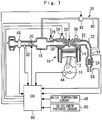
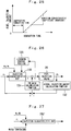
- a combustion chamber 14 is formed by a piston 12, and the piston 12 is connected to a crank shaft 16.
- the engine 10 is provided with an intake passage 18 for taking in an intake air into each of the cylinders, and in the intake passage 18, an electronically controlled throttle valve 20 for adjusting an intake air amount is provided.
- the engine 10 is provided with an exhaust passage 22 for exhausting an exhaust gas of each of the cylinders, and in the exhaust passage 22, a catalyst 24 such as a three-way catalyst or the like for purifying the exhaust gas is provided.
- the engine 10 is provided with an EGR mechanism 38 for refluxing a part of the exhaust gas to an intake system.
- the EGR mechanism 38 is provided with an EGR passage 40 connected between the intake passage 18 and the exhaust passage 22 and an EGR valve 42 for adjusting a flow rate of the exhaust gas flowing through the EGR passage 40.
- the system of this embodiment is provided with a sensor system including various sensors required for operations of the engine and a vehicle and an ECU (Engine Control Unit) 60 for controlling an operation state of the engine.
- a crank angle sensor 44 outputs a signal synchronized with rotation of the crank shaft 16, and an airflow sensor 46 detects an intake air amount.
- a water temperature sensor 48 detects a water temperature of an engine coolant
- an in-cylinder pressure sensor 50 detects an in-cylinder pressure
- an intake temperature sensor 52 detects a temperature of the intake air (outside air temperature).
- An air-fuel ratio sensor 54 detects the exhaust air-fuel ratio as a continuous detection value and is arranged on an upstream side of the catalyst 24.
- An oxygen concentration sensor 56 detects which of the rich and lean the exhaust air-fuel ratio is to a stoichiometric air-fuel ratio and is arranged on a downstream side of the catalyst 24.
- an engine rotation number and a crank angle are detected on the basis of an output of a crank angle sensor 44, and an intake air amount is detected by an airflow sensor 46.
- An engine load is calculated on the basis of the engine rotation number and the intake air amount, and a fuel injection amount is calculated on the basis of the intake air amount, the engine load, a water temperature and the like, and fuel injection timing and ignition timing are determined on the basis of the crank angle.
- learning control for learning control parameters on the basis of acquired values of the various control parameters is executed.
- to "acquire” includes meanings of detection, counting, measurement, calculation, estimation and the like.
- the weighting learning control described below is executed.
- the ECU 60 constitutes a learning device for executing the weighting learning control and is provided with a learning map having a plurality of grid points.
- specific contents of the weighting learning control will be explained, and specific examples of the control parameters will be explained in Embodiment 7 which will be described later and after.
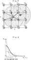
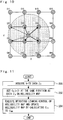
- FIG. 2 is an explanatory diagram schematically illustrating an example of the learning map used in the weighting learning control.
- This figure exemplifies a two-dimensional learning map from which one learning value is calculated on the basis of two reference parameters corresponding to the X-axis and the Y-axis.
- the learning map illustrated in Figure 2 has 16 grid points whose coordinates i and j change within a range of 1 to 4. At each grid point (i, j) on the learning map, a learning value Z ij of the control parameter is stored, respectively, capable of being updated.
- variable values z k , w kij , W ij (k), V ij (k), Z ij (k) attached with suffixes k indicate the k-th value corresponding to the k-th acquiring timing (calculation timing), and variable values w ij , W ij , V ij , Z ij without suffixes k indicate general values not discriminated by the acquiring timing.
- Figure 2 exemplifies a state in which the first and second acquired values z 1 , z 2 of the control parameter are reflected in a learning value Z ij of all the grid points by arrows, and in order to make the figure easy to be understood, a part of the arrows are omitted, and an update range of the learning values are indicated by a circle.
- W ij (k) indicates a weight integrated value acquired by totaling the first to the k-th weights w kij
- V ij (k) indicates a parameter integrated value acquired by totaling a multiplied value (z k * w kij ) of the k-th parameter acquired values z k and the weight w kij for the first to k-th sessions.
- the weighting learning control is to update the learning values Z ij (k) at the individual grid points so that the larger the weight w kij is, the more the parameter acquired values z k is reflected in the learning value Zij(k).
- the learning map can be updated by calculating the k-th learning value Z ij (k) at all the grid points (i, j) on the basis of the k-th parameter acquired value z k and the weight Wkij.
- the weight w kij at each grid point (i, j) corresponding to the k-th parameter acquired value z k is calculated from Gaussian function indicated in an equation in the following Formula 6 so as to satisfy 1 ⁇ w kij ⁇ 0.
- the Gaussian function constitute the weight setting means of this embodiment, and the larger a distance from a position of the parameter acquired value z k (reference position) on the learning map to the grid point (i, j), the more the weight w kij at the grid point (i, j) is decreased.
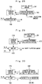
- FIG. 3 is a characteristic diagram illustrating a decrease characteristic of the weight by the Gaussian function in Embodiments 1 of the present invention.
- the decrease characteristic of the weight means a relationship between the weight decreasing in accordance with the distance from the reference position and the distance.
- the weight w kij acquired by the Gaussian function becomes larger if the grid point is closer to the reference position and decreases in a state of a normal distribution curve if the grid point is farther from the reference position. Therefore, a degree at which the parameter acquired value z k is reflected in the learning value Z ij (learning effect) is larger if the grid point is closer to the reference position and decreases if the grid point becomes farther from the reference position.
- the reference character ⁇ indicated in the above-described Formula 6 is a standard deviation that can be set to an arbitrary value, and the decrease characteristic of the Gaussian function changes in accordance with the standard deviation ⁇ . That is, the weight w kij has, as indicated by a dotted line in Figure 3 , a larger peak value present in the vicinity of the reference position if the standard deviation ⁇ is smaller but it rapidly decreases as getting farther from the reference position. As a result, if the standard deviation ⁇ is smaller, steep learning is executed only in the vicinity of the reference position, and though responsiveness of learning becomes high, irregularity can easily occur on a curved surface of the learning map.
- the weight w kij has a smaller peak value if the standard deviation ⁇ is larger and gently decreases as getting farther from the reference position as indicated by a one-dot chain line in Figure 3 .
- the learning map can be made a smooth curved surface.
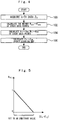
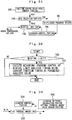
- Figure 4 is a flowchart of the control executed by an ECU in Embodiment 1 of the present invention.
- a routine illustrated in this figure is assumed to be repeatedly executed during an operation of an engine.
- the routine illustrated in Figure 4 first, at Step 100, the k-th data (parameter acquired value) z k is acquired.
- z k_1 indicates a first-axis coordinate of the parameter acquired value Z K (the X-axis coordinate in Figure 2 , for example), and z k-2 indicates a second-axis coordinate of the parameter acquired value Z K (the Y-axis coordinate).
- Z ij_1 indicates a first-axis coordinate i of the grid point (i, j) corresponding to the learning value Z ij
- Z ij_2 indicates a second-axis coordinate j of the same grid point (i, j).
- ⁇ 1, ⁇ 2 in the same equation correspond to the first-axis coordinate component and the second-axis coordinate component of the above-described standard deviation ⁇ .
- w kijlm 1 2 ⁇ ⁇ 1 exp ⁇ z k_ 1 ⁇ Z ijklm ... _ 1 2 ⁇ 1 2 ⁇ 1 2 ⁇ ⁇ 2 exp ⁇ z k_ 2 ⁇ Z ijklm ⁇ _ 2 2 ⁇ 2 2 ⁇ 1 2 ⁇ ⁇ 3 exp ⁇ z k_ 3 ⁇ Z ijklm ⁇ _ 3 2 ⁇ 3 2 ⁇ ⁇ ⁇
- the value of the learning value Z ij to be stored as an initial value by theoretical calculation in design or the like can be stored in advance as initial values of the integrated values W ij and V ij . Then, in the first session of the learning operation, the initial value of the learning value Z ij can be set to a desired value by the equations in the above-described Formula 4 and Formula 5. Moreover, by setting the weight integrated value W ij large at the grid point (i, j) where learning is to be expedited and by setting the weight integrated value W ij small at the grid point (i, j) where learning is to be delayed, an initial condition of the learning speed can be also adjusted easily.
- Embodiment 2 of the present invention will be explained.
- This embodiment is characterized in that in the configuration similar to the above-described Embodiment 1, a primary function is used as the weight setting means.
- the same constituent elements are given the same reference numerals as those in Embodiment 1, and the explanation will be omitted.
- Embodiment 3 of the present invention will be explained.
- This embodiment is characterized in that in the configuration similar to the above-described Embodiment 1, a trigonometric function is used as the weight setting means.
- the same constituent elements are given the same reference numerals as those in Embodiment 1, and the explanation will be omitted.
- a request might be different for each region on the learning map.
- the learning map there are a region where a change in the control parameter is large and a region where the change in the control parameter is small (little change) in many cases.
- the weight in the method of setting the weight in accordance only with the distance between the position of the parameter acquired value z k and the grid point, it is difficult to set the weight so that the learning speed or efficiency at each grid point become appropriate. That is, in this method, even between the grid points in different regions, learning at the same level is made if the distances are equal, and there is a problem that accurate learning control cannot be made. Moreover, it is difficult to find a certain weight conforming to the entire learning map.
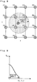
- Figure 7 is an explanatory diagram schematically illustrating an example of the learning map used for the weighting learning control in Embodiment 4 of the present invention.
- the learning map is divided into a plurality of regions.
- Figure 7 exemplifies an instance in which the part of the learning map is divided into two regions A and B.
- the region A is a region where a change of the control parameter during an operation of the engine and the like, for example, is large
- the region B is a region where a change of the control parameter is small.
- the decrease characteristic of the weight w kij Gaussian function
- the decrease characteristic of the weight w kij is configured to be switched for each of the regions A and B.
- the region A in which steep learning is needed for example, setting is made such that a rapid change of the weight w kij can be made, responsiveness or control efficiency of the learning can be improved, and an operation such as failsafe and the like can be made stable.
- the region B in which gentle learning can be allowed by making setting such that the weight w kij is gently changed in a relatively wide grid point range, the calculation load in learning can be suppressed, and the learning map can be made smooth. Therefore, the weighting conforming to the entire learning map can be easily realized.
- the number of regions to be provided on the learning map may be set to an arbitrary number.
- the decrease characteristic of the weight w kij does not have to be made different among all the regions, and it is only necessary to make the decrease characteristic different between at least two regions.
- the weight w kij is set on the basis of the decrease characteristic of the region to which the grid point belongs in the individual grid points (i, j).
- the present invention is not limited to this and may be so configured as in a variation described below.
- the weight is set for all the grid points.
- the weight w lij for all the grid points including the regions A and B is set on the basis of the decrease characteristic of the region A (Gaussian function of the standard deviation ⁇ A ).
- the weight w lij for all the grid points including the regions A and B is set on the basis of the decrease characteristic of the region B (Gaussian function of the standard deviation ⁇ B ).
- the responsiveness, speed, efficiency and the like of the learning at all the grid points can be switched in accordance with the characteristic of the region to which the parameter acquired value z k belongs. That is, if the parameter acquired value z k belongs to the region A requiring steep learning, the weight w kij can be set for all the grid points by the Gaussian function of the standard deviation ⁇ A . Furthermore, if the parameter acquired value z k belongs to the region B not requiring steep learning, the weight w kij can be set for all the grid points by the Gaussian function of the standard deviation ⁇ B . Therefore, the weighting conforming to the entire learning map can be easily realized.
- Embodiment 5 of the present invention will be explained.
- This embodiment is characterized in that update of the learning value at the grid point far from the reference position more than necessary is prohibited in the configuration similar to the above-described Embodiment 1.
- the same reference numerals are given to the same constituent elements as those in Embodiment 1, and the explanation will be omitted.
- Figure 9 is a characteristic diagram illustrating a characteristic of weighting according to Embodiment 5 of the present invention. As illustrated in this figure, at the grid point where the distance
- the weight w kij is gradually brought close to 0, and at the grid point where this distance is larger than a certain degree, even if the learning value is updated, the learning effect is small (learning does not become effective).
- the effective range R is set as a distance which includes all the grid points where learning becomes effective and can alleviate the calculation load of the learning processing.
- the equations in the above-described Formulas 1 to 5 are executed by excluding the grid points where the weight w kij is set to 0.
- the present invention is not limited to that, and it is only necessary that wasteful calculation at the grid point where the distance
- the learning values of all the grid points where learning is effective can be updated in one session of the learning operation.
- the standard deviation ⁇ of the Gaussian function is set large, and the learning map is to be made smooth, there is a concern that mis-learning that the learning value is updated meaninglessly can occur even in a region where the control parameter has not been actually acquired in the learning map.
- it is configured such that a reliability map for evaluating reliability of the learning map is used.
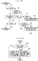
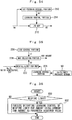
- FIG 10 is an explanatory diagram schematically illustrating an example of the reliability map in Embodiment 6 of the present invention.
- the reliability map has a plurality of the grid points configured similarly (same dimensional number) to the learning map, and at the individual grid points, reliability evaluation values C ij which are indexes indicating reliability of the learning values Z ij (k) are stored, respectively, capable of being updated.
- the reliability evaluation values C ij at all the grid points have their initial values set to 0 and they change within a range of 0 to 1.
- the reliability map is updated such that the higher the reliability of the learning value Z ij is, the larger the reliability evaluation value C ij at the corresponding grid points (i, j) becomes.
- a value less than 1 may be set to the reliability acquired value c k , and particularly if the reliability of the parameter acquired value z k is determined to be low, the reliability acquired value c k may be set to 0. That is, at Step 202, the reliability acquired value c k having a value corresponding to the reliability of the parameter acquired value z k is set to the reference position.
- the weighting learning control similar to the learning map is executed to the reliability map, and each time the control parameter is acquired, the reliability evaluation value C ij of each grid point is calculated, and the reliability map is updated.
- This weighting learning control is realized by equations in the following Formulas 9 to 14.
- the parameter acquired value z k (z l ) and the learning value Z ij (k) are replaced by the reliability acquired value c k (c l ) and the reliability evaluation value C ij in the above-described Formulas 1 to 6.
- the other variable values not replaced are attached with dashes '''''' indicating that they are different from those used in the learning map.
- the reliability acquired value c k according to its reliability was acquired at the same position as the parameter acquired value z k , for example, the weight (reliability weight) w kij ' is set at all the grid points where learning is effective, and the reliability evaluation value C ij is updated.
- the reliability evaluation values C ij at the individual grid points are updated so that the larger the reliability weight w kij ' is, the more the reliability acquired value c k is reflected.
- the reliability weight w kij ' is set by using the Gaussian function illustrated in the equation in the above-described Formula 14 so that the larger the distance from the reference position (position of the reliability acquired value c k )to the grid point is, the more the reliability weight w kij ' is decreased.
- the standard deviation ⁇ c of the Gaussian function determining the decrease characteristic of the reliability weight w kij ' is set to a value sufficiently smaller than the standard deviation ⁇ of the learning map ( ⁇ >> ⁇ c ). That is, the decrease characteristic when the reliability weight w kij ' is decreased in accordance with the distance from the reference position is set steeper than the decrease characteristic of the weight w kij of the learning map.
- the reliability weight w kij ' becomes larger only in the vicinity of the reference position where the control parameter was actually acquired and rapidly decreases as getting far from the reference position. Moreover, in a region where the reliability evaluation value C ij increased by learning is limited only to the vicinity of the reference position. Therefore, in a region where the control parameter is acquired at a high frequency, the reliability evaluation value C ij at each of the grid points becomes a large value. On the other hand, in a region where the control parameter is scarcely acquired, the reliability evaluation value C ij becomes a small value, and particularly in a region without an acquisition history of the control parameter, the reliability evaluation value C ij becomes a value close to 0. That is, in a value of the reliability evaluation value C ij , reliability of the learning value Z ij on whether or not the current learning value Z ij is calculated on the basis of the actually acquired control parameter is reflected.
- the reliability evaluation value C ij at each grid point of the reliability map the reliability of the learning value Z ij at the same grid point can be reflected.
- the reliability acquired value C k can be reflected in the reliability evaluation value C ij at each grid point. Therefore, the reliability of the learning value at each grid point can be efficiently calculated in one session of the learning operation.
- the reliability of the learning value Z ij is evaluated on the basis of the reliability evaluation value C ij at the corresponding grid point (i, j) on the reliability map, and appropriate corresponding control can be executed on the basis of the evaluation result.
- the reliability evaluation value C ij is at a predetermined determination value or more, the learning value Z ij is determined to be reliable, and the learning value Z ij can be used as it is for control.
- the reliability evaluation value C ij is less than the above-described determination value, it is determined that the learning value Z ij is not reliable, and a conservative safe value is used instead of the learning value Z ij , or the learning value Z ij can be corrected to a safe side (if it is at an ignition timing, for example, correction is made to a delay angle side, for example).
- the reliability evaluation value C ij is reflected in the learning value Z ij by means such as addition, multiplication and the like, for example, so that the learning value Z ij can be continuously increased/decreased in accordance with the reliability.
- Figure 10 illustrates a specific example of the reliability map
- the equation in the above-described Formula 14 illustrates a specific example of the reliability map weight setting means
- the routine illustrated in Figure 11 illustrates a specific example of the reliability map learning means.
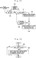
- FIG 12 is a control block diagram illustrating ignition timing control according to Embodiment 7 of the present invention.
- a system of this embodiment is provided with an MBT map 100 included in a storage circuit or a calculation function of the ECU 60, a combustion gravity center calculation portion 102, a combustion gravity center target setting portion 104, an FB gain calculation portion 106, and a learning control portion 108.
- the MBT map 100 is constituted by a multi-dimensional learning map for calculating ignition timing which is a control parameter on the basis of a plurality of reference parameters.
- an engine rotation number Ne an engine load KL, a water temperature, a valve timing control amount by the variable valve mechanisms 34 and 36 such as a VVT and the like, a control amount of the EGR valve 42 and the like can be cited.
- the learning value Z ij (k) of the MBT Minimum spark advance for Best Torque which is an ignition timing when an engine torque is maximized is stored, respectively.
- MBT control for matching the ignition timing with the MBT is executed.
- ignition timing Adv which is a feed-forward (FF) term is calculated.
- the combustion gravity center calculation portion 102 calculates a combustion gravity center CA 50 acquired from combustion at this ignition timing Adv by an equation in the following Formula 15 on the basis of an output of the in-cylinder pressure sensor 50 and the like.
- reference character P denotes an in-cylinder pressure
- reference character V denotes an in-cylinder volume
- reference character ⁇ denotes a specific heat ratio
- reference character ⁇ s denotes a combustion start crank angle
- reference character ⁇ e denotes a combustion end crank angle
- Embodiment 8 of the present invention will be explained by referring to Figure 14 .
- This embodiment is characterized in that, by using the reliability map described in the above-described Embodiment 6, an update amount of the learning value of the MBT in a transition operation of the engine is suppressed as compared with that in a steady operation.
- the same reference numerals are given to the same constituent elements as those in Embodiments 6 and 7, and the explanation will be omitted.
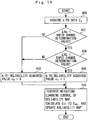
- FIG 14 is a flowchart of the control executed by the ECU in Embodiment 8 of the present invention. This figure describes only the processing relating to the learning of the reliability map.
- Step 400 the ignition timing Adv' after correction which is the k-th data (parameter acquired value) z k is acquired. Subsequently, at Step 402, it is determined whether or not a change amount ⁇ Ne per unit time of an engine rotation number is less than a predetermined rotation number rapid change determination value, and at Step 404, it is determined whether or not a change amount ⁇ KL per unit time of an engine load is less than a predetermined load rapid change determination value.
- These determination values are set on the basis of minimum values of the change amounts ⁇ Ne and ⁇ KL at which an error occurs in calculated value of the ignition timing or the combustion gravity center, for example.
- the reliability evaluation value C ij (k) updated by the above-described processing is reflected in the learning value Z ij (k) of the ignition timing by equations in the following Formula 16 and Formula 17, for example. These equations are used instead of the equations in Formula 1 and Formula 2 explained in the above-described Embodiment 1.
- W ij k W ij k ⁇ 1 + w kij * C ij k
- V ij k V ij k ⁇ 1 + z k * w kij * C ij k
- the following effects can be obtained.
- the more stable the operation state is when the control parameter is acquired that is, the higher the reliability of the parameter acquired value (ignition timing Adv') is, the apparent weight (w kij * C ij (k)) at each grid point can be increased, and the update amount of the learning value Z ij (k) can be made larger.
- the above-described apparent weight is decreased so as to make the update amount of the learning value Z ij (k) smaller, and the learning can be stopped or suppressed. As a result, learning in the steady operation can be promoted, and mis-learning in the transition operation can be suppressed.
- the equation in the above-described Formula 20 has a characteristic substantially similar to the Gaussian function, and the reliability coefficient ⁇ is set so as to decrease as the ⁇ CA 50 becomes larger (the farther the combustion gravity center CA 50 is deviated from the combustion gravity center target value). Moreover, a decrease characteristic of the reliability coefficient ⁇ is adjusted in accordance with a size of an adjustment term ⁇ CA50 . Moreover, the equations in the above-described Formula 21 and Formula 22 are used instead of the equations in Formula 1 and Formula 2 explained in Embodiment 1.
- the lower the estimation accuracy of the MBT is, the smaller the reliability coefficient ⁇ can be set, and a degree of reflection of the estimated value of the MBT in the learning value Z ij (k) can be lowered. Therefore, by estimating the MBT, the learning chances are increased, while the update amount of the learning value Z ij (k) can be appropriately adjusted in accordance with the estimation accuracy, and mis-learning can be suppressed.
- the reliability map is used instead of the reliability coefficient ⁇ .
- Embodiment 9 it is configured such that the MBT is learned by the MBT map 110.
- the TK region is a region where trace knock (weak knock occurring before occurrence of a full-fledged knock) before advancing the ignition timing to the MBT, and in this region, learning of the MBT becomes difficult.
- the ignition timing is learned by a TK map 124 which will be described later in the TK region.
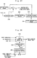
- FIG 19 is a control block diagram illustrating ignition timing control according to Embodiment 10 of the present invention.
- a system of this embodiment is provided with an MBT map 120 configured similarly to the above-described Embodiment 9, a learning control portion 122, the TK map 124, and a Min selection portion 126.
- the TK map 124 is a multi-dimensional learning map configured similarly to the MBT map 120, the at each grid point of the TK map 124, the learning value Z ij (k) of TK ignition timing which is a control parameter is stored capable of being updated, respectively.
- the TK ignition timing is defined as ignition timing at which the trace knock occurs in the TK region before the ignition timing reaches the MBT (before the MBT is realized), that is, the ignition timing on the most advanced angle side capable of being realized without causing a full-fledged knock.
- the learning value Z ij (k) of the MBT map 120 is noted as an MBT learning value Z1
- the learning value Z ij (k) of the TK map 124 is noted as a TK learning value Z2.
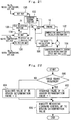
- FIG. 20 is a flowchart of the control executed by the ECU in Embodiment 10 of the present invention.
- the routine illustrated in this figure describes only the learning processing of the TK ignition timing.
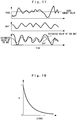
- the routine illustrated in Figure 20 first, at Step 500, it is determined whether or not the trace knock occurred on the basis of an output waveform of the in-cylinder pressure sensor 50. If this determination holds true, at Step 502, the current ignition timing (TK ignition timing) is acquired as the parameter acquired value z k . Then, the weighting learning control is executed on the basis of this acquired value, and the TK learning value Z2 is updated.
- the ignition timing at this point of time is acquired and learned as the TK ignition timing. Moreover, if the ignition timing reaches the MBT, the MBT is acquired and learned. As a result, in the learning control of this embodiment, each time ignition is performed, either one of the MBT map 120 and the TK map 124 is learned (updated).
- the learning values Z1 and Z2 are calculated from the MBT map 120 and the TK map 124, and a size relationship between the learning values Z1 and Z2 is determined by the Min selection portion 126.
- the Min selection portion 126 selects the smaller ignition timing (ignition timing on the more delayed angle side) in the MBT learning value Z1 and the TK learning value Z2 and outputs the selected ignition timing as the ignition timing Adv before correction.
- the processing after the ignition timing Adv is outputted is similar to the processing described in Embodiments 9.
- the following effects can be obtained. Since either one of the MBT and the TK ignition timing can be learned in learning of the ignition timing, the learning chances can be increased, and the ignition timing can be efficiently learned other than the MBT region. Moreover, in this embodiment, the ignition timing on the advanced angle side in the MBT learning value Z1 and the TK learning value Z2 can be selected. Therefore, while occurrence of the knock is avoided, the ignition timing is controlled to the advanced angle side as much as possible so that the operation performances and operation efficiency can be improved.
- the learning control portion 122 indicates specific examples of the weight setting means and the weighting learning means of the two learning maps composed of the MBT map 120 and the TK map 124.
- the routine in Figure 20 indicates a specific example of the TK ignition timing learning means
- the Min selection portion 126 indicates a specific example of selecting means.
- Embodiment 11 of the present invention will be explained.
- This embodiment is characterized in that, in addition to the configuration of the above-described Embodiment 10, a TK region map for confirming the TK region is employed.
- the same reference numerals are given to the same constituent elements of those in Embodiments 7 and 10, and the explanation will be omitted.
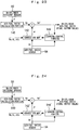
- FIG. 21 is a control block diagram illustrating ignition timing control according to Embodiment 11 of the present invention.
- a system of this embodiment is provided with an MBT map 130, a learning control portion 132, the TK map 134, a Min selection portion 136 configured similarly to the above-described Embodiment 10, and the TK region map 138.
- the TK region map 138 is a multi-dimensional learning map configured similarly to the MBT map 130 and the TK map 134, and at each grid point of the TK region map 138, a TK region determination value which is a control parameter is stored, respectively.
- the TK region determination value is the learning value Z ij (k) indicating whether or not the individual grid points of the TK map 134 belongs to a trace knock region, updated by the weighting learning control similar to the reliability map, and changes within a range of 0 to 1. Then, the larger a value of the TK region determination value is, the higher the possibility (reliability) that the grid point corresponding to the determination value belongs to the TK region.
- FIG. 22 is a flowchart illustrating the learning control of the TK region map 138 executed by the ECU in Embodiment 11 of the present invention.
- a routine illustrated in this figure is periodically executed in parallel with the learning processing of the MBT map 130, for example.
- the routine illustrated in Figure 22 first, at Step 600, it is determined whether or not the trace knock has occurred. If this determination holds true, it is the TK region, and the routine proceeds to Step 602, and an acquired value of the TK region determination value in the current operation region (position on the learning map determined by a combination of the reference parameters) is set to 1. On the other hand, if the determination at Step 600 does not hold true, it is not the TK region, and the routine proceeds to Step 604, and the acquired value of the TK region determination value is set to 0.
- the TK region determination values at all the grid points are updated.
- the TK region determination value corresponds to the control parameter and its learning value Z ij (k)I
- the acquired value of the TK region determination value corresponds to the parameter acquired value z k .
- the decrease characteristic of the weight w kij decreasing in accordance with the distance from the reference position is preferably set steep (the standard deviation ⁇ of the Gaussian function is set small). As a result, on the TK region map 138, the boundary of the TK region can be made clear.
- the weighting learning control of the TK ignition timing when executed, when the learning value is to be updated at each grid point of the TK map 134, the TK region determination value stored at the same position on the TK region map 138 is read out. Then, on the basis of the value of the read-out TK region determination value, it is determined whether or not the TK ignition timing is learned at the grid point (learning is effective or ineffective). As an example, it may be so configured that, if the TK region determination value is 0.5 or more, the learning value of the TK ignition timing is updated, and the learning value is not updated in the other cases.
- the ignition timing becomes 0. It is preferable that the TK map 134 is not used in a region where the TK region determination value is close to 0 (grid point) but the ignition timing is controlled on the basis only of the MBT map 130.
- the following effects can be obtained.
- the learning control portion 132 indicates specific examples of the weight setting means and the weighting learning means of the two learning maps, that is, the MBT map 130 and the TK map 134.
- the routine in Figure 22 indicates a specific example of TK region learning means.
- the TK region map 138 functions similarly to the reliability map with respect to the TK map 134
- Embodiment 11 corresponds to the configuration in which the reliability map is applied to the TK map 134.
- the reliability map reflecting a learning history of the MBT may be used at the same time with the MBT maps 100, 110, 120, and 130. In this case, the reliability evaluation value of the reliability map is updated together with the MBT map by the method described in the above-described Embodiment 6.
- the ignition timing is conservatively delayed a little.
- Embodiment 12 of the present invention will be explained.
- This embodiment is characterized in that the weighting learning control described in the above-described Embodiment 1 is applied to calculation control of an in-cylinder air-fuel ratio.
- the same reference numerals are given to the same constituent elements as those in Embodiment 1, and the explanation will be omitted.
- the in-cylinder air-fuel ratio is calculated on the basis of at least an output of the in-cylinder sensor 50, and this calculated value is corrected on the basis of an output of the air-fuel ratio sensor 54.
- This embodiment is to learn a correction map used for this correction by the weighting learning control.
- an exhaust air-fuel ratio detected by the air-fuel ratio sensor 54 has poor responsiveness. That is caused by the fact that a response delay of the sensor itself is large and moreover, a detection position is apart from a combustion chamber.
- the exhaust air-fuel ratio cannot be detected at time of a low temperature when the air-fuel ratio sensor is not activated, and detection according to a cylinder is also difficult.
- the in-cylinder air-fuel ratio an air-fuel ratio in combustion can be calculated every time and thus, responsiveness is good, and control with high accuracy can be realized.
- the in-cylinder air-fuel ratio basically has low calculation accuracy, it is preferably corrected on the basis of the output of the air-fuel ratio sensor 54.
- Figure 23 is a control block diagram illustrating the calculation control of the in-cylinder air-fuel ratio according to Embodiment 12 of the present invention.
- a system of this embodiment is provided with an air-fuel ratio calculation portion 140, a correction map 142, and a learning control portion 144.
- the air-fuel ratio calculation portion 140 calculates an in-cylinder air-fuel ratio (CPS detection air-fuel ratio) Ap by an equations in the following Formulas 23 to 25 on the basis of an in-cylinder pressure P detected by an in-cylinder pressure sensor (CPS) 50 and the like.
- CPS detection air-fuel ratio an in-cylinder air-fuel ratio
- the in-cylinder air mass is calculated by using an output of an airflow sensor 46 or on the basis of a principle that an in-cylinder pressure change in a compression stroke (a pressure difference between a start point and an end point of the compression stroke) ⁇ P is in proportion to the in-cylinder air mass.
- the lower heating value is defined as a heating value per unit mass of a fuel and is a known value determined in accordance with a component of the fuel and the like.
- the CPS detection heating value Q is a heating value in the cylinder calculated on the basis of an output of the in-cylinder pressure sensor 50 and the like, and each parameter used for the calculation is those explained in the above-described Formula 15.
- the in-cylinder air-fuel ratio Ap can easily fluctuate in accordance with the engine operation state.
- the in-cylinder air-fuel ratio Ap is corrected by an equation in the following Formula 26 on the basis of a multiplication type correction coefficient ⁇ reflecting the operation state, for example.
- reference character Ap denotes an in-cylinder air-fuel ratio before correction
- reference character Ap' denotes an in-cylinder air-fuel ratio after correction (final output value of the in-cylinder air-fuel ratio).
- the correction coefficient ⁇ is calculated by the correction map 142.
- Ap ′ Ap * ⁇
- the correction map 142 is a multi-dimensional learning map for calculating the correction coefficient ⁇ on the basis of a plurality of reference parameters including at least the engine rotation number Ne and the engine load KL, and at each grid point of the correction map 142, the learning value Z ij (k) of the correction coefficient ⁇ which is a control parameter is stored, respectively.
- the learning control portion 144 executes weighting learning control of the correction coefficient ⁇ . Specifically, first, on the basis of an equation in the following Formula 27, a ratio between an exhaust air-fuel ratio As detected by the air-fuel ratio sensor 54 and the in-cylinder air-fuel ratio Ap' after correction is calculated as the correction coefficient ⁇ . Then, the calculated value of the correction coefficient ⁇ is made the parameter acquired value z k , and the learning value Z ij (k) of the correction coefficient ⁇ at each grid point is updated.
- ⁇ As / Ap ′
- an average value of the in-cylinder air-fuel ratio Ap' of each cylinder may be employed as the in-cylinder air-fuel ratio Ap' in the equation in the above-described Formula 27.
- the air-fuel ratio sensor 54 has large response delay, the above-described learning control is to be executed only in the steady operation of the engine and is preferably prohibited in the transition operation.
- a configuration of a variation illustrated in Figure 24 may be employed.
- the in-cylinder air-fuel ratio Ap is corrected by an equation in the following Formula 28.
- the learning value Z ij (k) of the correction coefficient ⁇ is stored, respectively, and a learning control portion 144' uses a calculated value of the correction coefficient ⁇ calculated by an equation in the following Formula 29 as the parameter acquired value z k and executes the weighting learning control of the correction coefficient ⁇ .
- the effect described in the above-described Embodiment 1 can be obtained.
- the in-cylinder air-fuel ratio calculated by the in-cylinder pressure sensor 50 has a large error caused by a change in the operation state, even if a correction coefficient obtained by the prior-art learning method is used, improvement of practicability is difficult.
- the correction coefficients ⁇ and ⁇ can be quickly learned at all the grid points of the correction maps 142 and 142'.
- the air-fuel ratio calculation portion 140 indicates a specific example of in-cylinder air-fuel ratio calculating means
- the learning control portion 144 indicates specific examples of the weight setting means and the weighting learning means.
- Embodiment 13 of the present invention will be explained.
- This embodiment is characterized in that the weighting learning control described in the above-described Embodiment 1 is applied to learning control of a fuel injection characteristic.
- the same reference numerals are given to the same constituent elements as those in Embodiment 1, and the explanation will be omitted.
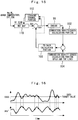
- Figure 25 is a characteristic diagram illustrating an injection characteristic of a fuel injection valve in Embodiment 13 of the present invention.
- a fuel injection amount of the fuel injection valve 26 has a characteristic of increasing in proportion to effective conduction time obtained by subtracting ineffective conduction time from conduction time and is controlled on the basis of conduction time t by an equation in the following Formula 30.
- a target injection amount Ft is a target value set by fuel injection control
- an injection characteristic coefficient corresponds to inclination of a characteristic line illustrated in Figure 25 .
- Conduction time t target injection amount Ft / injection characteristic coefficient + ineffective conduction time
- FIG. 26 is a control block diagram illustrating the learning control of the fuel injection characteristic executed in Embodiment 13 of the present invention. As illustrated in this figure, a system of this embodiment is provided with an injection characteristic map 150, an actual injection amount calculation portion 152, an FB gain calculation portion 154, and a learning control portion 156.
- the injection characteristic map 150 is a multi-dimensional learning map for calculating the conduction time t on the basis of reference parameters composed of the target fuel injection amount Ft, the engine rotation number Ne, and the engine load KL, for example, and at each grid point of the injection characteristic map 150, the learning value Z ij (k) of the conduction time t which is a control parameter is stored, respectively.
- the actual injection amount calculation portion 152 calculates the actual fuel injection amount (actual injection amount) Fr on the basis of the output of the in-cylinder pressure sensor 50, and the actual injection amount Fr is acquired by dividing the in-cylinder fuel mass described in the above-described Embodiment 12 by the correction coefficient ⁇ as illustrated in an equation in the following Formula 31.
- Actual injection amount Fr In ⁇ cylinder fuel mass / ⁇
- the FB gain calculation portion 154 compares the target fuel injection amount Ft with the actual injection amount Fr and calculates a correction amount of the conduction time t and corrects the conduction time t on the basis of the correction amount. Specifically, on the basis of the target fuel injection amount Ft, if the actual injection amount Fr is larger, the conduction time t is decreased, while if the actual injection amount Fr is smaller, the conduction time t is increased. As a result, conduction time t' after correction is calculated, and the fuel injection valve 26 is conducted in accordance with the conduction time t'.
- the learning control portion 156 uses the conduction time t' after correction as the parameter acquired value z k , executes the weighting learning control of the conduction time t and updates the learning value Z ij (k) stored at each grid point of the injection characteristic map 150. Since the fuel injection characteristic is a primary function as illustrated in Figure 25 , it is only necessary that there are two grid points on the injection characteristic map 150.
- the actual injection amount Fr is calculated on the basis of the output of the in-cylinder pressure sensor 50, and learning can be executed on the basis of this actual injection amount Fr and thus, even if the actual fuel injection amount cannot be detected, the learning control can be easily executed by using an existing sensor.
- the actual injection amount calculation portion 152 indicates a specific example of actual injection amount calculating means
- the learning control portion 156 indicates a specific example of the weight setting means and the weighting learning means.
- an injection characteristic map 150' is configured to calculate the conduction time t on the basis of the reference parameters composed of the target fuel injection amount Ft, the engine rotation number Ne, the engine load KL, and the water temperature. As a result, a difference in a warming-up state of the engine can be handled.
- Embodiment 14 of the present invention will be explained.
- This embodiment is characterized in that the weighting learning control described in the above-described Embodiment 1 is applied to an output correction coefficient of an airflow sensor.
- the same reference numerals are given to the same constituent elements as those in Embodiment 1, and the explanation will be omitted.
- a final detection air amount Sout is calculated by correcting a sensor output value S by an equation in the following Formula 32.
- reference character KFLC denotes a correction coefficient for output correction and is stored in a correction map 160 illustrated in Figure 28.
- the correction map 160 is a multi-dimensional learning map for calculating the correction coefficient KFLC on the basis of reference parameters composed of the engine rotation number Ne and an outside air temperature TA, for example, and at each grid point of the correction map 160, the learning value Z ij (k) of the correction coefficient KFLC which is a control parameter is stored, respectively.
- a system of this embodiment is provided with a learning reference calculation portion 162 and a learning control portion 164 in addition to the correction map 160.
- the learning reference calculation portion 162 calculates a learning reference value KFLC' of the correction coefficient by equations in the following Formula 33 and Formula 34 on the basis of an output of the air-fuel ratio sensor 54 and the fuel injection amount.
- the actual fuel injection amount Fr (equation in Formula 31) calculated in the above-described Embodiment 13 is preferably used as the fuel injection amount.
- KFLC ′ Air ⁇ fuel ratio detection air amount / sensor output value
- S Air ⁇ fuel ratio detection amount Air ⁇ fuel ratio sensor output * fuel injection amount
- the learning control portion 164 uses the learning reference value KFLC' of the correction coefficient calculated by the equation in the above-described Formula 33 as the parameter acquired value z k , executes the weighting learning control of the correction coefficient KFLC and updates the learning value Z ij (k) stored at each grid point of the correction map 160. Since the air-fuel ratio sensor 54 has a large response delay, the above-described learning control is to be executed only in the steady operation of the engine and is preferably prohibited in the transition operation.
- the learning reference calculation portion 162 indicates a specific example of the learning reference calculating means
- the learning control portion 164 indicates specific examples of the weight setting means and the weighting learning means.
- Embodiment 15 of the present invention will be explained.
- This embodiment is characterized in that the weighting learning control described in the above-described Embodiment 1 is applied to calculation control of a wall-surface fuel adhesion amount.
- the same constituent elements are given the same reference numerals as those in Embodiment 1, and the explanation will be omitted.
- the wall-surface fuel adhesion amount qmw which is an amount of an injected fuel adhering to a wall surface of an intake port or the like is calculated, and the fuel injection amount is corrected on the basis of this calculation result.
- the wall-surface fuel adhesion amount qmw is acquired from a wall-surface fuel adhesion amount calculation map (QMW map).
- the weighting learning control is applied to this QMW map.
- FIG. 29 is a control block diagram illustrating the learning control of the wall-surface fuel adhesion amount in Embodiment 15 of the present invention.
- a system of this embodiment is provided with a QMW map 170, a learning reference calculation portion 172, and a learning control portion 174.
- the QMW map 170 is a multi-dimensional learning map for calculating the wall-surface fuel adhesion amount qmw on the basis of reference parameters including the engine rotation number Ne, the engine load KL, and a valve timing control amount by VVT and the like, for example, and at each grid point of the QMW map 170, the learning value Z ij (k) of the wall-surface fuel adhesion amount qmw which is a control parameter is stored, respectively.
- the wall-surface fuel adhesion amount qmw calculated by the QMW map 170 is reflected in a target injection amount of the fuel in the fuel injection control.
- the learning reference calculation portion 172 calculates a learning reference value qmw' of the wall-surface fuel adhesion amount by an equation in the following Formula 35 on the basis of the wall-surface fuel adhesion amount qmw calculated by the QMW map 170, an output of the air-fuel ratio sensor 54, and parameters for determining acceleration and deceleration of the engine.
- the parameters for determining acceleration/deceleration an output of a throttle sensor, an engine rotation number and the like, for example, can be cited.
- qmw ′ qmw + adjustment amount ⁇
- the learning reference value qmw' of the wall-surface fuel adhesion amount cannot be directly detected or calculated easily and thus, it is acquired by adding an adjustment amount ⁇ to the calculated value qmw by the QMW map 170.
- the adjustment amount ⁇ is set as a micro amount for changing the wall-surface fuel adhesion amount qmw little by little, and as a specific example, it is determined by the following processing:
- the learning control portion 174 uses the learning reference value qmw' of the wall-surface fuel adhesion amount calculated by the equation in the above-described Formula 35 as the parameter acquired value z k , executes the weighting learning control of the wall-surface fuel adhesion amount qmw and updates the learning value Z ij (k) stored at each grid point of the QMW map 170.
- the learning reference calculation portion 172 indicates a specific example of the learning reference calculating means
- the learning control portion 174 indicates specific examples of the weight setting means and the weighting learning means.
- Embodiment 16 of the present invention will be explained.
- This embodiment is characterized in that the weighting learning control described in the above-described Embodiment 1 is applied to learning control of valve timing.
- the same reference numerals are given the same constituent element as those in Embodiment 1, and the explanation will be omitted.
- FIG. 30 is a control block diagram illustrating learning control of the valve timing in Embodiment 16 of the present invention.
- a system of this embodiment is provided with a VT map 180, a learning reference calculation portion (optimal VT search portion) 182, and a learning control portion 184.
- the VT map 180 is a multi-dimensional learning map for calculating the valve timing VT on the basis of reference parameters composed of the engine rotation number Ne and the engine load KL, for example, and at each grid point of the VT map 180, the learning value Z ij (k) of the valve timing VT which is a control parameter is stored, respectively.
- valve timing VT is calculated by the VT map 180 on the basis of each of the above-described reference parameters, and this calculated value is outputted to an actuator of the variable valve mechanism 34 (36).
- a control target of this embodiment is preferably the intake valve 30 but may be the exhaust valve 32.
- the optimal VT search portion 182 searches the optimal valve timing at which fuel consumption becomes optimal, for example, and the search result is outputted as a learning reference value VT' of the valve timing.
- a searching method of the optimal valve timing a general method is used.
- a fuel consumption rate per unit time is calculated on the basis of information such as the in-cylinder fuel mass calculated on the basis of the output of the in-cylinder pressure sensor 50 as described above, for example, the engine rotation number and the like, and by changing the valve timing VT little by little while this calculated value is monitored, the optimal valve timing VT can be found.
- the learning control portion 184 uses the learning reference value VT' of the valve timing as the parameter acquired value z k , executes the weighting learning control of the valve timing VT and updates the learning value Z ij (k) stored at each grid point of the VT map 180.
- the optimal VT search portion 182 indicates a specific example of the learning reference calculating means
- the learning control portion 184 indicates specific examples of the weight setting means and the weighting learning means.
- the weight w kij used by the weighting learning control may be configured to be made smaller than that after completion of the search processing.
- the weight w kij instead of making the weight w kij small, it may be so configured that the above-described reliability map is used at the same time.
- the learning control is to be executed during the search processing of the valve timing, it is only necessary that the reliability acquired value is set to a small value at the reference position on the reliability map (position of the learning reference value VT').
- the update amount of the learning value can be adjusted as appropriate in accordance with reliability on whether or not the valve timing is optimized, and learning accuracy can be improved.
- Embodiment 17 of the present invention will be explained.
- This embodiment is characterized in that the weighting learning control described in the above-described Embodiment 1 is applied to learning control of misfire limit ignition timing.
- the same reference numerals are given to the same constituent elements as those in Embodiment 1, and the explanation will be omitted.
- FIG 31 is a control block diagram illustrating ignition timing control according to Embodiment 17 of the present invention.
- a system of this embodiment is provided with ignition timing delay-angle control portion 190, a misfire limit map 192, a Max selection portion 194, and a learning control portion 196.
- the ignition timing delay-angle control portion 190 executes general controls for delaying the ignition timing such as knock control, speed-change response control, catalyst warming-up control and the like, for example, and outputs a target ignition timing Adv1 set by delaying through these controls.
- the misfire limit map 192 is a multi-dimensional learning map for calculating misfire limit ignition timing Adv2 on the basis of a plurality of reference parameters, and at each grid point of the misfire limit map 192, the learning value Z ij (k) of the misfire limit ignition timing Adv2 which is a control parameter is stored, respectively.
- the misfire limit ignition timing is defined as ignition timing on the most delayed angle side that can be realized without occurrence of a misfire by ignition timing delay-angle control.
- the engine rotation number Ne, the engine load KL, the water temperature, a control amount of the valve timing, a control amount of EGR and the like, for example can be cited.
- the Max selection portions 194 selects the larger ignition timing (ignition timing on the more delayed angle side) in the target ignition timing Adv1 delayed by the ignition timing delay-angle control and the misfire limit ignition timing Adv2 calculated by the misfire limit map 192 and outputs the selected ignition timing.
- the learning control portion 196 executes the weighting learning control of the misfire limit ignition timing Adv2 by the processing illustrated in Figure 32.
- Figure 32 is a flowchart of control executed by the ECU in Embodiment 17 of the present invention.
- Step 700 it is determined whether or not the current ignition timing is a misfire limit.
- the above-described CPS detection heating value Q is calculated on the basis of the output of the in-cylinder pressure sensor 50, and if this calculated amount becomes a predetermined determination value or less corresponding to the lower limit value of normal combustion, occurrence of a misfire is detected.
- the number of misfire times per unit time is counted, and if the count value exceeds a predetermined determination value corresponding to the misfire limit, it is determined that the current ignition timing reaches the misfire limit ignition timing.
- Step 700 the routine proceeds to Step 702, and by using the current ignition timing as the parameter acquired value z k , the weighting learning control of the misfire limit ignition timing Adv2 is executed, and the learning value Z ij (k) stored at each grid point of the misfire limit map 192 is updated.
- the learning control of the misfire limit ignition timing the effect described in the above-described Embodiment 1 can be obtained, and the misfire limit can be efficiently learned.
- the ignition timing can be delayed to the maximum in accordance with a delay-angle request, and controllability of the ignition timing can be improved.
- the weighting learning control is executed only when the misfire limit is reached, but since the misfire limit ignition timing can be efficiently learned at all the grid points of the misfire limit map 192 in one session of the learning operation, even in a small number of learning chances, learning can be made sufficiently.
- Step 700 in Figure 32 indicates a specific example of misfire limit determining means
- Step 702 indicates a specific example of misfire limit learning means
- the Max selection portion 194 indicates a specific example of selecting means.
- the misfire region map has a configuration and a function similar to the TK region map 138 described in the above-described Embodiment 11 and at each grid point of the misfire region map, the learning value of a misfire region determination value is stored, respectively.
- misfire limit is detected, a detection position of the misfire limit is made a reference position, a misfire region determination value is set at the same position on the misfire region map, and moreover, it is only necessary that the weighting learning control of the misfire region map is executed. As a result, a boundary of the misfire limit region can be made clear.
- Embodiment 18 of the present invention will be explained.
- This embodiment is characterized in that the weighting learning control described in the above-described Embodiment 1 is applied to learning control of a fuel increase amount correction value.
- the same reference numerals are given to the same constituent elements as those in Embodiment 1, and the explanation will be omitted.
- FIG 33 is a control block diagram illustrating learning control of the fuel increase amount correcting value in Embodiment 18 of the present invention.
- a system of this embodiment is provided with a fuel increase amount map 200, a learning reference calculation portion (optimal increase amount value search portion) 202, and a learning control portion 204.
- the fuel increase amount map 200 is a multi-dimensional learning map for calculating a fuel increase amount value Fd on the basis of reference parameters composed of the engine rotation number Ne and the engine load KL, for example, and at each grid point of the fuel increase amount map 200, the learning value Z ij (k) of the fuel increase amount value Fd which is a control parameter is stored, respectively.
- the fuel increase amount value Fd is a correction amount (power increase amount value) for applying increase-amount correction to a target injection amount in accordance with an acceleration request or the like in the fuel injection control.
- the optimal increase amount value search portion 202 searches an optimal value of the fuel increase amount at which an engine torque is maximized on the basis of the output of the in-cylinder pressure sensor 50, for example, and outputs the search result as a learning reference value Fd' of the fuel increase amount value.
- the learning control portion 204 uses the learning reference value Fd' of the fuel increase amount value as the parameter acquired value z k , executes the weighting learning control of the fuel increase value Fd and updates the learning value Z ij (k) stored at each grid point of the fuel increase amount map 200.
- the learning control portion 204 indicates specific examples of the weight setting means and the weighting learning means.
- Embodiment 19 of the present invention will be explained.
- This embodiment is characterized in that the weighting learning control described in the above-described Embodiment 1 is applied to learning control of ISC (Idle Speed Control).
- ISC Intelligent Speed Control
- the same reference numerals are given to the same constituent elements as those in Embodiment 1, and the explanation will be omitted.
- idle operation control for applying feedback control of an opening degree of an intake passage (ISC opening degree) on the basis of the engine rotation number and the like in an idle operation and learning control for learning the ISC opening degree corrected by the idle operation control.
- the opening degree of the intake passage means an opening degree of an ISC valve or a throttle valve 20.
- Figure 34 is a control block diagram illustrating the learning control of the ISC in Embodiment 19 of the present invention.
- a system in this embodiment is provided with an ISC map 210, an ISC feedback control portion 212, and a learning control portion 214.
- the ISC map 210 is a learning map for calculating an ISC opening degree VO on the basis of the engine rotation number Ne, and at each grid point of the ISC map 210, the learning value Z ij (k) of the ISC opening degree VO which is a control parameter is stored, respectively.
- the ISC opening degree VO is calculated by the ISC map 210 on the basis of the engine rotation number Ne, and this calculated value is outputted to a driving portion of the ISC valve or the throttle valve 20.
- the ISC feedback control portion 212 corrects (feedback control) the ISC opening degree VO so that the engine rotation number Ne in the idle operation matches a target rotation number.
- the ISC opening degree VO' corrected by that is inputted into the learning control portion 214.
- the learning control portion 214 uses the ISC opening degree VO' after correction as the parameter acquired value z k , executes the weighting learning control of the ISC opening degree VO and updates the learning value Z ij (k) stored at each grid point of the ISC map 210.
- the learning control of the ISC opening degree in the learning control of the ISC opening degree, the effect described in the above-described Embodiment 1 can be obtained. Therefore, even in a small number of learning chances, the ISC opening degree can be efficiently learned, and stability in the idle operation can be improved.
- the learning control portion 214 indicates specific examples of the weight setting means and the weighting learning means. Moreover, in Embodiment 19, it may be so configured that, the larger the engine rotation number Ne is deviated from the target rotation number, it is determined that reliability of the learning value lowers, and the weight w kij is made smaller.
- This configuration is realized by multiplying the weight w kij by a coefficient which decreases larger as the difference between the engine rotation number Ne and the target rotation number becomes larger.
- the engine rotation number Ne is controlled to a value close to the target rotation number, and the higher the accuracy of the idle operation control, the update amount of the learning value can be increased at all the grid points.
- the engine rotation number Ne is deviated from the target rotation number and the accuracy of the idle operation control is low, the learning can be suppressed. Therefore, learning accuracy of the entire ISC map 210 can be improved.
- Embodiment 20 of the present invention will be explained.
- This embodiment is characterized in that the weighting learning control described in the above-described Embodiment 1 is applied to learning control of EGR.
- the same reference numerals are given to the same constituent elements as those in Embodiment 1, and the explanation will be omitted.
- FIG 35 is a control block diagram illustrating learning control of EGR according to Embodiment 20 of the present invention.
- a system of this embodiment is provided with an EGR control portion 220, a misfire limit EGR map 222, a Max selection portion 224, and a learning control portion 226.
- the EGR control portion 220 is to execute known EGR control and outputs a requested EGR amount E1 calculated by the EGR control.
- an "EGR amount” means an arbitrary control parameter corresponding to an amount of an EGR gas flowing into a cylinder and specifically it may be any of parameters of an opening degree of the EGR valve 42, the EGR gas amount flowing through the EGR passage 40, and an EGR rate which is a ratio of the EGR gas amount to the intake air amount.
- the misfire limit EGR map 222 is a multi-dimensional learning map for calculating a misfire limit EGR amount E2 on the basis of a plurality of reference parameters, and at each grid point of the misfire limit EGR map 222, the learning value Z ij (k) of the misfire limit EGR amount E2 which is a control parameter is stored, respectively.
- the misfire limit EGR amount is defined as the maximum EGR amount that can be realized by the EGR control without occurrence of a misfire.
- the engine rotation number Ne the engine load KL, the water temperature, the control amount of the valve timing and the like can be cited.
- the Max selection portion 224 selects the larger EGR amount in the requested EGR amount E1 calculated by the EGR control and the misfire limit EGR amount E2 calculated by the misfire limit EGR map 222 and outputs the selected EGR amount.
- the EGR control is executed on the basis of an output amount of this EGR amount.
- the learning control portion 226 executes the weighting learning control of the misfire limit EGR amount E2 by processing illustrated in Figure 36.
- Figure 36 is a flowchart of the control executed by the ECU in Embodiment 20 of the present invention. In a routine illustrated in this figure, first, at Step 800, it is determined whether or not the current ignition timing is a misfire limit. This determination processing is processing similar to the above-described Embodiment 17 ( Figure 32 ).
- Step 800 uses the current EGR amount as the parameter acquired value z k , executes the weighting learning control of the misfire limit EGR amount E2 and updates the learning value Z ij (k) stored at each grid point of the misfire limit EGR map 222.
- the learning control of the EGR uses the effect obtained in the above-described Embodiment 1 to be obtained, and the misfire limit EGR amount can be efficiently learned.
- the EGR amount can be ensured to the maximum in accordance with a request, and controllability of the EGR control can be improved.
- the weighting learning control is executed only when the misfire limit is reached, but since the misfire limit EGR amount can be efficiently learned at all the grid points of the misfire limit EGR map 222 in one session of the learning operation, even if the learning chances are relatively fewer, learning can be made sufficiently.
- Step 800 in Figure 36 indicates a specific example of misfire limit determining means
- Step 802 indicates a specific example of misfire limit EGR learning means
- the Max selection portion 224 indicates a specific example of selecting means.
- the operation is not performed in the vicinity of the misfire limit all the time, it may be so configured that a misfire region map described in the above-described Embodiment 17 is employed in order to avoid mis-learning other than the vicinity of the misfire limit so as to clarify the boundary of the misfire limit region.
- Embodiment 21 of the present invention will be explained.
- This embodiment is characterized in that the weighting learning control described in the above-described Embodiment 1 is applied to output correction control of an air-fuel ratio sensor.
- the same reference numerals are given to the same constituent elements as those in Embodiment 1, and the explanation will be omitted.
- the output correction control of the air-fuel ratio sensor corrects an output value As of the air-fuel ratio sensor 54 on the basis of an output of the oxygen concentration sensor 56 and controls such that the output value As under stoichiometric atmosphere matches a predetermined reference output value.
- Figure 37 is a control block diagram illustrating the output correction control of the air-fuel ratio sensor in Embodiment 21 of the present invention.
- a system of this embodiment is provided with a correction map 230, a learning reference calculation portion 232, and a learning control portion 234.
- the correction map 230 is a multi-dimensional learning map for calculating a correction coefficient ⁇ for output correction on the basis of a plurality of reference parameters including at least the engine rotation number Ne and the engine load KL, and at each grid point of the correction map 230, the learning value Z ij (k) of the correction coefficient ⁇ which is a control parameter is stored, respectively.
- the correction coefficient ⁇ is calculated by the correction map 230 on the basis of each of the above-described reference parameters.
- the output value AS of the air-fuel ratio sensor is corrected on the basis of the correction coefficient ⁇ as illustrated in an equation in the following Formula 36 and outputted as an air-fuel ratio output value (final output value of exhaust air-fuel ratio) As' after correction.
- As ′ As * ⁇
- the learning reference calculation portion 232 calculates the learning reference value ⁇ ' of the correction coefficient on the basis of a reference output value Aref as illustrated in an equation in the following Formula 37 and outputs this calculated value to the learning control portion 234.
- the reference output value Aref is defined as the output value As of the air-fuel ratio sensor when the output of the oxygen concentration sensor 56 becomes an output value corresponding to a stoichiometric air-fuel ratio.
- ⁇ ′ Stoichiometric air ⁇ fuel ratio / reference output value Aref
- the oxygen concentration sensor 56 has a characteristic that the output becomes 1 on the rich side and 0 on the lean side but it becomes an intermediate value between 0 to 1 (0.5, for example) in the vicinity of the stoichiometric air-fuel ratio (stoichiometric).
- a range that this intermediate value can take (0 to 1) is noted as a stoichiometric band.
- the learning reference calculation portion 232 regards it a state in which a true air-fuel ratio is equal to the stoichiometric air-fuel ratio and acquires the output value As of the air-fuel ratio sensor at this time as the reference output value Aref. Then, it calculates the learning reference value ⁇ ' of the correction coefficient by the equation in the above-described Formula 37.
- the learning control portion 234 uses the learning reference value ⁇ ' of the correction coefficient as the parameter acquired value z k , executes the weighting learning control of the correction coefficient ⁇ and updates the learning value Z ij (k) stored at each grid point of the correction map 230. Since the outputs of the air-fuel ratio sensor 54 and the oxygen concentration sensor 56 have large response delays, the above-described learning control is executed only in the steady operation of the engine and is preferably prohibited in the transition operation.
- the effect described in the above-described Embodiment 1 can be obtained, and detection accuracy of the exhaust air-fuel ratio can be improved.
- the output value of the oxygen concentration sensor 56 is included in the stoichiometric band in the stoichiometric air-fuel ratio, the reference output value Aref in stoichiometric can be acquired. As a result, a reference of correction can be easily obtained.
- the weighting learning control is executed only if the stoichiometric is detected by the oxygen concentration sensor 56, but since the correction coefficient ⁇ can be efficiently learned at all the grid points of the correction map 230 in one session of the learning operation, even if the learning chances are relatively fewer, learning can be made sufficiently.
- the learning reference calculation portion 232 indicates a specific example of the learning reference calculating means
- the learning control portion 234 indicates specific examples of the weight setting means and the weighting learning means.
- the weighting learning control when executed, it may be so configured that, the larger the output value of the oxygen concentration sensor is deviated from a median value (0.5) of the stoichiometric band, it is determined reliability that the stoichiometric state is realized or not is low, and the weight w kij is made smaller.
- This configuration is realized by multiplying the weight w kij by a coefficient which decreases larger as the difference between the output value of the oxygen concentration sensor and 0.5 becomes larger.
- the output value of the oxygen concentration sensor gets close to the median value of the stoichiometric band, and the higher the reliability of the stoichiometric state is, the larger the update amount of the learning value can be increased at all the grid points. Moreover, if the output value of the oxygen concentration sensor is deviated from the above-described median value, and the reliability of the stoichiometric state is low, learning can be suppressed. Therefore, learning accuracy of the entire correction map 230 can be improved.
- Embodiment 22 of the present invention will be explained.
- This embodiment is characterized in that the weighting learning control described in the above-described Embodiment 1 is applied to learning control to a start injection amount.
- the same reference numerals are given to the same constituent elements as those in Embodiment 1, and the explanation will be omitted.
- Figure 38 is a control block diagram illustrating learning control of a start injection amount TAUST according to Embodiment 22 of the present invention.
- a system of this embodiment is provided with a start injection amount map 240, a learning reference calculation portion 242, and a learning control portion 244.
- the start injection amount map 240 is a multi-dimensional learning map for calculating the fuel injection amount TAUST at start on the basis of a plurality of reference parameters including at least a water temperature, an outside air temperature, and soak time (time from engine stop to the subsequent start), and at each grid point of the start injection amount map 240, the learning value Z ij (k) of the start injection amount TAUST which is a control parameter is stored, respectively.
- the start injection amount TAUST is calculated by the start injection amount map 240 on the basis of each of the above-described reference parameters, and a fuel in an amount corresponding to the calculated value is injected from the fuel injection valve 26.
- the learning reference calculation portion 242 calculates a learning reference value TAUST' of the start injection amount on the basis of the start injection amount TAUST calculated by the start injection amount map 240, a target combustion fuel amount, and a CPS detection fuel amount.
- the target combustion fuel amount is set by fuel injection control at start, for example, and the CPS detection fuel amount is calculated on the basis of an output of the in-cylinder pressure sensor 50 and the like.
- the CPS detection fuel amount corresponds to the in-cylinder fuel mass used in the above-described Embodiment 12 (equation in Formula 24).
- the learning reference calculation portion 242 corrects the start injection amount TAUST on the basis of the difference between the target combustion fuel amount and the CPS detection fuel amount and acquires the learning reference value TAUST.
- the learning control portion 244 uses the learning reference value TAUST' of the start injection amount as the parameter acquired value z k , executes the weighting learning control of the start injection amount TAUST and updates the learning value Z ij (k) stored at each grid point of the start injection amount map 240.
- the learning reference calculation portions 242 indicates a specific example of the learning reference calculating means
- the learning control portion 244 indicates specific examples of the weight setting means and the weighting learning means.
- the present invention is not limited to that and may be configured such that the learning value is shared by the ECU of a plurality of vehicles via data communication or the like.
- the number of acquired data of the operation state (cooling-down and the like) with fewer learning chances can be increased by being shared with the other vehicles, and learning efficiency or accuracy can be improved.
- mis-learning can be detected.
- the learning values of the other vehicles can be acquired by using an onboard network or by acquiring the learning values of the other vehicles accumulated in a service plant while in a garage, for example.
- Embodiments 1 to 22 the respective configurations are explained individually, but the present invention is not limited to that, and one system may be configured by combining arbitrary two or more configurations of Embodiments 1 to 22 that can be combined.
- any of the Gaussian function, the primary function, and the trigonometric function may be applied as the weight means.
- the decrease characteristic of the weight may be configured to be switched for each of the plurality of regions provided in the learning map, and a range for updating the learning value may be configured to be limited to the effective range.
Landscapes
- Engineering & Computer Science (AREA)
- Chemical & Material Sciences (AREA)
- Combustion & Propulsion (AREA)
- Mechanical Engineering (AREA)
- General Engineering & Computer Science (AREA)
- Combined Controls Of Internal Combustion Engines (AREA)
- Electrical Control Of Ignition Timing (AREA)
- Electrical Control Of Air Or Fuel Supplied To Internal-Combustion Engine (AREA)
Claims (14)
- Dispositif de commande d'un moteur à combustion interne comprenant :une carte d'apprentissage (100, 110, 120, 124, 130, 134, 138, 142, 142' 150, 150', 160, 170, 180, 192, 200, 210, 222, 230, 240) présentant une pluralité de points de grille et stockant une valeur d'apprentissage d'un paramètre de commande utilisé pour la commande d'un moteur à combustion interne (10) au niveau de chacun des points de grille, dans lequel la valeur d'apprentissage est en mesure d'être actualisée et est calculée sur la base d'un paramètre de référence correspondant à un axe de la carte d'apprentissage ;un moyen de réglage de pondération pour régler une pondération de chaque point de grille de la carte d'apprentissage (100, 110, 120, 124, 130, 134, 138, 142, 142' 150, 150', 160, 170, 180, 192, 200, 210, 222, 230, 240) lorsqu'une valeur du paramètre de commande est acquise et pour diminuer la pondération du point de grille tandis qu'une distance depuis une position de référence jusqu'au point de grille devient plus grande, dans lequel la position de référence est une position, sur la carte d'apprentissage, du paramètre de référence au niveau duquel la valeur du paramètre de commande est acquise ;un moyen d'apprentissage de pondération pour exécuter une commande d'apprentissage de pondération pour actualiser, à chaque fois que la valeur du paramètre de commande est acquise, la valeur d'apprentissage des points de grille respectifs de sorte que plus la pondération est grande, plus la valeur acquise du paramètre de commande est répercutée dans la valeur d'apprentissage au niveau de tous les points de grille ;caractérisé en ce qu'il comprend en outre une carte de fiabilité présentant une pluralité de points de grille configurés comme dans la carte d'apprentissage (100, 110, 120, 124, 130, 134, 138, 142, 142' 150, 150', 160, 170, 180, 192, 200, 210, 222, 230, 240) et stockant une valeur d'évaluation de fiabilité qui est un indice indiquant la fiabilité de la valeur d'apprentissage au niveau de chacun des points de grille, en mesure d'être actualisée ;un moyen de réglage de pondération de carte de fiabilité pour diminuer une pondération de fiabilité qui est une pondération de chaque point de grille de la carte de fiabilité tandis que la distance depuis la position de référence jusqu'au point de grille devient plus grande et dans lequel la caractéristique de diminution de la pondération de fiabilité est réglée de manière plus inclinée que la caractéristique de diminution de la pondération de la carte d'apprentissage (100, 110, 120, 124, 130, 134, 138, 142, 142' 150, 150', 160, 170, 180, 192, 200, 210, 222, 230, 240) ; etun moyen d'apprentissage de carte de fiabilité pour régler, à la position de référence, une valeur acquise de fiabilité présentant une valeur correspondant à une fiabilité de la valeur acquise du paramètre de commande, et pour actualiser la valeur d'évaluation de fiabilité des points de grille respectifs de sorte que, plus la pondération de fiabilité est grande, plus la valeur acquise de fiabilité est répercutée dans la valeur d'évaluation de fiabilité au niveau de tous les points de grille de la carte de fiabilité.
- Dispositif de commande d'un moteur à combustion interne selon la revendication 1, dans lequel
la carte d'apprentissage (100, 110, 120, 124, 130, 134, 138, 142, 142' 150, 150', 160, 170, 180, 192, 200, 210, 222, 230, 240) comprend une pluralité de régions différentes les unes des autres ; et
en ce qui concerne une caractéristique de diminution de la pondération diminuant en fonction de la distance depuis la position de référence, le moyen de réglage de pondération est configuré pour régler des caractéristiques de diminution respectives de la pluralité de régions destinées à être différentes les unes des autres. - Dispositif de commande d'un moteur à combustion interne selon la revendication 1 ou 2, dans lequel
au niveau d'un point de grille où la distance depuis la position de référence est plus grande qu'une plage effective prédéterminée, la pondération est réglée à zéro. - Dispositif de commande d'un moteur à combustion interne selon l'une quelconque des revendications 1 à 3, dans lequel le moyen de réglage de pondération est l'une parmi :une fonction gaussienne dans laquelle la pondération diminue en suivant une courbe de distribution normale en fonction de la distance depuis la position de référence ;une fonction primaire dans laquelle la pondération diminue proportionnellement à la distance depuis la position de référence ; etune fonction trigonométrique dans laquelle la pondération diminue en suivant une onde sinusoïdale en fonction de la distance depuis la position de référence.
- Dispositif de commande d'un moteur à combustion interne selon l'une quelconque des revendications 1 à 4,
dans lequel la carte d'apprentissage est une carte MBT (100, 110, 120, 130) et le paramètre de commande est un MBT qui mesure l'allumage lorsqu'un couple d'un moteur à combustion interne devient un maximum,
dans lequel le dispositif de commande d'un moteur à combustion interne comprend en outre :un moyen de calcul de centre de gravité de combustion pour calculer un centre de gravité de combustion sur la base d'une pression intérieure au cylindre ; etun moyen de correction de séquence d'allumage pour corriger la séquence d'allumage calculée par la carte MBT (100, 110, 120, 130) de sorte que le centre de gravité de combustion corresponde à une valeur cible de centre de gravité de combustion prédéterminée,dans lequel la séquence d'allumage après correction par le moyen de correction de séquence d'allumage est utilisée en tant que valeur acquise du paramètre de commande, etle moyen d'apprentissage de pondération exécute la commande d'apprentissage de pondération si le centre de gravité de combustion correspond à la valeur cible de centre de gravité de combustion. - Dispositif de commande d'un moteur à combustion interne selon la revendication 5, dans lequel
une grandeur d'actualisation de la valeur d'apprentissage dans un fonctionnement de transition d'un moteur à combustion interne est configurée pour être supprimée par rapport à celle dans un fonctionnement régulier. - Dispositif de commande d'un moteur à combustion interne selon la revendication 5 ou 6, comprenant en outre :un moyen d'estimation de MBT pour estimer un MBT sur la base de la séquence d'allumage après correction et d'une différence entre le centre de gravité de combustion et la valeur cible de centre de gravité de combustion ; etun moyen d'apprentissage à plein temps de MBT qui est un moyen utilisé à la place du moyen d'apprentissage de pondération et pour actualiser la valeur d'apprentissage du MBT par la commande d'apprentissage de pondération même si le centre de gravité de combustion est écarté de la valeur cible de centre de gravité de combustion et pour abaisser un degré de répercussion de la valeur estimée du MBT dans la valeur d'apprentissage tandis que la différence entre le centre de gravité de combustion et la valeur cible de centre de gravité de combustion devient plus grande.
- Dispositif de commande d'un moteur à combustion interne selon l'une quelconque des revendications 5 à 7, comprenant en outre :une carte TK (124, 134) qui est une carte d'apprentissage présentant une pluralité de points de grille configurés comme dans la carte MBT (100, 110, 120, 130) et stockant une valeur d'apprentissage de séquence d'allumage TK qui est une séquence d'allumage dans une région de léger cliquetis au niveau de chacun des points de grille, en mesure d'être actualisée, respectivement ;un moyen d'apprentissage de séquence d'allumage TK pour acquérir la séquence d'allumage lorsque le léger cliquetis se produit avant que le MBT ne soit réalisé et pour actualiser la valeur d'apprentissage de la séquence d'allumage TK sur la base de la valeur acquise par la commande d'apprentissage de pondération ; etun moyen de sélection pour sélectionner la séquence d'allumage sur un côté d'angle davantage retardé dans les valeurs d'apprentissage calculées par la carte MBT (100, 110, 120, 130) et les valeurs d'apprentissage calculées par la carte TK (124, 134).
- Dispositif de commande d'un moteur à combustion interne selon la revendication 8, comprenant en outre :une carte de région TK (138) qui est une carte d'apprentissage présentant une pluralité de points de grille configurés comme dans la carte TK (124, 134) et stockant une valeur d'apprentissage indiquant si oui ou non les points de grille respectifs de la carte TK (124, 134) appartiennent à une région de léger cliquetis au niveau de chacun des points de grille, en mesure d'être actualisée, respectivement ; etun moyen d'apprentissage de région TK pour actualiser la valeur d'apprentissage de la carte de région TK par la commande d'apprentissage de pondération lorsque la séquence d'allumage TK est acquise.
- Dispositif de commande d'un moteur à combustion interne selon l'une quelconque des revendications 5 à 9,
dans lequel la carte de fiabilité stocke la valeur d'évaluation de fiabilité répercutant un historique d'apprentissage du MBT au niveau de chacun des points de grille. - Dispositif de commande d'un moteur à combustion interne selon l'une quelconque des revendications 1 à 4,
dans lequel l'une parmi :la carte d'apprentissage est une carte de correction (142, 142') stockant une valeur d'apprentissage d'un coefficient de correction pour corriger un rapport air/combustible intérieur au cylindre sur la base d'une émission d'un capteur de rapport air/combustible (54) au niveau de chacun des points de grille, respectivement ; un moyen de calcul de rapport air/combustible intérieur au cylindre pour calculer le rapport air/combustible intérieur au cylindre sur la base d'au moins une émission d'un capteur de pression intérieure au cylindre est prévu ; le moyen de réglage de pondération règle une pondération au niveau de chaque point de grille de la carte de correction à l'aide d'une valeur calculée du coefficient de correction calculé sur la base du rapport air/combustible intérieur au cylindre après correction corrigé par le coefficient de correction et de l'émission du capteur de rapport air/combustible en tant que valeur acquise du paramètre de commande ; et le moyen d'apprentissage de pondération est configuré pour actualiser la valeur d'apprentissage du coefficient de correction au niveau de chacun des points de grille sur la base de la valeur calculée du coefficient de correction et de la pondération au niveau de chacun des points de grille ;la carte d'apprentissage est une carte de caractéristique d'injection (150, 150') stockant une relation entre une grandeur d'injection cible d'une soupape d'injection de carburant (26) et un temps de conduction en tant que valeur d'apprentissage du temps de conduction au niveau de chacun des points de grille, respectivement ; un moyen de calcul de grandeur d'injection en cours pour calculer une grandeur d'injection en cours sur la base d'au moins une émission d'un capteur de pression intérieure au cylindre (50) est prévu ; le moyen de réglage de pondération règle une pondération au niveau de chaque point de grille de la carte de caractéristique d'injection (150, 150') à l'aide du temps de conduction après correction corrigé sur la base de la grandeur d'injection cible et de la grandeur d'injection en cours en tant que valeur acquise du paramètre de commande ; et le moyen d'apprentissage de pondération est configuré pour actualiser la valeur d'apprentissage du temps de conduction au niveau de chacun des points de grille sur la base du temps de conduction après correction et de la pondération au niveau de chacun des points de grille ;la carte d'apprentissage est une carte de correction (160) stockant une valeur d'apprentissage d'un coefficient de correction pour corriger une émission d'un capteur de débit d'air (46) au niveau de chacun des points de grille, respectivement ; un moyen de calcul de référence d'apprentissage pour calculer une valeur de référence d'apprentissage du coefficient de correction sur la base d'une émission d'un capteur de rapport air/combustible (54) et d'une grandeur d'injection de carburant est prévu ; et la valeur d'apprentissage du coefficient de correction est configurée pour être actualisée en exécutant la commande d'apprentissage de pondération à l'aide de la valeur de référence d'apprentissage du coefficient de correction en tant que valeur acquise du paramètre de commande. - Dispositif de commande d'un moteur à combustion interne selon l'une quelconque des revendications 1 à 4,
dans lequel l'une parmi :la carte d'apprentissage est une carte QMW (170) stockant une valeur d'apprentissage d'une grandeur d'adhérence de carburant à la surface de paroi qui est une grandeur d'une adhérence de carburant à une surface de paroi d'un passage d'admission (18) au niveau de chacun des points de grille, respectivement ; un moyen de calcul de référence d'apprentissage pour calculer une valeur de référence d'apprentissage de la grandeur d'adhérence de carburant à la surface de paroi sur la base d'au moins une émission d'un capteur de rapport air/combustible (54) est prévu ; et la valeur d'apprentissage de la grandeur d'adhérence de carburant à la surface de paroi est configurée pour être actualisée en exécutant la commande d'apprentissage de pondération à l'aide de la valeur de référence d'apprentissage de la grandeur d'adhérence de carburant à la surface de paroi en tant que valeur acquise du paramètre de commande ;la carte d'apprentissage est une carte VT (180) stockant une valeur d'apprentissage de calage de distribution au niveau duquel une consommation de carburant d'un moteur à combustion interne est optimisée au niveau de chacun des points de grille, respectivement ; un moyen de calcul de référence d'apprentissage pour calculer une valeur de référence d'apprentissage du calage de distribution sur la base d'au moins une émission d'un capteur intérieur au cylindre (50) est prévu ; et la valeur d'apprentissage du calage de distribution est configurée pour être actualisée en exécutant la commande d'apprentissage de pondération à l'aide de la valeur de référence d'apprentissage du calage de distribution en tant que valeur acquise du paramètre de commande ; etla carte d'apprentissage est une carte de limite de raté d'allumage (192) stockant une valeur d'apprentissage de séquence d'allumage de limite de raté d'allumage qui mesure l'allumage sur le côté d'angle le plus retardé en mesure d'être réalisé sans occurrence d'un raté d'allumage par une commande d'angle de retard de séquence d'allumage au niveau de chacun des points de grille, respectivement ; un moyen de détermination de limite de raté d'allumage pour déterminer si oui ou non la séquence d'allumage en cours est une limite de raté d'allumage ; un moyen d'apprentissage de limite de raté d'allumage pour acquérir la séquence d'allumage lorsqu'elle est déterminée comme étant la limite de raté d'allumage et pour actualiser la valeur d'apprentissage de la séquence d'allumage de limite de raté d'allumage par la commande d'apprentissage de pondération sur la base de la valeur acquise ; et un moyen de sélection pour sélectionner la séquence d'allumage sur le côté d'angle davantage avancé dans une séquence d'allumage cible retardée par la commande d'angle de retard de séquence d'allumage et les valeurs d'apprentissage calculées par la carte de limite de raté d'allumage est prévu. - Dispositif de commande d'un moteur à combustion interne selon l'une quelconque des revendications 1 à 4,
dans lequel l'une parmi :la carte d'apprentissage est une carte de grandeur d'augmentation de carburant (200) stockant une valeur d'apprentissage d'une valeur de grandeur d'augmentation de carburant pour augmenter une grandeur d'injection de carburant au niveau de chacun des points de grille, respectivement ; et une valeur d'apprentissage de la valeur de grandeur d'augmentation de carburant est configurée pour être actualisée par la commande d'apprentissage de pondération ;la carte d'apprentissage est une carte ISC (210) stockant une valeur d'apprentissage d'un degré d'ouverture d'un passage d'admission (18) corrigé par une commande de fonctionnement à vide au niveau de chacun des points de grille, respectivement ; et la valeur d'apprentissage du degré d'ouverture du passage d'admission est configurée pour être actualisée par la commande d'apprentissage de pondération. - Dispositif de commande d'un moteur à combustion interne selon l'une quelconque des revendications 1 à 4,
dans lequel l'une parmi :la carte d'apprentissage est une carte EGR de limite de raté d'allumage (222) stockant une valeur d'apprentissage d'une grandeur EGR de limite de raté d'allumage qui est une grandeur EGR maximale en mesure d'être réalisée sans occurrence d'un raté d'allumage par une commande EGR au niveau de chacun des points de grille, respectivement ; un moyen de détermination de limite de raté d'allumage pour déterminer si oui ou non la séquence d'allumage en cours est une limite de raté d'allumage ; un moyen d'apprentissage EGR de limite de raté d'allumage pour acquérir une grandeur EGR lorsqu'elle est déterminée comme étant la limite de raté d'allumage et actualiser la valeur d'apprentissage de la grandeur EGR de limite de raté d'allumage sur la base de la valeur acquise par la commande d'apprentissage de pondération ; et un moyen de sélection pour sélectionner la grandeur EGR plus grande dans une grandeur EGR requise calculée par la commande EGR et la valeur d'apprentissage calculée par la carte EGR de limite de raté d'allumage ;la carte d'apprentissage est une carte de correction (230) stockant une valeur d'apprentissage d'un coefficient de correction pour corriger une émission d'un capteur de rapport air/combustible (54), respectivement ; un moyen de calcul de référence d'apprentissage pour acquérir une valeur d'émission du capteur de rapport air/combustible (54) lorsqu'une émission d'un capteur de concentration d'oxygène (56) devient une valeur d'émission correspondant à un rapport air/combustible stoechiométrique en tant que valeur d'émission de référence et calculant une valeur de référence d'apprentissage du coefficient de correction sur la base de la valeur d'émission de référence est prévu ; et la valeur d'apprentissage du coefficient de correction est configurée pour être actualisée en exécutant la commande d'apprentissage de pondération à l'aide de la valeur de référence d'apprentissage du coefficient de correction en tant que valeur acquise du paramètre de commande ; etla carte d'apprentissage est une carte de grandeur d'injection de départ (240) stockant une valeur d'apprentissage d'une grandeur d'injection de départ d'un carburant injecté au démarrage d'un moteur à combustion interne (10), respectivement ; un moyen de calcul de référence d'apprentissage pour calculer une valeur de référence d'apprentissage de la grandeur d'injection de départ sur la base d'au moins une émission d'un capteur de pression intérieure au cylindre (50) ; et la valeur d'apprentissage de la grandeur d'injection de départ est configurée pour être actualisée en exécutant la commande d'apprentissage de pondération à l'aide de la valeur de référence d'apprentissage de la grandeur d'injection de départ en tant que valeur acquise d'une grandeur d'injection de départ.
Applications Claiming Priority (1)
| Application Number | Priority Date | Filing Date | Title |
|---|---|---|---|
| PCT/JP2012/066264 WO2014002189A1 (fr) | 2012-06-26 | 2012-06-26 | Dispositif de commande de moteur à combustion interne |
Publications (3)
| Publication Number | Publication Date |
|---|---|
| EP2865872A1 EP2865872A1 (fr) | 2015-04-29 |
| EP2865872A4 EP2865872A4 (fr) | 2016-01-27 |
| EP2865872B1 true EP2865872B1 (fr) | 2017-10-25 |
Family
ID=49782421
Family Applications (1)
| Application Number | Title | Priority Date | Filing Date |
|---|---|---|---|
| EP12879833.7A Not-in-force EP2865872B1 (fr) | 2012-06-26 | 2012-06-26 | Dispositif de commande de moteur à combustion interne |
Country Status (5)
| Country | Link |
|---|---|
| US (1) | US9567930B2 (fr) |
| EP (1) | EP2865872B1 (fr) |
| JP (1) | JP5861779B2 (fr) |
| CN (1) | CN104583572B (fr) |
| WO (1) | WO2014002189A1 (fr) |
Families Citing this family (22)
| Publication number | Priority date | Publication date | Assignee | Title |
|---|---|---|---|---|
| JP5648706B2 (ja) * | 2013-04-19 | 2015-01-07 | トヨタ自動車株式会社 | 内燃機関の空燃比制御装置 |
| GB2517164A (en) * | 2013-08-13 | 2015-02-18 | Gm Global Tech Operations Inc | Method of controlling a fuel injection |
| JP6187397B2 (ja) * | 2014-06-20 | 2017-08-30 | トヨタ自動車株式会社 | 内燃機関システム |
| JP2016033353A (ja) * | 2014-07-31 | 2016-03-10 | トヨタ自動車株式会社 | 内燃機関システム |
| JP2017141693A (ja) * | 2016-02-08 | 2017-08-17 | トヨタ自動車株式会社 | 内燃機関の制御装置 |
| JP6341235B2 (ja) * | 2016-07-20 | 2018-06-13 | トヨタ自動車株式会社 | エンジンの空燃比制御装置 |
| JP6625950B2 (ja) * | 2016-09-05 | 2019-12-25 | ヤンマー株式会社 | エンジン装置 |
| US10519877B2 (en) * | 2016-11-18 | 2019-12-31 | Caterpillar Inc. | Mitigation of intermittent cylinder misfire on dual fuel engines |
| US10731621B2 (en) * | 2016-12-21 | 2020-08-04 | Caterpillar Inc. | Ignition system having combustion initiation detection |
| JP6742266B2 (ja) | 2017-03-29 | 2020-08-19 | 日立オートモティブシステムズ株式会社 | 内燃機関の制御装置 |
| DE102018001727B4 (de) * | 2018-03-05 | 2021-02-11 | Mtu Friedrichshafen Gmbh | Verfahren zur modellbasierten Steuerung und Regelung einer Brennkraftmaschine |
| JP2019157652A (ja) * | 2018-03-07 | 2019-09-19 | トヨタ自動車株式会社 | 内燃機関の制御装置 |
| JP2019157755A (ja) | 2018-03-13 | 2019-09-19 | 株式会社デンソー | 制御装置 |
| US11002202B2 (en) | 2018-08-21 | 2021-05-11 | Cummins Inc. | Deep reinforcement learning for air handling control |
| US10746123B2 (en) | 2018-08-21 | 2020-08-18 | Cummins Inc. | Deep reinforcement learning for air handling and fuel system referencing |
| FR3085721B1 (fr) * | 2018-09-11 | 2020-09-04 | Psa Automobiles Sa | Procede d’apprentissage d’adaptatifs dans un controle moteur |
| US11255282B2 (en) * | 2019-02-15 | 2022-02-22 | Toyota Jidosha Kabushiki Kaisha | State detection system for internal combustion engine, data analysis device, and vehicle |
| JP7319092B2 (ja) * | 2019-06-06 | 2023-08-01 | 日立Astemo株式会社 | 内燃機関の制御装置 |
| JP7347251B2 (ja) * | 2020-02-14 | 2023-09-20 | トヨタ自動車株式会社 | 写像の学習方法 |
| CN112628004B (zh) * | 2020-12-08 | 2022-11-01 | 浙江吉利控股集团有限公司 | 一种过量空气系数的修正方法、装置、车辆及存储介质 |
| CN112907102B (zh) * | 2021-03-09 | 2024-05-07 | 一汽解放汽车有限公司 | 驾驶评分方法、装置、设备及存储介质 |
| KR20230163837A (ko) * | 2022-05-24 | 2023-12-01 | 현대자동차주식회사 | 불꽃 점화 엔진의 토크 모델 보정 장치 및 방법 |
Family Cites Families (15)
| Publication number | Priority date | Publication date | Assignee | Title |
|---|---|---|---|---|
| US4466410A (en) * | 1981-07-15 | 1984-08-21 | Nippondenso Co., Ltd. | Air-fuel ratio control for internal combustion engine |
| DE3408215A1 (de) * | 1984-02-01 | 1985-08-01 | Robert Bosch Gmbh, 7000 Stuttgart | Steuer- und regelverfahren fuer die betriebskenngroessen einer brennkraftmaschine |
| DE3603137C2 (de) | 1986-02-01 | 1994-06-01 | Bosch Gmbh Robert | Verfahren und Einrichtung zur Steuerung/Regelung von Betriebskenngrößen einer Brennkraftmaschine |
| JPH04175434A (ja) | 1990-11-06 | 1992-06-23 | Japan Electron Control Syst Co Ltd | 内燃機関の空燃比学習制御装置 |
| JPH0979072A (ja) | 1995-09-11 | 1997-03-25 | Unisia Jecs Corp | 内燃機関の空燃比学習制御装置 |
| JP3331974B2 (ja) | 1998-07-21 | 2002-10-07 | トヨタ自動車株式会社 | 内燃機関 |
| US6209515B1 (en) | 1998-07-15 | 2001-04-03 | Toyota Jidosha Kabushiki Kaisha | Internal combustion engine, controller and method |
| JP4196441B2 (ja) | 1998-09-09 | 2008-12-17 | トヨタ自動車株式会社 | 内燃機関のバルブ特性制御装置 |
| US7035723B2 (en) * | 2003-10-21 | 2006-04-25 | Ford Global Technologies, Llc | Method for rapid data table initialization |
| JP2005146947A (ja) | 2003-11-13 | 2005-06-09 | Denso Corp | 内燃機関の噴射量制御装置 |
| JP2007176372A (ja) | 2005-12-28 | 2007-07-12 | Toyota Motor Corp | 車両の制御装置及び車両制御用情報の車両間相互利用システム |
| JP4748044B2 (ja) * | 2006-12-01 | 2011-08-17 | トヨタ自動車株式会社 | 内燃機関の点火時期制御装置 |
| JP2009046988A (ja) | 2007-08-13 | 2009-03-05 | Toyota Motor Corp | 内燃機関の制御装置 |
| DE102008001081B4 (de) | 2008-04-09 | 2021-11-04 | Robert Bosch Gmbh | Verfahren und Motorsteuergerät zum Steuern eines Verbrennungsmotors |
| JP2010209886A (ja) | 2009-03-12 | 2010-09-24 | Toyota Motor Corp | 内燃機関の点火時期制御装置 |
-
2012
- 2012-06-26 JP JP2014522270A patent/JP5861779B2/ja active Active
- 2012-06-26 US US14/408,352 patent/US9567930B2/en active Active
- 2012-06-26 EP EP12879833.7A patent/EP2865872B1/fr not_active Not-in-force
- 2012-06-26 WO PCT/JP2012/066264 patent/WO2014002189A1/fr active Application Filing
- 2012-06-26 CN CN201280075411.6A patent/CN104583572B/zh active Active
Non-Patent Citations (1)
| Title |
|---|
| None * |
Also Published As
| Publication number | Publication date |
|---|---|
| JPWO2014002189A1 (ja) | 2016-05-26 |
| EP2865872A1 (fr) | 2015-04-29 |
| US9567930B2 (en) | 2017-02-14 |
| EP2865872A4 (fr) | 2016-01-27 |
| JP5861779B2 (ja) | 2016-02-16 |
| CN104583572A (zh) | 2015-04-29 |
| CN104583572B (zh) | 2017-02-22 |
| WO2014002189A1 (fr) | 2014-01-03 |
| US20150152804A1 (en) | 2015-06-04 |
Similar Documents
| Publication | Publication Date | Title |
|---|---|---|
| EP2865872B1 (fr) | Dispositif de commande de moteur à combustion interne | |
| CN110185569B (zh) | 内燃机的控制装置及控制方法 | |
| JP5103459B2 (ja) | エンジンの制御装置 | |
| US8874351B2 (en) | Adjusting the specificity of an engine map based on the sensitivity of an engine control parameter relative to a performance variable | |
| US7367318B2 (en) | Control system and control method of internal combustion engine | |
| US11421622B2 (en) | Vehicle controller, vehicle control system, and learning device for vehicle | |
| US8594907B2 (en) | Robust estimation of biodiesel blend ratio for alternative fuel combustion | |
| US10018531B2 (en) | Control apparatus and control method for internal combustion engine | |
| US8606489B2 (en) | Ignition timing control system for internal combustion engine | |
| EP2678544B1 (fr) | Régulateur et procédé de régulation pour moteur à combustion interne | |
| US8781710B2 (en) | Compression ratio determination and control systems and methods | |
| US11603111B2 (en) | Vehicle controller, vehicle control system, and learning device for vehicle | |
| CN108317017A (zh) | 内燃机的控制装置 | |
| JP5925641B2 (ja) | 内燃機関の吸気制御装置 | |
| US8798893B2 (en) | Fuel injection control apparatus for internal combustion engine and fuel injection control method for internal combustion engine | |
| JP2014005803A (ja) | 内燃機関の制御装置 | |
| JP4839892B2 (ja) | エンジンの点火時期制御方法及びエンジンの点火時期制御装置 | |
| JP6107150B2 (ja) | 内燃機関の制御装置 | |
| WO2022219952A1 (fr) | Dispositif de commande de moteur à combustion interne | |
| JP2017193968A (ja) | 内燃機関の制御装置 | |
| Yasui | Air-fuel ratio controls for clean gasoline engines | |
| JP6261369B2 (ja) | エンジンの制御装置 |
Legal Events
| Date | Code | Title | Description |
|---|---|---|---|
| PUAI | Public reference made under article 153(3) epc to a published international application that has entered the european phase |
Free format text: ORIGINAL CODE: 0009012 |
|
| 17P | Request for examination filed |
Effective date: 20141112 |
|
| AK | Designated contracting states |
Kind code of ref document: A1 Designated state(s): AL AT BE BG CH CY CZ DE DK EE ES FI FR GB GR HR HU IE IS IT LI LT LU LV MC MK MT NL NO PL PT RO RS SE SI SK SM TR |
|
| AX | Request for extension of the european patent |
Extension state: BA ME |
|
| DAX | Request for extension of the european patent (deleted) | ||
| RA4 | Supplementary search report drawn up and despatched (corrected) |
Effective date: 20160105 |
|
| RIC1 | Information provided on ipc code assigned before grant |
Ipc: F02D 28/00 20060101ALI20151221BHEP Ipc: F02D 41/14 20060101ALI20151221BHEP Ipc: F02D 45/00 20060101AFI20151221BHEP Ipc: F02D 41/24 20060101ALI20151221BHEP |
|
| RIC1 | Information provided on ipc code assigned before grant |
Ipc: F02D 41/24 20060101ALI20170508BHEP Ipc: F02D 28/00 20060101ALI20170508BHEP Ipc: F02D 45/00 20060101AFI20170508BHEP Ipc: F02D 41/14 20060101ALI20170508BHEP |
|
| GRAP | Despatch of communication of intention to grant a patent |
Free format text: ORIGINAL CODE: EPIDOSNIGR1 |
|
| STAA | Information on the status of an ep patent application or granted ep patent |
Free format text: STATUS: GRANT OF PATENT IS INTENDED |
|
| INTG | Intention to grant announced |
Effective date: 20170623 |
|
| GRAS | Grant fee paid |
Free format text: ORIGINAL CODE: EPIDOSNIGR3 |
|
| GRAA | (expected) grant |
Free format text: ORIGINAL CODE: 0009210 |
|
| STAA | Information on the status of an ep patent application or granted ep patent |
Free format text: STATUS: THE PATENT HAS BEEN GRANTED |
|
| AK | Designated contracting states |
Kind code of ref document: B1 Designated state(s): AL AT BE BG CH CY CZ DE DK EE ES FI FR GB GR HR HU IE IS IT LI LT LU LV MC MK MT NL NO PL PT RO RS SE SI SK SM TR |
|
| REG | Reference to a national code |
Ref country code: GB Ref legal event code: FG4D |
|
| REG | Reference to a national code |
Ref country code: CH Ref legal event code: EP |
|
| REG | Reference to a national code |
Ref country code: AT Ref legal event code: REF Ref document number: 940195 Country of ref document: AT Kind code of ref document: T Effective date: 20171115 |
|
| REG | Reference to a national code |
Ref country code: IE Ref legal event code: FG4D |
|
| REG | Reference to a national code |
Ref country code: DE Ref legal event code: R096 Ref document number: 602012039073 Country of ref document: DE |
|
| REG | Reference to a national code |
Ref country code: NL Ref legal event code: MP Effective date: 20171025 |
|
| REG | Reference to a national code |
Ref country code: LT Ref legal event code: MG4D |
|
| REG | Reference to a national code |
Ref country code: AT Ref legal event code: MK05 Ref document number: 940195 Country of ref document: AT Kind code of ref document: T Effective date: 20171025 |
|
| REG | Reference to a national code |
Ref country code: DE Ref legal event code: R084 Ref document number: 602012039073 Country of ref document: DE |
|
| PG25 | Lapsed in a contracting state [announced via postgrant information from national office to epo] |
Ref country code: NL Free format text: LAPSE BECAUSE OF FAILURE TO SUBMIT A TRANSLATION OF THE DESCRIPTION OR TO PAY THE FEE WITHIN THE PRESCRIBED TIME-LIMIT Effective date: 20171025 |
|
| PG25 | Lapsed in a contracting state [announced via postgrant information from national office to epo] |
Ref country code: SE Free format text: LAPSE BECAUSE OF FAILURE TO SUBMIT A TRANSLATION OF THE DESCRIPTION OR TO PAY THE FEE WITHIN THE PRESCRIBED TIME-LIMIT Effective date: 20171025 Ref country code: FI Free format text: LAPSE BECAUSE OF FAILURE TO SUBMIT A TRANSLATION OF THE DESCRIPTION OR TO PAY THE FEE WITHIN THE PRESCRIBED TIME-LIMIT Effective date: 20171025 Ref country code: ES Free format text: LAPSE BECAUSE OF FAILURE TO SUBMIT A TRANSLATION OF THE DESCRIPTION OR TO PAY THE FEE WITHIN THE PRESCRIBED TIME-LIMIT Effective date: 20171025 Ref country code: LT Free format text: LAPSE BECAUSE OF FAILURE TO SUBMIT A TRANSLATION OF THE DESCRIPTION OR TO PAY THE FEE WITHIN THE PRESCRIBED TIME-LIMIT Effective date: 20171025 Ref country code: NO Free format text: LAPSE BECAUSE OF FAILURE TO SUBMIT A TRANSLATION OF THE DESCRIPTION OR TO PAY THE FEE WITHIN THE PRESCRIBED TIME-LIMIT Effective date: 20180125 |
|
| PG25 | Lapsed in a contracting state [announced via postgrant information from national office to epo] |
Ref country code: HR Free format text: LAPSE BECAUSE OF FAILURE TO SUBMIT A TRANSLATION OF THE DESCRIPTION OR TO PAY THE FEE WITHIN THE PRESCRIBED TIME-LIMIT Effective date: 20171025 Ref country code: GR Free format text: LAPSE BECAUSE OF FAILURE TO SUBMIT A TRANSLATION OF THE DESCRIPTION OR TO PAY THE FEE WITHIN THE PRESCRIBED TIME-LIMIT Effective date: 20180126 Ref country code: RS Free format text: LAPSE BECAUSE OF FAILURE TO SUBMIT A TRANSLATION OF THE DESCRIPTION OR TO PAY THE FEE WITHIN THE PRESCRIBED TIME-LIMIT Effective date: 20171025 Ref country code: BG Free format text: LAPSE BECAUSE OF FAILURE TO SUBMIT A TRANSLATION OF THE DESCRIPTION OR TO PAY THE FEE WITHIN THE PRESCRIBED TIME-LIMIT Effective date: 20180125 Ref country code: LV Free format text: LAPSE BECAUSE OF FAILURE TO SUBMIT A TRANSLATION OF THE DESCRIPTION OR TO PAY THE FEE WITHIN THE PRESCRIBED TIME-LIMIT Effective date: 20171025 Ref country code: AT Free format text: LAPSE BECAUSE OF FAILURE TO SUBMIT A TRANSLATION OF THE DESCRIPTION OR TO PAY THE FEE WITHIN THE PRESCRIBED TIME-LIMIT Effective date: 20171025 Ref country code: IS Free format text: LAPSE BECAUSE OF FAILURE TO SUBMIT A TRANSLATION OF THE DESCRIPTION OR TO PAY THE FEE WITHIN THE PRESCRIBED TIME-LIMIT Effective date: 20180225 |
|
| REG | Reference to a national code |
Ref country code: DE Ref legal event code: R097 Ref document number: 602012039073 Country of ref document: DE |
|
| PG25 | Lapsed in a contracting state [announced via postgrant information from national office to epo] |
Ref country code: EE Free format text: LAPSE BECAUSE OF FAILURE TO SUBMIT A TRANSLATION OF THE DESCRIPTION OR TO PAY THE FEE WITHIN THE PRESCRIBED TIME-LIMIT Effective date: 20171025 Ref country code: DK Free format text: LAPSE BECAUSE OF FAILURE TO SUBMIT A TRANSLATION OF THE DESCRIPTION OR TO PAY THE FEE WITHIN THE PRESCRIBED TIME-LIMIT Effective date: 20171025 Ref country code: CY Free format text: LAPSE BECAUSE OF FAILURE TO SUBMIT A TRANSLATION OF THE DESCRIPTION OR TO PAY THE FEE WITHIN THE PRESCRIBED TIME-LIMIT Effective date: 20171025 Ref country code: CZ Free format text: LAPSE BECAUSE OF FAILURE TO SUBMIT A TRANSLATION OF THE DESCRIPTION OR TO PAY THE FEE WITHIN THE PRESCRIBED TIME-LIMIT Effective date: 20171025 Ref country code: SK Free format text: LAPSE BECAUSE OF FAILURE TO SUBMIT A TRANSLATION OF THE DESCRIPTION OR TO PAY THE FEE WITHIN THE PRESCRIBED TIME-LIMIT Effective date: 20171025 |
|
| PG25 | Lapsed in a contracting state [announced via postgrant information from national office to epo] |
Ref country code: IT Free format text: LAPSE BECAUSE OF FAILURE TO SUBMIT A TRANSLATION OF THE DESCRIPTION OR TO PAY THE FEE WITHIN THE PRESCRIBED TIME-LIMIT Effective date: 20171025 Ref country code: SM Free format text: LAPSE BECAUSE OF FAILURE TO SUBMIT A TRANSLATION OF THE DESCRIPTION OR TO PAY THE FEE WITHIN THE PRESCRIBED TIME-LIMIT Effective date: 20171025 Ref country code: PL Free format text: LAPSE BECAUSE OF FAILURE TO SUBMIT A TRANSLATION OF THE DESCRIPTION OR TO PAY THE FEE WITHIN THE PRESCRIBED TIME-LIMIT Effective date: 20171025 Ref country code: RO Free format text: LAPSE BECAUSE OF FAILURE TO SUBMIT A TRANSLATION OF THE DESCRIPTION OR TO PAY THE FEE WITHIN THE PRESCRIBED TIME-LIMIT Effective date: 20171025 |
|
| PLBE | No opposition filed within time limit |
Free format text: ORIGINAL CODE: 0009261 |
|
| STAA | Information on the status of an ep patent application or granted ep patent |
Free format text: STATUS: NO OPPOSITION FILED WITHIN TIME LIMIT |
|
| 26N | No opposition filed |
Effective date: 20180726 |
|
| PG25 | Lapsed in a contracting state [announced via postgrant information from national office to epo] |
Ref country code: SI Free format text: LAPSE BECAUSE OF FAILURE TO SUBMIT A TRANSLATION OF THE DESCRIPTION OR TO PAY THE FEE WITHIN THE PRESCRIBED TIME-LIMIT Effective date: 20171025 |
|
| REG | Reference to a national code |
Ref country code: CH Ref legal event code: PL |
|
| GBPC | Gb: european patent ceased through non-payment of renewal fee |
Effective date: 20180626 |
|
| REG | Reference to a national code |
Ref country code: BE Ref legal event code: MM Effective date: 20180630 |
|
| REG | Reference to a national code |
Ref country code: IE Ref legal event code: MM4A |
|
| PG25 | Lapsed in a contracting state [announced via postgrant information from national office to epo] |
Ref country code: MC Free format text: LAPSE BECAUSE OF FAILURE TO SUBMIT A TRANSLATION OF THE DESCRIPTION OR TO PAY THE FEE WITHIN THE PRESCRIBED TIME-LIMIT Effective date: 20171025 Ref country code: LU Free format text: LAPSE BECAUSE OF NON-PAYMENT OF DUE FEES Effective date: 20180626 |
|
| PG25 | Lapsed in a contracting state [announced via postgrant information from national office to epo] |
Ref country code: CH Free format text: LAPSE BECAUSE OF NON-PAYMENT OF DUE FEES Effective date: 20180630 Ref country code: GB Free format text: LAPSE BECAUSE OF NON-PAYMENT OF DUE FEES Effective date: 20180626 Ref country code: LI Free format text: LAPSE BECAUSE OF NON-PAYMENT OF DUE FEES Effective date: 20180630 Ref country code: FR Free format text: LAPSE BECAUSE OF NON-PAYMENT OF DUE FEES Effective date: 20180630 Ref country code: IE Free format text: LAPSE BECAUSE OF NON-PAYMENT OF DUE FEES Effective date: 20180626 |
|
| PG25 | Lapsed in a contracting state [announced via postgrant information from national office to epo] |
Ref country code: BE Free format text: LAPSE BECAUSE OF NON-PAYMENT OF DUE FEES Effective date: 20180630 |
|
| PG25 | Lapsed in a contracting state [announced via postgrant information from national office to epo] |
Ref country code: MT Free format text: LAPSE BECAUSE OF NON-PAYMENT OF DUE FEES Effective date: 20180626 |
|
| PG25 | Lapsed in a contracting state [announced via postgrant information from national office to epo] |
Ref country code: TR Free format text: LAPSE BECAUSE OF FAILURE TO SUBMIT A TRANSLATION OF THE DESCRIPTION OR TO PAY THE FEE WITHIN THE PRESCRIBED TIME-LIMIT Effective date: 20171025 |
|
| PG25 | Lapsed in a contracting state [announced via postgrant information from national office to epo] |
Ref country code: PT Free format text: LAPSE BECAUSE OF FAILURE TO SUBMIT A TRANSLATION OF THE DESCRIPTION OR TO PAY THE FEE WITHIN THE PRESCRIBED TIME-LIMIT Effective date: 20171025 |
|
| PG25 | Lapsed in a contracting state [announced via postgrant information from national office to epo] |
Ref country code: HU Free format text: LAPSE BECAUSE OF FAILURE TO SUBMIT A TRANSLATION OF THE DESCRIPTION OR TO PAY THE FEE WITHIN THE PRESCRIBED TIME-LIMIT; INVALID AB INITIO Effective date: 20120626 Ref country code: MK Free format text: LAPSE BECAUSE OF NON-PAYMENT OF DUE FEES Effective date: 20171025 |
|
| PG25 | Lapsed in a contracting state [announced via postgrant information from national office to epo] |
Ref country code: AL Free format text: LAPSE BECAUSE OF FAILURE TO SUBMIT A TRANSLATION OF THE DESCRIPTION OR TO PAY THE FEE WITHIN THE PRESCRIBED TIME-LIMIT Effective date: 20171025 |
|
| PGFP | Annual fee paid to national office [announced via postgrant information from national office to epo] |
Ref country code: DE Payment date: 20220505 Year of fee payment: 11 |
|
| P01 | Opt-out of the competence of the unified patent court (upc) registered |
Effective date: 20230427 |
|
| REG | Reference to a national code |
Ref country code: DE Ref legal event code: R119 Ref document number: 602012039073 Country of ref document: DE |
|
| PG25 | Lapsed in a contracting state [announced via postgrant information from national office to epo] |
Ref country code: DE Free format text: LAPSE BECAUSE OF NON-PAYMENT OF DUE FEES Effective date: 20240103 |