EP2863084B1 - Structural body for shaft, male member, and female member - Google Patents
Structural body for shaft, male member, and female member Download PDFInfo
- Publication number
- EP2863084B1 EP2863084B1 EP13807294.7A EP13807294A EP2863084B1 EP 2863084 B1 EP2863084 B1 EP 2863084B1 EP 13807294 A EP13807294 A EP 13807294A EP 2863084 B1 EP2863084 B1 EP 2863084B1
- Authority
- EP
- European Patent Office
- Prior art keywords
- component
- peripheral part
- male
- female
- male component
- Prior art date
- Legal status (The legal status is an assumption and is not a legal conclusion. Google has not performed a legal analysis and makes no representation as to the accuracy of the status listed.)
- Not-in-force
Links
Images


Classifications
-
- F—MECHANICAL ENGINEERING; LIGHTING; HEATING; WEAPONS; BLASTING
- F16—ENGINEERING ELEMENTS AND UNITS; GENERAL MEASURES FOR PRODUCING AND MAINTAINING EFFECTIVE FUNCTIONING OF MACHINES OR INSTALLATIONS; THERMAL INSULATION IN GENERAL
- F16C—SHAFTS; FLEXIBLE SHAFTS; ELEMENTS OR CRANKSHAFT MECHANISMS; ROTARY BODIES OTHER THAN GEARING ELEMENTS; BEARINGS
- F16C3/00—Shafts; Axles; Cranks; Eccentrics
- F16C3/02—Shafts; Axles
- F16C3/03—Shafts; Axles telescopic
-
- B—PERFORMING OPERATIONS; TRANSPORTING
- B62—LAND VEHICLES FOR TRAVELLING OTHERWISE THAN ON RAILS
- B62D—MOTOR VEHICLES; TRAILERS
- B62D1/00—Steering controls, i.e. means for initiating a change of direction of the vehicle
- B62D1/02—Steering controls, i.e. means for initiating a change of direction of the vehicle vehicle-mounted
- B62D1/16—Steering columns
- B62D1/18—Steering columns yieldable or adjustable, e.g. tiltable
- B62D1/185—Steering columns yieldable or adjustable, e.g. tiltable adjustable by axial displacement, e.g. telescopically
-
- F—MECHANICAL ENGINEERING; LIGHTING; HEATING; WEAPONS; BLASTING
- F16—ENGINEERING ELEMENTS AND UNITS; GENERAL MEASURES FOR PRODUCING AND MAINTAINING EFFECTIVE FUNCTIONING OF MACHINES OR INSTALLATIONS; THERMAL INSULATION IN GENERAL
- F16C—SHAFTS; FLEXIBLE SHAFTS; ELEMENTS OR CRANKSHAFT MECHANISMS; ROTARY BODIES OTHER THAN GEARING ELEMENTS; BEARINGS
- F16C29/00—Bearings for parts moving only linearly
- F16C29/02—Sliding-contact bearings
-
- F—MECHANICAL ENGINEERING; LIGHTING; HEATING; WEAPONS; BLASTING
- F16—ENGINEERING ELEMENTS AND UNITS; GENERAL MEASURES FOR PRODUCING AND MAINTAINING EFFECTIVE FUNCTIONING OF MACHINES OR INSTALLATIONS; THERMAL INSULATION IN GENERAL
- F16D—COUPLINGS FOR TRANSMITTING ROTATION; CLUTCHES; BRAKES
- F16D1/00—Couplings for rigidly connecting two coaxial shafts or other movable machine elements
- F16D1/02—Couplings for rigidly connecting two coaxial shafts or other movable machine elements for connecting two abutting shafts or the like
-
- F—MECHANICAL ENGINEERING; LIGHTING; HEATING; WEAPONS; BLASTING
- F16—ENGINEERING ELEMENTS AND UNITS; GENERAL MEASURES FOR PRODUCING AND MAINTAINING EFFECTIVE FUNCTIONING OF MACHINES OR INSTALLATIONS; THERMAL INSULATION IN GENERAL
- F16D—COUPLINGS FOR TRANSMITTING ROTATION; CLUTCHES; BRAKES
- F16D3/00—Yielding couplings, i.e. with means permitting movement between the connected parts during the drive
- F16D3/02—Yielding couplings, i.e. with means permitting movement between the connected parts during the drive adapted to specific functions
- F16D3/06—Yielding couplings, i.e. with means permitting movement between the connected parts during the drive adapted to specific functions specially adapted to allow axial displacement
-
- F—MECHANICAL ENGINEERING; LIGHTING; HEATING; WEAPONS; BLASTING
- F16—ENGINEERING ELEMENTS AND UNITS; GENERAL MEASURES FOR PRODUCING AND MAINTAINING EFFECTIVE FUNCTIONING OF MACHINES OR INSTALLATIONS; THERMAL INSULATION IN GENERAL
- F16C—SHAFTS; FLEXIBLE SHAFTS; ELEMENTS OR CRANKSHAFT MECHANISMS; ROTARY BODIES OTHER THAN GEARING ELEMENTS; BEARINGS
- F16C2226/00—Joining parts; Fastening; Assembling or mounting parts
- F16C2226/50—Positive connections
- F16C2226/80—Positive connections with splines, serrations or similar profiles to prevent movement between joined parts
-
- F—MECHANICAL ENGINEERING; LIGHTING; HEATING; WEAPONS; BLASTING
- F16—ENGINEERING ELEMENTS AND UNITS; GENERAL MEASURES FOR PRODUCING AND MAINTAINING EFFECTIVE FUNCTIONING OF MACHINES OR INSTALLATIONS; THERMAL INSULATION IN GENERAL
- F16D—COUPLINGS FOR TRANSMITTING ROTATION; CLUTCHES; BRAKES
- F16D2300/00—Special features for couplings or clutches
- F16D2300/10—Surface characteristics; Details related to material surfaces
-
- Y—GENERAL TAGGING OF NEW TECHNOLOGICAL DEVELOPMENTS; GENERAL TAGGING OF CROSS-SECTIONAL TECHNOLOGIES SPANNING OVER SEVERAL SECTIONS OF THE IPC; TECHNICAL SUBJECTS COVERED BY FORMER USPC CROSS-REFERENCE ART COLLECTIONS [XRACs] AND DIGESTS
- Y10—TECHNICAL SUBJECTS COVERED BY FORMER USPC
- Y10T—TECHNICAL SUBJECTS COVERED BY FORMER US CLASSIFICATION
- Y10T403/00—Joints and connections
- Y10T403/70—Interfitted members
- Y10T403/7026—Longitudinally splined or fluted rod
Definitions
- the present invention relates to a shaft structure to be installed in shafts used for various industrial machines such as vehicles, and a male component and a female component included in the shaft structure.
- telescopic shafts each including male and female spline shafts to be incorporated into e.g. vehicle steering shafts (see FIG. 2 in Patent Document 1).
- a telescopic shaft has splines formed on an outer surface of the male spline shaft and an inner surface of the female spline shaft.
- an approximately 0.25 mm thick synthetic resin (nylon or the like) coating is formed on either of the outer surface of the male spline shaft or the inner surface of the female spline shaft.
- the telescopic shafts generate unpleasant noise i.e. the so-called tooth-hit noise from between the male and female spline shafts, which are problematic, due to the fact that the dimensional accuracy of such a telescopic shaft is pursued with respect to the splines formed on the outer surface of the male spline shaft or the inner surface of the female spline shaft.
- US 6,283,868 B1 discloses a flexible shaft coupling element comprising a sleeve shaped body having a central annular portion and a coupling receiving portion at each of two opposing sleeve ends.
- EP 1873038 A2 discloses a telescopic shaft in which a backlash or a sliding resistance in a rotational direction is maintained to a predetermined value.
- US 2,394,448 discloses drive couplings which are used in rolling mills to connect a pinion stand with the necks.
- Patent Document 2 The torque transmission joints described in Patent Document 2 can reduce the rattle noise; however, the rubber material causes a problem that sliding resistance in an axial direction is increased between the male spline shaft and the female spline shaft, which results in decrease in slidability with respect to each other.
- the objective of the present invention is to provide a shaft structure, a male component, and a female component capable of reducing unpleasant and abnormal tooth-hit noise while decreasing sliding resistance in an axial direction.
- the female component can be used as a component for connecting (coupling) the male component and the rod-shaped component.
- the movement stoppers in particular, enable the female component itself to be positioned between the male component and the rod-shaped component.
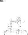
- the electric power steering device (EPS) (1) includes: a steering shaft (shaft) (3) connected to a steering wheel (2) as a steering component; and a rack shaft (6) having a pinion gear (4) disposed on an end of the steering shaft (3) and a rack gear (5) engaged with the pinion gear (4), where the rack shaft (6) can serve as a steering shaft extended in a lateral direction of the vehicle.
- the rack shaft (6) has tie rods (7) connected to both ends thereof, respectively, and the tie rods (7) are connected to their respective wheels (8) through their respective knuckle arms (not shown).
- the steering wheel (2) is manipulated so as to rotate the steering shaft (3), the rotational motion of the steering shaft (3) is converted by the pinion gear (4) and the rack gear (5) to the translational motion of the rack shaft (6) in a lateral direction of the vehicle.
- the steering of the wheels (8) can be thus achieved.
- the steering shaft (3) is separated into an input shaft (9) connected to the steering wheel (2) and an output shaft (10) connected to the pinion gear (4).
- Such input/output shafts (9, 10) are coupled to each other via a torsion bar (11) along the same axis.
- a torque sensor (12) is provided so as to detect steering torque on the basis of an amount of relative rotational displacement between the input and output shafts (9, 10) with respect to the torsion bar (11) interposed therebetween, and output torque-detection results obtained by the torque sensor (12) to a control unit (13).
- the control unit (13) controls a driver (14) so as to adjust a voltage applied to an electric motor (15) for assistance in steering. Still further, the rotation of a rotary shaft (not shown) in the electric motor (15) is decreased in speed through a speed reducer (17). The outputted rotational motion of the speed reducer (17) is converted through a converter (18) to the translational motion of the rack shaft (6) in an axial direction, thereby resulting in assistance in steering.
- This electric power steering device (1) is that of the so-called rack assist type.
- the shaft structure in an embodiment described above is applied e.g. to the steering shaft (3) described above (hereinafter, occasionally referred to as “shaft (3)" for short).
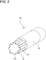
- the shaft structure (20) is installed on a shaft 3 capable of making a power-transmission.
- the male and female components capable of making a power-transmission are slidably fitted with respect to each other in an axial direction, thereby making up such a shaft structure (20).
- the shaft structure (20) as shown in FIG. 2 , includes a metallic male component (21), a metallic female component (22), and a fabric (23) impregnated with rubber or other material.
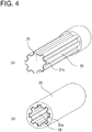
- the male component (21), as shown in (a) of FIG. 3 , has a substantially cylindrical linchpin (21a) and a convex part (21b) projecting from the end of the linchpin (21a).
- the outer peripheral part (21c) of the convex part (21b) has e.g. eight male splines (21d) positioned at predetermined intervals in a circumferential direction around the convex part (21b).
- the female component (22), as shown in (b) of FIG. 3 , is formed into a substantially cylindrical shape and has an inner peripheral part (22a) configured such that the male component (21) can be inserted thereinto, and its outer peripheral part (21c) can be engaged therein.
- the inner peripheral part (22a) of the female component (22) has the structure of eight female splines (22b) (the number of the splines must be the same as that of the male splines on the convex part (21b) of the male component (21), therefore eight (8) in this embodiment) positioned at predetermined intervals in a circumferential direction around the female component (22).
- the fabric (23) may be made of, e.g., aramid fiber, nylon, urethane, cotton, silk, linen, acetate, rayon, fluorine-containing fiber, polyester, and the like, which are impregnated with rubber or resin.
- the fabric (23) may be made of e.g. short fibers or long fibers, and may also be sheet-like fabric.
- the rubber is required to be that with which the fibers can be impregnated.
- types of rubber the followings may be used in a neat form or in a form denatured in various ways: e.g., urethane rubber, nitrile rubber, silicon rubber, fluororubber, acrylic rubber, ethylene-propylene rubber, butyl rubber, isoprene rubber, chlorinated polyethylene rubber, epichlorohydrin rubber, hydrogenated nitrile rubber, chloroprene rubber, polybutadiene rubber, styrene-butadiene rubber, natural rubber, and the like.
- urethane rubber e.g., urethane rubber, nitrile rubber, silicon rubber, fluororubber, acrylic rubber, ethylene-propylene rubber, butyl rubber, isoprene rubber, chlorinated polyethylene rubber, epichlorohydrin rubber, hydrogenated nitrile rubber, chloroprene rubber, polybutadiene rubber, styrene
- the rubber may contain appropriate amounts of traditional compounding ingredients for rubber, such as vulcanizing agent, vulcanizing accelerator, antioxidant, softener, plasticizer, filler, colorant, and the like as well as solid lubricants such as graphite, silicone oil, fluorine powder, molybdenum disulfide, or the like for enhancing the lubricity of the fabric (23).
- traditional compounding ingredients for rubber such as vulcanizing agent, vulcanizing accelerator, antioxidant, softener, plasticizer, filler, colorant, and the like
- solid lubricants such as graphite, silicone oil, fluorine powder, molybdenum disulfide, or the like for enhancing the lubricity of the fabric (23).
- thermoplastic or thermosetting resin such as acrylic resin, polyester resin, urethane resin, vinyl chloride resin, polypropylene, polycarbonate, polyethylene terephthalate resin, fluorine resin, polyethylene, acrylonitrile-styrene resin, acrylonitrile-butadiene-styrene resin, polystyrene resin, polyvinyl chloride, polyvinylidene chloride, polyvinyl acetate, nylon, alkyd resin, phenolic resin, epoxy resin, polyphenylene sulfide resin, and the like.
- thermoplastic or thermosetting resin such as acrylic resin, polyester resin, urethane resin, vinyl chloride resin, polypropylene, polycarbonate, polyethylene terephthalate resin, fluorine resin, polyethylene, acrylonitrile-styrene resin, acrylonitrile-butadiene-styrene resin, polystyrene resin, polyvinyl chloride, polyvinylidene chloride, polyvin
- the rubber or resin be dissolved by a solvent or another means into a liquid state before dipping the predetermined fibers (short or long fibers) in the liquid.
- the sheet-like fabric made of the fibers may be used. This fabric is impregnated with rubber or resin in the same way as described above.
- the fabric may be, e.g., non-woven fabric made of irregularly tangled fibers, regularly-formed woven, knitted fabric, or the like. These fabrics are characterized by facilitating impregnation (easier handling) with rubber and the like, and further facilitating adhesion to the surface of the shaft structure described below in comparison with those made of fibers (short or long fibers) only, because these fabrics are in sheet form.
- the woven fabric may be made in a plain weave, satin weave, twill weave, or the like.
- the fabric may preferably be stretchy to some extent.
- stretchiness when the fabric is formed so as to be in line with the female splines (22b) or male splines (21d) in shape, or when the fabric is adhered to a concave-convex surface of the outer peripheral part (21c) of the male component (21) and the inner peripheral part (22a) of the female component (22), there can be achieved the advantageous effects that: the surface of the fabric can easily be shaped in accordance with the concave-convex surface form; and the fabric (23) has the surface subjected to few creases and uniformly finished, thereby enabling smooth fitting between the male component (21) and the female component (22), and further enabling decrease in sliding resistance generated between: the male component (21) or the female component (22); and the fabric (23).
- the impregnation-processed fabric (23) is interposed between the outer peripheral part (21c) of the male component (21) and the inner peripheral part (22a) of the female component (22) (see (b) of FIG. 3 ).
- the impregnation-processed fabric (23) has an inner surface (23a) substantially the same in shape as the outer peripheral part (21c) of the male component (21) (see (a) of FIG. 3 ), and has an outer surface (23b) substantially the same in shape as the inner peripheral part (22a) of the female component (22) (see (b) of FIG. 3 ).
- the impregnation-processed fabric (23) has an inner surface (23a) substantially the same in shape as the outer peripheral part (21c) of the male component (21) (see (a) of FIG. 3 ), and has an outer surface (23b) substantially the same in shape as the inner peripheral part (22a) of the female component (22) (see (b) of FIG. 3 ).
- the adhesive used here may be, e.g., acrylic resin adhesive, olefin adhesive, urethane resin adhesive, ethylene-vinyl acetate resin adhesive, epoxy resin adhesive, vinyl chloride resin adhesive, chloroprene rubber adhesive, cyanoacrylate adhesive, silicon adhesive, styrene-butadiene rubber adhesive, nitrile rubber adhesive, hot-melt adhesive, phenolic resin adhesive, melamine resin adhesive, urea resin adhesive, resorcinol adhesive, and the like.
- the impregnation-processed fabric (23) is disposed on an entire circumference of the outer peripheral part (21c) of the male component (21).
- the male component (21) adhered with the fabric (23) has a tip projecting from one end of the female component (22) in an axial direction.
- the tip of the male component (21) is processed appropriately in accordance with circumstances that the shaft structure (20) is used.
- the shaft structure (20) can be manufactured by sequentially performing the steps of e.g.: cutting the male and female components (21, 22) having their respective shapes as shown in (a), (b) of FIG. 3 from metal material (not shown); impregnating the fabric (23) with rubber or the like; and interposing the impregnation-processed fabric (23) between the outer peripheral part (21c) of the male component (21) and the inner peripheral part (22a) of the female component (22).
- inner and outer molds for forming the inner and outer surfaces (23a, 23b), respectively are prepared. It is a matter of course that the outer surface of the inner mold and the inner surface of the outer mold have a concave-convex form corresponding to the inner and outer surfaces (23a, 23b), respectively. Fibers (short fibers, long fibers, or sheet-like fabric) impregnated with rubber or resin are stuffed between the inner and outer molds, and thereafter the stuffed fibers are pressed and heated through the molds. Subsequently, the fibers are removed from between the molds. Still subsequently, fabrics (23) having inner and outer surfaces (23a, 23b) molded can be obtained.
- an alternative method of manufacturing the fabric (23) may also be formed by: initially making a fabric supposed to fill a gap between an inner mold and an outer mold into a cylindrical shape in accordance with an outer shape of the inner mold; subsequently disposing the cylindrically-shaped fabric on the inner mold in accordance with the outer shape of the inner mold; and thereafter pressing and heating the fabric placed on the inner mold in a similar manner to the above.
- the stretchiness of the fabric enables the fabric (23) to be formed further in accordance with the concave-convex form of the inner and outer molds.
- the formed fabric (23) having the inner and outer surfaces (23a, 23b) subjected to no creases and uniformly finished can be manufactured.
- the fabric (23) with such uniformly finished surfaces interposed between the male and female components (21, 22) of the shaft structure (20) can result in further decrease in sliding resistance in an axial direction.
- the fabric By forming the fabric into a cylindrical shape in such a manner that a stretchiness direction of the fabric to be formed is aligned at least with a circumferential direction of the formed fabric (23) in a cylindrical shape, the occurrence of creases can be further reduced.
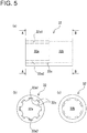
- the male component (21) having the outer peripheral part (21c) adhered with the impregnation-processed fabric (23) as shown in (a) of FIG. 4 can be manufactured by performing the following steps, on condition that "the inner mold” in the above-described manufacturing method is replaced with “the male component (21)”: the step of applying adhesive on a metal surface of the male component (21); the step of subsequently filling fibers (short fibers, long fibers, or sheet-like fabric) impregnated with rubber or resin between the male component (21) and the outer mold; the step of still subsequently pressing and heating the fibers through the outer mold; and thereafter the step of removing the outer mold, thereby obtaining the male component (21) having the outer peripheral part (21c) adhered with the fabric (23) as shown in (a) of FIG.
- the component shown in (a) of FIG. 4 may be obtained by: initially making a fabric into a cylindrical shape in accordance with an outer shape of the male component (21); subsequently disposing the cylindrically-shaped fabric on the male component (21) in accordance with the outer shape thereof; and thereafter pressing the fabric placed on the male component (21).
- the surface of the fabric (23) adhered to the outer peripheral part (21c) of the male component (21) is resistant to the generation of creases, and is uniformly finished, which results in still further decrease in sliding resistance in an axial direction between the male and female components (21, 22) of the shaft structure (20).
- the fabric (23) By forming the fabric (23) into a cylindrical shape in such a manner that a stretchiness direction of the fabric to be formed is aligned at least with a circumferential direction of the male component (21), the occurrence of creases can be further reduced as described above.
- JIS Japanese Industrial Standards
- the present invention shall not be limited to this example. More specifically, the inventors have conducted the Pico abrasion test (JIS K 6264-2) as well as the friction coefficient measurement test (JIS K 7125) using a Heidon tester to compare between nylon 66 impregnated with nitrile rubber and single-component rubber material made of nitrile rubber (hardness 70, JIS K 6253, Type A Durometer).
- Table 1 below shows the results of the Pico abrasion test
- Table 2 below shows the results of the friction coefficient measurement test.
- the item “Rubber-impregnated” denotes material contained in the fabric (23) in this embodiment, more specifically, the nylon 66 impregnated with nitrile rubber
- the item “Single-component rubber” denotes the single-component rubber material made of nitrile rubber for comparison with the material contained in the fabric (23) in this embodiment.
- Table 1 Abrasion loss Rubber-impregnated 2.2 mg Single-component rubber 9.9 mg
- the abrasion loss is 2.2 mg in the nylon 66 impregnated with nitrile rubber, and is 9.9 mg in the single-component rubber material made of nitrile rubber. It is therefore found that the abrasion loss can be reduced to approximately one-fifth in the nylon 66 impregnated with nitrile rubber as compared to the single-component rubber material.
- the friction coefficient is 0.54 in the nylon 66 impregnated with nitrile rubber, and is 1.48 in the single-component rubber material made of nitrile rubber. It is found therefore that the friction coefficient can be reduced to approximately one-third in the nylon 66 impregnated with nitrile rubber as compared to the single-component rubber material.
- the fabric (23) containing the nylon 66 impregnated with nitrile rubber formed on the outer peripheral part (21c) of the male component (21) can reduce the sliding resistance (the friction coefficient is decreased more than that of the single-component rubber material formed on the outer peripheral part (21c) of the male component (21)), and can improve the durability (the abrasion loss is decreased further than that of the single-component rubber material formed on the outer peripheral part (21c) of the male component (21)).
- the need for lubrication between the outer peripheral part (21c) of the male component (21) and the inner peripheral part (22a) of the female component (22) can be eliminated, and expense in time and effort can be saved with respect to the need for lubricant supply.
- the resistance to wear on the surface of the fabric (23) caused by friction between the fabric (23) and the outer peripheral part (21c) of the male component (21) or between the fabric (23) and the inner peripheral part (22a) of the female component (22) can be improved.
- Means for interposing the rubber-impregnated fabric (23) between the outer peripheral part (21c) of the male component (21) and the inner peripheral part (22a) of the female component (22) are not limited to one sort of means shown in (a) of FIG. 4 , by which the fabric (23) impregnated with rubber is adhered to the outer peripheral part (21c) of the male component (21).
- Another sort of means available is shown in (b) of FIG. 4 , by which the fabric (23) impregnated with rubber is adhered to the inner peripheral part (22a) of the female component (22).
- the rubber-impregnated fabric (23) can be adhered to the outer peripheral part (21c) of the male component (21) or the inner peripheral part (22a) of the female component (22) by: forming a rubber layer on a rear surface (a surface to be adhered to the outer peripheral part (21c) of the male component (21) or the inner peripheral part (22a) of the female component (22)) of the rubber-impregnated fabric (23) such that the rubber layer is integrated with the fabric (23); and subsequently adhering the rubber layer with adhesive to a metal surface (a surface of the outer peripheral part (21c) of the male component (21) or the inner peripheral part (22a) of the female component (22)), for example. According to such means, the adhesion between the fabric (23) and the metal surface can be strengthen.
- the female component (22) in the above embodiment may be replaced by a female component (32) shown in FIG. 5 ((a) a side view; (b) a view taken along an arrowed line A-A of (a); and (c) a view taken along an arrowed line B-B of (a)).
- the female component (32) will be specifically described. Note that, in (a) of FIG. 5 , a transparent view is provided only for the parts (32a1, 32a2) by using a dashed-dotted line for convenience in the illustration.
- the female component (32) includes a first hole (32a), a second hole (32b), and a movement stopper (32c) (first movement stopper).
- the first hole (32a) is configured such that, when a male component like the male component (21) in the above embodiment is inserted into the first hole (32a), the male component slidably fits in the inner peripheral part of the first hole (32a) (e.g. parts 32a1 and 32a2) along the first hole (32a), and the male component is caused by the movement stopper (32c) to stop moving before or at a predetermined position (at a bottom of the first hole (32a)).
- a fabric like the fabric (23) in the above embodiment is interposed between the male component and the first hole (32a).
- the second hole (32b) is configured in a cylindrical shape such that a rod-shaped component (not shown) having a predetermined diameter can be pressed in and fixed to the second hole (32b).
- the female component (32) can be used as a component for connecting (coupling) the male component, which is the same in sort as the male component (21), and the rod-shaped component.
- the movement stopper (32c) in particular enables the female component (32) itself to be positioned between the male component and the rod-shaped component.
- the female component (22) in the above embodiment may be replaced by a female component (42) shown in FIG. 6 ((a) a side view; (b) a view taken along an arrowed line C-C of (a); and (c) a view taken along an arrowed line D-D of (a)).
- the female component (42) will be specifically described. Note that, in (a) of FIG. 6 , a transparent view is provided only for the parts (42a1, 42a2, 42b1, 42b2) by using a dashed-dotted line for convenience in illustration.
- the female component (42) includes a third hole (42a), a fourth hole (42b), a movement stopper (42c) (second movement stopper), and a movement stopper (42d) (third movement stopper).
- the third hole (42a) is configured such that, when a male component like the male component (21) in the above embodiment is inserted into the third hole (42a), the male component slidably fits in the inner peripheral part of the third hole (42a) (e.g. parts 42a1 and 42a2) along the third hole (42a), and the male component is caused by the movement stopper (42c) to stop moving before or at a predetermined position (at a bottom of the third hole (42a)).
- a fabric like the fabric (23) in the above embodiment is interposed between the male component and the third hole (42a).
- the fourth hole (42b) is configured such that, when another male component (not shown) like the male component (21) in the above embodiment is inserted into the fourth hole (42b), the male component slidably fits in the inner peripheral part of the fourth hole (42b) (e.g. parts 42b1 and 42b2) along the fourth hole (42a), and the male component is caused by the movement stopper (42d) to stop moving before or at a predetermined position (at a bottom of the fourth hole (42b)).
- a fabric like the fabric (23) in the above embodiment is interposed between the male component and the fourth hole (42b).
- the female component (42) can be used as a component for connecting (coupling) the male component, which is the same in sort as the male component (21), and another male component.
- the movement stoppers (42c, 42d) in particular enable the female component (42) itself to be positioned between the male component, which is the same in sort as the male component (21), and the above-described another male component.
- shaft structures in the above embodiments and modified examples 1, 2 are applied to the steering shafts for vehicles, the present invention can be applied not only to such shafts in a limitative manner but also to shafts used for various industrial machines.
- each movement stopper at the bottom of each hole may be arranged anywhere in the holes as long as they can stop the movement of the male component before or at a predetermined position (arbitrarily defined positions) in the holes so as to determine the position of the female component.
Landscapes
- Engineering & Computer Science (AREA)
- General Engineering & Computer Science (AREA)
- Mechanical Engineering (AREA)
- Ocean & Marine Engineering (AREA)
- Chemical & Material Sciences (AREA)
- Combustion & Propulsion (AREA)
- Transportation (AREA)
- Power Steering Mechanism (AREA)
- Shafts, Cranks, Connecting Bars, And Related Bearings (AREA)
- Reinforced Plastic Materials (AREA)
Applications Claiming Priority (4)
| Application Number | Priority Date | Filing Date | Title |
|---|---|---|---|
| JP2012137828 | 2012-06-19 | ||
| JP2012219686A JP6232182B2 (ja) | 2012-10-01 | 2012-10-01 | シャフト用構造体、雄型部材、及び、雌型部材 |
| JP2013117482A JP6196813B2 (ja) | 2012-06-19 | 2013-06-04 | シャフト用構造体、雄型部材、及び、雌型部材 |
| PCT/JP2013/066556 WO2013191123A1 (ja) | 2012-06-19 | 2013-06-17 | シャフト用構造体、雄型部材、及び、雌型部材 |
Publications (3)
| Publication Number | Publication Date |
|---|---|
| EP2863084A1 EP2863084A1 (en) | 2015-04-22 |
| EP2863084A4 EP2863084A4 (en) | 2016-09-07 |
| EP2863084B1 true EP2863084B1 (en) | 2018-07-25 |
Family
ID=50549932
Family Applications (1)
| Application Number | Title | Priority Date | Filing Date |
|---|---|---|---|
| EP13807294.7A Not-in-force EP2863084B1 (en) | 2012-06-19 | 2013-06-17 | Structural body for shaft, male member, and female member |
Country Status (8)
| Country | Link |
|---|---|
| US (1) | US10344795B2 (zh) |
| EP (1) | EP2863084B1 (zh) |
| KR (1) | KR20150031274A (zh) |
| CN (1) | CN104379954B (zh) |
| ES (1) | ES2687703T3 (zh) |
| IN (1) | IN2015MN00046A (zh) |
| TW (1) | TWI577900B (zh) |
| WO (1) | WO2013191123A1 (zh) |
Families Citing this family (12)
| Publication number | Priority date | Publication date | Assignee | Title |
|---|---|---|---|---|
| JP6229885B2 (ja) * | 2014-01-21 | 2017-11-15 | 株式会社ジェイテクト | 伸縮軸の製造方法 |
| JP2016033384A (ja) * | 2014-07-31 | 2016-03-10 | ニッタ株式会社 | シャフト用構造体、雄型部材、及び雌型部材 |
| DE102016107997A1 (de) * | 2016-04-29 | 2017-11-02 | Weber Maschinenbau Gmbh Breidenbach | Fördereinheit |
| CN106009677B (zh) * | 2016-07-18 | 2018-06-26 | 深圳市尚智工程技术咨询有限公司 | 一种纳米导电橡胶传感单元及其制备方法 |
| DE102017103779B4 (de) * | 2017-02-23 | 2021-01-21 | Vibracoustic Gmbh | Elastisches Lager |
| US10414426B2 (en) * | 2017-08-14 | 2019-09-17 | Steering Solutions Ip Holding Corporation | Steering shaft assembly having a sleeve |
| DE102017221075B4 (de) * | 2017-11-24 | 2019-06-27 | Thyssenkrupp Ag | Lenkwelle für ein Kraftfahrzeug |
| US11084445B2 (en) * | 2019-02-06 | 2021-08-10 | Ford Global Technologies, Llc | Energy-absorbing knee bolster |
| DE102019205784B3 (de) * | 2019-04-23 | 2020-06-25 | Thyssenkrupp Ag | Längenverstellbare Lenkwelle für ein Kraftfahrzeug und Profilhülse für eine Lenkwelle |
| CN111644682A (zh) * | 2020-06-15 | 2020-09-11 | 苏州特鲁利电子材料有限公司 | 一种高精度自动平板切割机 |
| US20220029392A1 (en) * | 2020-07-24 | 2022-01-27 | Sherman + Reilly, Inc. | Line pulling systems and devices |
| CN113931939B (zh) * | 2021-08-31 | 2024-03-29 | 江苏泰克曼传动设备有限公司 | 一种带安全防护功能的联轴器 |
Family Cites Families (29)
| Publication number | Priority date | Publication date | Assignee | Title |
|---|---|---|---|---|
| US1505694A (en) * | 1922-08-19 | 1924-08-19 | Frank T Lahey | Process of rubberizing fabric |
| US2199926A (en) * | 1937-07-19 | 1940-05-07 | Borg Warner | Resilient slip joint |
| US2394448A (en) * | 1942-11-30 | 1946-02-05 | Edgar M D Herold | Drive coupling |
| DE4010694A1 (de) * | 1990-04-03 | 1991-10-10 | Hoechst Ag | Faserverstaerkter werkstoff, verfahren zu seiner herstellung und seine verwendung |
| US5880043A (en) * | 1991-04-03 | 1999-03-09 | Hoechst Aktiengesellschaft | Fiber-reinforced material and production and use thereof |
| JP2956334B2 (ja) | 1991-12-04 | 1999-10-04 | トヨタ自動車株式会社 | スプラインの構造 |
| EP0971142A1 (en) * | 1998-06-17 | 2000-01-12 | The Gates Corporation | Flexible shaft coupling element, flexible couplings incorporating same and method for forming same |
| JP3853150B2 (ja) * | 1999-12-02 | 2006-12-06 | 株式会社ジェイテクト | 伸縮自在シャフト |
| US6283867B1 (en) * | 1999-12-07 | 2001-09-04 | Koyo Seiko Co., Ltd. | Elastic shaft joint |
| US6726228B2 (en) * | 2002-02-25 | 2004-04-27 | General Motors Corporation | Steering wheel alignment system |
| JP3797304B2 (ja) * | 2002-09-13 | 2006-07-19 | 日本精工株式会社 | 車両ステアリング用伸縮軸 |
| JP3958732B2 (ja) * | 2003-10-09 | 2007-08-15 | 三菱電機株式会社 | 回転電機およびその製造方法 |
| JP2007161165A (ja) | 2005-12-15 | 2007-06-28 | Nsk Ltd | 動力伝達機構とこれを組み込んだ電動式パワーステアリング装置 |
| US20070275172A1 (en) * | 2006-05-25 | 2007-11-29 | Cowles Rebecca S | Methods of applying high performance coatings |
| JP5119707B2 (ja) * | 2006-06-29 | 2013-01-16 | 日本精工株式会社 | 伸縮軸 |
| US7625290B2 (en) * | 2006-07-05 | 2009-12-01 | The Gates Corporation | Sleeve-type flexible shaft coupling |
| JP2008120250A (ja) * | 2006-11-13 | 2008-05-29 | Nsk Ltd | 車両ステアリング用伸縮軸 |
| FR2909146B1 (fr) * | 2006-11-28 | 2009-06-05 | Snecma Sa | Dispositif de liaison de deux arbres rotatifs, en particulier dans une turbomachine. |
| JP5003412B2 (ja) * | 2007-10-29 | 2012-08-15 | 日本精工株式会社 | トルク伝達用継手及び電動パワ−ステアリング装置 |
| JP2009257423A (ja) * | 2008-04-15 | 2009-11-05 | Toyota Motor Corp | スプライン連結構造および動力伝達装置 |
| US20090291003A1 (en) * | 2008-05-22 | 2009-11-26 | Baker Hughes Incorporated | Centering coupling for electrical submersible pump splined shafts |
| US8545125B2 (en) * | 2009-06-01 | 2013-10-01 | Baker Hughes Incorporated | Non-parallel splined hub and shaft connection |
| JP5453012B2 (ja) * | 2009-08-07 | 2014-03-26 | 株式会社ジェイテクト | スプライン伸縮軸の製造方法 |
| JP2011038560A (ja) * | 2009-08-07 | 2011-02-24 | Jtekt Corp | スプライン伸縮軸及びその製造方法並びに車両用操舵装置 |
| JP2011111112A (ja) * | 2009-11-30 | 2011-06-09 | Nsk Ltd | 車両ステアリング用伸縮軸 |
| JP2011173463A (ja) | 2010-02-23 | 2011-09-08 | Jtekt Corp | スプライン伸縮軸の製造方法 |
| JP5549658B2 (ja) | 2010-11-18 | 2014-07-16 | 日本精工株式会社 | 伸縮軸の製造方法、及び、この製造方法によって製造した伸縮軸 |
| US8783995B2 (en) * | 2011-02-25 | 2014-07-22 | Deere & Company | Coupler for promoting lubrication of shaft splines |
| KR101271324B1 (ko) * | 2011-06-20 | 2013-06-05 | 주식회사 만도 | 전동식 동력 보조 조향장치의 감속기 |
-
2013
- 2013-06-17 ES ES13807294.7T patent/ES2687703T3/es active Active
- 2013-06-17 IN IN46MUN2015 patent/IN2015MN00046A/en unknown
- 2013-06-17 WO PCT/JP2013/066556 patent/WO2013191123A1/ja active Application Filing
- 2013-06-17 CN CN201380032764.2A patent/CN104379954B/zh not_active Expired - Fee Related
- 2013-06-17 EP EP13807294.7A patent/EP2863084B1/en not_active Not-in-force
- 2013-06-17 KR KR1020157000663A patent/KR20150031274A/ko active Search and Examination
- 2013-06-19 TW TW102121743A patent/TWI577900B/zh not_active IP Right Cessation
-
2014
- 2014-12-18 US US14/575,901 patent/US10344795B2/en not_active Expired - Fee Related
Non-Patent Citations (1)
| Title |
|---|
| None * |
Also Published As
| Publication number | Publication date |
|---|---|
| KR20150031274A (ko) | 2015-03-23 |
| US10344795B2 (en) | 2019-07-09 |
| ES2687703T3 (es) | 2018-10-26 |
| IN2015MN00046A (zh) | 2015-10-16 |
| TWI577900B (zh) | 2017-04-11 |
| WO2013191123A1 (ja) | 2013-12-27 |
| EP2863084A1 (en) | 2015-04-22 |
| US20150110551A1 (en) | 2015-04-23 |
| EP2863084A4 (en) | 2016-09-07 |
| CN104379954B (zh) | 2018-01-02 |
| CN104379954A (zh) | 2015-02-25 |
| TW201405026A (zh) | 2014-02-01 |
Similar Documents
| Publication | Publication Date | Title |
|---|---|---|
| EP2863084B1 (en) | Structural body for shaft, male member, and female member | |
| US9458871B2 (en) | Structure for shaft, male member, and female member | |
| CN104554426B (zh) | 电动辅助转向装置的减速器 | |
| CN106080751A (zh) | 蜗轮减速机以及转向装置 | |
| CN105398490B (zh) | 动力传递轴的制造方法以及车辆用转向操纵装置 | |
| CN106995002B (zh) | 电动助力转向装置的减速器 | |
| CN107031700A (zh) | 转向装置 | |
| CN108974111A (zh) | 转向装置 | |
| US20170138408A1 (en) | Structure for shaft, male member, and female member | |
| CN102666251A (zh) | 伸缩轴的制造方法以及利用该制造方法制造的伸缩轴 | |
| JP2008002630A (ja) | 伸縮軸 | |
| CN106029468B (zh) | 机动车转向装置、用于机动车转向装置的装配辅助工具和装配方法 | |
| JP2016173157A (ja) | 動力伝達軸 | |
| US11148712B2 (en) | Reducer of electric power steering apparatus | |
| JP6196813B2 (ja) | シャフト用構造体、雄型部材、及び、雌型部材 | |
| KR102221057B1 (ko) | 스티어링 장치의 인터미디에이트 샤프트 | |
| KR102207483B1 (ko) | 전동식 파워 스티어링 | |
| JP6232182B2 (ja) | シャフト用構造体、雄型部材、及び、雌型部材 | |
| JP6374813B2 (ja) | 動力伝達軸 | |
| JP6790758B2 (ja) | 電動パワーステアリング装置 | |
| CN106080752B (zh) | 蜗杆轴子组件 | |
| JP6528541B2 (ja) | 伸縮自在シャフト及びその製造方法 | |
| JP2010127425A (ja) | トリポード系ジョイントのハウジング | |
| JP2016223519A5 (zh) | ||
| KR20100024054A (ko) | 차량용 인터미디어트 샤프트 어셈블리 |
Legal Events
| Date | Code | Title | Description |
|---|---|---|---|
| PUAI | Public reference made under article 153(3) epc to a published international application that has entered the european phase |
Free format text: ORIGINAL CODE: 0009012 |
|
| 17P | Request for examination filed |
Effective date: 20150109 |
|
| AK | Designated contracting states |
Kind code of ref document: A1 Designated state(s): AL AT BE BG CH CY CZ DE DK EE ES FI FR GB GR HR HU IE IS IT LI LT LU LV MC MK MT NL NO PL PT RO RS SE SI SK SM TR |
|
| AX | Request for extension of the european patent |
Extension state: BA ME |
|
| DAX | Request for extension of the european patent (deleted) | ||
| RA4 | Supplementary search report drawn up and despatched (corrected) |
Effective date: 20160804 |
|
| RIC1 | Information provided on ipc code assigned before grant |
Ipc: F16D 1/02 20060101ALI20160729BHEP Ipc: F16D 3/06 20060101AFI20160729BHEP |
|
| GRAP | Despatch of communication of intention to grant a patent |
Free format text: ORIGINAL CODE: EPIDOSNIGR1 |
|
| STAA | Information on the status of an ep patent application or granted ep patent |
Free format text: STATUS: GRANT OF PATENT IS INTENDED |
|
| INTG | Intention to grant announced |
Effective date: 20180215 |
|
| GRAS | Grant fee paid |
Free format text: ORIGINAL CODE: EPIDOSNIGR3 |
|
| GRAA | (expected) grant |
Free format text: ORIGINAL CODE: 0009210 |
|
| STAA | Information on the status of an ep patent application or granted ep patent |
Free format text: STATUS: THE PATENT HAS BEEN GRANTED |
|
| AK | Designated contracting states |
Kind code of ref document: B1 Designated state(s): AL AT BE BG CH CY CZ DE DK EE ES FI FR GB GR HR HU IE IS IT LI LT LU LV MC MK MT NL NO PL PT RO RS SE SI SK SM TR |
|
| REG | Reference to a national code |
Ref country code: GB Ref legal event code: FG4D |
|
| REG | Reference to a national code |
Ref country code: CH Ref legal event code: EP |
|
| REG | Reference to a national code |
Ref country code: AT Ref legal event code: REF Ref document number: 1022099 Country of ref document: AT Kind code of ref document: T Effective date: 20180815 |
|
| REG | Reference to a national code |
Ref country code: IE Ref legal event code: FG4D |
|
| REG | Reference to a national code |
Ref country code: DE Ref legal event code: R096 Ref document number: 602013040919 Country of ref document: DE |
|
| REG | Reference to a national code |
Ref country code: SE Ref legal event code: TRGR |
|
| REG | Reference to a national code |
Ref country code: ES Ref legal event code: FG2A Ref document number: 2687703 Country of ref document: ES Kind code of ref document: T3 Effective date: 20181026 |
|
| REG | Reference to a national code |
Ref country code: NL Ref legal event code: MP Effective date: 20180725 |
|
| REG | Reference to a national code |
Ref country code: LT Ref legal event code: MG4D |
|
| PG25 | Lapsed in a contracting state [announced via postgrant information from national office to epo] |
Ref country code: NL Free format text: LAPSE BECAUSE OF FAILURE TO SUBMIT A TRANSLATION OF THE DESCRIPTION OR TO PAY THE FEE WITHIN THE PRESCRIBED TIME-LIMIT Effective date: 20180725 |
|
| REG | Reference to a national code |
Ref country code: AT Ref legal event code: MK05 Ref document number: 1022099 Country of ref document: AT Kind code of ref document: T Effective date: 20180725 |
|
| PG25 | Lapsed in a contracting state [announced via postgrant information from national office to epo] |
Ref country code: FI Free format text: LAPSE BECAUSE OF FAILURE TO SUBMIT A TRANSLATION OF THE DESCRIPTION OR TO PAY THE FEE WITHIN THE PRESCRIBED TIME-LIMIT Effective date: 20180725 Ref country code: RS Free format text: LAPSE BECAUSE OF FAILURE TO SUBMIT A TRANSLATION OF THE DESCRIPTION OR TO PAY THE FEE WITHIN THE PRESCRIBED TIME-LIMIT Effective date: 20180725 Ref country code: IS Free format text: LAPSE BECAUSE OF FAILURE TO SUBMIT A TRANSLATION OF THE DESCRIPTION OR TO PAY THE FEE WITHIN THE PRESCRIBED TIME-LIMIT Effective date: 20181125 Ref country code: AT Free format text: LAPSE BECAUSE OF FAILURE TO SUBMIT A TRANSLATION OF THE DESCRIPTION OR TO PAY THE FEE WITHIN THE PRESCRIBED TIME-LIMIT Effective date: 20180725 Ref country code: LT Free format text: LAPSE BECAUSE OF FAILURE TO SUBMIT A TRANSLATION OF THE DESCRIPTION OR TO PAY THE FEE WITHIN THE PRESCRIBED TIME-LIMIT Effective date: 20180725 Ref country code: NO Free format text: LAPSE BECAUSE OF FAILURE TO SUBMIT A TRANSLATION OF THE DESCRIPTION OR TO PAY THE FEE WITHIN THE PRESCRIBED TIME-LIMIT Effective date: 20181025 Ref country code: PL Free format text: LAPSE BECAUSE OF FAILURE TO SUBMIT A TRANSLATION OF THE DESCRIPTION OR TO PAY THE FEE WITHIN THE PRESCRIBED TIME-LIMIT Effective date: 20180725 Ref country code: GR Free format text: LAPSE BECAUSE OF FAILURE TO SUBMIT A TRANSLATION OF THE DESCRIPTION OR TO PAY THE FEE WITHIN THE PRESCRIBED TIME-LIMIT Effective date: 20181026 Ref country code: BG Free format text: LAPSE BECAUSE OF FAILURE TO SUBMIT A TRANSLATION OF THE DESCRIPTION OR TO PAY THE FEE WITHIN THE PRESCRIBED TIME-LIMIT Effective date: 20181025 |
|
| PG25 | Lapsed in a contracting state [announced via postgrant information from national office to epo] |
Ref country code: AL Free format text: LAPSE BECAUSE OF FAILURE TO SUBMIT A TRANSLATION OF THE DESCRIPTION OR TO PAY THE FEE WITHIN THE PRESCRIBED TIME-LIMIT Effective date: 20180725 Ref country code: HR Free format text: LAPSE BECAUSE OF FAILURE TO SUBMIT A TRANSLATION OF THE DESCRIPTION OR TO PAY THE FEE WITHIN THE PRESCRIBED TIME-LIMIT Effective date: 20180725 Ref country code: LV Free format text: LAPSE BECAUSE OF FAILURE TO SUBMIT A TRANSLATION OF THE DESCRIPTION OR TO PAY THE FEE WITHIN THE PRESCRIBED TIME-LIMIT Effective date: 20180725 |
|
| REG | Reference to a national code |
Ref country code: DE Ref legal event code: R097 Ref document number: 602013040919 Country of ref document: DE |
|
| PG25 | Lapsed in a contracting state [announced via postgrant information from national office to epo] |
Ref country code: EE Free format text: LAPSE BECAUSE OF FAILURE TO SUBMIT A TRANSLATION OF THE DESCRIPTION OR TO PAY THE FEE WITHIN THE PRESCRIBED TIME-LIMIT Effective date: 20180725 Ref country code: CZ Free format text: LAPSE BECAUSE OF FAILURE TO SUBMIT A TRANSLATION OF THE DESCRIPTION OR TO PAY THE FEE WITHIN THE PRESCRIBED TIME-LIMIT Effective date: 20180725 Ref country code: RO Free format text: LAPSE BECAUSE OF FAILURE TO SUBMIT A TRANSLATION OF THE DESCRIPTION OR TO PAY THE FEE WITHIN THE PRESCRIBED TIME-LIMIT Effective date: 20180725 |
|
| PG25 | Lapsed in a contracting state [announced via postgrant information from national office to epo] |
Ref country code: DK Free format text: LAPSE BECAUSE OF FAILURE TO SUBMIT A TRANSLATION OF THE DESCRIPTION OR TO PAY THE FEE WITHIN THE PRESCRIBED TIME-LIMIT Effective date: 20180725 Ref country code: SM Free format text: LAPSE BECAUSE OF FAILURE TO SUBMIT A TRANSLATION OF THE DESCRIPTION OR TO PAY THE FEE WITHIN THE PRESCRIBED TIME-LIMIT Effective date: 20180725 Ref country code: SK Free format text: LAPSE BECAUSE OF FAILURE TO SUBMIT A TRANSLATION OF THE DESCRIPTION OR TO PAY THE FEE WITHIN THE PRESCRIBED TIME-LIMIT Effective date: 20180725 |
|
| PLBE | No opposition filed within time limit |
Free format text: ORIGINAL CODE: 0009261 |
|
| STAA | Information on the status of an ep patent application or granted ep patent |
Free format text: STATUS: NO OPPOSITION FILED WITHIN TIME LIMIT |
|
| 26N | No opposition filed |
Effective date: 20190426 |
|
| PGFP | Annual fee paid to national office [announced via postgrant information from national office to epo] |
Ref country code: DE Payment date: 20190619 Year of fee payment: 7 Ref country code: IT Payment date: 20190624 Year of fee payment: 7 |
|
| PG25 | Lapsed in a contracting state [announced via postgrant information from national office to epo] |
Ref country code: SI Free format text: LAPSE BECAUSE OF FAILURE TO SUBMIT A TRANSLATION OF THE DESCRIPTION OR TO PAY THE FEE WITHIN THE PRESCRIBED TIME-LIMIT Effective date: 20180725 |
|
| PGFP | Annual fee paid to national office [announced via postgrant information from national office to epo] |
Ref country code: SE Payment date: 20190619 Year of fee payment: 7 Ref country code: FR Payment date: 20190619 Year of fee payment: 7 |
|
| PGFP | Annual fee paid to national office [announced via postgrant information from national office to epo] |
Ref country code: ES Payment date: 20190722 Year of fee payment: 7 Ref country code: GB Payment date: 20190619 Year of fee payment: 7 |
|
| PG25 | Lapsed in a contracting state [announced via postgrant information from national office to epo] |
Ref country code: MC Free format text: LAPSE BECAUSE OF FAILURE TO SUBMIT A TRANSLATION OF THE DESCRIPTION OR TO PAY THE FEE WITHIN THE PRESCRIBED TIME-LIMIT Effective date: 20180725 |
|
| REG | Reference to a national code |
Ref country code: CH Ref legal event code: PL |
|
| REG | Reference to a national code |
Ref country code: BE Ref legal event code: MM Effective date: 20190630 |
|
| PG25 | Lapsed in a contracting state [announced via postgrant information from national office to epo] |
Ref country code: TR Free format text: LAPSE BECAUSE OF FAILURE TO SUBMIT A TRANSLATION OF THE DESCRIPTION OR TO PAY THE FEE WITHIN THE PRESCRIBED TIME-LIMIT Effective date: 20180725 |
|
| PG25 | Lapsed in a contracting state [announced via postgrant information from national office to epo] |
Ref country code: IE Free format text: LAPSE BECAUSE OF NON-PAYMENT OF DUE FEES Effective date: 20190617 |
|
| PG25 | Lapsed in a contracting state [announced via postgrant information from national office to epo] |
Ref country code: BE Free format text: LAPSE BECAUSE OF NON-PAYMENT OF DUE FEES Effective date: 20190630 Ref country code: CH Free format text: LAPSE BECAUSE OF NON-PAYMENT OF DUE FEES Effective date: 20190630 Ref country code: LU Free format text: LAPSE BECAUSE OF NON-PAYMENT OF DUE FEES Effective date: 20190617 Ref country code: LI Free format text: LAPSE BECAUSE OF NON-PAYMENT OF DUE FEES Effective date: 20190630 |
|
| PG25 | Lapsed in a contracting state [announced via postgrant information from national office to epo] |
Ref country code: PT Free format text: LAPSE BECAUSE OF FAILURE TO SUBMIT A TRANSLATION OF THE DESCRIPTION OR TO PAY THE FEE WITHIN THE PRESCRIBED TIME-LIMIT Effective date: 20181125 |
|
| REG | Reference to a national code |
Ref country code: DE Ref legal event code: R119 Ref document number: 602013040919 Country of ref document: DE |
|
| GBPC | Gb: european patent ceased through non-payment of renewal fee |
Effective date: 20200617 |
|
| PG25 | Lapsed in a contracting state [announced via postgrant information from national office to epo] |
Ref country code: GB Free format text: LAPSE BECAUSE OF NON-PAYMENT OF DUE FEES Effective date: 20200617 Ref country code: FR Free format text: LAPSE BECAUSE OF NON-PAYMENT OF DUE FEES Effective date: 20200630 |
|
| PG25 | Lapsed in a contracting state [announced via postgrant information from national office to epo] |
Ref country code: DE Free format text: LAPSE BECAUSE OF NON-PAYMENT OF DUE FEES Effective date: 20210101 Ref country code: CY Free format text: LAPSE BECAUSE OF FAILURE TO SUBMIT A TRANSLATION OF THE DESCRIPTION OR TO PAY THE FEE WITHIN THE PRESCRIBED TIME-LIMIT Effective date: 20180725 Ref country code: SE Free format text: LAPSE BECAUSE OF NON-PAYMENT OF DUE FEES Effective date: 20200618 |
|
| PG25 | Lapsed in a contracting state [announced via postgrant information from national office to epo] |
Ref country code: HU Free format text: LAPSE BECAUSE OF FAILURE TO SUBMIT A TRANSLATION OF THE DESCRIPTION OR TO PAY THE FEE WITHIN THE PRESCRIBED TIME-LIMIT; INVALID AB INITIO Effective date: 20130617 Ref country code: MT Free format text: LAPSE BECAUSE OF FAILURE TO SUBMIT A TRANSLATION OF THE DESCRIPTION OR TO PAY THE FEE WITHIN THE PRESCRIBED TIME-LIMIT Effective date: 20180725 |
|
| REG | Reference to a national code |
Ref country code: SE Ref legal event code: EUG |
|
| PG25 | Lapsed in a contracting state [announced via postgrant information from national office to epo] |
Ref country code: IT Free format text: LAPSE BECAUSE OF NON-PAYMENT OF DUE FEES Effective date: 20200617 |
|
| REG | Reference to a national code |
Ref country code: ES Ref legal event code: FD2A Effective date: 20211103 |
|
| PG25 | Lapsed in a contracting state [announced via postgrant information from national office to epo] |
Ref country code: ES Free format text: LAPSE BECAUSE OF NON-PAYMENT OF DUE FEES Effective date: 20200618 |
|
| PG25 | Lapsed in a contracting state [announced via postgrant information from national office to epo] |
Ref country code: MK Free format text: LAPSE BECAUSE OF FAILURE TO SUBMIT A TRANSLATION OF THE DESCRIPTION OR TO PAY THE FEE WITHIN THE PRESCRIBED TIME-LIMIT Effective date: 20180725 |