EP2862671A1 - Device for processing bar-shaped profile blanks - Google Patents
Device for processing bar-shaped profile blanks Download PDFInfo
- Publication number
- EP2862671A1 EP2862671A1 EP20130188735 EP13188735A EP2862671A1 EP 2862671 A1 EP2862671 A1 EP 2862671A1 EP 20130188735 EP20130188735 EP 20130188735 EP 13188735 A EP13188735 A EP 13188735A EP 2862671 A1 EP2862671 A1 EP 2862671A1
- Authority
- EP
- European Patent Office
- Prior art keywords
- plane
- processing
- tool
- profile
- movable
- Prior art date
- Legal status (The legal status is an assumption and is not a legal conclusion. Google has not performed a legal analysis and makes no representation as to the accuracy of the status listed.)
- Withdrawn
Links
Images


Classifications
-
- B—PERFORMING OPERATIONS; TRANSPORTING
- B23—MACHINE TOOLS; METAL-WORKING NOT OTHERWISE PROVIDED FOR
- B23Q—DETAILS, COMPONENTS, OR ACCESSORIES FOR MACHINE TOOLS, e.g. ARRANGEMENTS FOR COPYING OR CONTROLLING; MACHINE TOOLS IN GENERAL CHARACTERISED BY THE CONSTRUCTION OF PARTICULAR DETAILS OR COMPONENTS; COMBINATIONS OR ASSOCIATIONS OF METAL-WORKING MACHINES, NOT DIRECTED TO A PARTICULAR RESULT
- B23Q39/00—Metal-working machines incorporating a plurality of sub-assemblies, each capable of performing a metal-working operation
- B23Q39/02—Metal-working machines incorporating a plurality of sub-assemblies, each capable of performing a metal-working operation the sub-assemblies being capable of being brought to act at a single operating station
- B23Q39/021—Metal-working machines incorporating a plurality of sub-assemblies, each capable of performing a metal-working operation the sub-assemblies being capable of being brought to act at a single operating station with a plurality of toolheads per workholder, whereby the toolhead is a main spindle, a multispindle, a revolver or the like
- B23Q39/025—Metal-working machines incorporating a plurality of sub-assemblies, each capable of performing a metal-working operation the sub-assemblies being capable of being brought to act at a single operating station with a plurality of toolheads per workholder, whereby the toolhead is a main spindle, a multispindle, a revolver or the like with different working directions of toolheads on same workholder
- B23Q39/026—Metal-working machines incorporating a plurality of sub-assemblies, each capable of performing a metal-working operation the sub-assemblies being capable of being brought to act at a single operating station with a plurality of toolheads per workholder, whereby the toolhead is a main spindle, a multispindle, a revolver or the like with different working directions of toolheads on same workholder simultaneous working of toolheads
-
- B—PERFORMING OPERATIONS; TRANSPORTING
- B23—MACHINE TOOLS; METAL-WORKING NOT OTHERWISE PROVIDED FOR
- B23Q—DETAILS, COMPONENTS, OR ACCESSORIES FOR MACHINE TOOLS, e.g. ARRANGEMENTS FOR COPYING OR CONTROLLING; MACHINE TOOLS IN GENERAL CHARACTERISED BY THE CONSTRUCTION OF PARTICULAR DETAILS OR COMPONENTS; COMBINATIONS OR ASSOCIATIONS OF METAL-WORKING MACHINES, NOT DIRECTED TO A PARTICULAR RESULT
- B23Q39/00—Metal-working machines incorporating a plurality of sub-assemblies, each capable of performing a metal-working operation
- B23Q2039/004—Machines with tool turrets
-
- B—PERFORMING OPERATIONS; TRANSPORTING
- B23—MACHINE TOOLS; METAL-WORKING NOT OTHERWISE PROVIDED FOR
- B23Q—DETAILS, COMPONENTS, OR ACCESSORIES FOR MACHINE TOOLS, e.g. ARRANGEMENTS FOR COPYING OR CONTROLLING; MACHINE TOOLS IN GENERAL CHARACTERISED BY THE CONSTRUCTION OF PARTICULAR DETAILS OR COMPONENTS; COMBINATIONS OR ASSOCIATIONS OF METAL-WORKING MACHINES, NOT DIRECTED TO A PARTICULAR RESULT
- B23Q2240/00—Machine tools specially suited for a specific kind of workpiece
- B23Q2240/007—Elongated workpieces
Definitions
- the invention relates to a device for processing rod-shaped profile blanks such as plastic profiles, aluminum profiles, wood profiles or the like, which are movable and clamped by means of a transport device to a processing device in at least one direction and at least one machining tool is arranged in a plane perpendicular to the transport direction, which can be moved in the XYZ plane.
- a device for the processing of profile blanks known in which individual processing tools are arranged on a frame for processing the individual holes or milling.
- the profile blank is in this case guided by the frame by means of the transport device, so that a compact and small design is achieved due to this design of the processing device, since in particular serving for processing individual units from the series arrangement have been converted into a plane arrangement.
- the individual processing tools such as Bohrfräs-, screw, grinding and sawing tools lie in a plane, wherein the blank to be processed is guided through the working plane, so that according to the position of the blank and the assignment of the corresponding tool, the processing can be performed on the blank ,
- the tools are arranged primarily perpendicular to the profile in the frame, which, if they are to be arranged at an angle, they must also be aligned on the frame.
- This frame holder for the tools also has the disadvantage that a corresponding number of motors must be provided with appropriate tools on the frame in order to make in this way the corresponding diameter of the milling or drilling of the profile blank can.
- the invention thus raises the problem of developing a device for processing rod-shaped workpieces, which is low in terms of tools to be used, in particular, a processing on the profile blank in different angular positions around the profile can be made around.
- a housing of a tool motor mounted in a rotating manner on the arm of the machining device a plurality of machining tools can be used which can engage the profile blank in each angular position.
- a drill and a milling cutter are provided on a machining tool with a motor, wherein by rotating the housing on the axis of rotation, the correspondingly held tool, here a drill or a milling cutter, can be used.
- the corresponding tool can be retrieved here by pivoting through 180 ° with a machining tool, so that either a milling cutter or a drill is used, which performs the appropriate work on the profile blank performs. Due to the movability and the rotatability of the machining tool on the processing device in the different levels such as X, Y and Z, there is also the possibility to edit the profile in each layer from above, from the sides and from below with the tool accordingly held.
- the advantages of the embodiment according to the invention are therefore to be seen in particular in that a reduction of the machining motors is achieved, which reduces the production costs, in addition, a stepless angle-related processing can be made on the profile.
- the problem is solved in that the machining tool is arranged on a movable in the X-plane arm of the processing device, at the free end of a tool motor is arranged, the housing is rotatably mounted on a rotational axis aligned perpendicular to the arm with a plurality of rotary tools.
- the axis of rotation of the tools in the housing in the X-plane of the processing device comprises a rotatably mounted in the housing through spindle.
- the spindle extends from one side of the housing to the other side opposite the housing.
- a receptacle for a machining tool can be provided at the free ends of the spindle.
- the processing tools may include either drills or cutters.
- the individual processing device essentially consists of a horizontal carrier arranged in the Y-plane, on which a vertical carrier arranged in the Z-plane is arranged, which can be moved in the Y-plane and wherein on the vertical carrier a Arm for the machining tool forming cross member is provided which is movable in the X-plane.
- each guided on the horizontal support, the vertical support and the cross member by means of spindles slide arranged for moving the carrier in the respective planes.
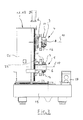
- the FIG. 1 shows in perspective a device 1 for processing a rod-shaped profile blank 2, as this example in the FIG. 2 is indicated.
- the profile blank 2 may include, for example, a plastic hollow profile, an aluminum profile or a wooden profile.
- the profile blank 2 is by means of a transport device 3 - indicated in the FIG. 1 - Moved and braced in the processing device 1 in at least one direction.
- two processing tools 4 and 5 are arranged in a plane perpendicular to the transport direction, which are movable in the X, Y and Z plane.
- the processing tools 4, 5 are each arranged on a movable in the X-plane arm 6 of the processing device 1, at the free end 7 each have a tool motor 8 is arranged.
- the housing 9 of the tool motor 8, in particular to be seen in the FIG. 4 Is at a perpendicular to the arm 6 aligned rotational axis 10 with a plurality of rotary tools 11 and 12 rotatably mounted.
- the rotary tools 11 and 12 may be, for example, a drill or a milling cutter, so that the desired tool 11 or 12 can be used here for machining on the profile blank 2 by the rotation of the housing 9 on the rotational axis 10.
- axis of rotation 13 of the tools 11 and 12 in the housing 9 in the X-plane of the processing device 1 wherein the axis of rotation 13 of the tools 11 and 12 comprises a rotatably mounted in the housing 9 through spindle, here is shown with a dash-dot-like lines.
- the spindle extends from one side of the housing 14 to the other opposite side of the housing 15, so that in each case at the free ends of the spindle in each case a receptacle 16 and 17 for a rotary tool 11 and 12 is arranged.
- the turning tools 11 and 12 as already stated, either a drill and / or a milling cutter.
- the processing device 1, as well as in the FIG. 1 and 2 in this case comprises two processing devices 1.1 and 1.2, each with a processing tool 4 and 5 in a frame 18, wherein between the processing devices 1.1 and 1.2 of the profile blank 2 by means of the transport device 3 in at least one direction is movable and clamped.
- FIG. 1 consists of the individual processing device 1.1 and 1.2 essentially of a arranged in the Y-plane horizontal beam 19, on which a arranged in the Z-plane vertical support 20 is arranged, which is movable in the Y-plane, and wherein the vertical support 20, an arm 6 for the machining tool 4, 5 forming cross member 21 is provided, which is movable in the X-plane.
- the vertical beam 20 and the cross member 21 by means of spindles 22 guided carriage 24 arranged so as to achieve the process of the respective carrier on the other carrier in the respective levels X, Y and Z in this way.
Abstract
Die Erfindung betrifft eine Vorrichtung (1) zur Bearbeitung eines stangenförmigen Profilrohlings (2) wie beispielsweise einem Kunststoffprofil, einem Aluminiumprofil, einem Holzprofilen oder dergleichen, welches mittels einer Transporteinrichtung (3) an einer Bearbeitungseinrichtung (1) in wenigsten einer Richtung bewegbar und verspannbar ist, und wobei wenigstens ein Bearbeitungswerkzeug (4, 5) in einer Ebene senkrecht zur Transportrichtung angeordnet ist, welches in der X-Y-Z-Ebene verfahrbar ist. Gemäß der Erfindung ist das Bearbeitungswerkzeug (4, 5) an einem in der X-Ebene verfahrbaren Arm (6) der Bearbeitungseinrichtung (1) angeordnet, an dessen freien Ende (7) ein Werkzeugmotor (8) angeordnet ist, dessen Gehäuse (9) an einer senkrecht zum Arm (6) ausgerichteten Rotationsachse (10) mit mehreren Drehwerkzeugen (11) und (12) drehbar gelagert ist.The invention relates to a device (1) for processing a rod-shaped profile blank (2) such as a plastic profile, an aluminum profile, a wooden profiles or the like, which by means of a transport device (3) on a processing device (1) in at least one direction movable and braced , and wherein at least one machining tool (4, 5) is arranged in a plane perpendicular to the transport direction, which is movable in the XYZ plane. According to the invention, the machining tool (4, 5) is arranged on a movable in the X-plane arm (6) of the processing device (1), at the free end (7) a tool motor (8) is arranged, the housing (9). on a perpendicular to the arm (6) aligned rotational axis (10) with a plurality of rotary tools (11) and (12) is rotatably mounted.
Description
Die Erfindung betrifft eine Vorrichtung zur Bearbeitung von stangenförmigen Profilrohlingen wie beispielsweise Kunststoffprofile, Aluminiumprofile, Holzprofile oder dergleichen, welche mittels einer Transporteinrichtung an einer Bearbeitungseinrichtung in wenigstens einer Richtung bewegbar und verspannbar sind und wobei wenigstens ein Bearbeitungswerkzeug in einer Ebene senkrecht zur Transportrichtung angeordnet ist, welches in der X-Y-Z-Ebene verfahrbar ist.The invention relates to a device for processing rod-shaped profile blanks such as plastic profiles, aluminum profiles, wood profiles or the like, which are movable and clamped by means of a transport device to a processing device in at least one direction and at least one machining tool is arranged in a plane perpendicular to the transport direction, which can be moved in the XYZ plane.
Bei der Bearbeitung von Profilen, wie sie beispielsweise bei der Herstellung von Türen oder Fenstern verwendet werden, sind zahlreiche unterschiedliche Arbeitsvorgänge durchzuführen. Solche Profile können aus Kunststoff, Metall oder Holz bestehen. Auch eine Kombination verschiedener Materialien ist möglich. Werden z. B. Kunststoffhohlprofile für Fenster bearbeitet, so müssen Entwässerungsschlitze schräg in den Falz und/oder nach unten und/oder nach vorne gefräst werden. Außerdem sind Schließteilpositionsbohrungen an einem Blendrahmenprofil und oder an einem Kämpferprofil zu setzen. Weiterhin müssen ggf. Schlosskästen ausgefräst, Nippelschrauben für Rolllädenführungsleisten und Wetterschenkel verbaut werden. Ferner sind im Flügelüberschlag Eckbandbohrungen vorzusehen. Für Entwässerungs- und Belüftungsschlitze sind andere Werkzeugdurchmesser als für Schließteilbohrungen sowie für Scheren- und Eckbandbohrungen erforderlich. Um diese unterschiedlichen Bohrungen und Ausfräsungen durchführen zu können, sind daher verschiedene Bearbeitungswerkzeuge erforderlich. So sind von vornherein verschiedene Bohrer mit jeweils unterschiedlichen Einsätzen oder unterschiedliche Bohrwerkzeuge vorzusehen. Bei der herkömmlichen Bearbeitung von Profilen werden lange Profilstangen auf einen Tisch oder dergleichen gelegt und mit einer an ihrem hinteren Ende greifenden Vorrichtung zu den Bearbeitungsstationen geschoben bzw. gezogen, die entlang der Verschiebeachse der Profilstange angeordnet sind. Es findet somit eine fließbandmäßige Bearbeitung der Profilstangen statt. So ist es bekannt, dass mittels einer Transporteinrichtung an einer Bearbeitungseinrichtung in wenigstens einer Richtung der Profilrohling bewegbar und verspannbar ist und wobei wenigstens ein Bearbeitungswerkzeug in einer Ebene senkrecht zur Transportrichtung angeordnet ist, welches in der X-Z-Y-Ebene verfahrbar ist.In the processing of profiles, such as those used in the manufacture of doors or windows, numerous different operations must be performed. Such profiles may be made of plastic, metal or wood. A combination of different materials is possible. Are z. B. processed plastic hollow profiles for windows, drainage slots must be obliquely milled into the fold and / or down and / or forward. In addition, closing part position holes are to be placed on a frame profile and or on a fighter profile. Furthermore, if necessary lock housings must be milled out, nipple screws for roller shutter guide rails and weather legs are installed. Furthermore, corner band holes are to be provided in the wing flap. Drainage and ventilation slots require different tool diameters than keyhole, scissor, and corner bore holes. In order to perform these different holes and cutouts, therefore, different editing tools are required. Thus, from the outset, different drills with different inserts or different drilling tools are provided. In the conventional processing Profiles long profile rods are placed on a table or the like and pushed or drawn with a device engaging at its rear end to the processing stations, which are arranged along the displacement axis of the profile bar. It thus takes place a Fließbandmäßig processing of the profile bars. Thus, it is known that by means of a transport device on a processing device in at least one direction of the profile blank is movable and clamped and wherein at least one processing tool is arranged in a plane perpendicular to the transport direction, which is movable in the XZY plane.
So ist beispielsweise aus der
Bei dieser aus dem Stand der Technik bekannten Vorrichtung wird es als nachteilig angesehen, dass die Werkzeuge vornehmlich senkrecht zum Profil in dem Rahmen angeordnet sind, wobei, wenn sie unter einem Winkel angeordnet werden sollen, diese am Rahmen auch entsprechend ausgerichtet werden müssen. Diese Rahmenhalterung für die Werkzeuge hat auch zudem den Nachteil, dass entsprechend viele Motoren mit entsprechenden Werkzeugen an dem Rahmen vorgesehen werden müssen, um auf diese Weise die entsprechenden Durchmesser der Fräsungen oder auch der Bohrungen an dem Profilrohling vornehmen zu können.In this known from the prior art device, it is considered disadvantageous that the tools are arranged primarily perpendicular to the profile in the frame, which, if they are to be arranged at an angle, they must also be aligned on the frame. This frame holder for the tools also has the disadvantage that a corresponding number of motors must be provided with appropriate tools on the frame in order to make in this way the corresponding diameter of the milling or drilling of the profile blank can.
Der Erfindung stellt sich somit das Problem eine Vorrichtung zum Bearbeiten von stangenförmigen Werkstücken derart weiterzubilden, welche hinsichtlich der einzusetzenden Werkzeuge gering ausfällt, wobei insbesondere eine Bearbeitung an dem Profilrohling in unterschiedlichen Winkellagen um das Profil herum vorgenommen werden kann.The invention thus raises the problem of developing a device for processing rod-shaped workpieces, which is low in terms of tools to be used, in particular, a processing on the profile blank in different angular positions around the profile can be made around.
Erfindungsgemäß wird das Problem mit den Merkmalen des Anspruchs 1 gelöst, vorteilhafte Ausgestaltungen der Erfindung ergeben sich aus den Unteransprüchen.According to the invention the problem is solved with the features of claim 1, advantageous embodiments of the invention will become apparent from the dependent claims.
Die mit der Erfindung erreichten Vorteile bestehen nun darin, dass aufgrund eines am Arm der Bearbeitungseinrichtung rotierend gelagerten Gehäuses eines Werkzeugmotors mehrere Bearbeitungswerkzeuge zum Einsatz kommen können, die in jeder Winkellage einen Eingriff am Profilrohling vornehmen können. So sind ein Bohrer und ein Fräser an einem Bearbeitungswerkzeug mit einem Motor vorgesehen, wobei durch Drehen des Gehäuses an der Rotationsachse das entsprechend vorgehaltene Werkzeug, hier ein Bohrer oder ein Fräser, zum Einsatz kommen kann. Soll beispielsweise für Schließbleche eine Bohrung erstellt werden und anschließend ein Entwässerungsschlitz gefräst werden, so kann mit einem Bearbeitungswerkzeug durch Verschwenkung um 180 ° das entsprechende Werkzeug hier abgerufen werden, so dass entweder ein Fräser oder ein Bohrer zum Einsatz kommt, der die entsprechenden Arbeiten am Profilrohling durchführt. Aufgrund der Verfahrbarkeit und der Drehbarkeit des Bearbeitungswerkzeugs an der Bearbeitungseinrichtung in den unterschiedlichen Ebenen wie X, Y und Z, besteht zudem die Möglichkeit das Profil in jeder Lage von oben, von den Seiten und von unten her mit dem entsprechend vorgehaltenen Werkzeug zu bearbeiten. Die Vorzüge der erfindungsgemäßen Ausführung sind daher insbesondere darin zu sehen, dass eine Reduzierung der Bearbeitungsmotoren erreicht wird, was die Herstellungskosten senkt, wobei zudem eine stufenlose winkelbezogene Bearbeitung an dem Profil vorgenommen werden kann.The advantages achieved with the invention consist in the fact that, due to a housing of a tool motor mounted in a rotating manner on the arm of the machining device, a plurality of machining tools can be used which can engage the profile blank in each angular position. Thus, a drill and a milling cutter are provided on a machining tool with a motor, wherein by rotating the housing on the axis of rotation, the correspondingly held tool, here a drill or a milling cutter, can be used. If, for example, a bore is to be created for strike plates and then a drainage slot is milled, the corresponding tool can be retrieved here by pivoting through 180 ° with a machining tool, so that either a milling cutter or a drill is used, which performs the appropriate work on the profile blank performs. Due to the movability and the rotatability of the machining tool on the processing device in the different levels such as X, Y and Z, there is also the possibility to edit the profile in each layer from above, from the sides and from below with the tool accordingly held. The advantages of the embodiment according to the invention are therefore to be seen in particular in that a reduction of the machining motors is achieved, which reduces the production costs, in addition, a stepless angle-related processing can be made on the profile.
Erfindungsgemäß wird das Problem dadurch gelöst, dass das Bearbeitungswerkzeug an einem in der X-Ebene verfahrbaren Arm der Bearbeitungseinrichtung angeordnet ist, an dessen freien Ende ein Werkzeugmotor angeordnet ist, dessen Gehäuse an einer senkrecht zum Arm ausgerichteten Rotationsachse mit mehreren Drehwerkzeugen drehbar gelagert ist. Dabei liegt die Drehachse der Werkzeuge in dem Gehäuse in der X-Ebene der Bearbeitungseinrichtung. Die Drehachse der Werkzeuge umfasst hierbei eine in dem Gehäuse eine drehbar gelagerte durchgehende Spindel.According to the invention, the problem is solved in that the machining tool is arranged on a movable in the X-plane arm of the processing device, at the free end of a tool motor is arranged, the housing is rotatably mounted on a rotational axis aligned perpendicular to the arm with a plurality of rotary tools. In this case, the axis of rotation of the tools in the housing in the X-plane of the processing device. The axis of rotation of the tools in this case comprises a rotatably mounted in the housing through spindle.
Hierbei erstreckt sich nach einer besonders vorteilhaften Ausgestaltung der Erfindung die Spindel von der einen Gehäuseseite bis zur anderen gegenüberliegenden Gehäuseseite. Somit besteht nun die Möglichkeit, dass an den freien Enden der Spindel jeweils eine Aufnahme für ein Bearbeitungswerkzeug vorgesehen werden kann. Die Bearbeitungswerkzeuge können hierbei entweder Bohrer oder Fräser umfassen.In this case, according to a particularly advantageous embodiment of the invention, the spindle extends from one side of the housing to the other side opposite the housing. Thus, there is now the possibility that in each case a receptacle for a machining tool can be provided at the free ends of the spindle. The processing tools may include either drills or cutters.
Nach einer besonders vorteilhaften Ausgestaltung der Bearbeitungseinrichtung sind zwei Bearbeitungseinrichtungen mit je einem Bearbeitungswerkzeug in einem Gestell angeordnet, zwischen denen der Profilrohling mittels der Transporteinrichtung in wenigstens einer Richtung beweg- oder verspannbar ist. Dabei besteht nach einer besonders vorteilhaften Ausgestaltung die einzelne Bearbeitungseinrichtung im Wesentlichen aus einem in der Y-Ebene angeordneten Horizontalträger, auf dem ein in der Z-Ebene angeordneter Vertikalträger angeordnet ist, der in der Y-Ebene verfahrbar ist und wobei an dem Vertikalträger ein den Arm für das Bearbeitungswerkzeug bildender Querträger vorgesehen ist, der in der X-Ebene verfahrbar ist.According to a particularly advantageous embodiment of the processing device, two processing devices each having a processing tool are arranged in a frame, between which the profile blank can be moved or clamped in at least one direction by means of the transport device. In this case, according to a particularly advantageous embodiment, the individual processing device essentially consists of a horizontal carrier arranged in the Y-plane, on which a vertical carrier arranged in the Z-plane is arranged, which can be moved in the Y-plane and wherein on the vertical carrier a Arm for the machining tool forming cross member is provided which is movable in the X-plane.
Dabei sind jeweils an dem Horizontalträger, dem Vertikalträger und dem Querträger mittels Spindeln geführte Schlitten angeordnet zum Verfahren des Trägers in den jeweiligen Ebenen.In this case, each guided on the horizontal support, the vertical support and the cross member by means of spindles slide arranged for moving the carrier in the respective planes.
Ein Ausführungsbeispiel der Erfindung ist in den Zeichnungen rein schematisch dargestellt und wird nachfolgend näher beschrieben. Es zeigt
- Figur 1
- eine perspektivische Darstellung der erfindungsgemäßen Vorrichtung zur Bearbeitung von stangenförmigen Profilrohlingen;
- Figur 2
- eine Frontansicht der Vorrichtung gemäß der
Figur 1 ; Figur 3- eine Seitenansicht der Vorrichtung und
Figur 4- eine Detailansicht des Gehäuses eines Werkzeugmotors in teilweise geschnittener Ansicht.
- FIG. 1
- a perspective view of the device according to the invention for processing rod-shaped profile blanks;
- FIG. 2
- a front view of the device according to the
FIG. 1 ; - FIG. 3
- a side view of the device and
- FIG. 4
- a detailed view of the housing of a tool motor in a partially sectioned view.
Die
Wie insbesondere aus der Zusammenschau der
Wie insbesondere zu erkennen ist, liegt die Drehachse 13 der Werkzeuge 11 und 12 in dem Gehäuse 9 in der X-Ebene der Bearbeitungseinrichtung 1, wobei die Drehachse 13 der Werkzeuge 11 und 12 eine in dem Gehäuse 9 drehbar gelagerte durchgehende Spindel umfasst, die hier mit einer strichpunktartigen Linienführung dargestellt ist.As can be seen in particular, is the axis of
Wie aus der
Die Bearbeitungseinrichtung 1, sowie sie sich in der
Wie insbesondere aus der
- 11
- Vorrichtung/Bearbeitungsvorrichtung 1.1, 1.2Device / processing device 1.1, 1.2
- 22
- Profilrohlingsection blank
- 33
- Transporteinrichtungtransport means
- 44
- Bearbeitungswerkzeugprocessing tool
- 55
- Bearbeitungswerkzeugprocessing tool
- 66
- Armpoor
- 77
- Freien EndeFree end
- 88th
- Werkzeugmotortools engine
- 99
- Gehäuse MotorHousing engine
- 1010
- Rotationsachseaxis of rotation
- 1111
- Drehwerkzeugturning tool
- 1212
- Drehwerkzeugturning tool
- 1313
- Drehachseaxis of rotation
- 1414
- Gehäuseseitecase side
- 1515
- Gehäuseseitecase side
- 1616
- Aufnahmeadmission
- 1717
- Aufnahmeadmission
- 1818
- Gestellframe
- 1919
- HorizontalträgerHorizontal support
- 2020
- Vertikalträgervertical support
- 2121
- Querträgercrossbeam
- 2222
- Spindelnspindles
- 2323
- Schlittencarriage
Claims (9)
dadurch gekennzeichnet,
dass das Bearbeitungswerkzeug (4, 5) an einem in der X-Ebene verfahrbaren Arm (6) der Bearbeitungseinrichtung (1) angeordnet ist, an dessen freien Ende (7) ein Werkzeugmotor (8) angeordnet ist, dessen Gehäuse (9) an einer senkrecht zum Arm (6) ausgerichteten Rotationsachse (10) mit mehreren Drehwerkzeugen (11) und (12) drehbar gelagert ist.Device (1) for processing a bar-shaped profile blank (2) such as a plastic profile, an aluminum profile, a wooden profile or the like, which by means of a transport device (3) on a processing device (1) in at least one direction movable and braced, and wherein at least a processing tool (4, 5) is arranged in a plane perpendicular to the transport direction, which is movable in the XYZ plane,
characterized,
in that the machining tool (4, 5) is arranged on a movable arm (6) of the machining device (1) in the X-plane, at the free end (7) of which a tool motor (8) is arranged, whose housing (9) is arranged on a perpendicular to the arm (6) aligned rotational axis (10) with a plurality of rotary tools (11) and (12) is rotatably mounted.
dadurch gekennzeichnet,
dass die Drehachse (13) der Drehwerkzeuge (11) und (12) in dem Gehäuse (9) in der X-Ebene der Bearbeitungseinrichtung (1) liegt.Device according to claim 1,
characterized,
in that the axis of rotation (13) of the turning tools (11) and (12) lies in the housing (9) in the X-plane of the machining device (1).
dadurch gekennzeichnet,
dass die Drehachse (13) der Drehwerkzeuge (11) und (12) eine in dem Gehäuse (9) drehbar gelagerte durchgehende Spindel umfasst.Device according to claim 2,
characterized,
in that the axis of rotation (13) of the turning tools (11) and (12) comprises a through spindle rotatably mounted in the housing (9).
dadurch gekennzeichnet,
dass sich die Spindel von der einen Gehäuseseite (14) bis zur anderen gegenüberliegenden Gehäuseseite (15) erstreckt.Device according to claim 3,
characterized,
that the spindle extends from one housing side (14) to the other opposite housing side (15).
dadurch gekennzeichnet,
dass an den freien Enden der Spindel jeweils eine Aufnahme (16) und (17) für ein Drehwerkzeug (11, 12) angeordnet ist.Device according to claim 4,
characterized,
that at the free ends of the spindle in each case a receptacle (16) and (17) for a rotary tool (11, 12) is arranged.
dadurch gekennzeichnet,
dass die Drehwerkzeuge (11, 12) Bohrer und/oder Fräser umfassen.Device according to claims 1 to 5,
characterized,
in that the turning tools (11, 12) comprise drills and / or milling cutters.
dadurch gekennzeichnet,
dass zwei Bearbeitungseinrichtungen (1.1) und (1.2) mit je einem Bearbeitungswerkzeug (4, 5) in einem Gestell (18) angeordnet sind, zwischen denen der Profilrohling (2) mittels der Transporteinrichtung (3) in wenigsten einer Richtung bewegbar und verspannbar ist.Device according to claims 1 to 6,
characterized,
in that two processing devices (1.1) and (1.2) each having a processing tool (4, 5) are arranged in a frame (18) between which the profile blank (2) can be moved and clamped in at least one direction by means of the transport device (3).
dadurch gekennzeichnet,
dass die einzelne Bearbeitungseinrichtung (1.1), (1.2) im Wesentlichen aus einem in der Y-Ebene angeordneter Horizontalträger (19) besteht, auf dem ein in der Z-Ebene angeordneter Vertikalträger (20) angeordnet ist, der in der Y-Ebene verfahrbar ist, und wobei an dem Vertikalträger (20) ein den Arm (6) für das Bearbeitungswerkzeug (4, 5) bildender Querträger (21) vorgesehen ist, der in der X-Ebene verfahrbar ist.Device according to claims 1 to 7,
characterized,
in that the individual processing device (1.1), (1.2) essentially consists of a horizontal carrier (19) arranged in the Y-plane, on which a vertical carrier (20) arranged in the Z-plane is arranged, which can be moved in the Y-plane is, and wherein on the vertical support (20) an arm (6) for the machining tool (4, 5) forming the cross member (21) is provided, which is movable in the X-plane.
dadurch gekennzeichnet,
dass jeweils an dem Horizontalträger (19), dem Vertikalträger (20) und dem Querträger (21) mittels Spindeln (22) geführten Schlitten (23) angeordnet sind zum Verfahren des Trägers (20, 21) in den jeweiligen Ebenen.Device according to claim 8,
characterized,
in that respective carriages (23) guided by spindles (22) are arranged on the horizontal support (19), the vertical support (20) and the cross member (21) for moving the support (20, 21) in the respective planes.
Priority Applications (1)
| Application Number | Priority Date | Filing Date | Title |
|---|---|---|---|
| EP20130188735 EP2862671A1 (en) | 2013-10-15 | 2013-10-15 | Device for processing bar-shaped profile blanks |
Applications Claiming Priority (1)
| Application Number | Priority Date | Filing Date | Title |
|---|---|---|---|
| EP20130188735 EP2862671A1 (en) | 2013-10-15 | 2013-10-15 | Device for processing bar-shaped profile blanks |
Publications (1)
| Publication Number | Publication Date |
|---|---|
| EP2862671A1 true EP2862671A1 (en) | 2015-04-22 |
Family
ID=49447352
Family Applications (1)
| Application Number | Title | Priority Date | Filing Date |
|---|---|---|---|
| EP20130188735 Withdrawn EP2862671A1 (en) | 2013-10-15 | 2013-10-15 | Device for processing bar-shaped profile blanks |
Country Status (1)
| Country | Link |
|---|---|
| EP (1) | EP2862671A1 (en) |
Cited By (3)
| Publication number | Priority date | Publication date | Assignee | Title |
|---|---|---|---|---|
| DE202017003923U1 (en) | 2017-07-26 | 2017-09-18 | Mecal S.R.L. | Machining center for metal profiles |
| CN110300648A (en) * | 2016-12-20 | 2019-10-01 | 席尔梅尔机器有限公司 | Equipment for processing the rod-shaped workpiece of such as window profile or gate material |
| US10486243B2 (en) | 2016-07-28 | 2019-11-26 | Mecal S.R.L. | Machining centers for metal profiles |
Citations (4)
| Publication number | Priority date | Publication date | Assignee | Title |
|---|---|---|---|---|
| DE29610414U1 (en) | 1996-06-13 | 1997-03-20 | Bjm Ingenieurbuero Und Maschin | Device for processing profile blanks |
| DE10213778A1 (en) * | 2002-03-22 | 2003-10-02 | Traub Drehmaschinen Gmbh | Machine tool with rotatable multiple tool carrier has tool carrier head axis running transversely to plane passing through transverse motion axis and longitudinal motion axis |
| EP1712337A1 (en) * | 2005-04-15 | 2006-10-18 | Balestrini Renzo S.p.A. | Machining centre with two operating units with part handling means |
| EP1974853A1 (en) * | 2007-03-30 | 2008-10-01 | ME.C.AL. S.p.A. | Apparatus for machining workpieces |
-
2013
- 2013-10-15 EP EP20130188735 patent/EP2862671A1/en not_active Withdrawn
Patent Citations (4)
| Publication number | Priority date | Publication date | Assignee | Title |
|---|---|---|---|---|
| DE29610414U1 (en) | 1996-06-13 | 1997-03-20 | Bjm Ingenieurbuero Und Maschin | Device for processing profile blanks |
| DE10213778A1 (en) * | 2002-03-22 | 2003-10-02 | Traub Drehmaschinen Gmbh | Machine tool with rotatable multiple tool carrier has tool carrier head axis running transversely to plane passing through transverse motion axis and longitudinal motion axis |
| EP1712337A1 (en) * | 2005-04-15 | 2006-10-18 | Balestrini Renzo S.p.A. | Machining centre with two operating units with part handling means |
| EP1974853A1 (en) * | 2007-03-30 | 2008-10-01 | ME.C.AL. S.p.A. | Apparatus for machining workpieces |
Cited By (5)
| Publication number | Priority date | Publication date | Assignee | Title |
|---|---|---|---|---|
| US10486243B2 (en) | 2016-07-28 | 2019-11-26 | Mecal S.R.L. | Machining centers for metal profiles |
| CN110300648A (en) * | 2016-12-20 | 2019-10-01 | 席尔梅尔机器有限公司 | Equipment for processing the rod-shaped workpiece of such as window profile or gate material |
| CN110300648B (en) * | 2016-12-20 | 2021-12-10 | 席尔梅尔机器有限公司 | Device for machining rod-shaped workpieces |
| US11926012B2 (en) | 2016-12-20 | 2024-03-12 | Schirmer Maschinen Gmbh | Device for machining rod-shaped workpieces such as window profiles or door profiles |
| DE202017003923U1 (en) | 2017-07-26 | 2017-09-18 | Mecal S.R.L. | Machining center for metal profiles |
Similar Documents
| Publication | Publication Date | Title |
|---|---|---|
| DE3511498C2 (en) | Device for processing posts or rungs made of plastic or aluminum profile bars for windows or doors | |
| DE3823635C2 (en) | ||
| EP2862671A1 (en) | Device for processing bar-shaped profile blanks | |
| DE3533404A1 (en) | Woodworking machine | |
| DE19725043B4 (en) | Device for processing bar-shaped workpieces | |
| EP3558608B1 (en) | Device for machining rod-shaped workpieces such as window profiles or door profiles | |
| EP0292863A2 (en) | Woodworking machine | |
| EP1986829A1 (en) | Moulder | |
| EP3238876B1 (en) | Device for machining workpieces in rod form such as window profiles or door profiles | |
| DE4035512C1 (en) | ||
| LU101822B1 (en) | Hole saw assembly for a drilling machine and horizontal hole saw for a hole saw assembly | |
| EP3141337B1 (en) | Device for processing rod-shaped workpieces, such as window or door profiles | |
| EP2537628B1 (en) | Machining unit | |
| DE2415006C3 (en) | Process for the production of window frames with glass retaining bead made of wood and device for carrying out the process | |
| EP0292864A1 (en) | Wood-working machine | |
| DE3917146A1 (en) | Arresting device for woodworking machines - is used for mortice and tenon cutting of window frames | |
| EP3271122B1 (en) | Method for machining a workpiece | |
| DE19624138A1 (en) | Joinery machine for processing strand material | |
| DE4401044B4 (en) | planer | |
| DE10208071B4 (en) | Rip fence device for a saw table | |
| DE10302899A1 (en) | Machine tool for making window frame profiles has counter profiles with supports to position workpieces on machine tool | |
| EP0455962A2 (en) | Apparatus for machining joint elements from natural wood, particularly for window frames and window sash elements | |
| DE2161358A1 (en) | Installation on tenoning machines | |
| DE19641171A1 (en) | Apparatus and for machining window profiles used in buildings | |
| EP1857207B1 (en) | Transportable chop saw |
Legal Events
| Date | Code | Title | Description |
|---|---|---|---|
| PUAI | Public reference made under article 153(3) epc to a published international application that has entered the european phase |
Free format text: ORIGINAL CODE: 0009012 |
|
| 17P | Request for examination filed |
Effective date: 20131015 |
|
| AK | Designated contracting states |
Kind code of ref document: A1 Designated state(s): AL AT BE BG CH CY CZ DE DK EE ES FI FR GB GR HR HU IE IS IT LI LT LU LV MC MK MT NL NO PL PT RO RS SE SI SK SM TR |
|
| AX | Request for extension of the european patent |
Extension state: BA ME |
|
| STAA | Information on the status of an ep patent application or granted ep patent |
Free format text: STATUS: THE APPLICATION IS DEEMED TO BE WITHDRAWN |
|
| 18D | Application deemed to be withdrawn |
Effective date: 20151023 |