EP2862671A1 - Dispositif d'usinage de produits profilés - Google Patents
Dispositif d'usinage de produits profilés Download PDFInfo
- Publication number
- EP2862671A1 EP2862671A1 EP20130188735 EP13188735A EP2862671A1 EP 2862671 A1 EP2862671 A1 EP 2862671A1 EP 20130188735 EP20130188735 EP 20130188735 EP 13188735 A EP13188735 A EP 13188735A EP 2862671 A1 EP2862671 A1 EP 2862671A1
- Authority
- EP
- European Patent Office
- Prior art keywords
- plane
- processing
- tool
- profile
- movable
- Prior art date
- Legal status (The legal status is an assumption and is not a legal conclusion. Google has not performed a legal analysis and makes no representation as to the accuracy of the status listed.)
- Withdrawn
Links
Images


Classifications
-
- B—PERFORMING OPERATIONS; TRANSPORTING
- B23—MACHINE TOOLS; METAL-WORKING NOT OTHERWISE PROVIDED FOR
- B23Q—DETAILS, COMPONENTS, OR ACCESSORIES FOR MACHINE TOOLS, e.g. ARRANGEMENTS FOR COPYING OR CONTROLLING; MACHINE TOOLS IN GENERAL CHARACTERISED BY THE CONSTRUCTION OF PARTICULAR DETAILS OR COMPONENTS; COMBINATIONS OR ASSOCIATIONS OF METAL-WORKING MACHINES, NOT DIRECTED TO A PARTICULAR RESULT
- B23Q39/00—Metal-working machines incorporating a plurality of sub-assemblies, each capable of performing a metal-working operation
- B23Q39/02—Metal-working machines incorporating a plurality of sub-assemblies, each capable of performing a metal-working operation the sub-assemblies being capable of being brought to act at a single operating station
- B23Q39/021—Metal-working machines incorporating a plurality of sub-assemblies, each capable of performing a metal-working operation the sub-assemblies being capable of being brought to act at a single operating station with a plurality of toolheads per workholder, whereby the toolhead is a main spindle, a multispindle, a revolver or the like
- B23Q39/025—Metal-working machines incorporating a plurality of sub-assemblies, each capable of performing a metal-working operation the sub-assemblies being capable of being brought to act at a single operating station with a plurality of toolheads per workholder, whereby the toolhead is a main spindle, a multispindle, a revolver or the like with different working directions of toolheads on same workholder
- B23Q39/026—Metal-working machines incorporating a plurality of sub-assemblies, each capable of performing a metal-working operation the sub-assemblies being capable of being brought to act at a single operating station with a plurality of toolheads per workholder, whereby the toolhead is a main spindle, a multispindle, a revolver or the like with different working directions of toolheads on same workholder simultaneous working of toolheads
-
- B—PERFORMING OPERATIONS; TRANSPORTING
- B23—MACHINE TOOLS; METAL-WORKING NOT OTHERWISE PROVIDED FOR
- B23Q—DETAILS, COMPONENTS, OR ACCESSORIES FOR MACHINE TOOLS, e.g. ARRANGEMENTS FOR COPYING OR CONTROLLING; MACHINE TOOLS IN GENERAL CHARACTERISED BY THE CONSTRUCTION OF PARTICULAR DETAILS OR COMPONENTS; COMBINATIONS OR ASSOCIATIONS OF METAL-WORKING MACHINES, NOT DIRECTED TO A PARTICULAR RESULT
- B23Q39/00—Metal-working machines incorporating a plurality of sub-assemblies, each capable of performing a metal-working operation
- B23Q2039/004—Machines with tool turrets
-
- B—PERFORMING OPERATIONS; TRANSPORTING
- B23—MACHINE TOOLS; METAL-WORKING NOT OTHERWISE PROVIDED FOR
- B23Q—DETAILS, COMPONENTS, OR ACCESSORIES FOR MACHINE TOOLS, e.g. ARRANGEMENTS FOR COPYING OR CONTROLLING; MACHINE TOOLS IN GENERAL CHARACTERISED BY THE CONSTRUCTION OF PARTICULAR DETAILS OR COMPONENTS; COMBINATIONS OR ASSOCIATIONS OF METAL-WORKING MACHINES, NOT DIRECTED TO A PARTICULAR RESULT
- B23Q2240/00—Machine tools specially suited for a specific kind of workpiece
- B23Q2240/007—Elongated workpieces
Definitions
- the invention relates to a device for processing rod-shaped profile blanks such as plastic profiles, aluminum profiles, wood profiles or the like, which are movable and clamped by means of a transport device to a processing device in at least one direction and at least one machining tool is arranged in a plane perpendicular to the transport direction, which can be moved in the XYZ plane.
- a device for the processing of profile blanks known in which individual processing tools are arranged on a frame for processing the individual holes or milling.
- the profile blank is in this case guided by the frame by means of the transport device, so that a compact and small design is achieved due to this design of the processing device, since in particular serving for processing individual units from the series arrangement have been converted into a plane arrangement.
- the individual processing tools such as Bohrfräs-, screw, grinding and sawing tools lie in a plane, wherein the blank to be processed is guided through the working plane, so that according to the position of the blank and the assignment of the corresponding tool, the processing can be performed on the blank ,
- the tools are arranged primarily perpendicular to the profile in the frame, which, if they are to be arranged at an angle, they must also be aligned on the frame.
- This frame holder for the tools also has the disadvantage that a corresponding number of motors must be provided with appropriate tools on the frame in order to make in this way the corresponding diameter of the milling or drilling of the profile blank can.
- the invention thus raises the problem of developing a device for processing rod-shaped workpieces, which is low in terms of tools to be used, in particular, a processing on the profile blank in different angular positions around the profile can be made around.
- a housing of a tool motor mounted in a rotating manner on the arm of the machining device a plurality of machining tools can be used which can engage the profile blank in each angular position.
- a drill and a milling cutter are provided on a machining tool with a motor, wherein by rotating the housing on the axis of rotation, the correspondingly held tool, here a drill or a milling cutter, can be used.
- the corresponding tool can be retrieved here by pivoting through 180 ° with a machining tool, so that either a milling cutter or a drill is used, which performs the appropriate work on the profile blank performs. Due to the movability and the rotatability of the machining tool on the processing device in the different levels such as X, Y and Z, there is also the possibility to edit the profile in each layer from above, from the sides and from below with the tool accordingly held.
- the advantages of the embodiment according to the invention are therefore to be seen in particular in that a reduction of the machining motors is achieved, which reduces the production costs, in addition, a stepless angle-related processing can be made on the profile.
- the problem is solved in that the machining tool is arranged on a movable in the X-plane arm of the processing device, at the free end of a tool motor is arranged, the housing is rotatably mounted on a rotational axis aligned perpendicular to the arm with a plurality of rotary tools.
- the axis of rotation of the tools in the housing in the X-plane of the processing device comprises a rotatably mounted in the housing through spindle.
- the spindle extends from one side of the housing to the other side opposite the housing.
- a receptacle for a machining tool can be provided at the free ends of the spindle.
- the processing tools may include either drills or cutters.
- the individual processing device essentially consists of a horizontal carrier arranged in the Y-plane, on which a vertical carrier arranged in the Z-plane is arranged, which can be moved in the Y-plane and wherein on the vertical carrier a Arm for the machining tool forming cross member is provided which is movable in the X-plane.
- each guided on the horizontal support, the vertical support and the cross member by means of spindles slide arranged for moving the carrier in the respective planes.
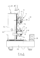
- the FIG. 1 shows in perspective a device 1 for processing a rod-shaped profile blank 2, as this example in the FIG. 2 is indicated.
- the profile blank 2 may include, for example, a plastic hollow profile, an aluminum profile or a wooden profile.
- the profile blank 2 is by means of a transport device 3 - indicated in the FIG. 1 - Moved and braced in the processing device 1 in at least one direction.
- two processing tools 4 and 5 are arranged in a plane perpendicular to the transport direction, which are movable in the X, Y and Z plane.
- the processing tools 4, 5 are each arranged on a movable in the X-plane arm 6 of the processing device 1, at the free end 7 each have a tool motor 8 is arranged.
- the housing 9 of the tool motor 8, in particular to be seen in the FIG. 4 Is at a perpendicular to the arm 6 aligned rotational axis 10 with a plurality of rotary tools 11 and 12 rotatably mounted.
- the rotary tools 11 and 12 may be, for example, a drill or a milling cutter, so that the desired tool 11 or 12 can be used here for machining on the profile blank 2 by the rotation of the housing 9 on the rotational axis 10.
- axis of rotation 13 of the tools 11 and 12 in the housing 9 in the X-plane of the processing device 1 wherein the axis of rotation 13 of the tools 11 and 12 comprises a rotatably mounted in the housing 9 through spindle, here is shown with a dash-dot-like lines.
- the spindle extends from one side of the housing 14 to the other opposite side of the housing 15, so that in each case at the free ends of the spindle in each case a receptacle 16 and 17 for a rotary tool 11 and 12 is arranged.
- the turning tools 11 and 12 as already stated, either a drill and / or a milling cutter.
- the processing device 1, as well as in the FIG. 1 and 2 in this case comprises two processing devices 1.1 and 1.2, each with a processing tool 4 and 5 in a frame 18, wherein between the processing devices 1.1 and 1.2 of the profile blank 2 by means of the transport device 3 in at least one direction is movable and clamped.
- FIG. 1 consists of the individual processing device 1.1 and 1.2 essentially of a arranged in the Y-plane horizontal beam 19, on which a arranged in the Z-plane vertical support 20 is arranged, which is movable in the Y-plane, and wherein the vertical support 20, an arm 6 for the machining tool 4, 5 forming cross member 21 is provided, which is movable in the X-plane.
- the vertical beam 20 and the cross member 21 by means of spindles 22 guided carriage 24 arranged so as to achieve the process of the respective carrier on the other carrier in the respective levels X, Y and Z in this way.
Priority Applications (1)
| Application Number | Priority Date | Filing Date | Title |
|---|---|---|---|
| EP20130188735 EP2862671A1 (fr) | 2013-10-15 | 2013-10-15 | Dispositif d'usinage de produits profilés |
Applications Claiming Priority (1)
| Application Number | Priority Date | Filing Date | Title |
|---|---|---|---|
| EP20130188735 EP2862671A1 (fr) | 2013-10-15 | 2013-10-15 | Dispositif d'usinage de produits profilés |
Publications (1)
| Publication Number | Publication Date |
|---|---|
| EP2862671A1 true EP2862671A1 (fr) | 2015-04-22 |
Family
ID=49447352
Family Applications (1)
| Application Number | Title | Priority Date | Filing Date |
|---|---|---|---|
| EP20130188735 Withdrawn EP2862671A1 (fr) | 2013-10-15 | 2013-10-15 | Dispositif d'usinage de produits profilés |
Country Status (1)
| Country | Link |
|---|---|
| EP (1) | EP2862671A1 (fr) |
Cited By (3)
| Publication number | Priority date | Publication date | Assignee | Title |
|---|---|---|---|---|
| DE202017003923U1 (de) | 2017-07-26 | 2017-09-18 | Mecal S.R.L. | Bearbeitungszentrum für Metallprofile |
| CN110300648A (zh) * | 2016-12-20 | 2019-10-01 | 席尔梅尔机器有限公司 | 用于加工例如窗型材或门型材的棒状工件的设备 |
| US10486243B2 (en) | 2016-07-28 | 2019-11-26 | Mecal S.R.L. | Machining centers for metal profiles |
Citations (4)
| Publication number | Priority date | Publication date | Assignee | Title |
|---|---|---|---|---|
| DE29610414U1 (de) | 1996-06-13 | 1997-03-20 | Bjm Ingenieurbuero Und Maschin | Vorrichtung zur Bearbeitung von Profilrohlingen |
| DE10213778A1 (de) * | 2002-03-22 | 2003-10-02 | Traub Drehmaschinen Gmbh | Werkzeugmaschine |
| EP1712337A1 (fr) * | 2005-04-15 | 2006-10-18 | Balestrini Renzo S.p.A. | Centre d'usinage avec deux unités de travail avec moyens de manipulation de la pièce |
| EP1974853A1 (fr) * | 2007-03-30 | 2008-10-01 | ME.C.AL. S.p.A. | Dspositif pour usiner des pièces |
-
2013
- 2013-10-15 EP EP20130188735 patent/EP2862671A1/fr not_active Withdrawn
Patent Citations (4)
| Publication number | Priority date | Publication date | Assignee | Title |
|---|---|---|---|---|
| DE29610414U1 (de) | 1996-06-13 | 1997-03-20 | Bjm Ingenieurbuero Und Maschin | Vorrichtung zur Bearbeitung von Profilrohlingen |
| DE10213778A1 (de) * | 2002-03-22 | 2003-10-02 | Traub Drehmaschinen Gmbh | Werkzeugmaschine |
| EP1712337A1 (fr) * | 2005-04-15 | 2006-10-18 | Balestrini Renzo S.p.A. | Centre d'usinage avec deux unités de travail avec moyens de manipulation de la pièce |
| EP1974853A1 (fr) * | 2007-03-30 | 2008-10-01 | ME.C.AL. S.p.A. | Dspositif pour usiner des pièces |
Cited By (5)
| Publication number | Priority date | Publication date | Assignee | Title |
|---|---|---|---|---|
| US10486243B2 (en) | 2016-07-28 | 2019-11-26 | Mecal S.R.L. | Machining centers for metal profiles |
| CN110300648A (zh) * | 2016-12-20 | 2019-10-01 | 席尔梅尔机器有限公司 | 用于加工例如窗型材或门型材的棒状工件的设备 |
| CN110300648B (zh) * | 2016-12-20 | 2021-12-10 | 席尔梅尔机器有限公司 | 用于加工棒状的工件的设备 |
| US11926012B2 (en) | 2016-12-20 | 2024-03-12 | Schirmer Maschinen Gmbh | Device for machining rod-shaped workpieces such as window profiles or door profiles |
| DE202017003923U1 (de) | 2017-07-26 | 2017-09-18 | Mecal S.R.L. | Bearbeitungszentrum für Metallprofile |
Similar Documents
| Publication | Publication Date | Title |
|---|---|---|
| DE3511498C2 (de) | Vorrichtung zur Bearbeitung von Pfosten oder Sprossen aus Kunststoff- oder Aluminium-Profilstäben für Fenster oder Türen | |
| DE3823635C2 (fr) | ||
| EP2862671A1 (fr) | Dispositif d'usinage de produits profilés | |
| DE3533404A1 (de) | Holzbearbeitungsmaschine | |
| DE19725043B4 (de) | Vorrichtung zum Bearbeiten von stangenförmigen Werkstücken | |
| EP3558608B1 (fr) | Dispositif d'usinage de pièces en forme de barre, par exemple de profilés de fenêtre ou de profilés de porte | |
| WO2007096163A1 (fr) | Raboteuse | |
| EP3238876B1 (fr) | Dispositif de traitement de pieces usinees en forme de tiges telles que profiles de fenetre ou de porte | |
| EP0292864B1 (fr) | Machine pour travailler le bois | |
| LU101822B1 (de) | Lochsägenanordnung für eine Bohrmaschine und Horizontallochsäge für eine Lochsägenanordnung | |
| EP3141337B1 (fr) | Dispositif de traitement de pieces usinees en forme de tiges par exemple des profils de fenetre ou de porte | |
| EP0813941B2 (fr) | Machine-outil pour l'usinage de pièces allongées | |
| EP2537628B1 (fr) | Machine de traitement | |
| DE2415006C3 (de) | Verfahren zur Herstellung von Fensterrahmen mit Glashalteleiste aus Holz und Vorrichtung zur Durchführung des Verfahrens | |
| DE3917146A1 (de) | Anschlagvorrichtung | |
| EP3271122B1 (fr) | Procede d'usinage d'une piece | |
| DE4401044B4 (de) | Hobelmaschine | |
| DE10208071B4 (de) | Parallelanschlagsvorrichtung für einen Sägetisch | |
| DE10302899A1 (de) | Vorrichtung zur Bearbeitung von stangenförmigen Profilen | |
| EP0455962A2 (fr) | Dispositif pour travailler les zones de jonction en bois naturel, en particulier de cadres pour châssis et dormants de fenêtre | |
| DE2161358A1 (de) | Einrichtung an Zapfenschneidmaschinen | |
| EP1857207B1 (fr) | Scie à onglet transportable | |
| DE2527688A1 (de) | Einsatzwerkzeug fuer handbohrmaschinen | |
| DE2225124A1 (de) | Abricht-, hobel- und fraesmaschine | |
| DE19817610A1 (de) | Montagetisch |
Legal Events
| Date | Code | Title | Description |
|---|---|---|---|
| PUAI | Public reference made under article 153(3) epc to a published international application that has entered the european phase |
Free format text: ORIGINAL CODE: 0009012 |
|
| 17P | Request for examination filed |
Effective date: 20131015 |
|
| AK | Designated contracting states |
Kind code of ref document: A1 Designated state(s): AL AT BE BG CH CY CZ DE DK EE ES FI FR GB GR HR HU IE IS IT LI LT LU LV MC MK MT NL NO PL PT RO RS SE SI SK SM TR |
|
| AX | Request for extension of the european patent |
Extension state: BA ME |
|
| STAA | Information on the status of an ep patent application or granted ep patent |
Free format text: STATUS: THE APPLICATION IS DEEMED TO BE WITHDRAWN |
|
| 18D | Application deemed to be withdrawn |
Effective date: 20151023 |