EP1712337A1 - Machining centre with two operating units with part handling means - Google Patents
Machining centre with two operating units with part handling means Download PDFInfo
- Publication number
- EP1712337A1 EP1712337A1 EP06006074A EP06006074A EP1712337A1 EP 1712337 A1 EP1712337 A1 EP 1712337A1 EP 06006074 A EP06006074 A EP 06006074A EP 06006074 A EP06006074 A EP 06006074A EP 1712337 A1 EP1712337 A1 EP 1712337A1
- Authority
- EP
- European Patent Office
- Prior art keywords
- machining centre
- operating units
- machining
- parts
- previous
- Prior art date
- Legal status (The legal status is an assumption and is not a legal conclusion. Google has not performed a legal analysis and makes no representation as to the accuracy of the status listed.)
- Granted
Links
Images


Classifications
-
- B—PERFORMING OPERATIONS; TRANSPORTING
- B23—MACHINE TOOLS; METAL-WORKING NOT OTHERWISE PROVIDED FOR
- B23Q—DETAILS, COMPONENTS, OR ACCESSORIES FOR MACHINE TOOLS, e.g. ARRANGEMENTS FOR COPYING OR CONTROLLING; MACHINE TOOLS IN GENERAL CHARACTERISED BY THE CONSTRUCTION OF PARTICULAR DETAILS OR COMPONENTS; COMBINATIONS OR ASSOCIATIONS OF METAL-WORKING MACHINES, NOT DIRECTED TO A PARTICULAR RESULT
- B23Q39/00—Metal-working machines incorporating a plurality of sub-assemblies, each capable of performing a metal-working operation
- B23Q39/02—Metal-working machines incorporating a plurality of sub-assemblies, each capable of performing a metal-working operation the sub-assemblies being capable of being brought to act at a single operating station
- B23Q39/021—Metal-working machines incorporating a plurality of sub-assemblies, each capable of performing a metal-working operation the sub-assemblies being capable of being brought to act at a single operating station with a plurality of toolheads per workholder, whereby the toolhead is a main spindle, a multispindle, a revolver or the like
- B23Q39/025—Metal-working machines incorporating a plurality of sub-assemblies, each capable of performing a metal-working operation the sub-assemblies being capable of being brought to act at a single operating station with a plurality of toolheads per workholder, whereby the toolhead is a main spindle, a multispindle, a revolver or the like with different working directions of toolheads on same workholder
- B23Q39/026—Metal-working machines incorporating a plurality of sub-assemblies, each capable of performing a metal-working operation the sub-assemblies being capable of being brought to act at a single operating station with a plurality of toolheads per workholder, whereby the toolhead is a main spindle, a multispindle, a revolver or the like with different working directions of toolheads on same workholder simultaneous working of toolheads
-
- B—PERFORMING OPERATIONS; TRANSPORTING
- B23—MACHINE TOOLS; METAL-WORKING NOT OTHERWISE PROVIDED FOR
- B23Q—DETAILS, COMPONENTS, OR ACCESSORIES FOR MACHINE TOOLS, e.g. ARRANGEMENTS FOR COPYING OR CONTROLLING; MACHINE TOOLS IN GENERAL CHARACTERISED BY THE CONSTRUCTION OF PARTICULAR DETAILS OR COMPONENTS; COMBINATIONS OR ASSOCIATIONS OF METAL-WORKING MACHINES, NOT DIRECTED TO A PARTICULAR RESULT
- B23Q1/00—Members which are comprised in the general build-up of a form of machine, particularly relatively large fixed members
- B23Q1/25—Movable or adjustable work or tool supports
- B23Q1/44—Movable or adjustable work or tool supports using particular mechanisms
- B23Q1/50—Movable or adjustable work or tool supports using particular mechanisms with rotating pairs only, the rotating pairs being the first two elements of the mechanism
- B23Q1/54—Movable or adjustable work or tool supports using particular mechanisms with rotating pairs only, the rotating pairs being the first two elements of the mechanism two rotating pairs only
- B23Q1/5406—Movable or adjustable work or tool supports using particular mechanisms with rotating pairs only, the rotating pairs being the first two elements of the mechanism two rotating pairs only a single rotating pair followed perpendicularly by a single rotating pair
-
- B—PERFORMING OPERATIONS; TRANSPORTING
- B23—MACHINE TOOLS; METAL-WORKING NOT OTHERWISE PROVIDED FOR
- B23Q—DETAILS, COMPONENTS, OR ACCESSORIES FOR MACHINE TOOLS, e.g. ARRANGEMENTS FOR COPYING OR CONTROLLING; MACHINE TOOLS IN GENERAL CHARACTERISED BY THE CONSTRUCTION OF PARTICULAR DETAILS OR COMPONENTS; COMBINATIONS OR ASSOCIATIONS OF METAL-WORKING MACHINES, NOT DIRECTED TO A PARTICULAR RESULT
- B23Q7/00—Arrangements for handling work specially combined with or arranged in, or specially adapted for use in connection with, machine tools, e.g. for conveying, loading, positioning, discharging, sorting
- B23Q7/04—Arrangements for handling work specially combined with or arranged in, or specially adapted for use in connection with, machine tools, e.g. for conveying, loading, positioning, discharging, sorting by means of grippers
- B23Q7/045—Arrangements for handling work specially combined with or arranged in, or specially adapted for use in connection with, machine tools, e.g. for conveying, loading, positioning, discharging, sorting by means of grippers using a tool holder as a work-transporting gripper
-
- B—PERFORMING OPERATIONS; TRANSPORTING
- B27—WORKING OR PRESERVING WOOD OR SIMILAR MATERIAL; NAILING OR STAPLING MACHINES IN GENERAL
- B27C—PLANING, DRILLING, MILLING, TURNING OR UNIVERSAL MACHINES FOR WOOD OR SIMILAR MATERIAL
- B27C9/00—Multi-purpose machines; Universal machines; Equipment therefor
- B27C9/04—Multi-purpose machines; Universal machines; Equipment therefor with a plurality of working spindles
-
- B—PERFORMING OPERATIONS; TRANSPORTING
- B27—WORKING OR PRESERVING WOOD OR SIMILAR MATERIAL; NAILING OR STAPLING MACHINES IN GENERAL
- B27M—WORKING OF WOOD NOT PROVIDED FOR IN SUBCLASSES B27B - B27L; MANUFACTURE OF SPECIFIC WOODEN ARTICLES
- B27M1/00—Working of wood not provided for in subclasses B27B - B27L, e.g. by stretching
- B27M1/08—Working of wood not provided for in subclasses B27B - B27L, e.g. by stretching by multi-step processes
-
- B—PERFORMING OPERATIONS; TRANSPORTING
- B23—MACHINE TOOLS; METAL-WORKING NOT OTHERWISE PROVIDED FOR
- B23Q—DETAILS, COMPONENTS, OR ACCESSORIES FOR MACHINE TOOLS, e.g. ARRANGEMENTS FOR COPYING OR CONTROLLING; MACHINE TOOLS IN GENERAL CHARACTERISED BY THE CONSTRUCTION OF PARTICULAR DETAILS OR COMPONENTS; COMBINATIONS OR ASSOCIATIONS OF METAL-WORKING MACHINES, NOT DIRECTED TO A PARTICULAR RESULT
- B23Q39/00—Metal-working machines incorporating a plurality of sub-assemblies, each capable of performing a metal-working operation
- B23Q2039/004—Machines with tool turrets
-
- B—PERFORMING OPERATIONS; TRANSPORTING
- B23—MACHINE TOOLS; METAL-WORKING NOT OTHERWISE PROVIDED FOR
- B23Q—DETAILS, COMPONENTS, OR ACCESSORIES FOR MACHINE TOOLS, e.g. ARRANGEMENTS FOR COPYING OR CONTROLLING; MACHINE TOOLS IN GENERAL CHARACTERISED BY THE CONSTRUCTION OF PARTICULAR DETAILS OR COMPONENTS; COMBINATIONS OR ASSOCIATIONS OF METAL-WORKING MACHINES, NOT DIRECTED TO A PARTICULAR RESULT
- B23Q2220/00—Machine tool components
- B23Q2220/006—Spindle heads
Definitions
- This invention refers to a machining centre with one or more operating units with part handling units.
- this invention refers to a machining centre, specially fit to perform operations on parts or semi-finished products of chairs and furniture, equipped with one or more operating units, possibly two, including means that suit the picking, the placing and the movement of the parts being machined.
- the known operating centres that are used in this area traditionally include only one operating unit, where the tool is made move along three mutually orthogonal axes, as well as rotationally along at least one plane.
- the equipment described in the above-mentioned patent application envisages both operating units to be located behind the part holding bench, and such architecture makes access to two of the side faces to be machined rather difficult, if not impossible.
- the operating units only have direct access for the rear face, the upper face and the two side faces.
- the part face opposed to the one hosting the operating units, and the lower part face cannot be reached unless suitable overturning devices or gears, which are not aiways accurate and not easily adjustable, are fitted.
- Another inconvenience highlighted by this type of equipment is that, to avoid impediments that hinder the tools from accessing the part to be machined, the part bearing benches are installed on a structure that is separate from the operating units bearing body. This considerably reduces rigidity of the assembly and creates problems in terms of operating accuracy.
- Another problem shown by the mentioned equipment is in connection with the difficulty in configuring the parts bearing benches so as to befit the different morphologies and sizes of the parts.
- the system needs to be fitted with different types of supports and locking devices, which implies a long tooling and equipping time as well as high costs for the tools to be mounted and removed.
- a further problem shown by this equipment is that it provides a difficult access to the parts loading/unloading in manual mode, which is useful during the equipment setting and preparation stage or when lots of reduced size are machined, as the long time required to prepare the automated loading/unloading systems proves to be excessively burdensome.
- the aim of this invention is to remedy the problems reported above.
- the object of this invention is to provide a machining centre, with three or more numerically-controlled axes, which is specially suitable to machine parts of chairs, pieces of furniture, doors and door hardware from woody materials, plastics or light metals, equipped with one or more operating units that can intervene in whatever position on the parts to be machined, with no need to move or handle the parts once they are placed and secured on the work surface.
- a further object of this invention is to provide a machining centre as described above, where all handling, picking and placing of parts, especially as regards their location on the work surface, any movement or capsizing as well as any subsequent unloading when all operations are over, are performed in a simple and easy manner, with no need of bulky equipment that would only hinder the movements of the operating units or would lead to a general increase of dimensions and costs.
- a further object of the invention is to provide a machining centre where the positioning of the benches is executed by the equipment itself through a dedicated positioning programme to be stored within the part machining and positioning programme, so as to reduce the operator's intervention at the machine preparation stage, optimise accuracy of the parts positioning process on the work benches and thus allow for the maximum accuracy of the machining process.
- a further object of the invention is to provide a machining centre that can set up a large number of automated or manual parts loading/unloading, lodging and locking solutions, in consideration of their morphology, type and size.
- a further object of the invention is to provide the users with a machining centre that is such as to ensure a high level of resistance and reliability over time, and which can also be easily and cheaply manufactured.
- the machining centre of this invention which, being specially suitable to carry out operations on parts or semi finished parts of chairs and pieces of furniture arranged over a work bench starting from a magazine, is mainly characterized in that it includes one or more operating units, that are associated with carriages that slide along cross beams operating on rails and located on different levels or misaligned from one another, the said operating units being equipped, next to one end, with an electric chuck with shafts that are connected with machining tools, this chuck being connected in a movable manner to a revolving head.
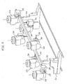
- the machining centre with one or more operating units and with part handling units of this invention preferably with two operating units, whose reference number in the assembly is 10 in figures figure 1 and 1A, includes a bearing frame 12, for instance with a regular parallelepiped or prismatic expansion, formed of a plurality of beams or side members connected to one another in a known manner.
- the bearing frame 12 acts as a support for two pairs of linear slides 28, 28' to which two operating units 18, 20, are connected, respectively, which, in association with carriages or skids 26,26', prove to be sliding on cross members 14, 16, which, in turn, are moved on the mentioned rails 28, 28' located on different levels or misaligned from one another.
- figure 1A depicts the machining centre 10 without the bearing frame 12 and provided with an adjoining magazine 22, per se already known, where the parts to be machined are stored and grouped.
- the linear slides 28, 28' are located orthogonal to one another; it is therefore to be understood that such slides can be oriented otherwise, forming whatever angle shot, or parallel but misaligned from one another.
- Each cross member 14, 16 is equipped with a carriage 26, 26' along which the units 18 and 20 can move orthogonally as to the linear development of the slides themselves.
- these very cross members 14 and 16 are coupled with traditional sliding rails 28 28', along one of the Cartesian axes, as specified hereinafter.
- the sliding of cross members 14 and 16 on slides 28 and 28' is controlled by means of known devices such as precision motors and reducers 29 and 29' which, through special pinions, act on racks 31 and 31', or by means of ball bearing screws.
- the movement of operating units 18 and 20 is likewise controlled by means of motors (not shown either), connected to further similar screws 33 and 33' through belts 35 and 35'.
- the machining centre 10 also includes one or more benches 32 held by frames 32' that support the parts 24 that are from time to time picked from the magazine 22 as indicated below.
- Each of the operating units 18, 20 is equipped at one end with a revolving head 34, which supports a traditional electric chuck 36, which, in turn, rotates in a known way on the front side of head 34 which it is connected to.
- Electric chucks 36 include opposed shafts that are combined in a known way with the tools 38 required to execute the various machining sessions over the parts 24.
- Under the bench/benches 32 or adjoining it a storing and clearing device fro machined parts is located, one of which is referenced with 24' in figure 1A, such as for instance a conveyor belt 40, suited to transfer the parts 24 that have already been machined.
- Electric chucks 36 can move along 5 axes, as schematised in figures 2 and 3 in a detailed view.
- the "X" axis corresponds to the travel of units 18, 20 along the rails 28, 28', the “Y” axis along cross members 14, 16,- and the “Z” axis along similar slides.
- Axes "A” and “C” correspond to the rotation of electric chucks 36 as to the heads 34, and to the rotation of the latter heads as to units 18, 20, respectively.
- the parts 24 can be simultaneously machined in whatever position; once located on benches 32, where they are stabilized with known means, they do not typically demand any further handling, that is they may be treated in whatever position or face owing to the location of the operating units 18 and 20 with the associated electric chucks 36 and tools 38.
- unit 14 located on top can easily access the machining to be executed on the upper, rear and side front faces of part 24; the lower horizontal unit 20, on the contrary, can easily access the upper, lower, rear and side faces.
- Figures 4 and 5 schematically depict the possible operating range of units 18, 20; figure 4 depicts the range of unit 18 or upper vertical unit, whereas figure 5 depicts that of unit 20 or lower horizontal unit.
- the machining centre 10 of this invention includes handling or picking and placing means 24 for the parts to be machined, such means being basically integrated or coupled with at least one of electric mandrels 36, preferably with both electric chucks that have been respectively brought from each operating unit 18 and 20.
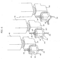
- These handling or picking and handling means 24 and 24' include, in accordance with the preferred embodiment shown in figures 6 and 7, a pneumatic cylinder 42 or equivalent part, whose rod 44 is moved towards the locators 46.
- Both the cylinder 42 and the locators 46 are mounted so as to be moved; therefore, during the machining, the locators 46 are supposed to be withdrawn inside special housings 46' and the cylinder 42 is lowered until it touches the electric mandrel surface 36. These movements are preferably controlled by means of pneumatic or hydraulic cylinders 45 and 47, and allow the dimensions that might reduce the electric chuck operativeness to be removed or reduced in a substantial way.
- the locators 46 and the cylinder 42 are only exposed when a part 24 needs to be picked from the magazine 22 to be placed on work benches 32, or to move, capsize or remove a machined part 24' from the work benches 32 and place it on the stacking and clearing means 40.
- Each part 24 is picked from the magazine 22 by inserting the locators 46, previously exposed through the action of cylinders 45, under the part itself, which is at the bottom of the stack, and hence actuating the cylinder 42 previously raised from the surface of the electric chuck 36 through the action of cylinder 47.
- the rod 44 at this very moment, locates part 24 by compressing it against the locators 46 and temporarily stabilizing it.
- the unit 18 or 20 that bears the electric chuck 36 that caught the part is then duly moved along one or more axes to take the part 24 onto one of the benches 32 and lay it there, provided that the stem 44 of cylinder 42 moves backwards before.
- both the locators 46 and the cylinder 42 are retracted and taken to their hidden position.
- the cylinder 42 and the related locators 36 are preferably fastened above or at one side of both electric chucks 36 taken by the operating units 18 and 20.
- the part is blocked on benches 32, which provide bearings 52 that can be revolved and tilted on the horizontal axis B.
- These benches are advantageously made by faceting the body of small-gauged cylinders which can thus be rotated in special locations.
- These cylinders provide for the part to be pinched on the front and rear sides, so that most of the surfaces to be machined remain free. Their stroke is suited to the gripping of variable-width parts.
- This invention may also include other replacement or additional systems of known type, which are such as to allow parts having extended or more or less bulky shapes to be lodged and blocked.
- the machining centre is equipped with automatic and fast loading/unloading means for parts having extended shapes.
- the benches will be equipped with traditional pneumatic clamping devices with pressing members that operate in a bottom-up or a top-down direction.
- each bench 32 actually includes a blocking device in position 54 which is released by the action of one of the two operating units 18 and 20.
- a special pin 56 is inserted into a special seat provided on the operating unit and the movement of the operating units along the longitudinal slides 28, 28' allows the bench-holding columns 50 to be positioned along special slides 58 in pre-arranged positions of the part machining programme to be executed.
- the driving pin 56 Upon release of the driving pin 56, the column 50 locks in place.
- Each operating unit can thus turn into a part handling robot as well as into an automatic machine setting system.
- the machining centre 10 of this invention allows for operating in whatever position over the whole surface exposed or on all faces of the parts 24, regardless of their section and does not normally demand intermediate handling of the parts, once these have been placed and secured to the bench 32.
- the machining centre of this invention actually allows the part to be translated or capsized while it is being machined.
- This machining centre also features a monolithic structure that properly supports the operating units, the loading/unloading systems and the part resting and clamping benches, with the achievement of rigidity and accuracy values that are typical of numerically-controlled systems.
- a special benefit is derived from the possibility of easily handling the parts 24 without resorting to cumbersome and expensive handling robots, as the means 42, 46 are provided directly on the operating units 18, 20 and, preferably, on the electric chucks 36, too.
- these handling means which can move along the 5 axes provided to move the operating units, will allow a part 24 to be capsized or relocated on the benches even during the work cycle, so as to promote the full machining of all the part faces. In fact, it may be necessary to work on the part resting or clamping areas on the benches and, in such a case, it is indispensable to move or capsize it.
Abstract
Description
- This invention refers to a machining centre with one or more operating units with part handling units.
- More in particular, this invention refers to a machining centre, specially fit to perform operations on parts or semi-finished products of chairs and furniture, equipped with one or more operating units, possibly two, including means that suit the picking, the placing and the movement of the parts being machined.
- As already known, the industrial production of pieces of furniture like chairs, tables, armchairs and the like takes place through the use of special machines, furnished with suitable equipment to mill, drill, shape, dovetail and more, meant to finish parts or match the parts with one another. Such operations include, for instance, milling cogging, drilling and slots created on splines or blocks of wood or any other suitable material and are currently executed by means of traditional-technology machines or by machining centres; these operating centres typically include various tools, which are driven by electronically-operated electric chucks, to be moved along several axes in order to work on the part being machined.
- The known operating centres that are used in this area traditionally include only one operating unit, where the tool is made move along three mutually orthogonal axes, as well as rotationally along at least one plane.
- These movements, which are typically managed and performed by means of a numerical control along 5 axes, allow for space orientation and travels required by the tools in order to execute the above-detailed machining. This known solution inevitably entails the problem of a limited production, this meaning that only one operation at a time can be executed on the part being machined.
- In order to remedy this inconvenience a machining centre has been conceived, already known from
EP 1 250 976 A1 , which includes two operating units placed and made move on the same plane or level through one sole slide. Such a solution is not free from inconveniences, since it does not permit simultaneous intervention on a same part and in adjoining positions with two different tools. In cases when the two units are required to operate in the same position or in positions that are very close to one another, either is preferably and temporarily located outside the other one's operating range. Moreover, if one needs to intervene on all of the faces of parts that are parallelepiped or prismatic in shape, the known work centres needs at least an handling action, an intermediate relocation or turnover of the parts, as the work units cannot move in space to cover all of the six faces. - In work centres with one as well as with two operating units, a further inconvenience is met in connection with the loading/unloading of parts to be machined. Indeed, the latter need to be picked from a loading magazine where they are located in a known manner and repeatedly handled to be submitted to the various machining stages. The parts may even need to be capsized, as when they are being stacked in the magazine it is sometimes necessary to place them in a special position or with a given orientation, whereas at the machining stage a different orientation may be required. All part handling, including unloading when the machining is over, is traditionally carried out by means of automatic systems and means that installed on the machining centre. This traditional solution entails the problem of high system costs, ensuing from the need to prearrange and install such loading/unloading systems which prove to very complicated, too; furthermore, the presence of the latter systems sometimes makes the handling of the operating units more complicated, owing to their dimensions.
- The equipment described in the above-mentioned patent application envisages both operating units to be located behind the part holding bench, and such architecture makes access to two of the side faces to be machined rather difficult, if not impossible. In fact, the operating units only have direct access for the rear face, the upper face and the two side faces. The part face opposed to the one hosting the operating units, and the lower part face cannot be reached unless suitable overturning devices or gears, which are not aiways accurate and not easily adjustable, are fitted. Another inconvenience highlighted by this type of equipment is that, to avoid impediments that hinder the tools from accessing the part to be machined, the part bearing benches are installed on a structure that is separate from the operating units bearing body. This considerably reduces rigidity of the assembly and creates problems in terms of operating accuracy.
- Other problems concern the setting adjustments of the loading/unloading system as well as the bearing and fastening benches of the parts to be machined which, on this equipment, shall be manually performed by properly trained operators. These adjustments require long operating time, and positioning accuracy is extremely subjective, as it depends on the operator's skills. The machining accuracy that can be obtained on the part largely relies on the aforementioned adjustments.
- Another problem shown by the mentioned equipment is in connection with the difficulty in configuring the parts bearing benches so as to befit the different morphologies and sizes of the parts.
- In such a case, the system needs to be fitted with different types of supports and locking devices, which implies a long tooling and equipping time as well as high costs for the tools to be mounted and removed.
- A further problem shown by this equipment is that it provides a difficult access to the parts loading/unloading in manual mode, which is useful during the equipment setting and preparation stage or when lots of reduced size are machined, as the long time required to prepare the automated loading/unloading systems proves to be excessively burdensome.
- The aim of this invention is to remedy the problems reported above.
- More specifically, the object of this invention is to provide a machining centre, with three or more numerically-controlled axes, which is specially suitable to machine parts of chairs, pieces of furniture, doors and door hardware from woody materials, plastics or light metals, equipped with one or more operating units that can intervene in whatever position on the parts to be machined, with no need to move or handle the parts once they are placed and secured on the work surface.
- Its special embodiment allows the operating units to move freely to execute all type of machining, both at the ends or along the part by overlapping their range of action, regardless of the longitudinal positions of either unit compared to the other.
- If two units are required to operate simultaneously in the same positions or in positions that are very close to one another, there is no need to take one of them out of the other one's range of action.
- A further object of this invention is to provide a machining centre as described above, where all handling, picking and placing of parts, especially as regards their location on the work surface, any movement or capsizing as well as any subsequent unloading when all operations are over, are performed in a simple and easy manner, with no need of bulky equipment that would only hinder the movements of the operating units or would lead to a general increase of dimensions and costs.
- A further object of the invention is to provide a machining centre where the positioning of the benches is executed by the equipment itself through a dedicated positioning programme to be stored within the part machining and positioning programme, so as to reduce the operator's intervention at the machine preparation stage, optimise accuracy of the parts positioning process on the work benches and thus allow for the maximum accuracy of the machining process.
- A further object of the invention is to provide a machining centre that can set up a large number of automated or manual parts loading/unloading, lodging and locking solutions, in consideration of their morphology, type and size.
- A further object of the invention is to provide the users with a machining centre that is such as to ensure a high level of resistance and reliability over time, and which can also be easily and cheaply manufactured.
- These and more objects are fulfilled by the machining centre of this invention which, being specially suitable to carry out operations on parts or semi finished parts of chairs and pieces of furniture arranged over a work bench starting from a magazine, is mainly characterized in that it includes one or more operating units, that are associated with carriages that slide along cross beams operating on rails and located on different levels or misaligned from one another, the said operating units being equipped, next to one end, with an electric chuck with shafts that are connected with machining tools, this chuck being connected in a movable manner to a revolving head.
- The constructional and functional features of the machining centre with two operating units and handling units of this invention can be better understood in the following description, where reference is made to the annexed tables of drawings which depict a preferred embodiment, where no limitation of the scope of the invention is intended, and where:
- figures 1 and 1A are schematic representations, in a perspective view, of the machining centre of this invention;
- figure 2 is a schematic representation of the upper vertical operating unit to show the movements of the tool along its five axes;
- figure 3 is a schematic representation of the lower horizontal operating unit to show the movements of the tool along its five axes; figure 4 is a schematic representation of the operating range that can be run by the upper vertical operating unit;
- figure 5 is a schematic representation of the operating range that can be run by the lower horizontal operating unit;
- figure 6 is a schematic representation of the electric chuck installed on the upper vertical unit, to which the machining tools are connected, to show the part gripping and handling means;
- figure 7 is a schematic representation of the electric chuck installed on the lower horizontal unit, to which the machining tools are connected, to show the part gripping and handling means;
- figure 8 is a schematic representation of a column with the part laying and locking bench, to show the related pinching systems.
- With reference to the above-mentioned figures, the machining centre with one or more operating units and with part handling units of this invention, preferably with two operating units, whose reference number in the assembly is 10 in figures figure 1 and 1A, includes a bearing
frame 12, for instance with a regular parallelepiped or prismatic expansion, formed of a plurality of beams or side members connected to one another in a known manner. The bearingframe 12 acts as a support for two pairs oflinear slides 28, 28' to which twooperating units cross members rails 28, 28' located on different levels or misaligned from one another. - For the purposes of promoting a clear understanding of the invention, figure 1A depicts the
machining centre 10 without the bearingframe 12 and provided with anadjoining magazine 22, per se already known, where the parts to be machined are stored and grouped. Advantageously, thelinear slides 28, 28' are located orthogonal to one another; it is therefore to be understood that such slides can be oriented otherwise, forming whatever angle shot, or parallel but misaligned from one another. Eachcross member carriage 26, 26' along which theunits cross members rails 28 28', along one of the Cartesian axes, as specified hereinafter. The sliding ofcross members slides 28 and 28' is controlled by means of known devices such as precision motors andreducers 29 and 29' which, through special pinions, act onracks 31 and 31', or by means of ball bearing screws. - The movement of
slides 26 and 26' is controlled by means of motors (not shown), connected to ball bearingscrews 37 and 37' throughbelts 39 and 39', instead. - The movement of
operating units similar screws 33 and 33' throughbelts 35 and 35'. Themachining centre 10 also includes one ormore benches 32 held by frames 32' that support theparts 24 that are from time to time picked from themagazine 22 as indicated below. - Each of the
operating units head 34, which supports a traditionalelectric chuck 36, which, in turn, rotates in a known way on the front side ofhead 34 which it is connected to.Electric chucks 36 include opposed shafts that are combined in a known way with thetools 38 required to execute the various machining sessions over theparts 24. Under the bench/benches 32 or adjoining it a storing and clearing device fro machined parts is located, one of which is referenced with 24' in figure 1A, such as for instance aconveyor belt 40, suited to transfer theparts 24 that have already been machined. - Electric chucks 36, and hence the tools that are connected to them, can move along 5 axes, as schematised in figures 2 and 3 in a detailed view. The "X" axis corresponds to the travel of
units rails 28, 28', the "Y" axis alongcross members electric chucks 36 as to theheads 34, and to the rotation of the latter heads as tounits - According to this embodiment, which envisages the dislocation of the
units parts 24 can be simultaneously machined in whatever position; once located onbenches 32, where they are stabilized with known means, they do not typically demand any further handling, that is they may be treated in whatever position or face owing to the location of theoperating units electric chucks 36 andtools 38. - In cases when those surfaces that prove to be inaccessible because they rest on the benches or are engaged between the part gripping pincers must be reached, according to the invention it is possible to translate or capsize the part during the machining stage through the systems that will be better described below.
- Considering the machine structure and the arrangement of the work units,
unit 14 located on top can easily access the machining to be executed on the upper, rear and side front faces ofpart 24; the lowerhorizontal unit 20, on the contrary, can easily access the upper, lower, rear and side faces. - Thus, all of the faces of one
single part 24 can be machined, regardless of the positions in which the latter stands and is locked to. In cases when some of the positions or faces of thepart 24 are not easily reached, through robot-driven handling, it is possible to capsize or reposition a part even during the work cycle, as explained below. - Figures 4 and 5 schematically depict the possible operating range of
units unit 18 or upper vertical unit, whereas figure 5 depicts that ofunit 20 or lower horizontal unit. These figures easily show that the operatingunits parts 24, even getting to the point of potentially overlapping one another, moving freely and regardless of the longitudinal positions of one of the units as to the other one, and executing all type of machining both at the ends and along the part itself. - If it is necessary for both units to simultaneously operate in the same positions or in positions that are very close to one another, there is no need to take one out of the other one's operating range.
- Beside this advantageous possibility, the
machining centre 10 of this invention includes handling or picking and placing means 24 for the parts to be machined, such means being basically integrated or coupled with at least one ofelectric mandrels 36, preferably with both electric chucks that have been respectively brought from each operatingunit pneumatic cylinder 42 or equivalent part, whoserod 44 is moved towards thelocators 46. - Both the
cylinder 42 and thelocators 46 are mounted so as to be moved; therefore, during the machining, thelocators 46 are supposed to be withdrawn inside special housings 46' and thecylinder 42 is lowered until it touches theelectric mandrel surface 36. These movements are preferably controlled by means of pneumatic orhydraulic cylinders - The
locators 46 and thecylinder 42 are only exposed when apart 24 needs to be picked from themagazine 22 to be placed onwork benches 32, or to move, capsize or remove a machined part 24' from thework benches 32 and place it on the stacking and clearing means 40. - Each
part 24 is picked from themagazine 22 by inserting thelocators 46, previously exposed through the action ofcylinders 45, under the part itself, which is at the bottom of the stack, and hence actuating thecylinder 42 previously raised from the surface of theelectric chuck 36 through the action ofcylinder 47. Therod 44, at this very moment, locatespart 24 by compressing it against thelocators 46 and temporarily stabilizing it. - The
unit electric chuck 36 that caught the part is then duly moved along one or more axes to take thepart 24 onto one of thebenches 32 and lay it there, provided that thestem 44 ofcylinder 42 moves backwards before. - Once the
part 24 has been located on thework bench 32, both thelocators 46 and thecylinder 42 are retracted and taken to their hidden position. - The
cylinder 42 and therelated locators 36 are preferably fastened above or at one side of bothelectric chucks 36 taken by the operatingunits - The part is blocked on
benches 32, which providebearings 52 that can be revolved and tilted on the horizontal axis B. These benches are advantageously made by faceting the body of small-gauged cylinders which can thus be rotated in special locations. These cylinders provide for the part to be pinched on the front and rear sides, so that most of the surfaces to be machined remain free. Their stroke is suited to the gripping of variable-width parts. - This invention, besides the described loading/unloading systems and benches, may also include other replacement or additional systems of known type, which are such as to allow parts having extended or more or less bulky shapes to be lodged and blocked.
- Furthermore, it also necessary to envisage the possibility that the machining centre is equipped with automatic and fast loading/unloading means for parts having extended shapes.
- In this case, the benches will be equipped with traditional pneumatic clamping devices with pressing members that operate in a bottom-up or a top-down direction.
- To lodge bulky parts, for instance, bearing surfaces are envisaged, fittingly equipped with vacuum-operated clamping systems, and in such a case the loading/unloading will take place in manual mode.
- The several types of
benches 32 so far described finally envisage the possibility for these benches to be mounted on automatically-positioning columns 50, which are moved by the action of the operatingunits - As shown in figure 8, each
bench 32 actually includes a blocking device inposition 54 which is released by the action of one of the two operatingunits special pin 56 is inserted into a special seat provided on the operating unit and the movement of the operating units along thelongitudinal slides 28, 28' allows the bench-holdingcolumns 50 to be positioned alongspecial slides 58 in pre-arranged positions of the part machining programme to be executed. Upon release of the drivingpin 56, thecolumn 50 locks in place. - Each operating unit can thus turn into a part handling robot as well as into an automatic machine setting system.
- As one can discern from the above description, the benefits that ensue from this invention are immediately clear.
- The
machining centre 10 of this invention allows for operating in whatever position over the whole surface exposed or on all faces of theparts 24, regardless of their section and does not normally demand intermediate handling of the parts, once these have been placed and secured to thebench 32. In cases when one wants to reach surfaces that prove to be inaccessible, due to the fact that they are resting on the benches or taken between the part gripping pincers, the machining centre of this invention actually allows the part to be translated or capsized while it is being machined. This machining centre also features a monolithic structure that properly supports the operating units, the loading/unloading systems and the part resting and clamping benches, with the achievement of rigidity and accuracy values that are typical of numerically-controlled systems. Moreover, a special benefit is derived from the possibility of easily handling theparts 24 without resorting to cumbersome and expensive handling robots, as themeans units - Wherever required, these handling means, which can move along the 5 axes provided to move the operating units, will allow a
part 24 to be capsized or relocated on the benches even during the work cycle, so as to promote the full machining of all the part faces. In fact, it may be necessary to work on the part resting or clamping areas on the benches and, in such a case, it is indispensable to move or capsize it. - Although the foregoing disclosure of embodiment of the present invention has been presented for purposes of illustration and description, it is not intended to be exhaustive or to limit the invention to the precise form disclosed, and many variations and modifications of the embodiment described herein will be obvious to one of ordinary skill in the art in the art of the above disclosure. Therefore, this invention is meant to include all modifications and variations that fall within the scope of the invention defined by the claims appended hereto.
Claims (17)
- A machining centre (10) that is specially suited to perform operations on parts or semi finished parts (24) of chairs, pieces of furniture and door hardware from woody materials, plastics or light metals, located on one or more work benches (32) and leaving from a magazine (22), characterized in that it includes one or more operating units (18) and/or (20), combined with carriages (26-26') that slide along cross members (14-16) moving on rails or slides (28-28') and placed on different levels or misaligned from one another, these operating units (18-20) being equipped, at one end, of an electric chuck (36) with shafts to which machining tools (38) are connected, which is movably connected to a revolving head (34).
- The machining centre according to claim 1, characterized in that the cross members (14) and (16) of the operating units (18-20) are position-adjusted and developed orthogonally to one another.
- The machining centre according to claim 1, characterized in that its special conformation allows the operating units (18) and (20) to move freely to carry out all type of machining both at the ends and lengthwise of a part (24) by overlapping their range of action, regardless of the longitudinal positions of cross members (14) and (16) that help supporting and sliding either unit as to the other one, no need to take one of them out of the other one's range of action in cases when these units are required to simultaneously operate in one position or in positions that are very close to one another.
- The machining centre according to claim 1, characterized in that it includes a bearing frame (12) that forms a monolithic structure supporting both the operating units (14) and (16) the benches (32), the latter acting as resting and clamping surfaces for the pieces to be machined.
- The machining centre according to the previous claims, characterized in that it includes, on the operating units (18) and/or (20), gripping and handling means (42-44-46) of the parts (24) located in the magazine (22).
- The machining centre according to any or all of the previous claims, characterized in that these means (42-44) include pneumatic or equivalent-type cylinders and the related rod, and are laterally secured to at least one of the electric chucks (36) fastened to one end of the operating units (18-20).
- The machining centre according to any or all of the previous claims, characterized in that these means (46) include a moving locator that collaborates with the rod (44) of the cylinder/s (42), this moving locating being integral with at least one of the electric chucks (36) of the operating units (18-20).
- The machining centre according to any or all of the previous claims, characterized in that the said locators (46) and the said cyiinderjs (42) are driven by pneumatic or hydraulic pistons (45, 47) that move them to take them to the seats (46') and touch the electric chuck/s (36), respectively.
- The machining centre according to any or all of the previous claims, characterized in that the operating units (18) and/or (20) include means for gripping, releasing and moving the bearing columns of the part bearing benches so that the setting of their positions is automatically adjustable and can be stored in the Numerical Control programme provided for machining the parts
- The machining centre according to any or all of the previous claims, characterized in that the clamping of these pieces occurs through a pinching action, using small-gauged cylinders whose strokes automatically adapt to the size of the parts to be blocked.
- The machining centre according to any or all of the previous claims, characterized in that the clamping systems are the part bearing benches, which are adjustable along the horizontal axis so as to adapt the resting of the parts to any of their possible curved shapes.
- The machining centre according to any or all of the previous claims, characterized in that the operating units (18) and/or (20) include one or more columns (50) that support the benches (32), each of the latter benches being equipped with a position clamping device (54) that collaborates with the mentioned units (18) and/or (20).
- The machining centre according to any or all of the previous claims, characterized in that these benches (32) include at least one pin (56) that is meant to be inserted into a corresponding seat that is found on the operating units (18) and/or (20), as the columns (50) are moved along slides (58) that are fastened to the frame base (12).
- The machining centre according to any or all of the previous claims, characterized in that the parts (24) are clamped on the benches (32) next to bearing levels (52) that can be adjusted along one or more axes.
- The machining centre according to any or all of the previous claims, characterized in that the bench/benches(32) is matched with at least one device (40) for storing and clearing the machined parts (24').
- The machining centre according to any or all of the previous claims, characterized in that at least one device for storing and clearing the machined parts (24') is a conveyor belt.
- The machining centre according to any or all of the previous claims, characterized in that it includes three or more numerically-controlled axes for the machining and/or handling of the parts (24), (24'), as well as for the setting of the machining centre itself.
Applications Claiming Priority (1)
| Application Number | Priority Date | Filing Date | Title |
|---|---|---|---|
| IT000671A ITMI20050671A1 (en) | 2005-04-15 | 2005-04-15 | MACHINING CENTER AT ONE OR MORE UNITS OPERATING WITH PIECE MANIPULATORS |
Publications (2)
| Publication Number | Publication Date |
|---|---|
| EP1712337A1 true EP1712337A1 (en) | 2006-10-18 |
| EP1712337B1 EP1712337B1 (en) | 2008-02-20 |
Family
ID=36677223
Family Applications (1)
| Application Number | Title | Priority Date | Filing Date |
|---|---|---|---|
| EP06006074A Active EP1712337B1 (en) | 2005-04-15 | 2006-03-24 | Machining centre with two operating units with part handling means |
Country Status (5)
| Country | Link |
|---|---|
| EP (1) | EP1712337B1 (en) |
| AT (1) | ATE386625T1 (en) |
| DE (1) | DE602006000545T2 (en) |
| ES (1) | ES2302270T3 (en) |
| IT (1) | ITMI20050671A1 (en) |
Cited By (21)
| Publication number | Priority date | Publication date | Assignee | Title |
|---|---|---|---|---|
| EP1923183A1 (en) | 2006-11-15 | 2008-05-21 | Essetre S.P.A. | Milling machine for machining wood beams |
| EP2017035A1 (en) * | 2007-07-17 | 2009-01-21 | B.G.M. S.r.l. | Overhead handling head for holding tools |
| DE202008012632U1 (en) * | 2008-09-23 | 2010-02-25 | Weeke Bohrsysteme Gmbh | Machining machine for six-sided machining |
| ITPD20080363A1 (en) * | 2008-12-04 | 2010-06-05 | Essetre Holding S R L | MACHINING CENTER PARTICULARLY TYPE TO CARRY OUT MILLING OR CUTTING OF WOOD PANELS |
| ITMO20100042A1 (en) * | 2010-02-25 | 2011-08-26 | Scm Group Spa | OPERATING GROUP FOR A WORKING CENTER |
| ITMI20110036A1 (en) * | 2011-01-18 | 2012-07-19 | Antonio Balestrini | PERFECTED BIROTATIVE HEAD, SPECIES FOR FOUR OR MORE AXIS WORKING CENTERS |
| EP2353820A3 (en) * | 2010-02-10 | 2013-11-13 | Hans Hundegger | Wood processing assembly |
| ITMI20121751A1 (en) * | 2012-10-16 | 2014-04-17 | Pade S R L | WORKING CENTER FOR WOOD PROCESSING |
| EP2862671A1 (en) * | 2013-10-15 | 2015-04-22 | BDM Germany GmbH | Device for processing bar-shaped profile blanks |
| DE102008029074B4 (en) * | 2007-06-12 | 2017-07-06 | Scm Group S.P.A. | machining center |
| DE102017121393A1 (en) | 2016-09-16 | 2018-03-22 | C.M.S. S.P.A. | Machining center with numerical control |
| CN108214707A (en) * | 2018-01-22 | 2018-06-29 | 湖南劳动人事职业学院 | A kind of full-automatic wooden beads milling shape drilling machine |
| DE102017120471A1 (en) * | 2017-09-06 | 2019-03-07 | Hans Hundegger | Board processing plant |
| IT201800001628A1 (en) * | 2018-01-22 | 2019-07-22 | Scm Group Spa | Machine tool and its method of operation. |
| US10384491B2 (en) | 2015-12-10 | 2019-08-20 | Sumitomo Rubber Indusiries, Ltd. | Pneumatic tire |
| WO2019182046A1 (en) * | 2018-03-22 | 2019-09-26 | 国立大学法人千葉大学 | Wood processing system |
| WO2020239152A3 (en) * | 2019-05-27 | 2021-01-21 | Martin Zimmer | Workpiece-processing station comprising a handling-device-controlled multi-processing unit |
| IT202000008404A1 (en) * | 2020-04-20 | 2021-10-20 | Cms Spa | DOUBLE-SIDED MACHINE FOR INDUSTRIAL PROCESSING. |
| CN114535714A (en) * | 2022-04-25 | 2022-05-27 | 深圳市国天电子股份有限公司 | High-precision machining equipment and method for vehicle-mounted millimeter radar cover |
| CN114670037A (en) * | 2022-02-28 | 2022-06-28 | 金雷科技股份公司 | Wind power generation main shaft supporting device |
| CN117324966A (en) * | 2023-12-01 | 2024-01-02 | 常州市蓝托金属制品有限公司 | Multi-hole machining equipment and method for side armrest support of aviation seat |
Families Citing this family (6)
| Publication number | Priority date | Publication date | Assignee | Title |
|---|---|---|---|---|
| CH713011A2 (en) | 2016-10-06 | 2018-04-13 | Kruesi Maschb Ag | Woodworking device. |
| CN107322712A (en) * | 2017-08-16 | 2017-11-07 | 广州市鸿申数控机械有限公司 | A kind of machining center for five-axle linkage tongue-and-groove |
| RU183733U1 (en) * | 2018-04-06 | 2018-10-02 | Чу-Нэн ЮЙ | CNC COMBINED TURNING AND MILLING MACHINE |
| CN110978155A (en) * | 2019-12-24 | 2020-04-10 | 嘉兴智华家居有限公司 | Multi-functional wood processingequipment |
| DE102022122111A1 (en) | 2022-09-01 | 2024-03-07 | Hans Hundegger Beteiligungs Gmbh & Co. Kg | Plate processing plant |
| EP4331770A1 (en) * | 2022-09-01 | 2024-03-06 | elumatec AG | Operating head and method for machining profiled bars |
Citations (4)
| Publication number | Priority date | Publication date | Assignee | Title |
|---|---|---|---|---|
| EP0608746A1 (en) * | 1993-01-19 | 1994-08-03 | BALJER & ZEMBROD GmbH & Co. | Numerically controlled wood-working machine in particular for long workpieces such as beams |
| DE29603804U1 (en) * | 1996-03-01 | 1996-10-02 | Botje Michael | Milling and cutting machine for woodworking |
| DE19518965A1 (en) * | 1995-05-23 | 1996-11-28 | Homag Maschinenbau Ag | Machining centre for wood and plastics |
| EP1250976A1 (en) * | 2001-04-20 | 2002-10-23 | Bacci Paolino Di Bacci Di Agostino | Machine tool for machining elongated pieces |
-
2005
- 2005-04-15 IT IT000671A patent/ITMI20050671A1/en unknown
-
2006
- 2006-03-24 AT AT06006074T patent/ATE386625T1/en not_active IP Right Cessation
- 2006-03-24 DE DE602006000545T patent/DE602006000545T2/en active Active
- 2006-03-24 EP EP06006074A patent/EP1712337B1/en active Active
- 2006-03-24 ES ES06006074T patent/ES2302270T3/en active Active
Patent Citations (4)
| Publication number | Priority date | Publication date | Assignee | Title |
|---|---|---|---|---|
| EP0608746A1 (en) * | 1993-01-19 | 1994-08-03 | BALJER & ZEMBROD GmbH & Co. | Numerically controlled wood-working machine in particular for long workpieces such as beams |
| DE19518965A1 (en) * | 1995-05-23 | 1996-11-28 | Homag Maschinenbau Ag | Machining centre for wood and plastics |
| DE29603804U1 (en) * | 1996-03-01 | 1996-10-02 | Botje Michael | Milling and cutting machine for woodworking |
| EP1250976A1 (en) * | 2001-04-20 | 2002-10-23 | Bacci Paolino Di Bacci Di Agostino | Machine tool for machining elongated pieces |
Cited By (30)
| Publication number | Priority date | Publication date | Assignee | Title |
|---|---|---|---|---|
| EP1923183A1 (en) | 2006-11-15 | 2008-05-21 | Essetre S.P.A. | Milling machine for machining wood beams |
| DE102008029074B4 (en) * | 2007-06-12 | 2017-07-06 | Scm Group S.P.A. | machining center |
| EP2017035A1 (en) * | 2007-07-17 | 2009-01-21 | B.G.M. S.r.l. | Overhead handling head for holding tools |
| DE202008012632U1 (en) * | 2008-09-23 | 2010-02-25 | Weeke Bohrsysteme Gmbh | Machining machine for six-sided machining |
| WO2010034530A1 (en) * | 2008-09-23 | 2010-04-01 | Weeke Bohrsysteme Gmbh | Processing machine for six-sided processing |
| ITPD20080363A1 (en) * | 2008-12-04 | 2010-06-05 | Essetre Holding S R L | MACHINING CENTER PARTICULARLY TYPE TO CARRY OUT MILLING OR CUTTING OF WOOD PANELS |
| EP2353820A3 (en) * | 2010-02-10 | 2013-11-13 | Hans Hundegger | Wood processing assembly |
| EP2894018A1 (en) * | 2010-02-10 | 2015-07-15 | Hans Hundegger | Woodworking machine |
| EP2361738A1 (en) * | 2010-02-25 | 2011-08-31 | SCM Group S.p.A. | Operating unit for a machining centre |
| ITMO20100042A1 (en) * | 2010-02-25 | 2011-08-26 | Scm Group Spa | OPERATING GROUP FOR A WORKING CENTER |
| ITMI20110036A1 (en) * | 2011-01-18 | 2012-07-19 | Antonio Balestrini | PERFECTED BIROTATIVE HEAD, SPECIES FOR FOUR OR MORE AXIS WORKING CENTERS |
| ITMI20121751A1 (en) * | 2012-10-16 | 2014-04-17 | Pade S R L | WORKING CENTER FOR WOOD PROCESSING |
| EP2862671A1 (en) * | 2013-10-15 | 2015-04-22 | BDM Germany GmbH | Device for processing bar-shaped profile blanks |
| US10384491B2 (en) | 2015-12-10 | 2019-08-20 | Sumitomo Rubber Indusiries, Ltd. | Pneumatic tire |
| DE102017121393A1 (en) | 2016-09-16 | 2018-03-22 | C.M.S. S.P.A. | Machining center with numerical control |
| DE102017120471A1 (en) * | 2017-09-06 | 2019-03-07 | Hans Hundegger | Board processing plant |
| CN108214707A (en) * | 2018-01-22 | 2018-06-29 | 湖南劳动人事职业学院 | A kind of full-automatic wooden beads milling shape drilling machine |
| IT201800001628A1 (en) * | 2018-01-22 | 2019-07-22 | Scm Group Spa | Machine tool and its method of operation. |
| EP3513907A1 (en) * | 2018-01-22 | 2019-07-24 | SCM Group S.p.A. | Machine tool and operating method thereof |
| WO2019182046A1 (en) * | 2018-03-22 | 2019-09-26 | 国立大学法人千葉大学 | Wood processing system |
| JP2019166657A (en) * | 2018-03-22 | 2019-10-03 | 国立大学法人千葉大学 | Wood processing system |
| US11648705B2 (en) | 2018-03-22 | 2023-05-16 | National University Corporation Chiba University | Wood processing system |
| CN114450125A (en) * | 2019-05-27 | 2022-05-06 | 马丁·齐默尔 | Workpiece processing station with multiple processing units guided by handling devices |
| WO2020239152A3 (en) * | 2019-05-27 | 2021-01-21 | Martin Zimmer | Workpiece-processing station comprising a handling-device-controlled multi-processing unit |
| EP3900901A1 (en) * | 2020-04-20 | 2021-10-27 | C.M.S. S.p.A. | Double-faced machine for industrial processing |
| IT202000008404A1 (en) * | 2020-04-20 | 2021-10-20 | Cms Spa | DOUBLE-SIDED MACHINE FOR INDUSTRIAL PROCESSING. |
| CN114670037A (en) * | 2022-02-28 | 2022-06-28 | 金雷科技股份公司 | Wind power generation main shaft supporting device |
| CN114535714A (en) * | 2022-04-25 | 2022-05-27 | 深圳市国天电子股份有限公司 | High-precision machining equipment and method for vehicle-mounted millimeter radar cover |
| CN117324966A (en) * | 2023-12-01 | 2024-01-02 | 常州市蓝托金属制品有限公司 | Multi-hole machining equipment and method for side armrest support of aviation seat |
| CN117324966B (en) * | 2023-12-01 | 2024-02-02 | 常州市蓝托金属制品有限公司 | Multi-hole machining equipment and method for side armrest support of aviation seat |
Also Published As
| Publication number | Publication date |
|---|---|
| ITMI20050671A1 (en) | 2006-10-16 |
| EP1712337B1 (en) | 2008-02-20 |
| DE602006000545T2 (en) | 2009-02-19 |
| ATE386625T1 (en) | 2008-03-15 |
| DE602006000545D1 (en) | 2008-04-03 |
| ES2302270T3 (en) | 2008-07-01 |
Similar Documents
| Publication | Publication Date | Title |
|---|---|---|
| EP1712337A1 (en) | Machining centre with two operating units with part handling means | |
| RU2389599C2 (en) | Manipulation system | |
| EP2035199B1 (en) | Machine tool or machining centre with numerically controlled double adjustment of the clamping members | |
| EP2067586A2 (en) | Woodworking machine | |
| US20030099522A1 (en) | Device for mechanically rough machining and/or finish machining cast parts | |
| CN108655494B (en) | Automatic production line for broaching of turbine disc mortises | |
| JPH0716722B2 (en) | Punching machine with replaceable punching tool and work feeding device | |
| US8640313B2 (en) | Machine tool with feed and removal device | |
| EP0455095A1 (en) | Combined machine for processing panels or stacked panels of wood or any like material | |
| EP0364858B1 (en) | Pallet changer | |
| EP3050657B1 (en) | Automated apparatus for processing panels made of wood-like material | |
| KR102309360B1 (en) | Apparatus for unloading workpiece | |
| US20160082559A1 (en) | Machine tool | |
| US20090053000A1 (en) | Compact High Precision Multiple Spindle Computer Controlled Machine Tool | |
| US20090090155A1 (en) | Sheet-Metal Working Machine and Method for Machining Sheets | |
| US5465471A (en) | Apparatus for machining bars | |
| WO2008004263A2 (en) | Machining centre with positioning system of the workpiece clamping members | |
| JP6618544B2 (en) | Multifunctional work stand module | |
| EP1719574A1 (en) | Work centre with a number of numeric control axes for working long pieces, especially in wood | |
| CN110977583A (en) | Automatic processing device for shaft annular positioning groove | |
| EP1247611B1 (en) | A multi-axis work centre, for multiple production, in particular for wood working | |
| WO2016104115A1 (en) | Machine tool | |
| EP1719576B1 (en) | A loading device for a machine tool or work centre and work centre including said loading device | |
| CN112157775A (en) | Positioning system and processing positioning method of woodware processing device | |
| EP1364759A1 (en) | Device to load elongated workpieces to be machined with a machine tool and machine tool comprising said device |
Legal Events
| Date | Code | Title | Description |
|---|---|---|---|
| PUAI | Public reference made under article 153(3) epc to a published international application that has entered the european phase |
Free format text: ORIGINAL CODE: 0009012 |
|
| AK | Designated contracting states |
Kind code of ref document: A1 Designated state(s): AT BE BG CH CY CZ DE DK EE ES FI FR GB GR HU IE IS IT LI LT LU LV MC NL PL PT RO SE SI SK TR |
|
| AX | Request for extension of the european patent |
Extension state: AL BA HR MK YU |
|
| 17P | Request for examination filed |
Effective date: 20070410 |
|
| 17Q | First examination report despatched |
Effective date: 20070511 |
|
| AKX | Designation fees paid |
Designated state(s): AT BE BG CH CY CZ DE DK EE ES FI FR GB GR HU IE IS IT LI LT LU LV MC NL PL PT RO SE SI SK TR |
|
| GRAP | Despatch of communication of intention to grant a patent |
Free format text: ORIGINAL CODE: EPIDOSNIGR1 |
|
| GRAS | Grant fee paid |
Free format text: ORIGINAL CODE: EPIDOSNIGR3 |
|
| GRAA | (expected) grant |
Free format text: ORIGINAL CODE: 0009210 |
|
| AK | Designated contracting states |
Kind code of ref document: B1 Designated state(s): AT BE BG CH CY CZ DE DK EE ES FI FR GB GR HU IE IS IT LI LT LU LV MC NL PL PT RO SE SI SK TR |
|
| REG | Reference to a national code |
Ref country code: GB Ref legal event code: FG4D |
|
| REG | Reference to a national code |
Ref country code: CH Ref legal event code: EP |
|
| REG | Reference to a national code |
Ref country code: IE Ref legal event code: FG4D |
|
| REF | Corresponds to: |
Ref document number: 602006000545 Country of ref document: DE Date of ref document: 20080403 Kind code of ref document: P |
|
| REG | Reference to a national code |
Ref country code: ES Ref legal event code: FG2A Ref document number: 2302270 Country of ref document: ES Kind code of ref document: T3 |
|
| PG25 | Lapsed in a contracting state [announced via postgrant information from national office to epo] |
Ref country code: IS Free format text: LAPSE BECAUSE OF FAILURE TO SUBMIT A TRANSLATION OF THE DESCRIPTION OR TO PAY THE FEE WITHIN THE PRESCRIBED TIME-LIMIT Effective date: 20080620 Ref country code: FI Free format text: LAPSE BECAUSE OF FAILURE TO SUBMIT A TRANSLATION OF THE DESCRIPTION OR TO PAY THE FEE WITHIN THE PRESCRIBED TIME-LIMIT Effective date: 20080220 |
|
| NLV1 | Nl: lapsed or annulled due to failure to fulfill the requirements of art. 29p and 29m of the patents act | ||
| PG25 | Lapsed in a contracting state [announced via postgrant information from national office to epo] |
Ref country code: AT Free format text: LAPSE BECAUSE OF FAILURE TO SUBMIT A TRANSLATION OF THE DESCRIPTION OR TO PAY THE FEE WITHIN THE PRESCRIBED TIME-LIMIT Effective date: 20080220 |
|
| PG25 | Lapsed in a contracting state [announced via postgrant information from national office to epo] |
Ref country code: LV Free format text: LAPSE BECAUSE OF FAILURE TO SUBMIT A TRANSLATION OF THE DESCRIPTION OR TO PAY THE FEE WITHIN THE PRESCRIBED TIME-LIMIT Effective date: 20080220 Ref country code: SI Free format text: LAPSE BECAUSE OF FAILURE TO SUBMIT A TRANSLATION OF THE DESCRIPTION OR TO PAY THE FEE WITHIN THE PRESCRIBED TIME-LIMIT Effective date: 20080220 Ref country code: PL Free format text: LAPSE BECAUSE OF FAILURE TO SUBMIT A TRANSLATION OF THE DESCRIPTION OR TO PAY THE FEE WITHIN THE PRESCRIBED TIME-LIMIT Effective date: 20080220 Ref country code: BE Free format text: LAPSE BECAUSE OF FAILURE TO SUBMIT A TRANSLATION OF THE DESCRIPTION OR TO PAY THE FEE WITHIN THE PRESCRIBED TIME-LIMIT Effective date: 20080220 |
|
| PG25 | Lapsed in a contracting state [announced via postgrant information from national office to epo] |
Ref country code: PT Free format text: LAPSE BECAUSE OF FAILURE TO SUBMIT A TRANSLATION OF THE DESCRIPTION OR TO PAY THE FEE WITHIN THE PRESCRIBED TIME-LIMIT Effective date: 20080721 Ref country code: SE Free format text: LAPSE BECAUSE OF FAILURE TO SUBMIT A TRANSLATION OF THE DESCRIPTION OR TO PAY THE FEE WITHIN THE PRESCRIBED TIME-LIMIT Effective date: 20080520 Ref country code: NL Free format text: LAPSE BECAUSE OF FAILURE TO SUBMIT A TRANSLATION OF THE DESCRIPTION OR TO PAY THE FEE WITHIN THE PRESCRIBED TIME-LIMIT Effective date: 20080220 Ref country code: CZ Free format text: LAPSE BECAUSE OF FAILURE TO SUBMIT A TRANSLATION OF THE DESCRIPTION OR TO PAY THE FEE WITHIN THE PRESCRIBED TIME-LIMIT Effective date: 20080220 Ref country code: SK Free format text: LAPSE BECAUSE OF FAILURE TO SUBMIT A TRANSLATION OF THE DESCRIPTION OR TO PAY THE FEE WITHIN THE PRESCRIBED TIME-LIMIT Effective date: 20080220 Ref country code: MC Free format text: LAPSE BECAUSE OF NON-PAYMENT OF DUE FEES Effective date: 20080331 Ref country code: DK Free format text: LAPSE BECAUSE OF FAILURE TO SUBMIT A TRANSLATION OF THE DESCRIPTION OR TO PAY THE FEE WITHIN THE PRESCRIBED TIME-LIMIT Effective date: 20080220 |
|
| PG25 | Lapsed in a contracting state [announced via postgrant information from national office to epo] |
Ref country code: RO Free format text: LAPSE BECAUSE OF FAILURE TO SUBMIT A TRANSLATION OF THE DESCRIPTION OR TO PAY THE FEE WITHIN THE PRESCRIBED TIME-LIMIT Effective date: 20080220 |
|
| EN | Fr: translation not filed | ||
| PLBE | No opposition filed within time limit |
Free format text: ORIGINAL CODE: 0009261 |
|
| STAA | Information on the status of an ep patent application or granted ep patent |
Free format text: STATUS: NO OPPOSITION FILED WITHIN TIME LIMIT |
|
| 26N | No opposition filed |
Effective date: 20081121 |
|
| PG25 | Lapsed in a contracting state [announced via postgrant information from national office to epo] |
Ref country code: LT Free format text: LAPSE BECAUSE OF FAILURE TO SUBMIT A TRANSLATION OF THE DESCRIPTION OR TO PAY THE FEE WITHIN THE PRESCRIBED TIME-LIMIT Effective date: 20080220 Ref country code: EE Free format text: LAPSE BECAUSE OF FAILURE TO SUBMIT A TRANSLATION OF THE DESCRIPTION OR TO PAY THE FEE WITHIN THE PRESCRIBED TIME-LIMIT Effective date: 20080220 Ref country code: IE Free format text: LAPSE BECAUSE OF NON-PAYMENT OF DUE FEES Effective date: 20080324 |
|
| PG25 | Lapsed in a contracting state [announced via postgrant information from national office to epo] |
Ref country code: FR Free format text: LAPSE BECAUSE OF FAILURE TO SUBMIT A TRANSLATION OF THE DESCRIPTION OR TO PAY THE FEE WITHIN THE PRESCRIBED TIME-LIMIT Effective date: 20081212 Ref country code: BG Free format text: LAPSE BECAUSE OF FAILURE TO SUBMIT A TRANSLATION OF THE DESCRIPTION OR TO PAY THE FEE WITHIN THE PRESCRIBED TIME-LIMIT Effective date: 20080520 |
|
| PG25 | Lapsed in a contracting state [announced via postgrant information from national office to epo] |
Ref country code: CY Free format text: LAPSE BECAUSE OF FAILURE TO SUBMIT A TRANSLATION OF THE DESCRIPTION OR TO PAY THE FEE WITHIN THE PRESCRIBED TIME-LIMIT Effective date: 20080220 |
|
| PG25 | Lapsed in a contracting state [announced via postgrant information from national office to epo] |
Ref country code: IT Free format text: LAPSE BECAUSE OF FAILURE TO SUBMIT A TRANSLATION OF THE DESCRIPTION OR TO PAY THE FEE WITHIN THE PRESCRIBED TIME-LIMIT Effective date: 20080220 |
|
| PG25 | Lapsed in a contracting state [announced via postgrant information from national office to epo] |
Ref country code: LU Free format text: LAPSE BECAUSE OF NON-PAYMENT OF DUE FEES Effective date: 20080324 Ref country code: HU Free format text: LAPSE BECAUSE OF FAILURE TO SUBMIT A TRANSLATION OF THE DESCRIPTION OR TO PAY THE FEE WITHIN THE PRESCRIBED TIME-LIMIT Effective date: 20080821 |
|
| PG25 | Lapsed in a contracting state [announced via postgrant information from national office to epo] |
Ref country code: TR Free format text: LAPSE BECAUSE OF FAILURE TO SUBMIT A TRANSLATION OF THE DESCRIPTION OR TO PAY THE FEE WITHIN THE PRESCRIBED TIME-LIMIT Effective date: 20080220 |
|
| PG25 | Lapsed in a contracting state [announced via postgrant information from national office to epo] |
Ref country code: GR Free format text: LAPSE BECAUSE OF FAILURE TO SUBMIT A TRANSLATION OF THE DESCRIPTION OR TO PAY THE FEE WITHIN THE PRESCRIBED TIME-LIMIT Effective date: 20080521 |
|
| REG | Reference to a national code |
Ref country code: CH Ref legal event code: PL |
|
| GBPC | Gb: european patent ceased through non-payment of renewal fee |
Effective date: 20100324 |
|
| PG25 | Lapsed in a contracting state [announced via postgrant information from national office to epo] |
Ref country code: LI Free format text: LAPSE BECAUSE OF NON-PAYMENT OF DUE FEES Effective date: 20100331 Ref country code: CH Free format text: LAPSE BECAUSE OF NON-PAYMENT OF DUE FEES Effective date: 20100331 |
|
| PG25 | Lapsed in a contracting state [announced via postgrant information from national office to epo] |
Ref country code: GB Free format text: LAPSE BECAUSE OF NON-PAYMENT OF DUE FEES Effective date: 20100324 |
|
| REG | Reference to a national code |
Ref country code: DE Ref legal event code: R082 Ref document number: 602006000545 Country of ref document: DE Representative=s name: KLINGSEISEN & PARTNER, DE Ref country code: DE Ref legal event code: R081 Ref document number: 602006000545 Country of ref document: DE Owner name: C.M.S. S.P.A., IT Free format text: FORMER OWNER: BALESTRINI RENZO S.P.A., SEVESO, MILANO/MAILAND, IT Ref country code: DE Ref legal event code: R081 Ref document number: 602006000545 Country of ref document: DE Owner name: C.M.S. S.P.A., ZOGNO, IT Free format text: FORMER OWNER: BALESTRINI RENZO S.P.A., SEVESO, MILANO/MAILAND, IT Ref country code: DE Ref legal event code: R082 Ref document number: 602006000545 Country of ref document: DE Representative=s name: KLINGSEISEN, RINGS & PARTNER PATENTANWAELTE, DE |
|
| REG | Reference to a national code |
Ref country code: ES Ref legal event code: PC2A Owner name: C.M.S. COSTRUZIONI MACCHINE SPECIALI S.P.A. Effective date: 20151211 |
|
| REG | Reference to a national code |
Ref country code: DE Ref legal event code: R082 Ref document number: 602006000545 Country of ref document: DE Representative=s name: KLINGSEISEN, RINGS & PARTNER PATENTANWAELTE, DE Ref country code: DE Ref legal event code: R081 Ref document number: 602006000545 Country of ref document: DE Owner name: C.M.S. S.P.A., ZOGNO, IT Free format text: FORMER OWNER: C.M.S. S.P.A., SEVESO, IT |
|
| PGFP | Annual fee paid to national office [announced via postgrant information from national office to epo] |
Ref country code: ES Payment date: 20170328 Year of fee payment: 12 |
|
| REG | Reference to a national code |
Ref country code: ES Ref legal event code: FD2A Effective date: 20190911 |
|
| PG25 | Lapsed in a contracting state [announced via postgrant information from national office to epo] |
Ref country code: ES Free format text: LAPSE BECAUSE OF NON-PAYMENT OF DUE FEES Effective date: 20180325 |
|
| PGFP | Annual fee paid to national office [announced via postgrant information from national office to epo] |
Ref country code: DE Payment date: 20230320 Year of fee payment: 18 |
|
| P01 | Opt-out of the competence of the unified patent court (upc) registered |
Effective date: 20230519 |