EP2861422B1 - Toit vitré comportant des moyens d'éclairage et de contrôle de la transmission lumineuse - Google Patents
Toit vitré comportant des moyens d'éclairage et de contrôle de la transmission lumineuse Download PDFInfo
- Publication number
- EP2861422B1 EP2861422B1 EP13731058.7A EP13731058A EP2861422B1 EP 2861422 B1 EP2861422 B1 EP 2861422B1 EP 13731058 A EP13731058 A EP 13731058A EP 2861422 B1 EP2861422 B1 EP 2861422B1
- Authority
- EP
- European Patent Office
- Prior art keywords
- diodes
- layers
- roof
- glass
- sheets
- Prior art date
- Legal status (The legal status is an assumption and is not a legal conclusion. Google has not performed a legal analysis and makes no representation as to the accuracy of the status listed.)
- Active
Links
- 230000005540 biological transmission Effects 0.000 title claims description 63
- 239000010410 layer Substances 0.000 claims description 107
- 239000011521 glass Substances 0.000 claims description 81
- 239000011229 interlayer Substances 0.000 claims description 22
- 230000004907 flux Effects 0.000 claims description 17
- 239000002245 particle Substances 0.000 claims description 8
- 238000004544 sputter deposition Methods 0.000 claims description 6
- BQCADISMDOOEFD-UHFFFAOYSA-N Silver Chemical compound [Ag] BQCADISMDOOEFD-UHFFFAOYSA-N 0.000 claims description 5
- 229910052709 silver Inorganic materials 0.000 claims description 5
- 239000004332 silver Substances 0.000 claims description 5
- 238000001228 spectrum Methods 0.000 claims description 2
- 239000005315 stained glass Substances 0.000 claims 1
- 239000010408 film Substances 0.000 description 37
- 239000000463 material Substances 0.000 description 22
- 238000000034 method Methods 0.000 description 12
- 125000006850 spacer group Chemical group 0.000 description 11
- 238000010521 absorption reaction Methods 0.000 description 9
- 230000008901 benefit Effects 0.000 description 9
- 230000000694 effects Effects 0.000 description 9
- 230000006870 function Effects 0.000 description 8
- 229910052751 metal Inorganic materials 0.000 description 8
- 239000002184 metal Substances 0.000 description 8
- 239000000203 mixture Substances 0.000 description 8
- 230000009467 reduction Effects 0.000 description 8
- 230000002745 absorbent Effects 0.000 description 7
- 239000002250 absorbent Substances 0.000 description 7
- 239000004020 conductor Substances 0.000 description 7
- 238000009826 distribution Methods 0.000 description 7
- 238000005286 illumination Methods 0.000 description 7
- 238000003780 insertion Methods 0.000 description 7
- 230000037431 insertion Effects 0.000 description 7
- 229920000139 polyethylene terephthalate Polymers 0.000 description 7
- 239000005020 polyethylene terephthalate Substances 0.000 description 7
- 238000005452 bending Methods 0.000 description 6
- 238000010438 heat treatment Methods 0.000 description 6
- 230000003287 optical effect Effects 0.000 description 6
- 229920002037 poly(vinyl butyral) polymer Polymers 0.000 description 6
- 230000005855 radiation Effects 0.000 description 6
- 239000000470 constituent Substances 0.000 description 5
- 210000003298 dental enamel Anatomy 0.000 description 5
- 230000010354 integration Effects 0.000 description 5
- 229920000642 polymer Polymers 0.000 description 5
- 230000008859 change Effects 0.000 description 4
- 230000007423 decrease Effects 0.000 description 4
- 238000010586 diagram Methods 0.000 description 4
- 230000005684 electric field Effects 0.000 description 4
- 230000007935 neutral effect Effects 0.000 description 4
- 230000002829 reductive effect Effects 0.000 description 4
- 230000035945 sensitivity Effects 0.000 description 4
- 238000007493 shaping process Methods 0.000 description 4
- 229920001169 thermoplastic Polymers 0.000 description 4
- 239000004416 thermosoftening plastic Substances 0.000 description 4
- 229910001887 tin oxide Inorganic materials 0.000 description 4
- 238000002679 ablation Methods 0.000 description 3
- 230000004075 alteration Effects 0.000 description 3
- 230000015572 biosynthetic process Effects 0.000 description 3
- 229910052500 inorganic mineral Inorganic materials 0.000 description 3
- 230000031700 light absorption Effects 0.000 description 3
- 239000011707 mineral Substances 0.000 description 3
- 238000012986 modification Methods 0.000 description 3
- 230000004048 modification Effects 0.000 description 3
- 238000004806 packaging method and process Methods 0.000 description 3
- 230000035882 stress Effects 0.000 description 3
- 239000000126 substance Substances 0.000 description 3
- XOLBLPGZBRYERU-UHFFFAOYSA-N tin dioxide Chemical compound O=[Sn]=O XOLBLPGZBRYERU-UHFFFAOYSA-N 0.000 description 3
- 238000011282 treatment Methods 0.000 description 3
- LYCAIKOWRPUZTN-UHFFFAOYSA-N Ethylene glycol Chemical compound OCCO LYCAIKOWRPUZTN-UHFFFAOYSA-N 0.000 description 2
- VYPSYNLAJGMNEJ-UHFFFAOYSA-N Silicium dioxide Chemical compound O=[Si]=O VYPSYNLAJGMNEJ-UHFFFAOYSA-N 0.000 description 2
- XUIMIQQOPSSXEZ-UHFFFAOYSA-N Silicon Chemical compound [Si] XUIMIQQOPSSXEZ-UHFFFAOYSA-N 0.000 description 2
- 238000000576 coating method Methods 0.000 description 2
- 239000012141 concentrate Substances 0.000 description 2
- 238000005520 cutting process Methods 0.000 description 2
- 239000003822 epoxy resin Substances 0.000 description 2
- 239000005038 ethylene vinyl acetate Substances 0.000 description 2
- 239000003292 glue Substances 0.000 description 2
- 239000005340 laminated glass Substances 0.000 description 2
- 230000000873 masking effect Effects 0.000 description 2
- 230000003071 parasitic effect Effects 0.000 description 2
- 230000036961 partial effect Effects 0.000 description 2
- 229920003023 plastic Polymers 0.000 description 2
- 239000004033 plastic Substances 0.000 description 2
- 229920001200 poly(ethylene-vinyl acetate) Polymers 0.000 description 2
- 229920000647 polyepoxide Polymers 0.000 description 2
- -1 polyethylene terephthalate Polymers 0.000 description 2
- 230000035807 sensation Effects 0.000 description 2
- 229910052710 silicon Inorganic materials 0.000 description 2
- 239000010703 silicon Substances 0.000 description 2
- 239000012815 thermoplastic material Substances 0.000 description 2
- 239000012780 transparent material Substances 0.000 description 2
- XLYOFNOQVPJJNP-UHFFFAOYSA-N water Substances O XLYOFNOQVPJJNP-UHFFFAOYSA-N 0.000 description 2
- 229910000599 Cr alloy Inorganic materials 0.000 description 1
- PXGOKWXKJXAPGV-UHFFFAOYSA-N Fluorine Chemical compound FF PXGOKWXKJXAPGV-UHFFFAOYSA-N 0.000 description 1
- 229910052581 Si3N4 Inorganic materials 0.000 description 1
- GWEVSGVZZGPLCZ-UHFFFAOYSA-N Titan oxide Chemical compound O=[Ti]=O GWEVSGVZZGPLCZ-UHFFFAOYSA-N 0.000 description 1
- 239000004904 UV filter Substances 0.000 description 1
- QCWXUUIWCKQGHC-UHFFFAOYSA-N Zirconium Chemical compound [Zr] QCWXUUIWCKQGHC-UHFFFAOYSA-N 0.000 description 1
- 229910001093 Zr alloy Inorganic materials 0.000 description 1
- 239000000654 additive Substances 0.000 description 1
- 238000004026 adhesive bonding Methods 0.000 description 1
- 230000032683 aging Effects 0.000 description 1
- 238000013459 approach Methods 0.000 description 1
- 230000000712 assembly Effects 0.000 description 1
- 238000000429 assembly Methods 0.000 description 1
- 230000033228 biological regulation Effects 0.000 description 1
- DQXBYHZEEUGOBF-UHFFFAOYSA-N but-3-enoic acid;ethene Chemical compound C=C.OC(=O)CC=C DQXBYHZEEUGOBF-UHFFFAOYSA-N 0.000 description 1
- 230000015556 catabolic process Effects 0.000 description 1
- 239000000919 ceramic Substances 0.000 description 1
- 238000006243 chemical reaction Methods 0.000 description 1
- 238000007705 chemical test Methods 0.000 description 1
- 229910052804 chromium Inorganic materials 0.000 description 1
- 239000011651 chromium Substances 0.000 description 1
- 239000011248 coating agent Substances 0.000 description 1
- 239000003086 colorant Substances 0.000 description 1
- 238000004040 coloring Methods 0.000 description 1
- 238000004891 communication Methods 0.000 description 1
- 230000000295 complement effect Effects 0.000 description 1
- 150000001875 compounds Chemical class 0.000 description 1
- 238000010276 construction Methods 0.000 description 1
- 238000004132 cross linking Methods 0.000 description 1
- 230000007547 defect Effects 0.000 description 1
- 238000006731 degradation reaction Methods 0.000 description 1
- 238000013461 design Methods 0.000 description 1
- 238000001514 detection method Methods 0.000 description 1
- 230000006866 deterioration Effects 0.000 description 1
- 230000001627 detrimental effect Effects 0.000 description 1
- 238000011161 development Methods 0.000 description 1
- 230000018109 developmental process Effects 0.000 description 1
- 238000009792 diffusion process Methods 0.000 description 1
- 239000006185 dispersion Substances 0.000 description 1
- 230000005672 electromagnetic field Effects 0.000 description 1
- 230000005284 excitation Effects 0.000 description 1
- 238000002474 experimental method Methods 0.000 description 1
- 238000001914 filtration Methods 0.000 description 1
- 239000005357 flat glass Substances 0.000 description 1
- 229920005570 flexible polymer Polymers 0.000 description 1
- 239000012530 fluid Substances 0.000 description 1
- 239000011737 fluorine Substances 0.000 description 1
- 229910052731 fluorine Inorganic materials 0.000 description 1
- 230000004313 glare Effects 0.000 description 1
- 230000017525 heat dissipation Effects 0.000 description 1
- WGCNASOHLSPBMP-UHFFFAOYSA-N hydroxyacetaldehyde Natural products OCC=O WGCNASOHLSPBMP-UHFFFAOYSA-N 0.000 description 1
- RHZWSUVWRRXEJF-UHFFFAOYSA-N indium tin Chemical compound [In].[Sn] RHZWSUVWRRXEJF-UHFFFAOYSA-N 0.000 description 1
- AMGQUBHHOARCQH-UHFFFAOYSA-N indium;oxotin Chemical compound [In].[Sn]=O AMGQUBHHOARCQH-UHFFFAOYSA-N 0.000 description 1
- 150000002500 ions Chemical class 0.000 description 1
- 230000001788 irregular Effects 0.000 description 1
- 230000000670 limiting effect Effects 0.000 description 1
- 238000004519 manufacturing process Methods 0.000 description 1
- 239000011159 matrix material Substances 0.000 description 1
- 238000005259 measurement Methods 0.000 description 1
- 230000007246 mechanism Effects 0.000 description 1
- 229910044991 metal oxide Inorganic materials 0.000 description 1
- 150000004706 metal oxides Chemical class 0.000 description 1
- 238000003032 molecular docking Methods 0.000 description 1
- 230000036651 mood Effects 0.000 description 1
- RVTZCBVAJQQJTK-UHFFFAOYSA-N oxygen(2-);zirconium(4+) Chemical compound [O-2].[O-2].[Zr+4] RVTZCBVAJQQJTK-UHFFFAOYSA-N 0.000 description 1
- 230000002093 peripheral effect Effects 0.000 description 1
- 238000000623 plasma-assisted chemical vapour deposition Methods 0.000 description 1
- 239000002861 polymer material Substances 0.000 description 1
- 238000002360 preparation method Methods 0.000 description 1
- 238000007639 printing Methods 0.000 description 1
- 230000001737 promoting effect Effects 0.000 description 1
- 238000000197 pyrolysis Methods 0.000 description 1
- 238000009877 rendering Methods 0.000 description 1
- 230000004044 response Effects 0.000 description 1
- 230000002441 reversible effect Effects 0.000 description 1
- 239000004065 semiconductor Substances 0.000 description 1
- 238000000926 separation method Methods 0.000 description 1
- 239000000377 silicon dioxide Substances 0.000 description 1
- HQVNEWCFYHHQES-UHFFFAOYSA-N silicon nitride Chemical compound N12[Si]34N5[Si]62N3[Si]51N64 HQVNEWCFYHHQES-UHFFFAOYSA-N 0.000 description 1
- 238000005476 soldering Methods 0.000 description 1
- 239000007787 solid Substances 0.000 description 1
- 239000000758 substrate Substances 0.000 description 1
- 230000000475 sunscreen effect Effects 0.000 description 1
- 239000000516 sunscreening agent Substances 0.000 description 1
- 230000001629 suppression Effects 0.000 description 1
- 239000000725 suspension Substances 0.000 description 1
- 229920002994 synthetic fiber Polymers 0.000 description 1
- 238000007669 thermal treatment Methods 0.000 description 1
- 239000010409 thin film Substances 0.000 description 1
- OGIDPMRJRNCKJF-UHFFFAOYSA-N titanium oxide Inorganic materials [Ti]=O OGIDPMRJRNCKJF-UHFFFAOYSA-N 0.000 description 1
- 239000005341 toughened glass Substances 0.000 description 1
- 238000012546 transfer Methods 0.000 description 1
- 238000002834 transmittance Methods 0.000 description 1
- 230000001960 triggered effect Effects 0.000 description 1
- 238000009827 uniform distribution Methods 0.000 description 1
- 238000003466 welding Methods 0.000 description 1
- 229910001928 zirconium oxide Inorganic materials 0.000 description 1
Images


Classifications
-
- B—PERFORMING OPERATIONS; TRANSPORTING
- B60—VEHICLES IN GENERAL
- B60Q—ARRANGEMENT OF SIGNALLING OR LIGHTING DEVICES, THE MOUNTING OR SUPPORTING THEREOF OR CIRCUITS THEREFOR, FOR VEHICLES IN GENERAL
- B60Q3/00—Arrangement of lighting devices for vehicle interiors; Lighting devices specially adapted for vehicle interiors
- B60Q3/50—Mounting arrangements
- B60Q3/51—Mounting arrangements for mounting lighting devices onto vehicle interior, e.g. onto ceiling or floor
-
- B—PERFORMING OPERATIONS; TRANSPORTING
- B32—LAYERED PRODUCTS
- B32B—LAYERED PRODUCTS, i.e. PRODUCTS BUILT-UP OF STRATA OF FLAT OR NON-FLAT, e.g. CELLULAR OR HONEYCOMB, FORM
- B32B17/00—Layered products essentially comprising sheet glass, or glass, slag, or like fibres
- B32B17/06—Layered products essentially comprising sheet glass, or glass, slag, or like fibres comprising glass as the main or only constituent of a layer, next to another layer of a specific material
- B32B17/10—Layered products essentially comprising sheet glass, or glass, slag, or like fibres comprising glass as the main or only constituent of a layer, next to another layer of a specific material of synthetic resin
- B32B17/10005—Layered products essentially comprising sheet glass, or glass, slag, or like fibres comprising glass as the main or only constituent of a layer, next to another layer of a specific material of synthetic resin laminated safety glass or glazing
- B32B17/10009—Layered products essentially comprising sheet glass, or glass, slag, or like fibres comprising glass as the main or only constituent of a layer, next to another layer of a specific material of synthetic resin laminated safety glass or glazing characterized by the number, the constitution or treatment of glass sheets
- B32B17/10036—Layered products essentially comprising sheet glass, or glass, slag, or like fibres comprising glass as the main or only constituent of a layer, next to another layer of a specific material of synthetic resin laminated safety glass or glazing characterized by the number, the constitution or treatment of glass sheets comprising two outer glass sheets
-
- B—PERFORMING OPERATIONS; TRANSPORTING
- B32—LAYERED PRODUCTS
- B32B—LAYERED PRODUCTS, i.e. PRODUCTS BUILT-UP OF STRATA OF FLAT OR NON-FLAT, e.g. CELLULAR OR HONEYCOMB, FORM
- B32B17/00—Layered products essentially comprising sheet glass, or glass, slag, or like fibres
- B32B17/06—Layered products essentially comprising sheet glass, or glass, slag, or like fibres comprising glass as the main or only constituent of a layer, next to another layer of a specific material
- B32B17/10—Layered products essentially comprising sheet glass, or glass, slag, or like fibres comprising glass as the main or only constituent of a layer, next to another layer of a specific material of synthetic resin
- B32B17/10005—Layered products essentially comprising sheet glass, or glass, slag, or like fibres comprising glass as the main or only constituent of a layer, next to another layer of a specific material of synthetic resin laminated safety glass or glazing
- B32B17/10165—Functional features of the laminated safety glass or glazing
- B32B17/10174—Coatings of a metallic or dielectric material on a constituent layer of glass or polymer
- B32B17/1022—Metallic coatings
- B32B17/10229—Metallic layers sandwiched by dielectric layers
-
- B—PERFORMING OPERATIONS; TRANSPORTING
- B32—LAYERED PRODUCTS
- B32B—LAYERED PRODUCTS, i.e. PRODUCTS BUILT-UP OF STRATA OF FLAT OR NON-FLAT, e.g. CELLULAR OR HONEYCOMB, FORM
- B32B17/00—Layered products essentially comprising sheet glass, or glass, slag, or like fibres
- B32B17/06—Layered products essentially comprising sheet glass, or glass, slag, or like fibres comprising glass as the main or only constituent of a layer, next to another layer of a specific material
- B32B17/10—Layered products essentially comprising sheet glass, or glass, slag, or like fibres comprising glass as the main or only constituent of a layer, next to another layer of a specific material of synthetic resin
- B32B17/10005—Layered products essentially comprising sheet glass, or glass, slag, or like fibres comprising glass as the main or only constituent of a layer, next to another layer of a specific material of synthetic resin laminated safety glass or glazing
- B32B17/10165—Functional features of the laminated safety glass or glazing
- B32B17/10293—Edge features, e.g. inserts or holes
-
- B—PERFORMING OPERATIONS; TRANSPORTING
- B32—LAYERED PRODUCTS
- B32B—LAYERED PRODUCTS, i.e. PRODUCTS BUILT-UP OF STRATA OF FLAT OR NON-FLAT, e.g. CELLULAR OR HONEYCOMB, FORM
- B32B17/00—Layered products essentially comprising sheet glass, or glass, slag, or like fibres
- B32B17/06—Layered products essentially comprising sheet glass, or glass, slag, or like fibres comprising glass as the main or only constituent of a layer, next to another layer of a specific material
- B32B17/10—Layered products essentially comprising sheet glass, or glass, slag, or like fibres comprising glass as the main or only constituent of a layer, next to another layer of a specific material of synthetic resin
- B32B17/10005—Layered products essentially comprising sheet glass, or glass, slag, or like fibres comprising glass as the main or only constituent of a layer, next to another layer of a specific material of synthetic resin laminated safety glass or glazing
- B32B17/10165—Functional features of the laminated safety glass or glazing
- B32B17/10431—Specific parts for the modulation of light incorporated into the laminated safety glass or glazing
- B32B17/10467—Variable transmission
- B32B17/10495—Variable transmission optoelectronic, i.e. optical valve
- B32B17/10532—Suspended particle layer
-
- B—PERFORMING OPERATIONS; TRANSPORTING
- B32—LAYERED PRODUCTS
- B32B—LAYERED PRODUCTS, i.e. PRODUCTS BUILT-UP OF STRATA OF FLAT OR NON-FLAT, e.g. CELLULAR OR HONEYCOMB, FORM
- B32B17/00—Layered products essentially comprising sheet glass, or glass, slag, or like fibres
- B32B17/06—Layered products essentially comprising sheet glass, or glass, slag, or like fibres comprising glass as the main or only constituent of a layer, next to another layer of a specific material
- B32B17/10—Layered products essentially comprising sheet glass, or glass, slag, or like fibres comprising glass as the main or only constituent of a layer, next to another layer of a specific material of synthetic resin
- B32B17/10005—Layered products essentially comprising sheet glass, or glass, slag, or like fibres comprising glass as the main or only constituent of a layer, next to another layer of a specific material of synthetic resin laminated safety glass or glazing
- B32B17/10165—Functional features of the laminated safety glass or glazing
- B32B17/10541—Functional features of the laminated safety glass or glazing comprising a light source or a light guide
-
- B—PERFORMING OPERATIONS; TRANSPORTING
- B32—LAYERED PRODUCTS
- B32B—LAYERED PRODUCTS, i.e. PRODUCTS BUILT-UP OF STRATA OF FLAT OR NON-FLAT, e.g. CELLULAR OR HONEYCOMB, FORM
- B32B17/00—Layered products essentially comprising sheet glass, or glass, slag, or like fibres
- B32B17/06—Layered products essentially comprising sheet glass, or glass, slag, or like fibres comprising glass as the main or only constituent of a layer, next to another layer of a specific material
- B32B17/10—Layered products essentially comprising sheet glass, or glass, slag, or like fibres comprising glass as the main or only constituent of a layer, next to another layer of a specific material of synthetic resin
- B32B17/10005—Layered products essentially comprising sheet glass, or glass, slag, or like fibres comprising glass as the main or only constituent of a layer, next to another layer of a specific material of synthetic resin laminated safety glass or glazing
- B32B17/1055—Layered products essentially comprising sheet glass, or glass, slag, or like fibres comprising glass as the main or only constituent of a layer, next to another layer of a specific material of synthetic resin laminated safety glass or glazing characterized by the resin layer, i.e. interlayer
- B32B17/10761—Layered products essentially comprising sheet glass, or glass, slag, or like fibres comprising glass as the main or only constituent of a layer, next to another layer of a specific material of synthetic resin laminated safety glass or glazing characterized by the resin layer, i.e. interlayer containing vinyl acetal
-
- B—PERFORMING OPERATIONS; TRANSPORTING
- B60—VEHICLES IN GENERAL
- B60Q—ARRANGEMENT OF SIGNALLING OR LIGHTING DEVICES, THE MOUNTING OR SUPPORTING THEREOF OR CIRCUITS THEREFOR, FOR VEHICLES IN GENERAL
- B60Q3/00—Arrangement of lighting devices for vehicle interiors; Lighting devices specially adapted for vehicle interiors
- B60Q3/20—Arrangement of lighting devices for vehicle interiors; Lighting devices specially adapted for vehicle interiors for lighting specific fittings of passenger or driving compartments; mounted on specific fittings of passenger or driving compartments
- B60Q3/208—Sun roofs; Windows
-
- B—PERFORMING OPERATIONS; TRANSPORTING
- B60—VEHICLES IN GENERAL
- B60Q—ARRANGEMENT OF SIGNALLING OR LIGHTING DEVICES, THE MOUNTING OR SUPPORTING THEREOF OR CIRCUITS THEREFOR, FOR VEHICLES IN GENERAL
- B60Q3/00—Arrangement of lighting devices for vehicle interiors; Lighting devices specially adapted for vehicle interiors
- B60Q3/70—Arrangement of lighting devices for vehicle interiors; Lighting devices specially adapted for vehicle interiors characterised by the purpose
- B60Q3/74—Arrangement of lighting devices for vehicle interiors; Lighting devices specially adapted for vehicle interiors characterised by the purpose for overall compartment lighting; for overall compartment lighting in combination with specific lighting, e.g. room lamps with reading lamps
- B60Q3/745—Arrangement of lighting devices for vehicle interiors; Lighting devices specially adapted for vehicle interiors characterised by the purpose for overall compartment lighting; for overall compartment lighting in combination with specific lighting, e.g. room lamps with reading lamps using lighting panels or mats, e.g. electro-luminescent panels, LED mats
-
- B—PERFORMING OPERATIONS; TRANSPORTING
- B60—VEHICLES IN GENERAL
- B60Q—ARRANGEMENT OF SIGNALLING OR LIGHTING DEVICES, THE MOUNTING OR SUPPORTING THEREOF OR CIRCUITS THEREFOR, FOR VEHICLES IN GENERAL
- B60Q3/00—Arrangement of lighting devices for vehicle interiors; Lighting devices specially adapted for vehicle interiors
- B60Q3/70—Arrangement of lighting devices for vehicle interiors; Lighting devices specially adapted for vehicle interiors characterised by the purpose
- B60Q3/76—Arrangement of lighting devices for vehicle interiors; Lighting devices specially adapted for vehicle interiors characterised by the purpose for spotlighting, e.g. reading lamps
-
- F—MECHANICAL ENGINEERING; LIGHTING; HEATING; WEAPONS; BLASTING
- F21—LIGHTING
- F21V—FUNCTIONAL FEATURES OR DETAILS OF LIGHTING DEVICES OR SYSTEMS THEREOF; STRUCTURAL COMBINATIONS OF LIGHTING DEVICES WITH OTHER ARTICLES, NOT OTHERWISE PROVIDED FOR
- F21V14/00—Controlling the distribution of the light emitted by adjustment of elements
- F21V14/003—Controlling the distribution of the light emitted by adjustment of elements by interposition of elements with electrically controlled variable light transmissivity, e.g. liquid crystal elements or electrochromic devices
-
- F—MECHANICAL ENGINEERING; LIGHTING; HEATING; WEAPONS; BLASTING
- F21—LIGHTING
- F21V—FUNCTIONAL FEATURES OR DETAILS OF LIGHTING DEVICES OR SYSTEMS THEREOF; STRUCTURAL COMBINATIONS OF LIGHTING DEVICES WITH OTHER ARTICLES, NOT OTHERWISE PROVIDED FOR
- F21V9/00—Elements for modifying spectral properties, polarisation or intensity of the light emitted, e.g. filters
- F21V9/04—Elements for modifying spectral properties, polarisation or intensity of the light emitted, e.g. filters for filtering out infrared radiation
-
- B—PERFORMING OPERATIONS; TRANSPORTING
- B32—LAYERED PRODUCTS
- B32B—LAYERED PRODUCTS, i.e. PRODUCTS BUILT-UP OF STRATA OF FLAT OR NON-FLAT, e.g. CELLULAR OR HONEYCOMB, FORM
- B32B2605/00—Vehicles
- B32B2605/08—Cars
-
- F—MECHANICAL ENGINEERING; LIGHTING; HEATING; WEAPONS; BLASTING
- F21—LIGHTING
- F21Y—INDEXING SCHEME ASSOCIATED WITH SUBCLASSES F21K, F21L, F21S and F21V, RELATING TO THE FORM OR THE KIND OF THE LIGHT SOURCES OR OF THE COLOUR OF THE LIGHT EMITTED
- F21Y2115/00—Light-generating elements of semiconductor light sources
- F21Y2115/10—Light-emitting diodes [LED]
Definitions
- the invention relates to roofs of vehicles consisting at least partly of a glazing unit. More specifically, the invention relates to roofs whose glazing covers a large part of their surface, or even all of it.
- Glazed roofs are replacing an increasing part of the traditional roofs that are part of the body of vehicles.
- the choice of these roofs is the fact of the manufacturers to offer their customers this option giving the impression of opening the vehicle to the outside, like a cabriolet, without having the disadvantages of the latter, the roofs now the comfort of a traditional sedan.
- glazed roofs must meet many requirements. First of all, it is necessary to meet the safety requirements. Glazed roofs must comply with regulations that require eviction resistance in the event of an accident. In this sense they must satisfy the rules designated "R43". Resistance to the eviction of passengers requires in particular the use of laminated glazing.
- laminated glazing does not exclude the need to limit weight. For this reason the laminated roofs used must also have well-controlled thicknesses. In practice the glazing of these roofs have a thickness which is not greater than 8 mm and preferably not greater than 7.5 mm.
- glazed roofs aims to gain brightness in the cabin. This gain should not be contrary to other properties that ensure passenger comfort, especially thermal comfort.
- the desire for an increase in brightness in the passenger compartment is not necessarily permanent.
- the user can, depending on the time of use, prefer a lower brightness, or simply maintain the "private" character that isolates the cabin from outside looks.
- glazings comprising electro-chromium means in which the variation is obtained by changing the state of colored ions in compositions included in these glazings. It is also glazing comprising layers of particles in suspension, which according to the application of an electrical voltage are ordered or not such as so-called SPD systems (for "suspended particle devices").
- SPD systems for "suspended particle devices"
- the lighting of the cabin is the ambient lighting or the more localized one corresponding to what is called "reading lights".
- the means used for these lights are arranged on the roof or on the inner lining thereof.
- the lighting means are part of an assembly that extends in part on the windshield and which comprises the base of the rearview mirror, various sensors controlling the triggering of the wipers, that of the external floodlights, together which is also the support of means of data communication by way of waves of various frequencies (electronic tolls, GPS ...), or that of assistance to the driving like the infrared cameras.
- the sets in question are a local obstacle to the desired transparency that motivates the choice of these "glass” solutions.
- the invention proposes to make the best use of the glazing constituting the roofs by integrating the lighting means of the passenger compartment so that they do not significantly alter their transparency. This integration, as described later, makes it possible to benefit from new arrangements adapted to these glazed roofs.
- the mode chosen according to the invention is the use of light-emitting diodes (LEDs).
- LEDs light-emitting diodes
- This choice has been proposed previously for example in the applications WO2004 / 062908 , EP1437215 , EP1979160 .
- the diodes are included in the plastic interlayer of the laminated glazing which associates the two sheets of glass.
- the LEDs are powered by either thin conductors ( EP1979160 ) by transparent conductive layers ( EP1437215 ).
- a requirement related to the mode of use concerned, is to have sufficient power, especially for the constitution of lighting type reading.
- the light transmission of glazed roofs is systematically limited, on the one hand to keep a character described as "private", and on the other hand to limit the energy input which is inseparable from the wavelengths of the visible range. For these two reasons at least the light transmission of glazed roofs is normally less than 50% and often much lower, for example of the order of 15 to 20% or less of the incident light.
- the transmission in question can be adjusted in various ways as indicated hereinafter, in particular by the use of sheets which absorb a part of the incident light, but also by means which make it possible to control transmission variations.
- the luminous power for a given illumination it is necessary to take into account the elements which reduce the light emitted by the diodes, and in particular the fact that a more or less important part according to the glazing considered, is absorbed in the passage of the glass sheets, spacers and any element disposed on the path followed by the luminous flux emitted.
- the luminous power required for illumination according to the invention is advantageously distributed over a plurality of diodes.
- the multiplicity of diodes has several advantages.
- a first advantage is, for example, to require the use of diodes of lesser individual power. Even if the power of commercially available diodes has increased considerably, those of moderate power remain advantageous, if only because they remain less expensive. They are also advantageous insofar as the luminous efficiency of the most powerful diodes is not the best. It is therefore preferable to choose diodes that remain in power fields corresponding to the best efficiency. This approach also responds to the need, which is discussed below, to limit the negative consequences that attach to the thermal conditions of implementation of the diodes.
- the energy efficiency of the diodes has also improved significantly over time. For a given power, the heat released tends to decrease in recent products. It remains that the best energy yields - that is to say the share of electrical power converted to light - do not generally exceed 30%, and most commonly remain in the range of 15 to 20%. The heat release Joule effect is important.
- the position of the diodes in the laminate does not facilitate the removal of operating heat.
- the operation of a diode can lead to a local heating such that it ultimately leads to an alteration of the diode itself, soldering to the supply circuit, or elements present in the laminated roof in contact or in the immediate vicinity of the diode.
- glass sheets can withstand a temperature rise without damage, other constituents, including the thermoplastic sheets that join the laminate, need to keep the temperature within relatively small limits. strict, usually below 100 ° C and often below 80 ° C. For this reason it is preferable according to the invention to distribute the total power required on several diodes, each offering only a fraction of this total power, these diodes remaining distant from each other.
- the experiment makes it possible to determine the evolution of the temperature of a given power diode in an environment such as that corresponding to a laminated glazed roof. This determination takes into account that the heat dissipation for a diode is essentially conductive by the materials in contact with which the diode is located. Thermoplastic interlayer materials of the PVB type are not good conductors, mineral or organic glass sheets are not good either. We must therefore take care to contain the power of the diodes used.
- the electric power preferably should not exceed 2w, and most often should not exceed 1w or even 0.5w. From the perspective of the evolution towards better energy efficiency, in other words for a smaller part of the power dissipated in thermal form, the power could be increased without risk. Continuing this evolution can lead to using diodes of up to 4 or even 5w.
- the luminous flux of the diodes can vary to a large extent.
- the power of the diodes used is not less than 151 m / w and preferably not less than 401 m / w and particularly preferably not less than 751m / w.
- the individual power of the diodes advantageously remains less than 100 lumens per electric watt.
- the required light output can vary significantly depending on the vehicle and the use concerned (reading lamp, ambient lighting or reception).
- the required lighting is of the order of 20 to 100 lux or a luminous flux on the illuminated object, depending on the configuration of the passenger compartment of the vehicle, which is not less than 1lm preferably not less than 21m and may be up to 501m or more.
- the light output is normally a little less.
- the lighting ordinarily is not less than 1lux and can be 10 lux or more.
- the luminous flux for the ambient lighting for the entire cabin can range from 2 to 601umens.
- diodes Another factor influencing the lighting, is related the orientation of the luminous flux.
- the emission is done in all the space facing the diode.
- the diode has a reflector element which directs the flow on one side only.
- diodes can be provided with optical means that concentrate and direct the light flux emitted, these means are inoperative when they are included in a neighboring refractive index medium.
- These optics made of epoxy resin type synthetic materials do not exhibit a sufficient index difference with the thermoplastic materials of the interleaves of the laminate such as polyvinyl butyral. Consequently, controlling the beam directivity advantageously involves the use of additional means. Examples of implementation methods are presented below.
- the power of the diodes is chosen taking into account the absorption of the constituents of the glazing, so that the luminous intensity emitted out of the glazing in a solid angle of 40 ° normal to the glazing by each diode is not less than 10cd and preferably not less than 15cd.
- a reader advantageously comprises from 2 to 20 diodes and preferably from 6 to 15.
- diodes that would be more powerful, only one of them could be suitable, provided that its yield is sufficiently high.
- the number of diodes is a function of the dimensions of this cabin, it can be much higher than the previous one.
- the number of diodes distributed on this roof can be advantageously of the order of 6 to 40 / m 2 , and most often 10 to 30 / m 2 .
- each diode it is best to keep the diodes at a distance from each other to facilitate the thermal dispersion of which they are the seat.
- a spacing of at least 10 mm between each diode is preferred, and preferably at least 20 mm.
- the light transmission of glazed roofs is necessarily limited. This absorption is traditionally obtained by the glass sheets and spacers used. This absorption can also come from absorbent layers present on the sheets or from the use of devices making it possible to control various transmission states, or the combination of several of these means.
- the absorption by the glass sheets may be less. Electro-controlled systems in their "clear" configuration contribute to absorption that does not usually exceed 50%. If the desired transmission in this state of the electro-controlled system is estimated insufficient, the glass sheets and spacers must participate significantly in the reduction of the transmission. This absorption in this case can still be very important. It is preferably at least 25% and can be up to 40% or more.
- the absorption in question occurs whether the device is in the light or dark state. In the light state it contributes to the reduction of light and energy transmission, and possibly involved in masking the elements contained in the glazing.
- the glass sheets used to constitute the laminate may be of the same composition and possibly of the same thickness, which can make the preliminary shaping easier, the two sheets being for example curved simultaneously. Most often the sheets are of different composition and / or thickness and in this case, they are preferably shaped separately.
- the choice of the glass sheets is preferably such that the transmitted light as the reflected light is as neutral in color as possible.
- Overall the glazing has a gray color or slightly bluish.
- the possible presence of colored dividers contributes to the absorption of light.
- the presence of these colored dividers does not contribute significantly to a decrease in energy transmission.
- Their use can be envisaged for glazings whose glass sheets globally are not sufficiently absorbent. This situation can be encountered, for example, when to integrate photovoltaic elements into the glazing, at least the outer glass sheet may be a low-absorbency glass sheet or even extra-clear glass. Apart from this particular hypothesis, most often the outer sheet is an equally absorbent sheet of glass, and the use of a colored interlayer is not necessary.
- the glass sheet facing the cockpit can also be exceptionally clear glass. It is most often absorbent and contributes to the reduction of the overall energy transmission. When its transmission is limited, it allows Hide, at least partially, the non-transparent elements present in the glazing. This is the case for example diodes themselves when they are not activated, but it can also be the photovoltaic elements mentioned above, or any element incorporated in the glazing.
- the two sheets of glass are colored and the light emitted by the diodes is partly absorbed by the glass sheet facing the passenger compartment, and by the insert in which the diodes are inserted.
- the glass sheet facing the passenger compartment preferably does not absorb more than 40% of this light and preferably not more than 30%.
- the colorimetric coordinates (x, y) in the CIE 1931 system characterizing the illumination, taking into account, on the one hand, the emission of the diodes but also, on the other hand, the transmission by interleaves and the glass sheet turned towards the cabin, are such that they advantageously register in a perimeter defined by the coordinate points: (0.2600, 0.3450), (0.4000, 0.4000), (0.4500; 4000), (0.3150; 0.2900), (0.2350; 0.2500), perimeter including both so-called cold lights and hot lights, and preferably in the perimeter defined by the coordinate points ( 0.2650, 0.3350), (0.3200, 0.3200), (0.3100, 0.3000), (0.2350, 0.2500) which more specifically targets very weakly colored lights.
- the builders In practice, to restore the comfort of the passengers, the builders essentially use a canopy that allows the glazing to be covered from the inside over its entire surface. But the presence of a velum, when extended, does not benefit from the lighting incorporated in the roof.
- the invention proposes roofs for which the heat loss is minimized, and this without excessive reduction of light transmission.
- the invention proposes the application of low-e layers (low-emissive layer) on the face of the glazing facing the passenger compartment.
- low-e layers low-emissive layer
- the numbering of the faces is done starting from the face exposed to the external atmosphere.
- the layers in question act as a filter selectively reflecting the infrared rays emitted from the passenger compartment, without constituting a significant obstacle to the transmission of the visible range rays from the outside to the inside.
- the infrared filter function can be more or less "selective". Selectivity is defined as the ratio of visible transmission (TL) to solar factor (FS), the latter being the sum of transmitted energy directly and from that absorbed then re-emitted inside, according to the definitions of EN 410.
- so-called "hard” layers such as those produced by techniques of the pyrolytic type, CVD or PECVD, are chosen.
- low-e systems can also be prepared by vacuum cathodic sputtering techniques, provided that these systems are composed of sufficiently strong layers.
- a system of low-emissivity layers whose emissivity is less than 0.3 and preferably less than 0.2, and particularly preferably less than 0.1.
- the vehicle roofs generally have relatively slight curvatures, with the possible exception of those of the edges of these windows.
- the shaping of mineral glass sheets comprises, at least for one of them, a treatment which requires a passage at high temperature (650-700 ° C) leading to softening of the glass.
- the temperatures in question are not bearable by the diodes and some elements associated with them.
- the diodes must necessarily be introduced into the glazing after bending. Their integration remains subject to the assembly of the glass sheets with the thermoplastic interlayer sheets.
- the conditions for introducing the diodes must take into account their relative fragility, both at high temperatures and at mechanical stress.
- the assembly of the sheets is usually obtained in an oven at a temperature of about 120-130 ° C, and under pressure.
- the nature of the diodes normally makes it possible to withstand the temperatures in question as long as they are not imposed over very long periods and / or under conditions of aggressive chemical environment.
- the temperature in question nevertheless requires some precautions with regard to the choice of materials ensuring the connection between the diodes and their supply circuit. This connection is sensitive to heat especially when it is carried out by means of conductive glues.
- the use of welds makes it possible, if necessary, to withstand higher temperatures.
- the mechanical stresses are mainly related to the pressures resulting from the assembly. To minimize the effect of these pressures, it is necessary to arrange the diodes so that they fit into the material of the spacers without excessive effort.
- a first condition is to ensure that the spacer thickness is sufficient to insert the diodes.
- the usual diodes with their envelope usually have heights of less than 1.5mm and usually less than 1mm, or less than 0.7mm.
- the heights in question are perfectly compatible with the thickness of the traditional dividers used.
- the PVB sheets are commercially available in thickness of 0.76mm and 0.38mm.
- the thickness of the spacers is at least equal to the height of the diodes.
- the thickness of the interlayer for enveloping the diodes is chosen to be greater than the height of the diodes, for example 1.5 times this height or more without exceeding what is necessary not to unnecessarily increase the total thickness of the glazing.
- the mechanical strength of the diodes, and even more of their connection with the supply circuit, must allow their insertion into the interlayer material during assembly. Ordinary ceramic packaging is resistant. The softening of the interlayer material to the passage in the oven is usually sufficient to allow the insertion of the diodes by simple pressure.
- interlayer is made from a material applied in a fluid form at room temperature, before curing, for example by crosslinking, once the different elements put in place.
- the power supply circuit of the diodes can be constituted in different ways. One of them consists in arranging the thin wires which are advantageously introduced into the interlayer with the diodes as described in EP1979160 . The presence of very fine son is practically not perceptible insofar as the glazing systematically have a reduced light transmission. The main difficulty for this embodiment consists in placing the diodes in the interlayer.
- the supply circuit and the diodes are arranged on a support that is distinct from the intermediate materials. It may be one of the laminated glass sheets, provided that this sheet does not have to undergo heat treatment of the type used for bending.
- One way is for example to bombe a sheet coated with a conductive layer. In this layer, the supply circuit is formed, before or after bending. Once the sheet is curved the diodes are arranged at the appropriate locations on the supply circuit. Placing the diodes on a curved substrate, however, remains an operation that is difficult to automate.
- the flat glass sheet is advantageously a chemically tempered glass sheet.
- the conductive layer used to make the supply circuit is formed on the thin sheet.
- the application of the layers is not easy when the glass sheets concerned are very thin (for example of 0.8 mm or even in the order of 0.4mm).
- the techniques usually used to form these layers induce defects, in particular because of the difficulty of controlling the flatness of the sheets. at the stage of application of the layers.
- the circuit and the diodes are arranged on a thin support member which is inserted into the laminate.
- the dimensions of this support member may be relatively small relative to the roof surface. They will be advantageously limited to what is necessary for the appropriate arrangement of the diodes. For a reading light for example the support can be limited to a surface of the order of a few square decimetres or less.
- the support is advantageously constituted by a flexible polymer sheet.
- the sheet in question advantageously has a sufficient resistance to deformation to maintain the orientation of the diodes during their insertion in the interlayer material.
- the sheet can be composed of several superimposed materials. It may in particular comprise a sheet of polyethylene terephthalate glycol (PET) or the like serving to support the conductive circuit. Sheets of this type coated with a conductive layer system are commercially available.
- PET sheets are very resistant to stretching, but are very flexible. They are therefore advantageously associated with a sheet of a material that is less easily deformable in bending in order to facilitate putting the diodes in good position.
- the support element of the circuit and the diodes may also advantageously consist of a thin glass plate.
- the blade can be particularly small thickness, for example of the order of 0.1mm. Sheets of such low thickness have the advantage of being easily deformable to adapt to the curvatures of the laminated roof. To improve the bending strength these sheets are as previously advantageously chemically quenched.
- the glass elements can withstand temperatures compatible with the fixing by welding of the diodes to the circuit.
- the inserted supports discussed above are essentially transparent materials. They do not significantly change the light transmission characteristics of the roof. Because of the modest dimensions of these supports, and in the event that it is acceptable to have non-transparent parts, it is possible to use traditional materials in the constitution of electronic circuits of the PCB type ("printed circuit board" ), these products having the advantage of being very inexpensive.
- the insertion of the support of the diodes is preferably facilitated by the establishment of a housing arranged in the intermediate sheet or sheets.
- This mode is traditionally proposed for the insertion of various elements, including photovoltaic cells in laminated glass, including in roofs as in EP1171294 . It is also a mode proposed in WO 2005/102688 for SPD type assemblies intended to vary the light transmission.
- composition of the feed circuits must meet several requirements. First, if it is preferred to retain the uniformity of transparency, a support of the diodes is used which is transparent, the supply circuit itself preferably being such that it does not substantially modify the light transmission, or , more precisely, that its presence remains virtually undetectable visually. In this case the circuit is for example constituted in a substantially transparent conductive coating. But very fine threads can also be used.
- Transparent circuits are advantageously used thin conductive layers of the type called "TCO" (thin conductive oxide), or systems comprising at least one metal layer.
- TCO thin conductive oxide
- These conductive layers are in very low thicknesses and are used in many areas, including photovoltaic cells in particular.
- the conductivity is lower than with the metal layers, which usually leads to substantially greater thicknesses. In all cases, even for thicknesses of several tens of nanometers, the limited incidence on the light transmission is not a problem considering that the overall transmission very low glazing itself.
- the choice of conductive layers must also take into account their electrical characteristics.
- the conductive oxide layers usually have relatively low conductivities, that is, significant resistances.
- the conductive oxide layers have for example a resistance of the order of 10 ⁇ / ⁇ or more.
- Systems comprising metal layers have lower resistances, of the order of 1 to 5 ⁇ / ⁇ , but have a certain fragility that, despite their qualities conductive oxide layers remain preferred.
- the electrical circuit feeding the diodes is formed on the conductive layer in a traditional manner.
- a usual mode consists, for example, of cutting the layer previously uniformly covering the support. This cutting is advantageously performed by ablation by means of a laser.
- the circuit is preferably constituted by printing techniques.
- the luminous flux emitted by the diodes is distributed over a wide aperture beam, which can reach 180 °, and is at least 120 ° depending on the envelope used. Ambient lighting or home, fits well this feature when combined with a regular distribution of diodes on the entire roof.
- the light beam is wide open, its intensity is not uniform in all directions. It is the strongest in the normal direction at the semiconductor plane of the diode, and decreases to its widest opening. This distribution is detailed below with respect to an example and the figure relating to it.
- the optics in question in principle can be an integral part of the sheet. of glass itself by a modification of its surface.
- the optics in the form of an insert which is arranged opposite the diodes.
- the part in question is designed in a transparent material that can be glass, but also if necessary a sufficiently transparent and resistant polymer material.
- the Fresnel lens shape is preferred. With such an optic it is possible to choose the opening angle of the beam that best matches the size of the area to be illuminated. For reading lights, an opening of 15 to 40 ° makes it possible to adjust the dimensions of the illuminated area taking into account the distance separating the source from this reading zone.
- the optic is disposed on the inner face of the glass sheet facing the passenger compartment and glued to this face in a non-modifiable manner. It is also possible to envisage a steerable beam whose direction can be modified, for example by translating the optics onto the face of the glass sheet. Such a means imposes the presence of a device which necessarily adds to the protuberance on the surface of the sheet.
- the light beam may be limited as indicated above by a kind of diaphragm associated for example with each diode. This way of proceeding, unlike the optical device, only allows to recover a limited fraction of the emitted stream. It is also possible to combine the use of the diaphragm and optics as indicated above.
- Putting a vehicle with a glass roof aims at least partly a goal of aesthetic as well as functional. For this reason it is preferable that all the means associated with these roofs contribute to the achievement of this objective.
- the presence of lighting means included in the roof must necessarily be accompanied by a specific supply and control of these means.
- the supply of the diodes requires a specific voltage. As indicated above, this voltage is of the order of a few volts (2 to 4v the most often). It must necessarily include means for adjusting the voltage which supplies the other parts of the vehicle, the latter depending on whether they are cars or large utilities of the order of 12 to 14v or of the order of 48v.
- the voltage conversion means even miniaturized, can not be included in the laminated glazing. In order to gather all the elements involved in the function, or the necessary transformers can be arranged near the glazing.
- the transformer is disposed under the enamelled zone which masks the edges of the glazing.
- the lighting control may include simple switches. In traditional lighting modes the switches are located in the immediate vicinity of the lighting means to avoid complex circuits and facilitate the identification of the actuated means. The traditional switches do not respond to the concern for transparency at the origin of the choice of glazed roofs.
- the invention proposes to use control means of the diodes which are also essentially transparent.
- the invention proposes to use switches whose implementation is triggered by means of relays actuated by a pulse linked to an electrical quantity.
- the switch used is of the capacitive type. This mode is the one that allows the best use of the very structure of the elements included in the roof with the diodes.
- a capacitive sensor may be of the direct contact type.
- the sensitive element is for example a defined area in the low-e layer located on the side facing the passenger compartment.
- the low-e layers being conductive can serve as a sensor for the control of the interrupt relay.
- the advantage of the direct contact is that the contact induced capacitance change can be relatively large so that the threshold controlling the switch can be high enough to rule out any parasitic triggering.
- the sensor can also be indirect contact.
- the sensor is located inside the glazing.
- the sensor is incorporated in the layer conductor in which the diode supply circuit is constituted.
- This sensor is for example constituted by a delimited area independent of the supply circuit of the diodes.
- the modification of capacity is then induced indirectly by changing the electric field by bringing the hand near the location of the electrode in the glazing.
- the fact that a glass sheet is interposed limits the induced change and therefore requires that the detection threshold be lowered possibly leading to increased sensitivity to parasitic triggering.
- the trigger threshold is greater than that which corresponds for example to the presence of water on the outer glass sheet.
- a conductive layer grounded and interposed avoids spurious effects. This conductive layer may itself be transparent.
- the conductive circuits supplying the diodes it is preferred that these are little or not discernible in the roof. If a capacitive sensor is constituted as indicated above in the conductive layer, it is also not easily discernible. The location of this "switch" by the user can be facilitated in a tactile manner.
- the presence of protruding optical means, especially of the Fresnel lens type on the surface of the inner face of the roof is an example, but a simple frosting can suffice. It is also possible to locate the sensor optically by adding a diode of very low intensity permanently supplied as soon as the ignition of the vehicle is actuated, or similarly by maintaining the operation of the reading lamp but at a level very weak operation.
- Glazing according to the invention may comprise means which make it possible to vary at will these transmissions and especially the transmission. light.
- Means for this purpose, as indicated above, include electro-chromatic devices. These are also and preferably the SPD systems.
- the SPD components being relatively fragile exposure to heat, it is particularly important insofar as the diodes would be located in close proximity, that their operation does not produce a too high rise in temperature.
- the choice of the power and the distribution of the diodes at a distance from each other, as indicated above makes it possible to satisfy this condition.
- the diodes When the diodes are in the same perimeter as the SPD film, the diodes are located under this film, that is to say more towards the passenger compartment, so that the emitted light is not absorbed for a significant part by the film than that either in the "dark” state or in the "clear” state.
- glazing occupies an increasing share of roofs, to cover in some cases almost all of these roofs.
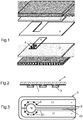
- the roofs have several panels juxtaposed to cover as much of the surface as possible.
- the different parts may consist of glazing with the same composition, that is to say offering the same functionality, they can also be dedicated to different functions.
- the glazing of the figure 1 comprises two sheets of glass, external 1, and internal 2. Most frequently these two sheets are highly absorbent colored glass, so that the light transmission is limited for example to less than 50%, and in a configuration of this type preferably less than 30%.
- the two sheets may be of the same composition or not, but their combined coloring is such that the color in transmission is neutral.
- Glasses used for these sheets are for example gray glasses as described in the patent FR2738238 or in the patent EP1680371 , or gray glasses with a green shade as described in EP 887320 , or in blue nuance as in EP1140718 .
- the glass sheets are presented without enamelled patterns that traditionally are used to hide the edges of the glazing.
- Enamels of this type would for example be arranged on the inner face of the sheet 1, thus in position 2, concealing all the collages and connections located at the edge of the glazing.
- the masking enamels may also be in position 4, in other words on the face of the glazing exposed inside the passenger compartment. But in this position, for an observation of the outside of the vehicle, they do not mask the elements included in the laminated. It is also possible to have the masks in position 2 and in position 4.
- the support of the diodes 6 is constituted by a clear glass plate 5 (for example 0.4 mm thick).
- the diodes 6 are soldered or glued on the supply circuit constituted in a conductive oxide layer not shown.
- the height of the diodes on the glass slide 5 is, for example, 0.6 mm.
- Sheets of thermoplastic material 3 (thickness 0.38mm), 3 '(thickness 1.14mm) and 4 (thickness 0.38mm), PVB type complete the set. Sheets 3, 3 'and 4 are also transparent. To facilitate the insertion of the blade 5 carrying the diodes the sheet 4 is of a thickness close to that of the blade 5, and comprises a cut corresponding to the dimensions of this blade.
- the interlayer sheets submitted to the oven and under vacuum stick to each other and to the glass sheets.
- the maintained vacuum allows the evacuation of air bubbles that could be trapped.
- the intermediate material is sufficiently softened so that the diodes enter the sheet 3 'without requiring excessive pressure.
- the position of the diodes fixed on the sheet 5 remains that which is theirs before this assembly.
- the glass sheets 1 and 2 are respectively 2.1 mm and 2.1 mm thick.
- the assembled glazing has a total thickness of 6.1mm.
- the sheet 1 is of a green glass whose optical characteristics are under 4mm of thickness and an illuminant A: TL A4 27.3%; TE4 14.8%; ⁇ D 486nm; P 18 ( ⁇ D is the dominant wavelength and P is the excitation purity).
- the sheet 2 is gray glass whose characteristics are: TL A4 17%; TE4 15%; ⁇ D 490nm; P 1.8
- the assembled glazing has the following optical characteristics: TL 19%; TE 12%; ⁇ D 493nm; P8; and a color rendering index of 78.
- the figure 2 schematically shows in section the glass plate 5 on which is applied the conductive layer 7 cut to form the diode supply circuit 6.
- the diodes are soldered to this layer. They are gathered on a limited surface to lead to a concentrated beam of sufficient power.
- the conductive circuit is constituted so as to separate the power poles, each diode being soldered to each of the two poles.
- a schematic circuit is for example presented to the figure 3 .
- the blade 5 seen from above, has a conductive layer which is applied to the major part of the blade.
- the layer is divided to form the supply circuit of the diodes shown in 6.
- the layer is in two symmetrical parts retaining a large area to dissipate as much as possible the heat produced in this layer by Joule effect.
- the dimensions of the surfaces of these conductors are also determined so as to ensure a substantially identical supply current for each of the diodes.
- the arrangement of these which is of the "parallel" type along these conductors can lead to a difference in the current flowing through the different diodes.
- the configuration of the electrodes is chosen so as to minimize these differences and the power delivered.
- Each part feeds 4 diodes and is itself divided into two (17 and 18) each corresponding to a power pole (+, -).
- the diodes 6 are each connected to the two poles.
- the layer 7 initially extends uniformly over the entire surface of the glass sheet 5 with possibly uncoated edges.
- the separation of the different zones in this layer is obtained according to lines 21, drawn in this layer for example by ablation by means of a laser by prior methods well known.
- the width of the ablation is limited to what is necessary to ensure that the areas are electrically isolated from each other.
- the distribution of the diodes is made so as to distribute as best as possible the heat produced during operation.
- the diodes are spaced from each other, but at a distance limited by the need to collect the resulting light emission.
- the diodes are arranged in a circle of diameter 6 cm.
- the conductive layer is an ITO layer ("indium tin oxide”) of 10 ⁇ / ⁇ of resistance.
- ITO layer indium tin oxide
- the ITO layer is interesting especially because of its color neutrality. It does not significantly change the aspect in transmission in particular.
- the figure 3 also has an electrode 19 cut in the conductive layer, as the supply circuit of the diodes.
- This electrode is connected to an assembly controlling the diode switch in a capacitance type circuit.
- the charge time of the electrode is controlled by its capacity itself varying according to the conductive elements placed in the vicinity and which modify the electromagnetic field. The movement of the operator in this direction, thus triggers a diode switch relay.
- the circuit in a known manner may also include a dimmer which leads to different power levels for lighting of varying intensity, each pulse passing from one level to another.
- the connecting conductor 20 of the electrode 19 to the device not shown is of as small a surface as possible.
- a conductive screen connected to the ground is advantageously interposed. between this electrode and the outside of the roof.
- This screen can take the form of a conductive thin layer. This thin layer may for example cover the other face of the blade 5.
- the electrode 19 and the conductor 20 which connects it to the switch device may be surrounded by a conductive zone also cut in the layer and connected to the mass, to also reduce the possible incidence of neighboring electric fields.
- the conditions fixed for a reading light are for example to have a given sufficient illumination on a given surface and at a distance.
- the distance is 0.6m between the roof and the surface to be illuminated which is fixed to a circle radius 0.25m.
- the minimum illumination required on this surface is for example 55 lux.
- the diodes used are of Nichia brand type NS2W150A. These are medium power diodes producing a "cold white” light. They are powered at a voltage of 3.2v and each under an intensity of 0.100A.
- the light intensity given by the manufacturer is 17.4cd for an intensity of 0.150A. It can be estimated on the domain considered that the luminous intensity is approximately proportional to the electrical intensity. This light intensity according to the normal to the diode is thus established at about 11.6cd. It varies according to the direction considered as shown in the graph of the figure 4 .
- the luminous intensity for a diode is about 10.45cd. It takes into account the impact of the insertion of the diodes into the laminate, including reflections and light absorption in the path of the beam. Finally to reach the necessary illumination it takes about 8 diodes of this type to constitute the reading light.
- the fact of using a plurality of limited power diodes outside the control of local heating also reduces the glare effect that can come from direct observation of the diodes. This effect can be further minimized by promoting a certain diffusion of the light beam for example by a frosted of the inner sheet at the location corresponding to the diodes.
- the luminous flux emitted by the diodes is characterized by colorimetric coordinates shown on the diagram of the figure 8 and represented by the boundaries generally denoted by N.
- the domain as presented by the manufacturer is subdivided into parts corresponding to separate classes left to the choice of the user.
- the manufacturer proposes if necessary a preliminary sorting so that all the diodes are located in only one of these parts. This selection which allows to refine the color is accompanied by an additional cost.
- the perimeter P corresponding to the preferred color according to the invention. Note that this color which largely covers that of the diodes, also takes into account the incidence of the glass sheet which is interposed between the diodes and the passenger compartment, and possibly the interlayer if it is chosen from color.
- the diodes emit a stream of slightly bluish white light that is described as "cold". If a "hot” light is preferred, one can choose a product of the same type as that of Nichia referenced NS2L150A. The spectrum of these diodes corresponds to the perimeter designated by M.
- the arrangement of the 8 diodes in the laminate does not lead to a harmful heating.
- the temperature rises to about 35 ° C. These temperatures do not alter the diodes or the components of the glazing.
- the luminous flux emitted by the diodes chosen is distributed as shown in the graph of the figure 4 .
- This graph shows the horizontal scale of the luminous intensities.
- the concentric semicircles have intensity fractions from 0 to 100% of the highest intensity that is vertical.
- the intensity is read on the graph at the intersection of the line corresponding to the direction with the circle C.
- the light intensity decreases rapidly with increasing angle from the normal at the source. It is only about half for an angle of 60 °. This distribution can be satisfactory if, outside the surface that we want to illuminate, it is not embarrassing to have a certain brightness. In the opposite case it is necessary to restrict the light beam.
- the figure 5 schematically shows in section, a roof glazing side comprising a set of diodes 6, on a support 5 consisting of a glass slide.
- the set of diodes 6 and their support 5 is incorporated as previously in a material formed from several plastic spacers (3,4,3 ').
- the figure 5 illustrates that the luminous flux emitted by the diodes 6 is distributed in a broadly open beam. Without any device other than the reflector which is part of the diode envelope, the initial flux develops at an angle at the origin, ie in the intermediate material and in the sheet 2, which can go up to 180 ° and is not usually less than 120 ° depending on the configuration of the diode envelope. This is represented by the angle ⁇ 1 .
- FIG 5 schematically illustrates the use of a Fresnel optics 8 on the face 4 of the glazing facing the diodes. The beam is thus reduced to a smaller angle ⁇ 2 .
- the diaphragm may be constituted in an opaque enamelled pattern 9 applied to the face of the glass sheet 2 facing the passenger compartment. This arrangement must be applied to each diode individually. It is therefore necessary that the respective positions of the diodes and the openings in the opaque enamel layer are rigorously established.
- the graph of the figure 4 illustrates the effect of an example of this mode of limiting the beam by diaphragm.
- the diaphragm is schematized by the two arrows defining its opening.
- the enamel 9 is disposed at 3mm from the source whose size is that of a diode, about 2.5mm.
- the free enamel opening is 0.5mm. In this configuration the beam opens at 48 ° angle.
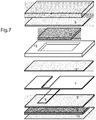
- the figure 6 schematically illustrates the use of a low-emissive layer system 10, applied in position 4. In this position the layers are not protected against mechanical or chemical alterations from the passenger compartment. This provision is nevertheless necessary to achieve the required efficiency.
- the oxide-based layers obtained by pyrolysis offer good mechanical strength.
- the most common "low-e" (low-emissive) pyrolytic systems comprise a layer of doped tin oxide deposited on a first layer whose function is to neutralize the color in reflection.
- the layer in contact with the glass is usually a layer of silica or silicon oxy-carbide, optionally modified with additives.
- the tin oxide layers compared to the layers of the systems deposited by cathodic sputtering, are relatively thick, more than 200 nm, and for some more than 450 nm. These thick layers are strong enough to withstand being exposed to mechanical and / or chemical tests.
- An example of a low-e system having the desired properties consists of a layer of tin oxide doped with 2 atomic% fluorine, whose thickness is 470 nm. This layer is deposited on a layer in contact with glass, composed of silicon oxy-carbide 75nm thick. This system on a clear glass sheet 4mm thick leads to an emissivity of about 0.1.
- Low-e layer systems can be produced by a sputtering technique while maintaining sufficient mechanical strength.
- Systems of this type are for example composed of oxides, in particular layers based on titanium oxide in combination with other metal oxides, in particular zirconium oxide. Layers of this type are described in particular in the application WO2010 / 031808 .
- a usable system comprises a layer of an alloy of chromium and zirconium. To protect this metal layer deposited by cathode sputtering, it is sandwiched between two layers of silicon nitride. This set also leads to a satisfactory emissivity with a reduction in light transmission that can reach 10%, which reduction for the use considered is not a disadvantage.
- the glazed roofs according to the invention can advantageously combine several functionalities. Among these it is interesting to benefit from the glazed roof for lighting, as developed above, but also to have a controlled variation of the light transmission, whether or not this variation is implemented simultaneously.
- the principle of the application of SPD cells for automotive roofs with controlled light transmission is well known.
- the use of these films makes it possible to modify very significantly the transmission between two distinct states, a clear state and an obscure state.
- An interest of these systems is, in the dark state, to achieve the almost complete suppression of the light transmission.
- the commercially available films thus make it possible to reduce the transmission in the visible to less than 1%. This is the state that corresponds to the absence of an electric field. In these conditions the glazing ensures the "private" character sought in a particularly effective manner.
- the visible light transmission variation can be as high as 40% or more between the two states of the film.
- the choice of films makes it possible, if necessary, to determine the importance of this variation. Users favor relatively large deviations, and generally these are not less than 30% in the intended applications.
- SPD films these have an important role in the energy transmission of the glazing in which they are incorporated.
- the energetic transmission independently of the presence of glass sheets or absorbent inserts, is usually less than 5%.
- the dark state is normally that of the stationary vehicle, a very limited energy transmission is therefore particularly welcome.
- the energetic transmission is appreciably more important because the visible radiation is also accompanied by energetic transmission.
- the SPD film nevertheless absorbs a significant part of the energy.
- SPD films are subject to some requirements apart from those concerning their performance on the modification of the light transmission. Firstly, it is necessary to protect the functional film mechanically and chemically.
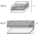
- the figure 7 illustrates the composition of a roof offering both features, lighting and controlled light transmission.
- the roof of the figure 1 we find the two sheets of glass 1 and 2 and the spacers 3, 3 'and 4, and the blade 5 support diodes.
- the SPD film is shown schematically at 12. It does not cover the entire glazing. The edges of the SPD film should be protected from contact with the outside atmosphere, especially to protect the active particles from moisture. To prevent contact with the atmosphere, the SPD 12 film is completely wrapped in the different sheets of interlayer material. To wrap the film 12, an interlayer sheet 13 of thickness close to that of the film is arranged so as to surround it. An appropriate cut of the sheet 13 makes it possible to surround the film to isolate it from the outside.
- the figure 7 shows the sheet 13 consists of a single piece in which a recess is arranged. It is possible to replace this single piece with a set of juxtaposed strips surrounding the film 12 in an equivalent manner. The presence of this sheet 13 isolates the SPD film and simultaneously ensures a uniform distribution of the pressure exerted on the constituents of the glazing during its assembly.
- the sheet 13 may or may not be of the same nature as the tabs 3 and 4. The merging of the different sheets during assembly is facilitated if these sheets are of the same nature.
- SPD films Another requirement of SPD films is related to their sensitivity to heat.
- particles that are usually incorporated in a polymer matrix can be altered by excessive temperature rise.
- the films can be irreversibly modified if they are exposed to too intense cold, for example of -40 ° C.
- the exposure to external temperature variations is accentuated by the position envisaged according to the invention.
- Solar radiation, and especially infrared rays, can lead to a sharp rise in temperature.
- the materials used to form the laminates and encapsulate the cells are usually products that by themselves are UV screens. This is particularly the case for materials such as polyvinyl butyrals (PVB) or ethylene-vinyl-acetate polymers (EVA), previously presented for producing the laminated structures of these roofs. The presence of such compounds is an almost complete UV filter. It is therefore not necessary to provide additional elements.
- PVB polyvinyl butyrals
- EVA ethylene-vinyl-acetate polymers
- the functional elements present in the laminate are in relative positions that take into account their possible interdependence.
- the illumination means constituted by the light-emitting diodes are of course located under the film for controlling the light transmission, so that the luminous flux that they produce is independent of the variations in light absorption imposed by this film. .
- the control film of the light transmission as the lighting means are necessarily electrically powered. Their connection to the general power system of the vehicle is necessarily made from the edges of the glazing. Electrical connection leads are not normally transparent. In order not to break the even limited transparency of the glazing, efforts are made to conceal these pipes in the peripheral zones of the glazing, which normally include opaque enamelled parts intended in particular to mask the irregular gluing marks. These masks also hide the boundaries of SPD 12 films with their entourage 13. The figure 7 does not represent these enamelled strips.
- the structure of the SPD type films described in the application WO2005 / 102688 is schematized at the figure 7a .
- This structure comprises a central element 15 consisting of a polymer containing the particles sensitive to the application of the electric field.
- two electrodes 16 make it possible to apply the voltage necessary for the control.
- the electrodes 16 are advantageously consist of essentially transparent sheets coated with thin conductive layers. Most commonly polyethylene terephthalate (PET) sheets of a few tens of microns thick which combine good transparency with high mechanical strength.
- PET polyethylene terephthalate
- the conductive layers are advantageously of the TCO (thin conductive oxide) type, such as the ITO (indium tin oxide) layers.
- the components of the SPD films are sensitive to aging, in particular under the effect of heat.
- the film is normally protected by filters interposed between the outer glass sheet 1 exposed to solar radiation, and the SPD film 15.
- Infrared filters are used in many applications in sunscreen or glazing low-emissivity. They generally consist of thin layers of conductive oxides, or better, because much more efficient metal layers thin enough to be virtually transparent.
- the metal layers are associated with thin and transparent dielectric layers which give the assembly the necessary selectivity. Most often to improve this selectivity, which is accompanied by reflection that is striven to make as neutral as possible, the filters comprise a plurality of metal layers which are essentially based on silver.
- the infrared filtering layers are either applied to the outer glass sheet or introduced via an intermediate polymer sheet, in particular of the PET type.
- the figure 7b shows a detail of an assembly of this type in which under the outer glass sheet 1, a sheet 14 carrying the infrared filter is disposed between two sheets 3 and 20 of interlayer material.
- a sheet 14 carrying the infrared filter is disposed between two sheets 3 and 20 of interlayer material.
- the support of the PET-type layers is not itself such as to adhere to the glass, it is necessary to introduce it between two thermoplastic interlayer sheets.
- the use of a support film makes it possible not to subject the fragile layers to high temperatures. The only constraint remains the temperature imposed by passing to the oven at the time of assembly.
- the counterpart is the fact of having to add an interlayer sheet which increases the thickness of the whole.
- the choice of the layer system is advantageously that of multilayered silver systems to obtain an effective filter and which allows the control of the color especially in reflection.
- a particularly effective set of layers is as described in the application WO2011 / 147875 .
- the recommended system comprises three silver layers and dielectric layers, the assembly being chosen, in particular the thicknesses of the silver layers, so that the coloration in reflection is satisfactory even at low observation angles. .
- the protection of the SPD film must also take into account the presence of the diodes when they are arranged in parts of the roof surface covered by this film.
- the example given above shows, by a suitable choice of diodes and their arrangement, that it is possible to limit the local temperature increase related to the operation of the diodes to a few tens of degrees. This increase remains in all cases lower than that related to exposure to solar radiation.
Landscapes
- Engineering & Computer Science (AREA)
- Mechanical Engineering (AREA)
- General Engineering & Computer Science (AREA)
- Physics & Mathematics (AREA)
- Spectroscopy & Molecular Physics (AREA)
- Crystallography & Structural Chemistry (AREA)
- Chemical & Material Sciences (AREA)
- Joining Of Glass To Other Materials (AREA)
- Arrangements Of Lighting Devices For Vehicle Interiors, Mounting And Supporting Thereof, Circuits Therefore (AREA)
- Laminated Bodies (AREA)
- Body Structure For Vehicles (AREA)
- Fastening Of Light Sources Or Lamp Holders (AREA)
- Arrangement Of Elements, Cooling, Sealing, Or The Like Of Lighting Devices (AREA)
- Glass Compositions (AREA)
Applications Claiming Priority (2)
| Application Number | Priority Date | Filing Date | Title |
|---|---|---|---|
| BE201200411A BE1020716A3 (fr) | 2012-06-19 | 2012-06-19 | Toit vitre comportant des moyens d'eclairage et de controle de la transmission lumineuse. |
| PCT/EP2013/062112 WO2013189796A1 (fr) | 2012-06-19 | 2013-06-12 | Toit vitré comportant des moyens d'éclairage et de contrôle de la transmission lumineuse |
Publications (2)
| Publication Number | Publication Date |
|---|---|
| EP2861422A1 EP2861422A1 (fr) | 2015-04-22 |
| EP2861422B1 true EP2861422B1 (fr) | 2019-03-06 |
Family
ID=46798908
Family Applications (1)
| Application Number | Title | Priority Date | Filing Date |
|---|---|---|---|
| EP13731058.7A Active EP2861422B1 (fr) | 2012-06-19 | 2013-06-12 | Toit vitré comportant des moyens d'éclairage et de contrôle de la transmission lumineuse |
Country Status (10)
| Country | Link |
|---|---|
| US (1) | US10139080B2 (enExample) |
| EP (1) | EP2861422B1 (enExample) |
| JP (1) | JP6594203B2 (enExample) |
| KR (1) | KR102064404B1 (enExample) |
| CN (1) | CN104379344A (enExample) |
| BE (1) | BE1020716A3 (enExample) |
| BR (1) | BR112014031612B8 (enExample) |
| EA (1) | EA029308B1 (enExample) |
| IN (1) | IN2014DN11188A (enExample) |
| WO (1) | WO2013189796A1 (enExample) |
Families Citing this family (32)
| Publication number | Priority date | Publication date | Assignee | Title |
|---|---|---|---|---|
| US10394232B2 (en) * | 2015-02-27 | 2019-08-27 | Research Frontiers Incorporated | Control system for SPD device and home automation |
| US10099800B2 (en) * | 2015-05-08 | 2018-10-16 | The Boeing Company | Structurally embedded lighting for display panels and method of making the same |
| JP6605723B2 (ja) * | 2015-12-07 | 2019-11-13 | サン−ゴバン グラス フランス | 光センサが組み込まれた車両用合わせガラス |
| US10642568B2 (en) * | 2016-01-06 | 2020-05-05 | Hewlett-Packard Development Company, L.P. | Projector and electronic ink display |
| US10532636B2 (en) | 2016-04-01 | 2020-01-14 | AGC Inc. | Laminated glass for vehicle |
| JP2017186229A (ja) * | 2016-04-01 | 2017-10-12 | 旭硝子株式会社 | 車両用合わせガラス |
| FR3051727B1 (fr) * | 2016-05-26 | 2018-05-18 | Saint-Gobain Glass France | Vitrage de signalisation lumineuse, vehicule l'incorporant et fabrication. |
| MA45361A (fr) * | 2016-05-26 | 2019-04-10 | Saint Gobain | Toit vitre feuillete lumineux de vehicule, vehicule l'incorporant et fabrication |
| EP3264242A1 (en) * | 2016-06-29 | 2018-01-03 | Saint-Gobain Glass France | Touch control glazing with a capacitive touch sensitive device and a light emitting diode and the manufacturing |
| EP3264241A1 (en) * | 2016-06-29 | 2018-01-03 | Saint-Gobain Glass France | Lighting laminated glazing with a capacitive touch sensitive device and a light emitting diode and the manufacturing |
| KR101905989B1 (ko) * | 2016-10-24 | 2018-10-08 | 현대자동차주식회사 | 차량용 접합글라스 디스플레이 |
| EP3535121B1 (de) | 2016-11-02 | 2023-10-25 | Saint-Gobain Glass France | Verfahren zur herstellung einer verbundscheibe mit funktionselement |
| JP6760150B2 (ja) * | 2017-03-13 | 2020-09-23 | フジテック株式会社 | マンコンベア |
| JP7021261B2 (ja) * | 2017-03-15 | 2022-02-16 | サン-ゴバン グラス フランス | 電気機器を有するガラスペイン |
| BR112019023488A2 (pt) * | 2017-05-24 | 2020-05-19 | Saint Gobain | painel de vidro laminado e método para produção do mesmo |
| US10193494B2 (en) | 2017-05-26 | 2019-01-29 | Ford Global Technologies, Llc | Vehicle glass roof systems |
| CO2018000469A1 (es) | 2017-11-30 | 2018-04-30 | Agp America Sa | Laminado automotriz con capa de compensación de sustrato de borde sólido invisible |
| MX2020005856A (es) * | 2017-12-05 | 2020-09-09 | Saint Gobain | Cristal compuesto que tiene recubrimiento de proteccion solar y recubrimiento que refleja radiacion termica. |
| EP3518616A1 (en) | 2018-01-26 | 2019-07-31 | AGC Glass Europe | Method and arrangement for de-icing a transparent window using an electric heating device |
| JP7137634B2 (ja) | 2018-04-25 | 2022-09-14 | サン-ゴバン グラス フランス | 熱可塑性中間層に電気的に切り換え可能な機能要素を有する複合ペイン |
| DE102018211019B4 (de) | 2018-07-04 | 2025-05-15 | Bayerische Motoren Werke Aktiengesellschaft | Bedieneinheit eines Fahrzeugs |
| US11286199B2 (en) | 2019-07-01 | 2022-03-29 | Agc Automotive Americas Co., A Division Of Agc Flat Glass North America Inc. | Substantially transparent substrates including high and low emissivity coating layers |
| JP2022130753A (ja) * | 2019-07-23 | 2022-09-07 | Agc株式会社 | 合わせガラス |
| DE102019121358A1 (de) | 2019-08-07 | 2021-02-11 | OSRAM Opto Semiconductors Gesellschaft mit beschränkter Haftung | Licht emittierendes fensterelement und kraftfahrzeug mit licht emittierendem fensterelement |
| CN112752652A (zh) * | 2019-08-28 | 2021-05-04 | 法国圣戈班玻璃厂 | 具有集成的遮阳板的复合玻璃板及其制造方法 |
| JP2022169820A (ja) * | 2019-10-03 | 2022-11-10 | Agc株式会社 | 合わせガラス |
| WO2022249201A1 (en) * | 2021-05-27 | 2022-12-01 | Saint-Gobain Glass France | Laminated structure with micro light emissive unit for display in vehicle |
| DE102021120806A1 (de) * | 2021-08-10 | 2023-02-16 | OSRAM Opto Semiconductors Gesellschaft mit beschränkter Haftung | Fahrzeugscheibe und verfahren zu deren herstellung |
| DE102021125960B4 (de) * | 2021-10-06 | 2023-04-27 | Diehl Aerospace Gmbh | Beleuchtung für ein Fenster eines Flugzeuges |
| WO2023127511A1 (ja) * | 2021-12-27 | 2023-07-06 | ソニーグループ株式会社 | 照明制御装置、照明制御方法、及び、車両 |
| US12311638B2 (en) * | 2022-01-31 | 2025-05-27 | Saint-Gobain Glass France | Laminated pane with light source |
| CN118418673A (zh) * | 2023-07-20 | 2024-08-02 | 法国圣戈班玻璃公司 | 玻璃组件及窗体总成 |
Family Cites Families (24)
| Publication number | Priority date | Publication date | Assignee | Title |
|---|---|---|---|---|
| IT1284767B1 (it) | 1995-09-06 | 1998-05-21 | Glaverbel | Vetro calcio sodico grigio scuro intenso |
| FR2752570B1 (fr) * | 1996-08-22 | 1998-10-02 | Saint Gobain Vitrage | Vitrage a proprietes optiques et/ou energetiques variables |
| LU90084B1 (fr) | 1997-06-25 | 1998-12-28 | Glaverbel | Verre vert fonc sodo-calcique |
| JP4149050B2 (ja) * | 1998-10-06 | 2008-09-10 | 三井化学株式会社 | 赤外線吸収フィルター |
| EP1013620A1 (fr) | 1998-12-22 | 2000-06-28 | Glaverbel | Verre sodo-calcique à nuance bleue |
| AU4548500A (en) | 1999-04-13 | 2000-11-14 | Glaverbel | Glazing for the roof of a motor vehicle |
| BE1012766A3 (fr) | 1999-06-30 | 2001-03-06 | Glaverbel | Vitrage notamment pour toit de vehicule. |
| DE10204359B4 (de) * | 2001-03-25 | 2005-05-04 | Webasto Ag | Fahrzeugdach |
| BE1015302A3 (fr) | 2003-01-10 | 2005-01-11 | Glaverbel | Vitrage comportant des composants electroniques. |
| BE1015646A3 (fr) | 2003-08-13 | 2005-07-05 | Glaverbel | Verre a faible transmission lumineuse. |
| JP4225872B2 (ja) * | 2003-10-01 | 2009-02-18 | 八千代工業株式会社 | 照明機能を備えた車両用サンルーフパネル |
| PL1735156T3 (pl) | 2004-04-13 | 2017-01-31 | Research Frontiers Incorporated | Sposoby laminowania folii do zaworów świetlnych SPD i zawory świetlne SPD zawierające takie folie laminowane |
| WO2007061033A1 (ja) * | 2005-11-28 | 2007-05-31 | Sharp Kabushiki Kaisha | 照明装置とその製造方法 |
| GB0600215D0 (en) * | 2006-01-06 | 2006-02-15 | Pilkington Automotive D Gmbh | Vehicle glazing |
| EP1979160A1 (fr) | 2006-01-25 | 2008-10-15 | AGC Flat Glass Europe SA | Vitrage automobile |
| GB0602933D0 (en) * | 2006-02-14 | 2006-03-22 | Pilkington Automotive Ltd | Vehicle glazing |
| GB0607743D0 (en) * | 2006-04-20 | 2006-05-31 | Pilkington Plc | Laminated glazing |
| EP2147248B1 (en) * | 2007-04-19 | 2010-08-04 | Koninklijke Philips Electronics N.V. | Light output device and control method |
| RU2536071C2 (ru) | 2008-09-17 | 2014-12-20 | Агк Гласс Юроп | Остекление с высокой отражательной способностью |
| GB0916379D0 (en) * | 2009-09-18 | 2009-10-28 | Pilkington Group Ltd | Laminated glazing |
| JP2011088784A (ja) * | 2009-10-22 | 2011-05-06 | Sekisui Chem Co Ltd | 合わせガラス用中間膜及び合わせガラス |
| WO2011145168A1 (ja) * | 2010-05-18 | 2011-11-24 | 住友金属工業株式会社 | 板材の平坦度測定方法及びこれを用いた鋼板の製造方法 |
| BE1019346A3 (fr) | 2010-05-25 | 2012-06-05 | Agc Glass Europe | Vitrage de controle solaire. |
| JP5015301B2 (ja) * | 2010-08-02 | 2012-08-29 | 株式会社フジクラ | 照明器具 |
-
2012
- 2012-06-19 BE BE201200411A patent/BE1020716A3/fr active
-
2013
- 2013-06-12 WO PCT/EP2013/062112 patent/WO2013189796A1/fr not_active Ceased
- 2013-06-12 BR BR112014031612A patent/BR112014031612B8/pt active IP Right Grant
- 2013-06-12 US US14/409,260 patent/US10139080B2/en active Active
- 2013-06-12 IN IN11188DEN2014 patent/IN2014DN11188A/en unknown
- 2013-06-12 CN CN201380032497.9A patent/CN104379344A/zh active Pending
- 2013-06-12 KR KR1020157000853A patent/KR102064404B1/ko active Active
- 2013-06-12 JP JP2015517676A patent/JP6594203B2/ja active Active
- 2013-06-12 EA EA201492076A patent/EA029308B1/ru not_active IP Right Cessation
- 2013-06-12 EP EP13731058.7A patent/EP2861422B1/fr active Active
Non-Patent Citations (1)
| Title |
|---|
| None * |
Also Published As
| Publication number | Publication date |
|---|---|
| EA201492076A1 (ru) | 2015-04-30 |
| WO2013189796A1 (fr) | 2013-12-27 |
| US10139080B2 (en) | 2018-11-27 |
| EA029308B1 (ru) | 2018-03-30 |
| IN2014DN11188A (enExample) | 2015-10-02 |
| US20150165965A1 (en) | 2015-06-18 |
| KR20150031282A (ko) | 2015-03-23 |
| EP2861422A1 (fr) | 2015-04-22 |
| BR112014031612B1 (pt) | 2021-08-03 |
| JP6594203B2 (ja) | 2019-10-23 |
| CN104379344A (zh) | 2015-02-25 |
| KR102064404B1 (ko) | 2020-01-09 |
| BR112014031612B8 (pt) | 2022-03-15 |
| BR112014031612A2 (pt) | 2017-06-27 |
| BE1020716A3 (fr) | 2014-04-01 |
| JP2015529587A (ja) | 2015-10-08 |
Similar Documents
| Publication | Publication Date | Title |
|---|---|---|
| EP2861422B1 (fr) | Toit vitré comportant des moyens d'éclairage et de contrôle de la transmission lumineuse | |
| BE1020715A3 (fr) | Toit vitre comportant des moyens d'eclairage. | |
| EP3079905B1 (fr) | Toit de véhicule vitré | |
| EP3319794B1 (fr) | Vitrage automobile | |
| EP3079903B1 (fr) | Vitrage automobile | |
| EP2861423B1 (fr) | Toit de véhicule | |
| CA3025135A1 (fr) | Toit vitre feuillete lumineux de vehicule, vehicule l'incorporant et fabrication | |
| EP3717239A1 (fr) | Toit vitre de vehicule, vehicule l'incorporant et fabrication | |
| WO2018078278A1 (fr) | Vitrage lumineux de véhicule, véhicule l'incorporant | |
| CA3025132A1 (fr) | Toit vitre feuillete lumineux de vehicule, vehicule l'incorporant et fabrication | |
| EP3034297A1 (fr) | Vitrage feuilleté | |
| FR3074090B1 (fr) | Vitrage de vehicule a signalisation lumineuse externe, vehicule l'incorporant et fabrication. | |
| EP3717304A1 (fr) | Vitrage de vehicule a signalisation lumineuse externe, vehicule l'incorporant et fabrication | |
| EP3463981A1 (fr) | Toit vitre feuillete lumineux de vehicule, vehicule l'incorporant et fabrication | |
| EP2964463B1 (fr) | Toit de vehicule |
Legal Events
| Date | Code | Title | Description |
|---|---|---|---|
| PUAI | Public reference made under article 153(3) epc to a published international application that has entered the european phase |
Free format text: ORIGINAL CODE: 0009012 |
|
| 17P | Request for examination filed |
Effective date: 20150119 |
|
| AK | Designated contracting states |
Kind code of ref document: A1 Designated state(s): AL AT BE BG CH CY CZ DE DK EE ES FI FR GB GR HR HU IE IS IT LI LT LU LV MC MK MT NL NO PL PT RO RS SE SI SK SM TR |
|
| AX | Request for extension of the european patent |
Extension state: BA ME |
|
| DAX | Request for extension of the european patent (deleted) | ||
| STAA | Information on the status of an ep patent application or granted ep patent |
Free format text: STATUS: EXAMINATION IS IN PROGRESS |
|
| 17Q | First examination report despatched |
Effective date: 20180215 |
|
| GRAP | Despatch of communication of intention to grant a patent |
Free format text: ORIGINAL CODE: EPIDOSNIGR1 |
|
| STAA | Information on the status of an ep patent application or granted ep patent |
Free format text: STATUS: GRANT OF PATENT IS INTENDED |
|
| RIC1 | Information provided on ipc code assigned before grant |
Ipc: B60Q 3/76 20170101ALI20180813BHEP Ipc: F21V 14/00 20180101ALN20180813BHEP Ipc: B60Q 3/208 20170101ALI20180813BHEP Ipc: C03C 27/12 20060101ALI20180813BHEP Ipc: B32B 17/10 20060101AFI20180813BHEP |
|
| INTG | Intention to grant announced |
Effective date: 20180914 |
|
| GRAS | Grant fee paid |
Free format text: ORIGINAL CODE: EPIDOSNIGR3 |
|
| GRAA | (expected) grant |
Free format text: ORIGINAL CODE: 0009210 |
|
| STAA | Information on the status of an ep patent application or granted ep patent |
Free format text: STATUS: THE PATENT HAS BEEN GRANTED |
|
| AK | Designated contracting states |
Kind code of ref document: B1 Designated state(s): AL AT BE BG CH CY CZ DE DK EE ES FI FR GB GR HR HU IE IS IT LI LT LU LV MC MK MT NL NO PL PT RO RS SE SI SK SM TR |
|
| REG | Reference to a national code |
Ref country code: GB Ref legal event code: FG4D Free format text: NOT ENGLISH |
|
| REG | Reference to a national code |
Ref country code: CH Ref legal event code: EP Ref country code: AT Ref legal event code: REF Ref document number: 1103993 Country of ref document: AT Kind code of ref document: T Effective date: 20190315 |
|
| REG | Reference to a national code |
Ref country code: DE Ref legal event code: R096 Ref document number: 602013051811 Country of ref document: DE |
|
| REG | Reference to a national code |
Ref country code: IE Ref legal event code: FG4D Free format text: LANGUAGE OF EP DOCUMENT: FRENCH |
|
| REG | Reference to a national code |
Ref country code: NL Ref legal event code: MP Effective date: 20190306 |
|
| REG | Reference to a national code |
Ref country code: LT Ref legal event code: MG4D |
|
| PG25 | Lapsed in a contracting state [announced via postgrant information from national office to epo] |
Ref country code: NO Free format text: LAPSE BECAUSE OF FAILURE TO SUBMIT A TRANSLATION OF THE DESCRIPTION OR TO PAY THE FEE WITHIN THE PRESCRIBED TIME-LIMIT Effective date: 20190606 Ref country code: LT Free format text: LAPSE BECAUSE OF FAILURE TO SUBMIT A TRANSLATION OF THE DESCRIPTION OR TO PAY THE FEE WITHIN THE PRESCRIBED TIME-LIMIT Effective date: 20190306 Ref country code: FI Free format text: LAPSE BECAUSE OF FAILURE TO SUBMIT A TRANSLATION OF THE DESCRIPTION OR TO PAY THE FEE WITHIN THE PRESCRIBED TIME-LIMIT Effective date: 20190306 Ref country code: SE Free format text: LAPSE BECAUSE OF FAILURE TO SUBMIT A TRANSLATION OF THE DESCRIPTION OR TO PAY THE FEE WITHIN THE PRESCRIBED TIME-LIMIT Effective date: 20190306 |
|
| PG25 | Lapsed in a contracting state [announced via postgrant information from national office to epo] |
Ref country code: BG Free format text: LAPSE BECAUSE OF FAILURE TO SUBMIT A TRANSLATION OF THE DESCRIPTION OR TO PAY THE FEE WITHIN THE PRESCRIBED TIME-LIMIT Effective date: 20190606 Ref country code: HR Free format text: LAPSE BECAUSE OF FAILURE TO SUBMIT A TRANSLATION OF THE DESCRIPTION OR TO PAY THE FEE WITHIN THE PRESCRIBED TIME-LIMIT Effective date: 20190306 Ref country code: LV Free format text: LAPSE BECAUSE OF FAILURE TO SUBMIT A TRANSLATION OF THE DESCRIPTION OR TO PAY THE FEE WITHIN THE PRESCRIBED TIME-LIMIT Effective date: 20190306 Ref country code: GR Free format text: LAPSE BECAUSE OF FAILURE TO SUBMIT A TRANSLATION OF THE DESCRIPTION OR TO PAY THE FEE WITHIN THE PRESCRIBED TIME-LIMIT Effective date: 20190607 Ref country code: NL Free format text: LAPSE BECAUSE OF FAILURE TO SUBMIT A TRANSLATION OF THE DESCRIPTION OR TO PAY THE FEE WITHIN THE PRESCRIBED TIME-LIMIT Effective date: 20190306 Ref country code: RS Free format text: LAPSE BECAUSE OF FAILURE TO SUBMIT A TRANSLATION OF THE DESCRIPTION OR TO PAY THE FEE WITHIN THE PRESCRIBED TIME-LIMIT Effective date: 20190306 |
|
| REG | Reference to a national code |
Ref country code: AT Ref legal event code: MK05 Ref document number: 1103993 Country of ref document: AT Kind code of ref document: T Effective date: 20190306 |
|
| PG25 | Lapsed in a contracting state [announced via postgrant information from national office to epo] |
Ref country code: RO Free format text: LAPSE BECAUSE OF FAILURE TO SUBMIT A TRANSLATION OF THE DESCRIPTION OR TO PAY THE FEE WITHIN THE PRESCRIBED TIME-LIMIT Effective date: 20190306 Ref country code: IT Free format text: LAPSE BECAUSE OF FAILURE TO SUBMIT A TRANSLATION OF THE DESCRIPTION OR TO PAY THE FEE WITHIN THE PRESCRIBED TIME-LIMIT Effective date: 20190306 Ref country code: SK Free format text: LAPSE BECAUSE OF FAILURE TO SUBMIT A TRANSLATION OF THE DESCRIPTION OR TO PAY THE FEE WITHIN THE PRESCRIBED TIME-LIMIT Effective date: 20190306 Ref country code: ES Free format text: LAPSE BECAUSE OF FAILURE TO SUBMIT A TRANSLATION OF THE DESCRIPTION OR TO PAY THE FEE WITHIN THE PRESCRIBED TIME-LIMIT Effective date: 20190306 Ref country code: CZ Free format text: LAPSE BECAUSE OF FAILURE TO SUBMIT A TRANSLATION OF THE DESCRIPTION OR TO PAY THE FEE WITHIN THE PRESCRIBED TIME-LIMIT Effective date: 20190306 Ref country code: EE Free format text: LAPSE BECAUSE OF FAILURE TO SUBMIT A TRANSLATION OF THE DESCRIPTION OR TO PAY THE FEE WITHIN THE PRESCRIBED TIME-LIMIT Effective date: 20190306 Ref country code: AL Free format text: LAPSE BECAUSE OF FAILURE TO SUBMIT A TRANSLATION OF THE DESCRIPTION OR TO PAY THE FEE WITHIN THE PRESCRIBED TIME-LIMIT Effective date: 20190306 Ref country code: PT Free format text: LAPSE BECAUSE OF FAILURE TO SUBMIT A TRANSLATION OF THE DESCRIPTION OR TO PAY THE FEE WITHIN THE PRESCRIBED TIME-LIMIT Effective date: 20190706 |
|
| PG25 | Lapsed in a contracting state [announced via postgrant information from national office to epo] |
Ref country code: PL Free format text: LAPSE BECAUSE OF FAILURE TO SUBMIT A TRANSLATION OF THE DESCRIPTION OR TO PAY THE FEE WITHIN THE PRESCRIBED TIME-LIMIT Effective date: 20190306 Ref country code: SM Free format text: LAPSE BECAUSE OF FAILURE TO SUBMIT A TRANSLATION OF THE DESCRIPTION OR TO PAY THE FEE WITHIN THE PRESCRIBED TIME-LIMIT Effective date: 20190306 |
|
| REG | Reference to a national code |
Ref country code: DE Ref legal event code: R097 Ref document number: 602013051811 Country of ref document: DE |
|
| PG25 | Lapsed in a contracting state [announced via postgrant information from national office to epo] |
Ref country code: IS Free format text: LAPSE BECAUSE OF FAILURE TO SUBMIT A TRANSLATION OF THE DESCRIPTION OR TO PAY THE FEE WITHIN THE PRESCRIBED TIME-LIMIT Effective date: 20190706 Ref country code: AT Free format text: LAPSE BECAUSE OF FAILURE TO SUBMIT A TRANSLATION OF THE DESCRIPTION OR TO PAY THE FEE WITHIN THE PRESCRIBED TIME-LIMIT Effective date: 20190306 |
|
| PLBE | No opposition filed within time limit |
Free format text: ORIGINAL CODE: 0009261 |
|
| STAA | Information on the status of an ep patent application or granted ep patent |
Free format text: STATUS: NO OPPOSITION FILED WITHIN TIME LIMIT |
|
| PG25 | Lapsed in a contracting state [announced via postgrant information from national office to epo] |
Ref country code: MC Free format text: LAPSE BECAUSE OF FAILURE TO SUBMIT A TRANSLATION OF THE DESCRIPTION OR TO PAY THE FEE WITHIN THE PRESCRIBED TIME-LIMIT Effective date: 20190306 Ref country code: DK Free format text: LAPSE BECAUSE OF FAILURE TO SUBMIT A TRANSLATION OF THE DESCRIPTION OR TO PAY THE FEE WITHIN THE PRESCRIBED TIME-LIMIT Effective date: 20190306 |
|
| REG | Reference to a national code |
Ref country code: CH Ref legal event code: PL |
|
| 26N | No opposition filed |
Effective date: 20191209 |
|
| PG25 | Lapsed in a contracting state [announced via postgrant information from national office to epo] |
Ref country code: SI Free format text: LAPSE BECAUSE OF FAILURE TO SUBMIT A TRANSLATION OF THE DESCRIPTION OR TO PAY THE FEE WITHIN THE PRESCRIBED TIME-LIMIT Effective date: 20190306 |
|
| REG | Reference to a national code |
Ref country code: BE Ref legal event code: MM Effective date: 20190630 |
|
| PG25 | Lapsed in a contracting state [announced via postgrant information from national office to epo] |
Ref country code: TR Free format text: LAPSE BECAUSE OF FAILURE TO SUBMIT A TRANSLATION OF THE DESCRIPTION OR TO PAY THE FEE WITHIN THE PRESCRIBED TIME-LIMIT Effective date: 20190306 |
|
| PG25 | Lapsed in a contracting state [announced via postgrant information from national office to epo] |
Ref country code: IE Free format text: LAPSE BECAUSE OF NON-PAYMENT OF DUE FEES Effective date: 20190612 |
|
| PG25 | Lapsed in a contracting state [announced via postgrant information from national office to epo] |
Ref country code: LI Free format text: LAPSE BECAUSE OF NON-PAYMENT OF DUE FEES Effective date: 20190630 Ref country code: CH Free format text: LAPSE BECAUSE OF NON-PAYMENT OF DUE FEES Effective date: 20190630 Ref country code: LU Free format text: LAPSE BECAUSE OF NON-PAYMENT OF DUE FEES Effective date: 20190612 Ref country code: BE Free format text: LAPSE BECAUSE OF NON-PAYMENT OF DUE FEES Effective date: 20190630 |
|
| PG25 | Lapsed in a contracting state [announced via postgrant information from national office to epo] |
Ref country code: CY Free format text: LAPSE BECAUSE OF FAILURE TO SUBMIT A TRANSLATION OF THE DESCRIPTION OR TO PAY THE FEE WITHIN THE PRESCRIBED TIME-LIMIT Effective date: 20190306 |
|
| PG25 | Lapsed in a contracting state [announced via postgrant information from national office to epo] |
Ref country code: MT Free format text: LAPSE BECAUSE OF FAILURE TO SUBMIT A TRANSLATION OF THE DESCRIPTION OR TO PAY THE FEE WITHIN THE PRESCRIBED TIME-LIMIT Effective date: 20190306 Ref country code: HU Free format text: LAPSE BECAUSE OF FAILURE TO SUBMIT A TRANSLATION OF THE DESCRIPTION OR TO PAY THE FEE WITHIN THE PRESCRIBED TIME-LIMIT; INVALID AB INITIO Effective date: 20130612 |
|
| PG25 | Lapsed in a contracting state [announced via postgrant information from national office to epo] |
Ref country code: MK Free format text: LAPSE BECAUSE OF FAILURE TO SUBMIT A TRANSLATION OF THE DESCRIPTION OR TO PAY THE FEE WITHIN THE PRESCRIBED TIME-LIMIT Effective date: 20190306 |
|
| PGFP | Annual fee paid to national office [announced via postgrant information from national office to epo] |
Ref country code: GB Payment date: 20240502 Year of fee payment: 12 |
|
| PGFP | Annual fee paid to national office [announced via postgrant information from national office to epo] |
Ref country code: DE Payment date: 20240502 Year of fee payment: 12 |
|
| P01 | Opt-out of the competence of the unified patent court (upc) registered |
Free format text: CASE NUMBER: APP_37373/2024 Effective date: 20240622 |
|
| PGFP | Annual fee paid to national office [announced via postgrant information from national office to epo] |
Ref country code: FR Payment date: 20240509 Year of fee payment: 12 |