EP2861391B1 - A method for dividing a board into a first panel and a second panel, a method of forming a mechanical locking system for locking of a first and a second panel, and building panels - Google Patents
A method for dividing a board into a first panel and a second panel, a method of forming a mechanical locking system for locking of a first and a second panel, and building panels Download PDFInfo
- Publication number
- EP2861391B1 EP2861391B1 EP13807818.3A EP13807818A EP2861391B1 EP 2861391 B1 EP2861391 B1 EP 2861391B1 EP 13807818 A EP13807818 A EP 13807818A EP 2861391 B1 EP2861391 B1 EP 2861391B1
- Authority
- EP
- European Patent Office
- Prior art keywords
- groove
- locking
- board
- forming
- vertically open
- Prior art date
- Legal status (The legal status is an assumption and is not a legal conclusion. Google has not performed a legal analysis and makes no representation as to the accuracy of the status listed.)
- Active
Links
Images


Classifications
-
- E—FIXED CONSTRUCTIONS
- E04—BUILDING
- E04G—SCAFFOLDING; FORMS; SHUTTERING; BUILDING IMPLEMENTS OR AIDS, OR THEIR USE; HANDLING BUILDING MATERIALS ON THE SITE; REPAIRING, BREAKING-UP OR OTHER WORK ON EXISTING BUILDINGS
- E04G23/00—Working measures on existing buildings
- E04G23/006—Arrangements for removing of previously fixed floor coverings
-
- E—FIXED CONSTRUCTIONS
- E04—BUILDING
- E04B—GENERAL BUILDING CONSTRUCTIONS; WALLS, e.g. PARTITIONS; ROOFS; FLOORS; CEILINGS; INSULATION OR OTHER PROTECTION OF BUILDINGS
- E04B5/00—Floors; Floor construction with regard to insulation; Connections specially adapted therefor
- E04B5/02—Load-carrying floor structures formed substantially of prefabricated units
-
- B—PERFORMING OPERATIONS; TRANSPORTING
- B27—WORKING OR PRESERVING WOOD OR SIMILAR MATERIAL; NAILING OR STAPLING MACHINES IN GENERAL
- B27F—DOVETAILED WORK; TENONS; SLOTTING MACHINES FOR WOOD OR SIMILAR MATERIAL; NAILING OR STAPLING MACHINES
- B27F1/00—Dovetailed work; Tenons; Making tongues or grooves; Groove- and- tongue jointed work; Finger- joints
- B27F1/02—Making tongues or grooves, of indefinite length
-
- B—PERFORMING OPERATIONS; TRANSPORTING
- B27—WORKING OR PRESERVING WOOD OR SIMILAR MATERIAL; NAILING OR STAPLING MACHINES IN GENERAL
- B27M—WORKING OF WOOD NOT PROVIDED FOR IN SUBCLASSES B27B - B27L; MANUFACTURE OF SPECIFIC WOODEN ARTICLES
- B27M3/00—Manufacture or reconditioning of specific semi-finished or finished articles
- B27M3/04—Manufacture or reconditioning of specific semi-finished or finished articles of flooring elements, e.g. parqueting blocks
-
- E—FIXED CONSTRUCTIONS
- E04—BUILDING
- E04F—FINISHING WORK ON BUILDINGS, e.g. STAIRS, FLOORS
- E04F15/00—Flooring
- E04F15/02—Flooring or floor layers composed of a number of similar elements
- E04F15/02038—Flooring or floor layers composed of a number of similar elements characterised by tongue and groove connections between neighbouring flooring elements
-
- E—FIXED CONSTRUCTIONS
- E04—BUILDING
- E04F—FINISHING WORK ON BUILDINGS, e.g. STAIRS, FLOORS
- E04F15/00—Flooring
- E04F15/02—Flooring or floor layers composed of a number of similar elements
- E04F15/04—Flooring or floor layers composed of a number of similar elements only of wood or with a top layer of wood, e.g. with wooden or metal connecting members
- E04F15/041—Flooring or floor layers composed of a number of similar elements only of wood or with a top layer of wood, e.g. with wooden or metal connecting members with a top layer of wood in combination with a lower layer of other material
- E04F15/042—Flooring or floor layers composed of a number of similar elements only of wood or with a top layer of wood, e.g. with wooden or metal connecting members with a top layer of wood in combination with a lower layer of other material the lower layer being of fibrous or chipped material, e.g. bonded with synthetic resins
-
- E—FIXED CONSTRUCTIONS
- E04—BUILDING
- E04F—FINISHING WORK ON BUILDINGS, e.g. STAIRS, FLOORS
- E04F2201/00—Joining sheets or plates or panels
- E04F2201/01—Joining sheets, plates or panels with edges in abutting relationship
- E04F2201/0107—Joining sheets, plates or panels with edges in abutting relationship by moving the sheets, plates or panels substantially in their own plane, perpendicular to the abutting edges
- E04F2201/0115—Joining sheets, plates or panels with edges in abutting relationship by moving the sheets, plates or panels substantially in their own plane, perpendicular to the abutting edges with snap action of the edge connectors
-
- E—FIXED CONSTRUCTIONS
- E04—BUILDING
- E04F—FINISHING WORK ON BUILDINGS, e.g. STAIRS, FLOORS
- E04F2201/00—Joining sheets or plates or panels
- E04F2201/01—Joining sheets, plates or panels with edges in abutting relationship
- E04F2201/0153—Joining sheets, plates or panels with edges in abutting relationship by rotating the sheets, plates or panels around an axis which is parallel to the abutting edges, possibly combined with a sliding movement
-
- E—FIXED CONSTRUCTIONS
- E04—BUILDING
- E04F—FINISHING WORK ON BUILDINGS, e.g. STAIRS, FLOORS
- E04F2201/00—Joining sheets or plates or panels
- E04F2201/02—Non-undercut connections, e.g. tongue and groove connections
- E04F2201/025—Non-undercut connections, e.g. tongue and groove connections with tongue and grooves alternating transversally in the direction of the thickness of the panel, e.g. multiple tongue and grooves oriented parallel to each other
-
- Y—GENERAL TAGGING OF NEW TECHNOLOGICAL DEVELOPMENTS; GENERAL TAGGING OF CROSS-SECTIONAL TECHNOLOGIES SPANNING OVER SEVERAL SECTIONS OF THE IPC; TECHNICAL SUBJECTS COVERED BY FORMER USPC CROSS-REFERENCE ART COLLECTIONS [XRACs] AND DIGESTS
- Y10—TECHNICAL SUBJECTS COVERED BY FORMER USPC
- Y10T—TECHNICAL SUBJECTS COVERED BY FORMER US CLASSIFICATION
- Y10T29/00—Metal working
- Y10T29/49—Method of mechanical manufacture
- Y10T29/49815—Disassembling
- Y10T29/49817—Disassembling with other than ancillary treating or assembling
-
- Y—GENERAL TAGGING OF NEW TECHNOLOGICAL DEVELOPMENTS; GENERAL TAGGING OF CROSS-SECTIONAL TECHNOLOGIES SPANNING OVER SEVERAL SECTIONS OF THE IPC; TECHNICAL SUBJECTS COVERED BY FORMER USPC CROSS-REFERENCE ART COLLECTIONS [XRACs] AND DIGESTS
- Y10—TECHNICAL SUBJECTS COVERED BY FORMER USPC
- Y10T—TECHNICAL SUBJECTS COVERED BY FORMER US CLASSIFICATION
- Y10T29/00—Metal working
- Y10T29/49—Method of mechanical manufacture
- Y10T29/49815—Disassembling
- Y10T29/49819—Disassembling with conveying of work or disassembled work part
Definitions
- Embodiments of the invention generally relate to the field of mechanical locking systems for building panels, especially floorboards. Embodiments of the invention relate to methods for making floorboards with such locking systems.
- Embodiments of the present invention are particularly suitable for use in floating floors, which are formed of floorboards which are joined mechanically with a locking system made in one piece with the core and are made up of one or more upper layers of veneer, decorative laminate or decorative plastic material, an intermediate core of wood-fibre-based material or plastic material and preferably a lower balancing layer on the rear side of the core, and are manufactured by sawing large boards into several panels.
- a locking system made in one piece with the core and are made up of one or more upper layers of veneer, decorative laminate or decorative plastic material, an intermediate core of wood-fibre-based material or plastic material and preferably a lower balancing layer on the rear side of the core, and are manufactured by sawing large boards into several panels.
- the invention may be used in any floorboards or building panels, which are intended to be locked together on two adjacent edges horizontally and vertically with a mechanical locking system that allows locking, preferably by an angling motion.
- Embodiments of the invention may thus also be applicable to, for instance, solid wooden floors, parquet floors with a core of wood lamellas or wood-fibre-based material and the like which are made as separate floor panels, floors with a printed and preferably also varnished surface and the like.
- Embodiments of the invention may also be used for joining building panels, for instance, of wall panels and furniture components.
- Laminate flooring usually comprise of a core of 6-11 mm fibreboard, a 0.1-0.8 mm thick upper decorative surface layer of laminate and a 0.1-0.6 mm thick lower balancing layer of laminate, plastic, paper or like material.
- the surface layer provides appearance and durability to the floorboards.
- the core provides stability, and the balancing layer keeps the board plane after pressing and when the relative humidity (RH) varies during the year.
- the floorboards are laid floating, i.e. without gluing, on an existing subfloor.
- Traditional hard floorboards of this type were usually joined by means of glued tongue-and-groove joints.
- mechanical locking systems comprise locking means, which lock the boards horizontally and vertically.
- the mechanical locking systems are usually formed by machining of the core. Alternatively, parts of the locking system may be formed of separate materials, for example aluminium or plastic, which are factory integrated with the floorboard.
- the most common core material is a fibreboard with high density and good stability usually called HDF - High Density Fibreboard. Sometimes also MDF - Medium Density Fibreboard - is used as core.
- a laminate board which comprises a surface of melamine impregnated decorative paper, plastic, wood, veneer, cork and the like are made by the surface layer and preferably a balancing layer being applied to a core material that in addition to HDF may be made of plywood, chipboard, plastic, and various composite materials.
- a powder comprising fibres, binders, wear resistant particles and colour pigment, is scattered on a core material and cured by heat and pressure to a solid paper free surface.
- the above methods result in a laminate board, which is divided by sawing into several panels, which are then machined to provide them with a mechanical locking system at the edges.
- a laminate board of the size of a panel, which is not necessary to divide, may be produced by the above method.
- Manufacture of individual floor panels usually takes place when the panels have a surface layer of wood or veneer.
- Floorboard with mechanical locking systems may also be produced from solid materials such as solid wood.
- the above-mentioned floor panels are individually machined along their edges to floorboards.
- the machining of the edges is carried out in advanced milling machines where the floor panel is exactly positioned between one or more chains and belts, so that the floor panel may be moved at high speed and with great accuracy past a number of milling motors, which are provided with rotating diamond cutting tools or metal cutting tools and which machine the edge of the floor panel.
- milling motors By using several milling motors operating at different angles, advanced joint geometries may be formed at speeds exceeding 200 m/min and with an accuracy of about ⁇ 0.05 mm.
- the accuracy in the vertical direction is generally better than in the horizontal direction since it is difficult to avoid so called swimming which occurs when panels move horizontally in relation to the chain/belt during milling.
- front side the visible surface of the installed panel, such as a floorboard
- rear side the opposite side of the floorboard, facing the subfloor
- horizontal plane is meant a plane, which extends parallel to the front side. Immediately juxtaposed upper parts of two neighbouring joint edges of two joined panels together define a “vertical plane” perpendicular to the horizontal plane.
- joint edge The outer parts of the floorboard at the edge of the floorboard between the front side and the rear side are called “joint edge”.
- joint edge has several “joint surfaces” which may be vertical, horizontal, angled, rounded, beveled, etc.
- locking system coacting connecting means, which connect the panels vertically and/or horizontally.
- mechanical locking system is meant that joining may take place without glue.
- angling is meant a connection that occurs by a turning motion, during which an angular change occurs between two parts that are being connected, or disconnected.
- the angular motion generally takes place with the upper parts of the joint edges at least partly being in contact with each other, during at least part of the motion.
- carving is meant a method to form a groove or a protrusion on an edge of a panel by carving a part of the edge to its final shape by one or several carving tool configurations comprising several non-rotating and fixed chip-removing surfaces located along the feeding direction.
- the floorboards have a tongue 10 and a groove 9 that locks the edges in a vertical direction.
- the waste is mainly related to the long edge locking system, which generally is installed by angling.
- the total waste may be about 10 mm or more or about 5% in floorboards that have a width of about 200 mm.
- the waste in narrow floorboards with a width of for example 100 mm may be about 10%.
- Another method is to use separate materials, for example aluminium or plastic, to form the strip or the tongue.
- Such materials are generally not cost efficient in low cost floors with a surface layer and a core made of very cost efficient materials such as impregnated paper and HDF respectively.
- a locking system may be formed with overlapping edges A, B and a lower tongue C as shown in figure 1d ( WO 2005/068747 Välinge Innovation AB). Such locking system will not reduce the waste.
- the overlapping edge or small tongue A is mainly used to facilitate horizontal displacement between the edges.
- Figure 1e shows a known locking system ( WO 2006/043893 Välinge Innovation AB) that has a separate flexible tongue 10 attached above the strip 6 and that is mainly intended to lock the short edges with vertical folding or vertical snapping.
- VA073a Zip Loc IP.com Journal , with disclosure number IPCOM000210869D and publication date 2011-Sep-13, is considered to be the prior art document closest to the subject-matter of claim 1 and it describes that waste created when forming a locking system may be reduced by cutting individual panels vertically and horizontally.
- a cutting groove may be formed with knifes or rotating cutting tools and the panels may thereafter be separated by a knife that cuts essentially horizontally and a knife that cuts essentially vertically.
- An object of embodiments of the invention is to provide a rational and cost-efficient manufacturing method to divide a board into floorboards which are in a second production step machined to provide them with a mechanical locking system.
- a first aspect of the invention is a method for dividing a board into a first panel and a second panel according to claim 1.
- the method comprises the step of forming a first vertically open groove, through a rear side of the board and an offset second vertically open groove, through a front side of the board.
- a fixed tool or a saw blade may form the first vertically open groove.
- the second vertically open groove may be formed by a fixed tool or a saw blade.
- the second vertically open groove is preferably made by sawing in order to obtain a smooth edge with less chipping at an edge of the front side, since the edge may be visible when the panel is installed.
- the method comprises the step of forming, by a fixed tool, a first horizontally extending groove that extends horizontally under the front side and/or rear side of the board.
- the first horizontally extending groove extends from the second groove towards the first groove, or from the first groove towards the second groove.
- the first horizontally extending groove may connect the first vertically open groove and the second vertically open groove.
- the method may comprise the step of forming, by a fixed tool, a second horizontally extending groove that extends horizontally under the front side and/or rear side of the board, wherein the second horizontally extending groove extends from the second vertically open groove towards the first vertically open groove and the first horizontally extending groove extends from the first vertically open groove towards the second vertically open groove.
- the first horizontally extending grooves may be connected with the second horizontally extending grooves.
- the forming of the second vertically open groove may be made by sawing by a rotating saw blade.
- the forming of the first groove is preferably made before the cutting of the second groove and wherein the first groove is made by a fixed tool.
- the step of displacing the board past the fixed tool is preferably made before the sawing step, since that makes it easier to absorb the forces created by the fixed tool when forming the groove.
- the method may comprise the step of method arranging the board on a carrier, such as a conveyor belt/chain, preferably provided with a pushing device, such as a cam or ridge.
- a pushing device such as a cam or ridge.
- the pushing device increases the force the building element may be pushed towards the fixed tool.
- the front side of the board may be arranged against the carrier and facing downwards.
- the front side is preferably arranged facing downward and supported by a carrier, such as a conveyor belt/chain. If the steps above forms a part of a locking system that increase the production tolerances and critical locking surfaces may be produced with high tolerances.
- the fixed tool comprises several carving teeth, arranged for forming at different vertical and/or horizontal positions.
- the method comprises the step of removing the chips created by the fixed tool, preferably by compressed air, preferably by a compressed air nozzle, and preferably collected by a suction device.
- the board may be a wood based board, a laminated board, such as a floor element comprising a core of HDF or MDF, a decorative layer and a balancing layer, a plywood board, or a board comprising a plastic core and preferably a decorative layer.
- the laminated board may comprises a core provided with a decorative surface layer and a balancing layer.
- the method comprises the step of removing the chips created by the forming, preferably by several compressed air nozzles, and preferably sorting and disposing into separate containers the chips from the core and the balancing layer and/or the decorative layer.
- a second aspect of the invention is method of forming a mechanical locking system for locking of a first and a second panel, wherein the method comprises the steps:
- a third aspect not forming part of the claimed subject-matter, are building panels, each comprising an upper surface and a core, provided with a locking system for vertical and horizontal locking of a first edge of a first building panel to an adjacent second edge of a second building panel.
- the upper parts of the first and the second edge together define in a locked position a vertical plane, which perpendicular to a horizontal plane, which is parallel to the upper surface of the first and the second building panel.
- the locking system is configured to enable assembling of the first and the second edge by angling the first and the second building panel relative each other.
- the locking system comprises a tongue, made in one piece with said core, and a tongue groove configured to cooperate for vertical locking, and a strip at the first edge, made in one piece with the core, which is provided with a locking element, and configured to cooperate for horizontal locking with a downwardly open locking groove formed in the second edge.
- the first and the second building panel may obtain a relative position with a distance between the first and the second edge, in said position the upper surface of the first and the second building panel (1, 1') are in the same horizontal plane and an edge part of the second edge is located vertically above the upper part of the locking element and that there is a vertically extending space S of at least about 0,5 mm between the locking element and all parts of the second edge which is located above the locking element.
- the edge part may be located at the vertical plane.
- the locking element may comprises a locking surface that cooperates with a locking surface at the locking groove for horizontal locking and wherein the edge part is located vertically above the locking surface of the locking element.
- the space may be larger than 0,6 mm.
- the space may be equal or larger above the outer part of the locking element than above the upper part of the locking element.
- the edge portion may comprise a lower part that is inclined downwards and inwardly.
- the edge part may comprise a lower part of the tongue.
- the building panel may be a floorboard.
- a fourth aspect is a method to divide a board, comprising a core and a surface, wherein the method comprises the step of:
- the second groove may be formed by a carving tool.
- the board may be divided by a carving tool.
- the board may be divided by carving tools that are inserted into the first and the second grooves.
- the carving tool that divides the panels may cut an essentially horizontally extending groove that comprises an angle of less than 45 degrees against the horizontal plane HP.
- the first or the second groove may be formed by a carving tool with carving teeth that are displaced horizontally with a distance of at least about 0,2 mm.
- a fifth aspect is building panels comprising a surface and a core, provided with a locking system for vertical and horizontal locking of a first edge of a first building panel to an adjacent second edge of a second building panel.
- the locking system is configured to enable assembling of the first and the second edge by angling the first and the second building panel relative each other.
- the locking system comprises a tongue, made in one piece with said core, and a tongue groove configured to cooperate for vertical locking.
- the first edge comprises a strip, made in one piece with the core, which is provided with a locking element, which is configured to cooperate for horizontal locking with a downwardly open locking groove formed in the second edge.
- the tongue which is provided on the first edge, cooperates with a lower lip of the tongue groove, which is provided at the second edge and comprises lower vertically locking surfaces.
- the locking element and the locking groove cooperate at horizontally locking surfaces.
- the tongue protrudes outwardly beyond the vertical plane and the tongue groove comprises an upper lip.
- the horizontal extension of the lower lip, in relation to the upper lip, is smaller than the horizontal extension of the tongue.
- the building panels may comprise cooperating horizontally locking surfaces that lock the edges both horizontally and vertically with horizontal and vertical pre tension.
- the building panels may comprise a tongue that cooperates with the upper lip at upper vertically locking surfaces.
- the tongue and the tongue groove may comprise upper and lower vertically locking surfaces that are essentially parallel with the horizontal plane and offset horizontally such that a part of the upper vertically locking surfaces are horizontally closer to the locking element than the lower vertically locking surfaces.
- the lower lip may protrude beyond the upper lip and the vertical plane.
- the horizontal extension of the tongue may be at least about twice as large than the horizontal extension of the lower lip.
- the tongue and the tongue groove may comprise guiding surfaces that are configured to be in contact with each other, during the assembling by angling, when an edge part of the second edge is in contact with the strip and/or the locking element.
- the guiding surfaces may be inclined relative the vertical plane and located on the upper and/or lower parts of the tongue and the tongue groove.
- the horizontal locking surfaces may be located below a horizontal strip plane that intersects an upper part of the strip, which is located essentially vertically under the outer part of the tongue.
- the horizontally locking surfaces may be located both below and above the horizontal strip plane.
- the horizontal locking surfaces may be located above the horizontal strip plane.
- the locking system may comprise a space between the upper part of the strip and an edge portion of the second panel located essentially under the tongue.
- the upper vertically locking surfaces may be offset horizontally in relation to the horizontally locking surfaces.
- the vertically and horizontally locking surfaces may be offset horizontally with a horizontal distance that is larger than the horizontal extension of the tongue.
- the core may comprise HDF, particleboard plastic or plywood.
- the horizontally locking surfaces may have a locking angle of about 40 - 60 degrees against the horizontal plane.
- a sixth aspect is a method to divide a board, comprising a core and a surface, wherein the method comprises the step of:
- the board may be divided by knives.
- the board may be divided by scraping of the core.
- the board may comprise a plywood core, which is divided at least partly along one of the veneers.
- the board may comprise a plywood core, which is divided essentially along one of the veneers, which comprises a fibre orientation essentially oriented from one groove towards the other groove.
- the first or the second groove may be formed by a rotating tool and the other groove by carving or scraping.
- the second groove may be formed by carving or scraping.
- the first and the second grooves may be formed by carving or scraping.
- a seventh aspect is a building panel, such as a floor panel, according to the third or fifth aspect and produced according to the first, the second, the fourth or the sixth aspect.
- a locking system that comprises a tongue on the same edges as the protruding strip and that allows a separation of board by two offset cutting grooves provides a considerable material saving.
- the joint geometry as describes above provides precise guiding of the edges during locking and a strong lock when the edges are angled into a locked position.
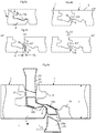
- FIG. 1 A first example of floorboards 1, 1' provided with a mechanical locking system obtainable by a method according to the invention is shown in figures 2a - 2d .
- a building panel is shown that in this example is a floorboard comprising a surface 2 attached to, or of, a core 3.
- the floorboard is provided with a locking system for vertical and horizontal locking of a first 1 and a second edge 1' of adjacent panel edges.
- the upper parts of two edges 1,1' of two joined floorboards together define a vertical plane VP.
- the vertical plane is perpendicular to a horizontal plane HP that is parallel to the panel surface.
- the locking system is configured to lock the edges 1, 1' by angling two adjacent edges relative each other.
- the locking system comprises a tongue 10 made in one piece with said core 3 that cooperates with tongue groove 9 in the adjacent edge 1' for vertical locking.
- the tongue groove 9 comprises a lower lip 9a and an upper lip 9b above the lower lip.
- the first edge 1 comprises a strip 6 made in one piece with the core 3 and provided with a locking element 8 which cooperates for horizontal locking with a downwardly open locking groove 14 formed in the second adjacent edge 1'.
- the tongue 10 is located on the first edge 1 above the strip 6 and protrudes outwardly beyond the vertical plane VP.
- Figure 2b shows that the tongue 10 and the tongue groove 9 comprise upper 12 and lower 13 cooperating vertically locking surfaces.
- the locking element 8 and the locking groove 14 comprises cooperating horizontally locking surfaces 15 that lock horizontally and prevents a horizontal separation of the adjacent edges 1, 1'.
- the geometry of an angling locking system is limited in many respects by the rotating movement that is needed to accomplish a locking.
- the locking surfaces are, during the final stage of the angling motion, rotated along circles C1, C2, which have a centre point at the vertical plane in the upper part of the joint edges.
- a tangent line defines the "free angle" A that is the angle when the edges may be locked and separated without any locking surfaces that overlap each other and prevents such locking or disconnection.
- the free angle A increases when the locking element 8 is closer to the surface and/or more distant horizontally to the vertical plane VP. This means that a low locking angle makes it possible to design compact and cost efficient locking system. However this has a negative effect on the locking strength and the final guiding into a locked position.
- Over angling with locking angles LA higher than the free angle may be used if the locking surfaces are small and the material is partly compressible.
- the horizontally locking surfaces 15 should comprise a locking angle of more than about 30 degrees in order to provide sufficient strength and guiding. Higher locking angles are even more preferable and a high quality locking system requires generally a locking angle of 45-60 degrees. Locking systems with higher locking angles that may be up to 90 degrees provides very strong locking. All such locking angles may be obtained with a method of forming a locking system according to the described invention.
- the tongue 10 and the tongue groove 9 should also be formed and adapted to the rotation during the final locking step.
- Rounded locking surfaces are optimal for a locking with angling but are in practice not suitable to use due to production tolerance.
- the ideal geometry is therefor essentially plane locking surfaces parallel with the surface that allow that the rotating tools may be displaced horizontally without any effect on the vertical position of the upper edges.
- the locking system has therefore in this example preferably a lower lip 9a located under the tongue 10 that extends beyond the upper lip 9b and that allows forming of plane vertically locking surfaces 12, 13 that are essentially parallel with the horizontal plane HP.
- the tongue 10 and the tongue groove 9 comprises preferably upper 12 and lower 13 vertically locking surfaces that are essentially parallel with the horizontal plane HP and offset horizontally such that a part of the upper vertically locking surfaces 12 are closer to the locking element 8 than the lower vertically locking surfaces 13.
- the horizontal extension TE of the tongue 10 is larger than the horizontal extension LE of the lower lip 9a extending beyond the upper lip 9b.
- the locking system may also be formed with a lower lip 9b that is not extending beyond the upper lip 9b or even with an upper lip 9b that protrudes horizontally beyond the lower lip 9a. Having the eventual extension LE of the lower lip 9b as small as possible may limit the material waste. It is preferred that the extension of the lower lip 9a does not exceed more than about 0,5 times the extension TE of the tongue 10. A small extending lower lip 9b will not create additional waste since the saw blade must generally cut at a small distance from the edge in order to allow a final machining of the edges that removes chipping caused by the saw.
- This cutting distance to the final edge is also used to machine and form "banana shaped" edges into a straight edge.
- a small extension LE of about 1 mm will therefore not increase the material waste but may be used to form locking surfaces and/or guiding surfaces in the lower lip 9a.
- a strong vertical locking force may be obtained in a wood or HDF core with vertically locking surfaces 12, 13 that comprises a horizontal extension of about 1 mm and even less for example 0,5 mm may be sufficient in some applications.
- the locking system comprises a space S between the upper part of the strip 6 and the second edge 1'. This may be used to eliminate the need for a precise positioning of the machining tools.
- the space S is preferably located vertically under the tongue 10.
- the locking system should be able to guide the edges into a correct position during installation.
- the floorboards are often somewhat curved or bended and the locking system should be able to straighten such bending and to guide the edges into a correct position.
- the tongue 10 and the groove 9 comprises preferably guiding surfaces 17a, 17b that are in contact with each other during angling when an edge portion EP of the second edge 1' is in contact with the strip 6 and/or the locking element 8 as shown in figure 2c
- the guiding surfaces 17a, 17a', 17b, 17b' are preferably inclined relative the vertical plane VP and may be located on the upper and/or lower parts of the tongue 10 and the tongue groove 9.
- the guiding surfaces may also be rounded.
- At least two cooperating guiding surfaces 17a, 17b should preferably be in contact with each other when the second edge 1' is position in an angle of about 10 - 20 degrees against the horizontal plane and with an edge portion EP in contact with the strip and/or the locking element as shown in figure 2c .
- the upper vertically locking surfaces 12 are preferably offset horizontally in relation to the lower horizontally locking surfaces 13 with a distance LD. It is preferred that this distance LD is larger than zero. LD is preferably larger than 20% of the horizontal extension TE of the tongue 10.
- the upper vertically locking surfaces 12 are preferably offset horizontally in relation to the lower horizontally locking surfaces 15 with a distance D. It is preferred that this distance D is larger than the horizontal extension TE of the tongue.
- the horizontally locking surfaces 15 are located below a horizontal strip plane HPS that intersects an upper part 6a of the strip 6.
- This upper part is preferably located essentially vertically under the outer part of the tongue 10.
- Such geometry simplifies the forming of the edges since for example only vertically and horizontally rotating tools may be used. It allows maximum materials savings as described further below.
- Figures 3a - 3f show that the locking system may more compact if the locking element 8 is moved towards the upper part of the floorboard.
- Figure 3c shows that the horizontally locking surfaces 15 may be located both below and above the horizontal strip plane HPS.
- FIG. 3e shows that the horizontally locking surfaces 15 may also be located above the horizontal strip plane HPS.
- the locking angle A is in this example about 60 degrees.
- the free angle is about 50 degrees which means that this locking system comprises an over angling of about 10 degrees.
- the strip 6 comprises a rear side 6b, which is somewhat angled upwards and where the balancing layer and/or the core has been removed. This increases the flexibility of the strip and allows a small bending during locking and unlocking. It may also be used to create a predetermined flexibility of the strip that may be used to create a pre tension inwardly and upwardly. This may be used to increase the angle of the horizontally locking surfaces and to eliminate some production tolerances.
- the floorboards may also be connected to the sub floor by nailing down and the tongue 10 provides a strong base for a nail 24.
- a nailing groove 26 may be formed on the rear side in order to prevent splitting of the rear side.
- the floorboards may have bevels 4 or a decorative groove 5 at the upper edges. It is preferred that the decorative groove 5 is formed on the second edge 1' where chipping from the saw blade is most critical.
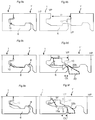
- Figures 4a - 4f describe examples of locking systems not forming part of the claimed subject-matter.
- Figure 4a shows that the locking system may be formed without a protruding lower lip and without a space between the strip 6 and the lower part of the adjacent edge.
- Figure 4c shows that vertical locking may be obtained with lower vertically locking surfaces 13 located on the lower part of the tongue 10 and on the upper part 16 of the strip 6 and the lower part of the second edge 1'.
- Figures 5a-b show that it is also possible to use only the lower vertically locking surfaces 13 and the horizontally locking surfaces 15 for the vertical locking.
- the strip may be used to create a pre tension P inwardly P1 and upwardly P2 with the inclined locking surfaces 15 at the locking element 8. This pre tension may create a pressing force P3 that presses the lower locking surface 13 together.
- the strip is slightly bended downwards in locked position. This makes it possible to eliminate the need for tight production tolerances even further. Only the position of the lower locking surfaces 13 must be accurately controlled in order to produce a floor without so called "over wood" at the upper joint edges.
- a locking angle of about 40 - 60 degrees is preferable to create such horizontal and vertical pre tension.
- the vertical pre tension may also be created by an upper part of the locking element 8a that presses against an inner part of the locking groove 14a.
- Figure 5b shows that essentially the same joint geometry may be used even if the floor thickness is increased.
- the lower part of the strip 6b may be such that the strip thickness is reduced.
- a horizontal groove may be formed in the strip under the locking element in order to increase the flexibility.
- locking systems may be partly or completely combined into alternative examples of locking systems.
- the locking systems may be used to lock long and/or short edges with an angling action.
- the locking system may also be adapted to be locked with horizontal snapping whereby the strip bends 6 backwards during the snapping action when lower guiding surfaces on the tongue and the lower lip cooperate with each other. This may for example be used to connect a long edge to a short edge or to snap long edges when angling is not possible.
- the locking system may also be connected by angling of the first edge 1 whereby the strip 6 is inserted under the lower lip.
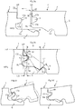
- Figures 6a - 6g show several production methods of dividing a board.
- the board is a laminate board comprising a core 3, an upper surface 2, preferably comprising a decorative layer, and a lower surface, preferably comprising a balancing layer, into a first and a second panel, with first and second adjacent edges 1,1'. Two adjacent edges 1,1' are formed comprising a locking system that locks vertically and horizontally.
- the first and the second panel may be e.g. building panels or floor panels.
- the methods may be used to divide the board into a first and a second panel.
- the first panel comprises a first edge 1 adjacent a second edge 1' of the second panel.
- the first edge comprises an extension (10,6,8) that protrudes horizontally beyond an upper part of the first edge 1.
- a first and a second vertically open grooves 19, 18, are formed in the board by for example rotating saw blades 20. The grooves are horizontally offset.
- the second vertical open groove 18 comprises an opening towards the front side of the board and the first vertical groove 19 comprises an opening towards the rear side of the board.
- the board may be divided into several panels in various ways.
- Figure 6b shows breaking or splitting that may be obtained by angling or pressing apart the edges 1, 1'.
- This method is very suitable when HDF is used as a core since the fibres are oriented horizontally and the crack is essentially horizontal.
- the same method may be used in a plywood core with different layer that may be design to create a controlled crack along one of the veneers.
- the fibre orientation is essentially oriented from one groove towards the other groove.
- the methods of dividing also comprise the step of cutting by a fixed tool, such as a carving tool(s) 22, as shown in figure 6c .
- the method comprises the step of forming a horizontally extending groove in the first vertical open groove and/or the second groove by the fixed tool (22).
- the horizontally extending groove extends from one of the first groove or the second vertically open groove toward the other of the first groove or the second vertically open groove.
- the horizontally extending groove extends under the front side of the board and/or above the rear side of board.
- FIG. 6C shows an embodiment comprising the step of forming a first horizontally extending groove, which extends from the first vertically open groove towards the second vertically open groove, and forming a second horizontally extending groove, which extends from the second vertically open groove towards the first vertically open groove.
- Embodiments may comprise the step of cutting a part of the first and/or the second vertically open groove by a saw blade before cutting a first and/or a second horizontally extending groove by a fixed tool.
- Figure 6d shows that the first vertically open groove may be formed by a rotating saw blade 20 and the second vertically open groove may be formed by a scraping or carving tool 22.
- Figure 6e shows an example, not forming part of the claimed subject-matter, that a knife 21 may be used to divide the first and second panel.
- Figures 6f and 6g shows an example, not forming part of the claimed subject-matter, including forming of the first vertically open groove and of the second vertically open groove that overlap each other.
- the second vertically open groove may be formed by a sawblade and the first vertically groove by a scraping or carving tool 22.
- the step of splitting or forming of the horizontal groove is not required in this example.
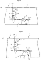
- Figure 7a and 7b shows an example, not forming part of the claimed subject-matter, where the final separation may be made with a band saw 23 that cuts the core. Such a separation gives a very controlled cut and may be used in materials that are difficult to split, cut or carve.
- Figure 7c shows an embodiment for dividing a board to a first panel (1) and a second panel 1' by a by displacing the board past a fixed tool 22, such as a carving tool.
- the board may be provided with a balancing layer and/or a decorative layer and a fixed tool makes it possible to sort and dispose into separate containers chips from the core and the balancing layer and/or the decorative layer.
- the chips are preferably removed by several compressed air nozzles.
- Adjacent edges of the first and the second panel are preferably vertically overlapping and comprise a lower protruding part at a first edge of the first panel and a lower groove at a second edge of the second pane.
- a mechanical locking system e.g. as described herein, is formed at the adjacent edges by carving.
- a locking element may be formed at the lower protruding part that is configured to cooperate with a locking groove, which may be formed at the lower groove.
- the vertically overlapping edges may reduce the waste of the board material relating to the dividing of the board and the forming the mechanical locking system.
- the method illustrated in figure 7c is preferably used for dividing MDF or HDF boards or boards comprising plastic, such as PVC.
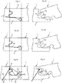
- Figure 8a show a preferred locking system, the locking system itself is not forming part of the claimed subject-matter, with a tongue 10 on the strip side 1.
- Figure 8b show that the edges 1, 1' can obtain a relative position such that the upper surfaces 2 are positioned along the same horizontal plane HP and such that an edge part EP of one of the adjacent edges is located vertically above the upper part 8a of the locking element 8 and that there is a vertically extending space S of at least about 0,5 mm between the locking element 8 and the whole adjacent edge which is located above the locking element 8.
- the space S may be smaller but this makes the final separation much more costly and complicated.
- edge geometry as shown in figure 8b makes it possible to divide the board into floor panels with a carving tool, which may have sufficient size in order to divide the board in high speed and with a sufficient accuracy and tool lifetime.
- Figure 8c show that the overlapping OL of the final machined edge portions may be even larger if the joint geometry is such that the necessary space S above the locking element 8b exists on and along the vertical plane VP. An even larger overlapping and cost saving may be reached if the space S exists when the edge part EP is located at the vertical plane VP and vertically above one of the horizontally locking surfaces 15a on the locking element 8.
- Figure 8e show that the first 19 and/or the second 18 vertically open groove may be formed by a rotating saw blade 20 and/or a carving tool 22.
- the second vertically groove 18 is formed by a rotating saw blade 20 and the first by a carving tool 22a.
- second groove (18) is made by sawing by the rotating saw blade (22), and that the first groove (19) is made before the cutting of the second groove (18) .
- the panels are finally divided by an upper and a lower carving tool 22c, 22b that are inserted in the pre formed grooves and that forms essentially horizontal grooves.
- Such non-linear separation combined with overlapping edges OL may be used to decrease material waste W in all types of locking systems.
- the material waste W in a laminate floor may be less than the floor thickness T. It is possible to reduce the waste to about 5 mm and less in a laminate floor with a thickness of about 6 -12 mm.
- the board may be arranged on a carrier, such as a conveyor belt/chain, preferably provided with a pushing device, such as a cam or ridge (not shown).
- a pushing device such as a cam or ridge (not shown).
- the decorative surface of the board may be arranged against the carrier and facing downwards (not shown).
- the pushing device may be used to overcome the rather high cutting forces that have to be overcome in order to create a groove with non-rotating carving tools.
- Figure 9a - 9f show that considerable material waste W savings may be reached with a nonlinear panel separation and with overlapping edges OL even if the tongue 10 is formed on the second edge 1' as in conventional locking systems as shown in figures 9a-9b.
- Figure 9b shows that the waste W may be decreased with two offset vertical grooves and with a small carving.
- Figure 9c shows that it is possible to modify the locking system such that it may be compatible with the old locking system and that an increased overlapping of the edges may be obtained as shown in figure 9d .
- a part of the lower part of the tongue 10 and the upper outer part of the locking element 8 may be removed by a small rotating milling tool, as an example not forming part of the claimed subject-matter, that may be angled or by a carving tool, according to the invention, such that a space S may be created when the edges 1, 1' are in an overlapped position as described above. It is preferred that the space S is larger above an outer part of the locking element than above the top of the locking element such that a strong and rather large carving tool edge 22b may be used to divide the panels.
- Figure 9e-9f show that further cost savings and a larger overlapping may be reached if the tongue 10 is moved upwards.
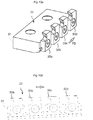
- Figure 10a shows a carving tool with four carving teeth 30a-30d.
- the teeth are connected to a tool body 31.
- Each carving tooth is fixed in an adjustable tool holder.
- Several carving teeth may be of the same length and the cutting depth may be adjusted by the adjustable tool holder.
- Figure 10b shows that the tool body may be slightly inclined such that each tooth carves a depth of for example 0,2 mm when the panel is displaced in the feeding direction against the fixed carving tool.
- Each tooth may be designed to carve a distance of for example 0,2 -0,6 mm in a wood based core.
- HDF is especially suitable to be formed with carving.
- Figure 11a shows how the first tooth 30a cuts the first cut under the backing laminate 11.
- the tooth edges comprise 3 cutting edges that formed the groove bottom 31a and two sidewalls 31b, 31c. It is preferred that the teeth have gradually smaller width along the feeding direction. Slightly V shaped teeth may be used to provide a more accurate cut with reduced chipping of the laminate. This reduces tool wear and the heat that may be created at high feeding speeds.
- Figure 11b shows carving of an essentially horizontal groove that provides the final separation.
- the groove angle in the final groove may vary from zero to 45 degrees against the horizontal plane HP.
- Embodiments of the invention are especially suitable to be used in solid wood floor where the material cost is high and where a protruding tongue creates a high waste cost.
- a floor comprising small individual rectangular small size parquet strips with width and length of 10*50 cm or smaller may be produced in a cost very efficient way with considerably lower waste.
- Embodiments of the invention are also suitable for panels, such as building panels and floor panels, with a digitally printed surface.
- the advantage is that it's not required to adjust the printed paper pattern on the board to the size of the panels, produced by the divided board, by an adjustment of the printing cylinder.
- the forming of the vertical grooves may be formed with thinner tools since the digitally printed surface layer is normally easy to cut.
- Panels, such as building panels and floor panels may also be formed without a decorative surface.
- a decorative surface and a protective layer may be applied by for example digital printing after the locking system is already formed. This method reduces the surface waste to a minimum.
- Mechanical locking systems may be formed by rotating tools that generally have a diameter of about 20 cm or more.
- Rotating tool configurations are driven by tool motors which is a big cost of the total investment in a production line, they are also energy consuming, have a complicated electrical control system, and require a lot of maintenance.
- Rotating tools produce a lot of dust that have to be extracted.
- the dust comprises of a mixture of removed ships and dust.
- a disadvantage of even a sophisticated dust extraction system for rotating tool configurations, is that a fraction of dust and chips that goes in to the transport system and causes wear that effects the precision of the transport system in a negative way. All such problems may be reduced if rotating tools are replaced by carving tools.
- Carving prior to the final separation may according to embodiments of the invention form several parts of the locking system or even the whole locking system. Scraping of the top edges with V shaped carving tools may provide a very precise and smooth edge.
- the locking groove 14 may in a subsequent production step be used to guide the panels in correct position and this may be used to decrease the overlapping OL further and to save even more material.
Description
- Embodiments of the invention generally relate to the field of mechanical locking systems for building panels, especially floorboards. Embodiments of the invention relate to methods for making floorboards with such locking systems.
- Embodiments of the present invention are particularly suitable for use in floating floors, which are formed of floorboards which are joined mechanically with a locking system made in one piece with the core and are made up of one or more upper layers of veneer, decorative laminate or decorative plastic material, an intermediate core of wood-fibre-based material or plastic material and preferably a lower balancing layer on the rear side of the core, and are manufactured by sawing large boards into several panels. The following description of known technique, problems of known systems and objects and features of embodiments of the invention will therefore, as a non-restrictive example, be aimed above all at this field of application and in particular to laminate flooring formed as rectangular floorboards intended to be mechanically joined on both long sides and short sides. However, it should be emphasised that the invention may be used in any floorboards or building panels, which are intended to be locked together on two adjacent edges horizontally and vertically with a mechanical locking system that allows locking, preferably by an angling motion. Embodiments of the invention may thus also be applicable to, for instance, solid wooden floors, parquet floors with a core of wood lamellas or wood-fibre-based material and the like which are made as separate floor panels, floors with a printed and preferably also varnished surface and the like. Embodiments of the invention may also be used for joining building panels, for instance, of wall panels and furniture components.
- Laminate flooring usually comprise of a core of 6-11 mm fibreboard, a 0.1-0.8 mm thick upper decorative surface layer of laminate and a 0.1-0.6 mm thick lower balancing layer of laminate, plastic, paper or like material. The surface layer provides appearance and durability to the floorboards. The core provides stability, and the balancing layer keeps the board plane after pressing and when the relative humidity (RH) varies during the year. The floorboards are laid floating, i.e. without gluing, on an existing subfloor. Traditional hard floorboards of this type were usually joined by means of glued tongue-and-groove joints. However the majority of all laminate floorboards are presently joined mechanically by means of so-called mechanical locking systems. These systems comprise locking means, which lock the boards horizontally and vertically. The mechanical locking systems are usually formed by machining of the core. Alternatively, parts of the locking system may be formed of separate materials, for example aluminium or plastic, which are factory integrated with the floorboard.
- The main advantages of floating floors with mechanical locking systems are that they can easily and quickly be laid by various combinations of angling and snapping. They may also easily be taken up again and used once more at a different location.
- The most common core material is a fibreboard with high density and good stability usually called HDF - High Density Fibreboard. Sometimes also MDF - Medium Density Fibreboard - is used as core.
- A laminate board which comprises a surface of melamine impregnated decorative paper, plastic, wood, veneer, cork and the like are made by the surface layer and preferably a balancing layer being applied to a core material that in addition to HDF may be made of plywood, chipboard, plastic, and various composite materials. Recently a new board have been developed where a powder, comprising fibres, binders, wear resistant particles and colour pigment, is scattered on a core material and cured by heat and pressure to a solid paper free surface.
- As a rule, the above methods result in a laminate board, which is divided by sawing into several panels, which are then machined to provide them with a mechanical locking system at the edges. A laminate board of the size of a panel, which is not necessary to divide, may be produced by the above method. Manufacture of individual floor panels usually takes place when the panels have a surface layer of wood or veneer.
- Floorboard with mechanical locking systems may also be produced from solid materials such as solid wood.
- In all cases, the above-mentioned floor panels are individually machined along their edges to floorboards. The machining of the edges is carried out in advanced milling machines where the floor panel is exactly positioned between one or more chains and belts, so that the floor panel may be moved at high speed and with great accuracy past a number of milling motors, which are provided with rotating diamond cutting tools or metal cutting tools and which machine the edge of the floor panel. By using several milling motors operating at different angles, advanced joint geometries may be formed at speeds exceeding 200 m/min and with an accuracy of about ±0.05 mm. The accuracy in the vertical direction is generally better than in the horizontal direction since it is difficult to avoid so called swimming which occurs when panels move horizontally in relation to the chain/belt during milling.
- In the following text, the visible surface of the installed panel, such as a floorboard, is called "front side", while the opposite side of the floorboard, facing the subfloor, is called "rear side".
- By "horizontal plane" is meant a plane, which extends parallel to the front side. Immediately juxtaposed upper parts of two neighbouring joint edges of two joined panels together define a "vertical plane" perpendicular to the horizontal plane.
- The outer parts of the floorboard at the edge of the floorboard between the front side and the rear side are called "joint edge". As a rule, the joint edge has several "joint surfaces" which may be vertical, horizontal, angled, rounded, beveled, etc.
- By "locking system" are meant coacting connecting means, which connect the panels vertically and/or horizontally. By "mechanical locking system" is meant that joining may take place without glue.
- By "angling" is meant a connection that occurs by a turning motion, during which an angular change occurs between two parts that are being connected, or disconnected. When angling relates to connection of two floorboards, the angular motion generally takes place with the upper parts of the joint edges at least partly being in contact with each other, during at least part of the motion.
- By "up or upward" means toward the front side and by "down or downward" means toward the rear side. By "inwardly" is meant towards the centre of the panel and by "outwardly" means in the opposite direction.
- By "carving" is meant a method to form a groove or a protrusion on an edge of a panel by carving a part of the edge to its final shape by one or several carving tool configurations comprising several non-rotating and fixed chip-removing surfaces located along the feeding direction.
- With a view to facilitating the understanding of embodiments of the present invention, known mechanical locking system will now be described with reference to
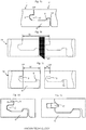
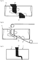
Figs 1a-1e . - As shown in
figure 1a the floorboards have atongue 10 and agroove 9 that locks the edges in a vertical direction. Astrip 6, which extends along afirst edge 1, protrudes from the edge and has alocking element 8 that cooperates with alocking groove 14 in the adjacent second edge 1' and locks the edges horizontally. - It is evident from this figure and
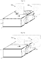
figure 1b , that since the mechanical locking systems have parts, such as thetongue 10 and thestrip 6, that project beyond the upper joint edges, expensive waste W is created when thelarge board 1b is cut by asawblade 20 into several floor panels and when the locking system is formed. - Even when individual floor panels are produced, for example floors of solid wood, as shown in
figure 1c , considerable waste (W) is caused by forming thestrip 6 and thetongue 10. - These systems and the manufacturing methods suffer from a number of drawbacks, which are above all related to cost and function.
- The waste is mainly related to the long edge locking system, which generally is installed by angling. The total waste may be about 10 mm or more or about 5% in floorboards that have a width of about 200 mm. The waste in narrow floorboards with a width of for example 100 mm may be about 10%.
- To counteract these problems, different methods are used. The most important method is to limit the extent of the projecting parts. This usually results in lower locking strength and difficulties in laying or detaching the floorboards.
- Another method is to use separate materials, for example aluminium or plastic, to form the strip or the tongue. Such materials are generally not cost efficient in low cost floors with a surface layer and a core made of very cost efficient materials such as impregnated paper and HDF respectively.
- It is known that a locking system may be formed with overlapping edges A, B and a lower tongue C as shown in
figure 1d (WO 2005/068747 Välinge Innovation AB). Such locking system will not reduce the waste. The overlapping edge or small tongue A is mainly used to facilitate horizontal displacement between the edges.Figure 1e shows a known locking system (WO 2006/043893 Välinge Innovation AB) that has a separateflexible tongue 10 attached above thestrip 6 and that is mainly intended to lock the short edges with vertical folding or vertical snapping. - The disclosure "VA073a Zip Loc", IP.com Journal, with disclosure number IPCOM000210869D and publication date 2011-Sep-13, is considered to be the prior art document closest to the subject-matter of
claim 1 and it describes that waste created when forming a locking system may be reduced by cutting individual panels vertically and horizontally. A cutting groove may be formed with knifes or rotating cutting tools and the panels may thereafter be separated by a knife that cuts essentially horizontally and a knife that cuts essentially vertically. - An object of embodiments of the invention is to provide a rational and cost-efficient manufacturing method to divide a board into floorboards which are in a second production step machined to provide them with a mechanical locking system.
- The above objects may be achieved wholly or partly by production methods according to embodiments of the invention.
- A first aspect of the invention is a method for dividing a board into a first panel and a second panel according to
claim 1. - The method comprises the step of forming a first vertically open groove, through a rear side of the board and an offset second vertically open groove, through a front side of the board.
- A fixed tool or a saw blade may form the first vertically open groove.
- The second vertically open groove may be formed by a fixed tool or a saw blade. The second vertically open groove is preferably made by sawing in order to obtain a smooth edge with less chipping at an edge of the front side, since the edge may be visible when the panel is installed.
- The method comprises the step of forming, by a fixed tool, a first horizontally extending groove that extends horizontally under the front side and/or rear side of the board.
- The first horizontally extending groove extends from the second groove towards the first groove, or from the first groove towards the second groove.
- The first horizontally extending groove may connect the first vertically open groove and the second vertically open groove.
- The method may comprise the step of forming, by a fixed tool, a second horizontally extending groove that extends horizontally under the front side and/or rear side of the board, wherein the second horizontally extending groove extends from the second vertically open groove towards the first vertically open groove and the first horizontally extending groove extends from the first vertically open groove towards the second vertically open groove.
- The first horizontally extending grooves may be connected with the second horizontally extending grooves.
- The forming of the second vertically open groove may be made by sawing by a rotating saw blade.
- The forming of the first groove is preferably made before the cutting of the second groove and wherein the first groove is made by a fixed tool. The step of displacing the board past the fixed tool, is preferably made before the sawing step, since that makes it easier to absorb the forces created by the fixed tool when forming the groove.
- The method may comprise the step of method arranging the board on a carrier, such as a conveyor belt/chain, preferably provided with a pushing device, such as a cam or ridge. The pushing device, such as a cam or ridge, increases the force the building element may be pushed towards the fixed tool.
- The front side of the board may be arranged against the carrier and facing downwards. The front side is preferably arranged facing downward and supported by a carrier, such as a conveyor belt/chain. If the steps above forms a part of a locking system that increase the production tolerances and critical locking surfaces may be produced with high tolerances.
- The fixed tool comprises several carving teeth, arranged for forming at different vertical and/or horizontal positions.
- The method comprises the step of removing the chips created by the fixed tool, preferably by compressed air, preferably by a compressed air nozzle, and preferably collected by a suction device.
- The board may be a wood based board, a laminated board, such as a floor element comprising a core of HDF or MDF, a decorative layer and a balancing layer, a plywood board, or a board comprising a plastic core and preferably a decorative layer.
- The laminated board may comprises a core provided with a decorative surface layer and a balancing layer.
- The method comprises the step of removing the chips created by the forming, preferably by several compressed air nozzles, and preferably sorting and disposing into separate containers the chips from the core and the balancing layer and/or the decorative layer.
- A second aspect of the invention is method of forming a mechanical locking system for locking of a first and a second panel, wherein the method comprises the steps:
- dividing a board into a first and a second panel according to the methods described herein and thereby forming a lower protruding part at a first edge of the first panel and a lower groove at a second edge of the second panel;
- forming a locking element at the lower protruding part;
- and forming a locking groove at the lower groove.
- A third aspect, not forming part of the claimed subject-matter, are building panels, each comprising an upper surface and a core, provided with a locking system for vertical and horizontal locking of a first edge of a first building panel to an adjacent second edge of a second building panel. The upper parts of the first and the second edge together define in a locked position a vertical plane, which perpendicular to a horizontal plane, which is parallel to the upper surface of the first and the second building panel. The locking system is configured to enable assembling of the first and the second edge by angling the first and the second building panel relative each other. The locking system comprises a tongue, made in one piece with said core, and a tongue groove configured to cooperate for vertical locking, and a strip at the first edge, made in one piece with the core, which is provided with a locking element, and configured to cooperate for horizontal locking with a downwardly open locking groove formed in the second edge. The first and the second building panel (may obtain a relative position with a distance between the first and the second edge, in said position the upper surface of the first and the second building panel (1, 1') are in the same horizontal plane and an edge part of the second edge is located vertically above the upper part of the locking element and that there is a vertically extending space S of at least about 0,5 mm between the locking element and all parts of the second edge which is located above the locking element.
- The edge part may be located at the vertical plane.
- The locking element may comprises a locking surface that cooperates with a locking surface at the locking groove for horizontal locking and wherein the edge part is located vertically above the locking surface of the locking element.
- The space may be larger than 0,6 mm.
- The space may be equal or larger above the outer part of the locking element than above the upper part of the locking element.
- The edge portion may comprise a lower part that is inclined downwards and inwardly.
- The edge part may comprise a lower part of the tongue.
- The building panel may be a floorboard.
- A fourth aspect, not forming part of the claimed subject-matter, is a method to divide a board, comprising a core and a surface, wherein the method comprises the step of:
- forming in the core a first and a second essentially vertical grooves, which are horizontally offset, wherein the first groove comprises an opening towards the front side and the second groove comprises an opening towards the rear side of the board;
- dividing the board into a first floor panel with a first edge and a second floor panel with a second edge, wherein the first edge is adjacent the second edge; and
- forming a locking system on the first and second edge comprising a strip, a locking element and a locking groove for horizontal locking and a tongue and a tongue groove for vertical locking.
- The second groove may be formed by a carving tool.
- The board may be divided by a carving tool.
- The board may be divided by carving tools that are inserted into the first and the second grooves.
- The carving tool that divides the panels may cut an essentially horizontally extending groove that comprises an angle of less than 45 degrees against the horizontal plane HP.
- The first or the second groove may be formed by a carving tool with carving teeth that are displaced horizontally with a distance of at least about 0,2 mm.
- A fifth aspect, not forming part of the claimed subject-matter, is building panels comprising a surface and a core, provided with a locking system for vertical and horizontal locking of a first edge of a first building panel to an adjacent second edge of a second building panel. The upper parts of the first and the second edge, in a locked position, together define a vertical plane perpendicular to a horizontal plane, which is parallel to the surface. The locking system is configured to enable assembling of the first and the second edge by angling the first and the second building panel relative each other. The locking system comprises a tongue, made in one piece with said core, and a tongue groove configured to cooperate for vertical locking. The first edge comprises a strip, made in one piece with the core, which is provided with a locking element, which is configured to cooperate for horizontal locking with a downwardly open locking groove formed in the second edge. The tongue, which is provided on the first edge, cooperates with a lower lip of the tongue groove, which is provided at the second edge and comprises lower vertically locking surfaces. The locking element and the locking groove cooperate at horizontally locking surfaces. The tongue protrudes outwardly beyond the vertical plane and the tongue groove comprises an upper lip. The horizontal extension of the lower lip, in relation to the upper lip, is smaller than the horizontal extension of the tongue.
- The building panels may comprise cooperating horizontally locking surfaces that lock the edges both horizontally and vertically with horizontal and vertical pre tension.
- The building panels may comprise a tongue that cooperates with the upper lip at upper vertically locking surfaces.
- The tongue and the tongue groove may comprise upper and lower vertically locking surfaces that are essentially parallel with the horizontal plane and offset horizontally such that a part of the upper vertically locking surfaces are horizontally closer to the locking element than the lower vertically locking surfaces.
- The lower lip may protrude beyond the upper lip and the vertical plane.
- The horizontal extension of the tongue may be at least about twice as large than the horizontal extension of the lower lip.
- The tongue and the tongue groove may comprise guiding surfaces that are configured to be in contact with each other, during the assembling by angling, when an edge part of the second edge is in contact with the strip and/or the locking element.
- The guiding surfaces may be inclined relative the vertical plane and located on the upper and/or lower parts of the tongue and the tongue groove.
- The horizontal locking surfaces may be located below a horizontal strip plane that intersects an upper part of the strip, which is located essentially vertically under the outer part of the tongue.
- The horizontally locking surfaces may be located both below and above the horizontal strip plane.
- The horizontal locking surfaces may be located above the horizontal strip plane.
- The locking system may comprise a space between the upper part of the strip and an edge portion of the second panel located essentially under the tongue.
- The upper vertically locking surfaces may be offset horizontally in relation to the horizontally locking surfaces.
- The vertically and horizontally locking surfaces may be offset horizontally with a horizontal distance that is larger than the horizontal extension of the tongue.
- The core may comprise HDF, particleboard plastic or plywood.
- The horizontally locking surfaces may have a locking angle of about 40 - 60 degrees against the horizontal plane.
- A sixth aspect, not forming part of the claimed subject-matter, is a method to divide a board, comprising a core and a surface, wherein the method comprises the step of:
- forming in the core a first and a second essentially vertical groove, which are horizontally offset, wherein the first groove comprises an opening towards the front side and the second groove comprises an opening towards the rear side of the board;
- dividing the board into a first floor panel with a first edge and a second floor panel with a second edge, wherein the first edge is adjacent the second edge; and
- forming a locking strip and a tongue for vertically and horizontally locking of the first and the second floor panel, wherein the locking strip and the tongue protrude horizontally beyond an upper part of the first edge of the first panel.
- The board may be divided by knives.
- The board may be divided by scraping of the core.
- The board may comprise a plywood core, which is divided at least partly along one of the veneers.
- The board may comprise a plywood core, which is divided essentially along one of the veneers, which comprises a fibre orientation essentially oriented from one groove towards the other groove.
- The first or the second groove may be formed by a rotating tool and the other groove by carving or scraping.
- The second groove may be formed by carving or scraping.
- The first and the second grooves may be formed by carving or scraping.
- A seventh aspect, not forming part of the claimed subject-matter, is a building panel, such as a floor panel, according to the third or fifth aspect and produced according to the first, the second, the fourth or the sixth aspect.
- A locking system that comprises a tongue on the same edges as the protruding strip and that allows a separation of board by two offset cutting grooves provides a considerable material saving. The joint geometry as describes above provides precise guiding of the edges during locking and a strong lock when the edges are angled into a locked position.
- The present invention will by way of example be described in more detail with reference to the appended schematic drawings, which shows embodiments of the present inventions and examples not forming part of the claimed subject-matter.
- Figs 1a-e
- illustrate known technology.
- Figs 2a-d
- illustrate a locking system obtainable by a method according to an embodiment of the invention.
- Figs 3a-f
- show alternative locking systems obtainable by a method according to embodiments of the invention.
- Figs 4a-f
- show alternative locking systems obtainable by a method according to embodiments of the invention.
- Figs 5a-b
- show a preferred locking system obtainable by a method according to an embodiment.
- Figs 6a-6g
- show separation of a board into several floor panels according to an embodiment of the invention.
- Figs 7a-b
- show separation with a band saw.
- Figs 7c
- shows a method to divide a board into two panels by a fixed tool, a carving tool, according to an embodiment of the invention.
- Figs 8a-e
- show a locking system, not forming part of the claimed subject-matter, and a method to divide the panels with carving tools according to embodiments of the invention.
- Figs 9a-f
- show how conventional locking systems may be adjusted and divided according to embodiments of the invention.
- Figs 10a-b
- show a carving tool, the tool being used in a method according to an embodiment of the invention.
- Figs 11a-b
- show carving of horizontal and vertical grooves according to embodiments of the invention.
- A first example of
floorboards 1, 1' provided with a mechanical locking system obtainable by a method according to the invention is shown infigures 2a - 2d . - A building panel is shown that in this example is a floorboard comprising a
surface 2 attached to, or of, acore 3. The floorboard is provided with a locking system for vertical and horizontal locking of a first 1 and a second edge 1' of adjacent panel edges. The upper parts of twoedges 1,1' of two joined floorboards together define a vertical plane VP. The vertical plane is perpendicular to a horizontal plane HP that is parallel to the panel surface. The locking system is configured to lock theedges 1, 1' by angling two adjacent edges relative each other. The locking system comprises atongue 10 made in one piece with saidcore 3 that cooperates withtongue groove 9 in the adjacent edge 1' for vertical locking. Thetongue groove 9 comprises alower lip 9a and anupper lip 9b above the lower lip. Thefirst edge 1 comprises astrip 6 made in one piece with thecore 3 and provided with alocking element 8 which cooperates for horizontal locking with a downwardlyopen locking groove 14 formed in the second adjacent edge 1'. Thetongue 10 is located on thefirst edge 1 above thestrip 6 and protrudes outwardly beyond the vertical plane VP.Figure 2b shows that thetongue 10 and thetongue groove 9 comprise upper 12 and lower 13 cooperating vertically locking surfaces. The lockingelement 8 and the lockinggroove 14 comprises cooperating horizontally lockingsurfaces 15 that lock horizontally and prevents a horizontal separation of theadjacent edges 1, 1'. - The geometry of an angling locking system is limited in many respects by the rotating movement that is needed to accomplish a locking. The locking surfaces are, during the final stage of the angling motion, rotated along circles C1, C2, which have a centre point at the vertical plane in the upper part of the joint edges. A tangent line defines the "free angle" A that is the angle when the edges may be locked and separated without any locking surfaces that overlap each other and prevents such locking or disconnection. The free angle A increases when the locking
element 8 is closer to the surface and/or more distant horizontally to the vertical plane VP. This means that a low locking angle makes it possible to design compact and cost efficient locking system. However this has a negative effect on the locking strength and the final guiding into a locked position. Over angling with locking angles LA higher than the free angle may be used if the locking surfaces are small and the material is partly compressible. Generally the horizontally lockingsurfaces 15 should comprise a locking angle of more than about 30 degrees in order to provide sufficient strength and guiding. Higher locking angles are even more preferable and a high quality locking system requires generally a locking angle of 45-60 degrees. Locking systems with higher locking angles that may be up to 90 degrees provides very strong locking. All such locking angles may be obtained with a method of forming a locking system according to the described invention. - The
tongue 10 and thetongue groove 9 should also be formed and adapted to the rotation during the final locking step. Rounded locking surfaces are optimal for a locking with angling but are in practice not suitable to use due to production tolerance. The ideal geometry is therefor essentially plane locking surfaces parallel with the surface that allow that the rotating tools may be displaced horizontally without any effect on the vertical position of the upper edges. The locking system has therefore in this example preferably alower lip 9a located under thetongue 10 that extends beyond theupper lip 9b and that allows forming of plane vertically lockingsurfaces tongue 10 and thetongue groove 9 comprises preferably upper 12 and lower 13 vertically locking surfaces that are essentially parallel with the horizontal plane HP and offset horizontally such that a part of the upper vertically lockingsurfaces 12 are closer to thelocking element 8 than the lower vertically locking surfaces 13. - The horizontal extension TE of the
tongue 10 is larger than the horizontal extension LE of thelower lip 9a extending beyond theupper lip 9b. The locking system may also be formed with alower lip 9b that is not extending beyond theupper lip 9b or even with anupper lip 9b that protrudes horizontally beyond thelower lip 9a. Having the eventual extension LE of thelower lip 9b as small as possible may limit the material waste. It is preferred that the extension of thelower lip 9a does not exceed more than about 0,5 times the extension TE of thetongue 10. A small extendinglower lip 9b will not create additional waste since the saw blade must generally cut at a small distance from the edge in order to allow a final machining of the edges that removes chipping caused by the saw. This cutting distance to the final edge is also used to machine and form "banana shaped" edges into a straight edge. A small extension LE of about 1 mm will therefore not increase the material waste but may be used to form locking surfaces and/or guiding surfaces in thelower lip 9a. A strong vertical locking force may be obtained in a wood or HDF core with vertically lockingsurfaces - The locking system comprises a space S between the upper part of the
strip 6 and the second edge 1'. This may be used to eliminate the need for a precise positioning of the machining tools. The space S is preferably located vertically under thetongue 10. - The locking system should be able to guide the edges into a correct position during installation. The floorboards are often somewhat curved or bended and the locking system should be able to straighten such bending and to guide the edges into a correct position.
- The
tongue 10 and thegroove 9 comprises preferably guidingsurfaces strip 6 and/or thelocking element 8 as shown infigure 2c - The guiding surfaces 17a, 17a', 17b, 17b' are preferably inclined relative the vertical plane VP and may be located on the upper and/or lower parts of the
tongue 10 and thetongue groove 9. The guiding surfaces may also be rounded. At least two cooperating guidingsurfaces figure 2c . - The upper vertically locking
surfaces 12 are preferably offset horizontally in relation to the lower horizontally lockingsurfaces 13 with a distance LD. It is preferred that this distance LD is larger than zero. LD is preferably larger than 20% of the horizontal extension TE of thetongue 10. - The upper vertically locking
surfaces 12 are preferably offset horizontally in relation to the lower horizontally lockingsurfaces 15 with a distance D. It is preferred that this distance D is larger than the horizontal extension TE of the tongue. - In this preferred example the horizontally locking
surfaces 15 are located below a horizontal strip plane HPS that intersects anupper part 6a of thestrip 6. This upper part is preferably located essentially vertically under the outer part of thetongue 10. Such geometry simplifies the forming of the edges since for example only vertically and horizontally rotating tools may be used. It allows maximum materials savings as described further below. -
Figures 3a - 3f show that the locking system may more compact if thelocking element 8 is moved towards the upper part of the floorboard. -
Figure 3c shows that the horizontally lockingsurfaces 15 may be located both below and above the horizontal strip plane HPS. -
Figure 3e shows that the horizontally lockingsurfaces 15 may also be located above the horizontal strip plane HPS. The locking angle A is in this example about 60 degrees. The free angle is about 50 degrees which means that this locking system comprises an over angling of about 10 degrees. Thestrip 6 comprises arear side 6b, which is somewhat angled upwards and where the balancing layer and/or the core has been removed. This increases the flexibility of the strip and allows a small bending during locking and unlocking. It may also be used to create a predetermined flexibility of the strip that may be used to create a pre tension inwardly and upwardly. This may be used to increase the angle of the horizontally locking surfaces and to eliminate some production tolerances. The floorboards may also be connected to the sub floor by nailing down and thetongue 10 provides a strong base for anail 24. A nailinggroove 26 may be formed on the rear side in order to prevent splitting of the rear side. - The floorboards may have
bevels 4 or adecorative groove 5 at the upper edges. It is preferred that thedecorative groove 5 is formed on the second edge 1' where chipping from the saw blade is most critical. -
Figures 4a - 4f describe examples of locking systems not forming part of the claimed subject-matter.Figure 4a shows that the locking system may be formed without a protruding lower lip and without a space between thestrip 6 and the lower part of the adjacent edge.Figure 4c shows that vertical locking may be obtained with lower vertically lockingsurfaces 13 located on the lower part of thetongue 10 and on theupper part 16 of thestrip 6 and the lower part of the second edge 1'. -
Figures 5a-b show that it is also possible to use only the lower vertically lockingsurfaces 13 and the horizontally lockingsurfaces 15 for the vertical locking. There may be a space S over thetongue 10 and between the upper part of thestrip 6 and the lower part of the second edge 1'. The strip may be used to create a pre tension P inwardly P1 and upwardly P2 with the inclined locking surfaces 15 at thelocking element 8. This pre tension may create a pressing force P3 that presses thelower locking surface 13 together. The strip is slightly bended downwards in locked position. This makes it possible to eliminate the need for tight production tolerances even further. Only the position of the lower locking surfaces 13 must be accurately controlled in order to produce a floor without so called "over wood" at the upper joint edges. - A locking angle of about 40 - 60 degrees is preferable to create such horizontal and vertical pre tension. The vertical pre tension may also be created by an upper part of the
locking element 8a that presses against an inner part of the lockinggroove 14a. -
Figure 5b shows that essentially the same joint geometry may be used even if the floor thickness is increased. The lower part of thestrip 6b may be such that the strip thickness is reduced. Alternatively a horizontal groove may be formed in the strip under the locking element in order to increase the flexibility. - All described examples of locking systems, not forming part of the claimed subject-matter, may be partly or completely combined into alternative examples of locking systems. The locking systems may be used to lock long and/or short edges with an angling action. The locking system may also be adapted to be locked with horizontal snapping whereby the strip bends 6 backwards during the snapping action when lower guiding surfaces on the tongue and the lower lip cooperate with each other. This may for example be used to connect a long edge to a short edge or to snap long edges when angling is not possible.
- The locking system may also be connected by angling of the
first edge 1 whereby thestrip 6 is inserted under the lower lip. -
Figures 6a - 6g show several production methods of dividing a board. The board is a laminate board comprising acore 3, anupper surface 2, preferably comprising a decorative layer, and a lower surface, preferably comprising a balancing layer, into a first and a second panel, with first and secondadjacent edges 1,1'. Twoadjacent edges 1,1' are formed comprising a locking system that locks vertically and horizontally. The first and the second panel may be e.g. building panels or floor panels. - The methods may be used to divide the board into a first and a second panel. The first panel comprises a
first edge 1 adjacent a second edge 1' of the second panel. The first edge comprises an extension (10,6,8) that protrudes horizontally beyond an upper part of thefirst edge 1. A first and a second verticallyopen grooves saw blades 20. The grooves are horizontally offset. - The second vertical
open groove 18 comprises an opening towards the front side of the board and the firstvertical groove 19 comprises an opening towards the rear side of the board. The board may be divided into several panels in various ways. -
Figure 6b shows breaking or splitting that may be obtained by angling or pressing apart theedges 1, 1'. This method, not forming part of the claimed subject-matter, is very suitable when HDF is used as a core since the fibres are oriented horizontally and the crack is essentially horizontal. The same method may be used in a plywood core with different layer that may be design to create a controlled crack along one of the veneers. Preferably the fibre orientation is essentially oriented from one groove towards the other groove. - The methods of dividing also comprise the step of cutting by a fixed tool, such as a carving tool(s) 22, as shown in
figure 6c . - According to the invention, the method comprises the step of forming a horizontally extending groove in the first vertical open groove and/or the second groove by the fixed tool (22). The horizontally extending groove extends from one of the first groove or the second vertically open groove toward the other of the first groove or the second vertically open groove. The horizontally extending groove extends under the front side of the board and/or above the rear side of board.
FIG. 6C shows an embodiment comprising the step of forming a first horizontally extending groove, which extends from the first vertically open groove towards the second vertically open groove, and forming a second horizontally extending groove, which extends from the second vertically open groove towards the first vertically open groove. Embodiments may comprise the step of cutting a part of the first and/or the second vertically open groove by a saw blade before cutting a first and/or a second horizontally extending groove by a fixed tool. -
Figure 6d shows that the first vertically open groove may be formed by a rotatingsaw blade 20 and the second vertically open groove may be formed by a scraping or carvingtool 22.Figure 6e shows an example, not forming part of the claimed subject-matter, that aknife 21 may be used to divide the first and second panel. -
Figures 6f and 6g shows an example, not forming part of the claimed subject-matter, including forming of the first vertically open groove and of the second vertically open groove that overlap each other. The second vertically open groove may be formed by a sawblade and the first vertically groove by a scraping or carvingtool 22. The step of splitting or forming of the horizontal groove is not required in this example. -
Figure 7a and 7b shows an example, not forming part of the claimed subject-matter, where the final separation may be made with aband saw 23 that cuts the core. Such a separation gives a very controlled cut and may be used in materials that are difficult to split, cut or carve. -
Figure 7c shows an embodiment for dividing a board to a first panel (1) and a second panel 1' by a by displacing the board past a fixedtool 22, such as a carving tool. The board may be provided with a balancing layer and/or a decorative layer and a fixed tool makes it possible to sort and dispose into separate containers chips from the core and the balancing layer and/or the decorative layer. The chips are preferably removed by several compressed air nozzles. Adjacent edges of the first and the second panel are preferably vertically overlapping and comprise a lower protruding part at a first edge of the first panel and a lower groove at a second edge of the second pane. A mechanical locking system, e.g. as described herein, is formed at the adjacent edges by carving. A locking element may be formed at the lower protruding part that is configured to cooperate with a locking groove, which may be formed at the lower groove. The vertically overlapping edges may reduce the waste of the board material relating to the dividing of the board and the forming the mechanical locking system. The method illustrated infigure 7c is preferably used for dividing MDF or HDF boards or boards comprising plastic, such as PVC. -
Figure 8a show a preferred locking system, the locking system itself is not forming part of the claimed subject-matter, with atongue 10 on thestrip side 1.Figure 8b show that theedges 1, 1' can obtain a relative position such that theupper surfaces 2 are positioned along the same horizontal plane HP and such that an edge part EP of one of the adjacent edges is located vertically above theupper part 8a of thelocking element 8 and that there is a vertically extending space S of at least about 0,5 mm between the lockingelement 8 and the whole adjacent edge which is located above the lockingelement 8. The space S may be smaller but this makes the final separation much more costly and complicated. - Such edge geometry as shown in
figure 8b makes it possible to divide the board into floor panels with a carving tool, which may have sufficient size in order to divide the board in high speed and with a sufficient accuracy and tool lifetime.Figure 8c show that the overlapping OL of the final machined edge portions may be even larger if the joint geometry is such that the necessary space S above the locking element 8b exists on and along the vertical plane VP. An even larger overlapping and cost saving may be reached if the space S exists when the edge part EP is located at the vertical plane VP and vertically above one of the horizontally lockingsurfaces 15a on thelocking element 8. -
Figure 8e show that the first 19 and/or the second 18 vertically open groove may be formed by a rotatingsaw blade 20 and/or acarving tool 22. In this preferred embodiment the second vertically groove 18 is formed by a rotatingsaw blade 20 and the first by acarving tool 22a. - It is preferred that second groove (18) is made by sawing by the rotating saw blade (22), and that the first groove (19) is made before the cutting of the second groove (18) .
- The panels are finally divided by an upper and a
lower carving tool - Such non-linear separation combined with overlapping edges OL may be used to decrease material waste W in all types of locking systems. The material waste W in a laminate floor may be less than the floor thickness T. It is possible to reduce the waste to about 5 mm and less in a laminate floor with a thickness of about 6 -12 mm.
- The board may be arranged on a carrier, such as a conveyor belt/chain, preferably provided with a pushing device, such as a cam or ridge (not shown). The decorative surface of the board may be arranged against the carrier and facing downwards (not shown). The pushing device may be used to overcome the rather high cutting forces that have to be overcome in order to create a groove with non-rotating carving tools.
-
Figure 9a - 9f show that considerable material waste W savings may be reached with a nonlinear panel separation and with overlapping edges OL even if thetongue 10 is formed on the second edge 1' as in conventional locking systems as shown infigures 9a-9b. Figure 9b shows that the waste W may be decreased with two offset vertical grooves and with a small carving.Figure 9c shows that it is possible to modify the locking system such that it may be compatible with the old locking system and that an increased overlapping of the edges may be obtained as shown infigure 9d . A part of the lower part of thetongue 10 and the upper outer part of thelocking element 8 may be removed by a small rotating milling tool, as an example not forming part of the claimed subject-matter, that may be angled or by a carving tool, according to the invention, such that a space S may be created when theedges 1, 1' are in an overlapped position as described above. It is preferred that the space S is larger above an outer part of the locking element than above the top of the locking element such that a strong and rather largecarving tool edge 22b may be used to divide the panels.Figure 9e-9f show that further cost savings and a larger overlapping may be reached if thetongue 10 is moved upwards. -
Figure 10a shows a carving tool with four carvingteeth 30a-30d. The teeth are connected to atool body 31. - Several methods may be used to increase the production capacity and flexibility.
- Each carving tooth is fixed in an adjustable tool holder. Several carving teeth may be of the same length and the cutting depth may be adjusted by the adjustable tool holder.
-
Figure 10b shows that the tool body may be slightly inclined such that each tooth carves a depth of for example 0,2 mm when the panel is displaced in the feeding direction against the fixed carving tool. Each tooth may be designed to carve a distance of for example 0,2 -0,6 mm in a wood based core. HDF is especially suitable to be formed with carving. -
Figure 11a shows how thefirst tooth 30a cuts the first cut under thebacking laminate 11. The tooth edges comprise 3 cutting edges that formed thegroove bottom 31a and twosidewalls 31b, 31c. It is preferred that the teeth have gradually smaller width along the feeding direction. Slightly V shaped teeth may be used to provide a more accurate cut with reduced chipping of the laminate. This reduces tool wear and the heat that may be created at high feeding speeds. -
Figure 11b shows carving of an essentially horizontal groove that provides the final separation. The groove angle in the final groove may vary from zero to 45 degrees against the horizontal plane HP. - The above-described locking systems have been especially design to allow a cost efficient separation of the boards in order to decrease the waste W. As may be seen from the drawings the waste may be reduced considerably. In most application a waste reduction of about 40-50% may be reached compared to conventional production methods.
- Embodiments of the invention are especially suitable to be used in solid wood floor where the material cost is high and where a protruding tongue creates a high waste cost. A floor comprising small individual rectangular small size parquet strips with width and length of 10*50 cm or smaller may be produced in a cost very efficient way with considerably lower waste.
- Embodiments of the invention are also suitable for panels, such as building panels and floor panels, with a digitally printed surface. The advantage is that it's not required to adjust the printed paper pattern on the board to the size of the panels, produced by the divided board, by an adjustment of the printing cylinder. The forming of the vertical grooves may be formed with thinner tools since the digitally printed surface layer is normally easy to cut. Panels, such as building panels and floor panels, may also be formed without a decorative surface. A decorative surface and a protective layer may be applied by for example digital printing after the locking system is already formed. This method reduces the surface waste to a minimum.
- Mechanical locking systems, not forming part of the claimed subject-matter, may be formed by rotating tools that generally have a diameter of about 20 cm or more. Rotating tool configurations are driven by tool motors which is a big cost of the total investment in a production line, they are also energy consuming, have a complicated electrical control system, and require a lot of maintenance. Rotating tools produce a lot of dust that have to be extracted. The dust comprises of a mixture of removed ships and dust. A disadvantage of even a sophisticated dust extraction system for rotating tool configurations, is that a fraction of dust and chips that goes in to the transport system and causes wear that effects the precision of the transport system in a negative way. All such problems may be reduced if rotating tools are replaced by carving tools.
- It is possible according to embodiments of the invention to separate the panels and to form the completed locking system with a
tongue 10, atongue groove 9, astrip 6, alocking element 8 and a lockinggroove 14, as shown infigure 8e by just using carving tools. Bevels or decorative grooves at the upper edges may also be formed by carving. - Carving prior to the final separation may according to embodiments of the invention form several parts of the locking system or even the whole locking system. Scraping of the top edges with V shaped carving tools may provide a very precise and smooth edge.
- It is also possible to form, for example, the locking
groove 14 prior to the separation of the panels. The locking groove may in a subsequent production step be used to guide the panels in correct position and this may be used to decrease the overlapping OL further and to save even more material.
Claims (12)
- A method for dividing a board into a first panel (1) and a second panel (1'), the board being a laminated board, such as a floor element (1b), comprising a core (3) provided with a decorative surface layer (2) and, preferably, a balancing layer,wherein the method comprises the step of forming a first vertically open groove (19) through a rear side of the board and an offset second vertically open groove (18) through the front side of the board, andwherein the method comprises the step of displacing the board in a feeding direction against a fixed tool and dividing the board by the fixed tool (22, 22b, 22c), whereinthe fixed tool (22, 22b, 22c) is a carving tool,the fixed tool comprising several carving teeth, arranged for forming at different vertical and/or horizontal positions along the feeding direction, each carving tooth being fixed in an adjustable tool holder, andthe fixed tool comprising several non-rotating and fixed chip-removing surfaces located after each other along the feeding direction,the method comprises the step of forming, by the fixed tool (22, 22b, 22c), a first horizontally extending groove that extends horizontally under the front side and/or the rear side of the board, said step of forming the first horizontally extending groove comprising removing chips,wherein the first horizontally extending groove extends from the second vertically open groove (18) towards the first vertically open groove (19), orwherein the first horizontally extending groove extends from the first vertically open groove (19) towards the second vertically open groove (18), andthe method further comprises the step of removing the chips created by the forming, preferably by several compressed air nozzles.
- The method as claimed in claim 1, wherein the first vertically open groove (19) is formed by a fixed tool or a saw blade.
- The method as claimed in any one of the claims 1 or 2, wherein the second vertically open groove (18) is formed by a fixed tool or a saw blade.
- The method as claimed in any one of the claims 1-3, wherein the first horizontally extending groove extends parallel to the front side of the board.
- The method as claimed in any one of the claims 1-4, wherein the first horizontally extending groove connects the first vertically open groove (19) and the second vertically open groove (18).
- The method as claimed in claim 4, wherein the method comprises the step of forming, by a fixed tool (22b), a second horizontally extending groove that extends horizontally under the front side and/or rear side of the board, wherein the second horizontally extending groove extends from the second vertically open groove (18) towards the first vertically open groove (19) and the first horizontally extending groove extends from the first vertically open groove (19) towards the second vertically open groove (18), wherein the second horizontally extending groove extends parallel to the front side of the board.
- The method as claimed in claim 6, wherein the first horizontally extending groove is connected with the second horizontally extending groove.
- The method as claimed in any one of the claims 1-7, wherein the forming of the first vertically open groove (19) is made before the forming of the second vertically open groove (18), and wherein the first vertically open groove (19) is made by a fixed tool.
- The method as claimed in any one of the preceding claims, wherein the method comprises the step of arranging the board on a carrier, such as a conveyor belt/chain, preferably provided with a pushing device, such as a cam or ridge.
- The method as claimed in claim 9, comprising the step of arranging the front side of the board against the carrier and facing downwards.
- A method of forming a mechanical locking system for locking of a first (1) and a second (1') panel, wherein the method comprises the steps:• dividing a board into a first (1) and a second (1') panel according to the method as claimed in any one of the claims 1-10 and thereby forming a lower protruding part at a first edge of the first panel (1) and a lower groove at a second edge of the second panel (1');• forming a locking element (8) at the lower protruding part; and• forming a locking groove (14) at the lower groove.
- The method as claimed in any one of the claims 1-7, wherein the forming of the second vertically open groove (18) is made by sawing by a rotating saw blade (20).
Priority Applications (5)
| Application Number | Priority Date | Filing Date | Title |
|---|---|---|---|
| PL17171195T PL3238899T3 (en) | 2012-06-19 | 2013-06-18 | Mechanical locking system for floorboards |
| EP17171195.5A EP3238899B1 (en) | 2012-06-19 | 2013-06-18 | Mechanical locking system for floorboards |
| EP20193094.8A EP3760402A1 (en) | 2012-06-19 | 2013-06-18 | Mechanical locking system for floorboards |
| PL13807818T PL2861391T3 (en) | 2012-06-19 | 2013-06-18 | A method for dividing a board into a first panel and a second panel, a method of forming a mechanical locking system for locking of a first and a second panel, and building panels |
| HRP20190621TT HRP20190621T1 (en) | 2012-06-19 | 2019-03-29 | A method for dividing a board into a first panel and a second panel, a method of forming a mechanical locking system for locking of a first and a second panel, and building panels |
Applications Claiming Priority (5)
| Application Number | Priority Date | Filing Date | Title |
|---|---|---|---|
| US201261661645P | 2012-06-19 | 2012-06-19 | |
| SE1250656 | 2012-06-19 | ||
| SE1250691 | 2012-06-26 | ||
| SE1350027 | 2013-01-11 | ||
| PCT/SE2013/050718 WO2013191632A1 (en) | 2012-06-19 | 2013-06-18 | A method for dividing a board into a first panel and a second panel, a method of forming a mechanical locking system for locking of a first and a second panel, and building panels |
Related Child Applications (3)
| Application Number | Title | Priority Date | Filing Date |
|---|---|---|---|
| EP20193094.8A Division EP3760402A1 (en) | 2012-06-19 | 2013-06-18 | Mechanical locking system for floorboards |
| EP17171195.5A Division EP3238899B1 (en) | 2012-06-19 | 2013-06-18 | Mechanical locking system for floorboards |
| EP17171195.5A Division-Into EP3238899B1 (en) | 2012-06-19 | 2013-06-18 | Mechanical locking system for floorboards |
Publications (3)
| Publication Number | Publication Date |
|---|---|
| EP2861391A1 EP2861391A1 (en) | 2015-04-22 |
| EP2861391A4 EP2861391A4 (en) | 2016-01-20 |
| EP2861391B1 true EP2861391B1 (en) | 2019-03-06 |
Family
ID=49754584
Family Applications (3)
| Application Number | Title | Priority Date | Filing Date |
|---|---|---|---|
| EP17171195.5A Active EP3238899B1 (en) | 2012-06-19 | 2013-06-18 | Mechanical locking system for floorboards |
| EP20193094.8A Pending EP3760402A1 (en) | 2012-06-19 | 2013-06-18 | Mechanical locking system for floorboards |
| EP13807818.3A Active EP2861391B1 (en) | 2012-06-19 | 2013-06-18 | A method for dividing a board into a first panel and a second panel, a method of forming a mechanical locking system for locking of a first and a second panel, and building panels |
Family Applications Before (2)
| Application Number | Title | Priority Date | Filing Date |
|---|---|---|---|
| EP17171195.5A Active EP3238899B1 (en) | 2012-06-19 | 2013-06-18 | Mechanical locking system for floorboards |
| EP20193094.8A Pending EP3760402A1 (en) | 2012-06-19 | 2013-06-18 | Mechanical locking system for floorboards |
Country Status (18)
| Country | Link |
|---|---|
| US (4) | US9816270B2 (en) |
| EP (3) | EP3238899B1 (en) |
| JP (2) | JP6219382B2 (en) |
| KR (1) | KR102196359B1 (en) |
| CN (5) | CN109025153A (en) |
| AU (1) | AU2013277834C1 (en) |
| BR (1) | BR112014031655A2 (en) |
| CA (2) | CA2876210C (en) |
| CL (1) | CL2014003457A1 (en) |
| EA (1) | EA033473B1 (en) |
| MX (1) | MX359284B (en) |
| MY (2) | MY173394A (en) |
| PH (1) | PH12014502760B1 (en) |
| PL (2) | PL2861391T3 (en) |
| RS (1) | RS60954B1 (en) |
| UA (1) | UA116888C2 (en) |
| WO (1) | WO2013191632A1 (en) |
| ZA (1) | ZA201500292B (en) |
Families Citing this family (40)
| Publication number | Priority date | Publication date | Assignee | Title |
|---|---|---|---|---|
| JP4472355B2 (en) | 2002-04-03 | 2010-06-02 | ベーリンゲ、イノベイション、アクチボラグ | Mechanical locking system for floorboard |
| US8353140B2 (en) | 2007-11-07 | 2013-01-15 | Valinge Innovation Ab | Mechanical locking of floor panels with vertical snap folding |
| WO2011014112A1 (en) | 2009-07-31 | 2011-02-03 | Välinge Innovation AB | Methods and arrangements relating to edge machining of building panels |
| JP5714582B2 (en) | 2009-07-31 | 2015-05-07 | ベーリンゲ、イノベイション、アクチボラグVaelinge Innovation Ab | Method and configuration for edge processing of building panels |
| US11717901B2 (en) | 2009-07-31 | 2023-08-08 | Valinge Innovation Ab | Methods and arrangements relating to edge machining of building panels |
| US8365499B2 (en) | 2009-09-04 | 2013-02-05 | Valinge Innovation Ab | Resilient floor |
| US11725395B2 (en) | 2009-09-04 | 2023-08-15 | Välinge Innovation AB | Resilient floor |
| US8806832B2 (en) | 2011-03-18 | 2014-08-19 | Inotec Global Limited | Vertical joint system and associated surface covering system |
| US9216541B2 (en) | 2012-04-04 | 2015-12-22 | Valinge Innovation Ab | Method for producing a mechanical locking system for building panels |
| UA116888C2 (en) | 2012-06-19 | 2018-05-25 | Велінге Інновейшн Аб | A method for dividing a board into a first panel and a second panel, a method of forming a mechanical locking system for locking of a first and a second panel, and building panels |
| MX363175B (en) | 2013-03-25 | 2019-03-12 | Vaelinge Innovation Ab | Floorboards provided with a mechanical locking system and a method to produce such a locking system. |
| BR112016025783B1 (en) * | 2014-05-09 | 2022-02-01 | Välinge Innovation AB | SET OF PANELS |
| PL3567184T3 (en) | 2014-08-29 | 2023-03-20 | Välinge Innovation AB | Vertical joint system for a surface covering panel |
| WO2016046800A1 (en) * | 2014-09-26 | 2016-03-31 | Flooring Industries Limited, Sarl | Floor panel for forming a floor covering and method for manufacturing a floor panel. |
| EP3237704B1 (en) | 2014-12-22 | 2019-11-20 | Ceraloc Innovation AB | Set of identical floor panels provided with a mechanical locking system |
| EP3247844B1 (en) | 2015-01-16 | 2022-03-16 | Ceraloc Innovation AB | Mechanical locking system for floor panels |
| WO2017105335A1 (en) * | 2015-12-17 | 2017-06-22 | Välinge Innovation AB | A method for producing a mechanical locking system for panels |
| CN108883647B (en) * | 2016-03-24 | 2021-09-28 | 瓦林格创新股份有限公司 | Method for forming a decoration on a substrate |
| KR102556836B1 (en) | 2016-09-30 | 2023-07-17 | 뵈린게 이노베이션 에이비이 | A set of panels assembled by vertical displacement and locked together in vertical and horizontal directions |
| WO2019003100A1 (en) | 2017-06-27 | 2019-01-03 | Flooring Industries Limited, Sarl | Wall or ceiling panel and wall or ceiling assembly |
| BE1025342B1 (en) * | 2017-06-27 | 2019-02-04 | Flooring Industries Limited, Sarl | WALL OR CEILING PANEL AND WALL OR CEILING DEVICE |
| HUE062135T2 (en) | 2018-01-09 | 2023-09-28 | Vaelinge Innovation Ab | Set of panels |
| EP3524752A1 (en) * | 2018-02-07 | 2019-08-14 | Akzenta Paneele + Profile GmbH | Panel |
| EP3524750A1 (en) * | 2018-02-07 | 2019-08-14 | Akzenta Paneele + Profile GmbH | Panel |
| EP3536874A1 (en) * | 2018-03-05 | 2019-09-11 | Tarkett GDL S.A. | Set of tiles adapted to cover a surface such as a floor |
| NL2021885B1 (en) * | 2018-10-26 | 2020-05-13 | I4F Licensing Nv | Multi-purpose tile system, tile covering, and tile |
| NL2021886B1 (en) * | 2018-10-26 | 2020-05-13 | I4F Licensing Nv | Panel, in particular a floor panel or wall panel, and panel covering |
| US11578495B2 (en) | 2018-12-05 | 2023-02-14 | Valinge Innovation Ab | Subfloor joint |
| US11952784B2 (en) * | 2019-01-30 | 2024-04-09 | I4F Licensing Nv | Panel and covering comprising the same |
| CA3128487A1 (en) * | 2019-01-30 | 2020-08-06 | I4F Licensing Nv | Panel and floor covering comprising the same |
| EP3934866A4 (en) * | 2019-03-05 | 2022-12-28 | Ceraloc Innovation AB | Methods for forming grooves in a board element and an associated panel |
| DE102019002689A1 (en) * | 2019-04-08 | 2020-10-08 | Michael Weinig Ag | Method for producing a longitudinal groove with an undercut in a workpiece made of wood, plastic and the like, as well as a machine for carrying out such a method |
| CN110080482A (en) * | 2019-05-07 | 2019-08-02 | 上海金茂建筑装饰有限公司 | A kind of assembled inorganic composite decorating board and its construction method |
| BE1027299B1 (en) * | 2019-05-22 | 2020-12-22 | Flooring Ind Ltd Sarl | Floor panel for forming a floor covering |
| CA3154929A1 (en) * | 2019-09-24 | 2021-04-01 | Valinge Innovation Ab | Building panel |
| EP3798385A1 (en) | 2019-09-24 | 2021-03-31 | Välinge Innovation AB | Building panel |
| BE1027789B1 (en) * | 2019-11-25 | 2021-06-22 | Flooring Ind Ltd Sarl | Panel with coupling parts |
| US20210310256A1 (en) * | 2020-04-07 | 2021-10-07 | Välinge Innovation AB | Building panels comprising a locking system |
| EP4232655A1 (en) * | 2020-10-23 | 2023-08-30 | Välinge Innovation AB | Building panel with first and second locking system |
| US20230175260A1 (en) * | 2021-12-06 | 2023-06-08 | Välinge Innovation AB | Pretensioned mechanical locking device for building panels |
Family Cites Families (157)
| Publication number | Priority date | Publication date | Assignee | Title |
|---|---|---|---|---|
| DE138992C (en) | 1901-07-20 | 1903-02-26 | Gebhard Dietrich | MACHINE FOR THE MANUFACTURE OF WOODEN MOSAIC PANELS FROM WOODEN BLOCKS CONNECTED BY SPRINGS |
| DE142293C (en) | 1902-07-11 | 1903-07-04 | A. Wächter-Leuzinger | METHOD OF MANUFACTURING BASE PLATES FROM PRISM PIECES THAT ARE HELD TOGETHER BY CROSSING CONNECTING BARS |
| US2110728A (en) | 1933-01-03 | 1938-03-08 | Certain Teed Prod Corp | Construction material and method of making same |
| US2430200A (en) | 1944-11-18 | 1947-11-04 | Nina Mae Wilson | Lock joint |
| US3187612A (en) | 1962-12-18 | 1965-06-08 | Robert W Hervey | Method for simultaneously cutting overlapping boards from a single sheet |
| SE515324C2 (en) | 2000-06-22 | 2001-07-16 | Tarkett Sommer Ab | Floor board with connecting means |
| US3656220A (en) | 1970-01-02 | 1972-04-18 | Carmet Co | Indexable broach |
| DE2021503A1 (en) | 1970-05-02 | 1971-11-25 | Freudenberg Carl Fa | Floor panels and methods of joining them |
| DE2159042C3 (en) | 1971-11-29 | 1974-04-18 | Heinrich 6700 Ludwigshafen Hebgen | Insulating board, in particular made of rigid plastic foam |
| US4083390A (en) | 1972-09-22 | 1978-04-11 | R.E. Ingham & Co., Limited | Grooving of sheet material |
| DE2337254A1 (en) | 1973-07-21 | 1975-02-06 | Gubisch Kg Maschinenfabrik | Double ended profile cutter - has advance shaft, mounted in rear machine supports |
| US4169688A (en) | 1976-03-15 | 1979-10-02 | Sato Toshio | Artificial skating-rink floor |
| US4426820A (en) | 1979-04-24 | 1984-01-24 | Heinz Terbrack | Panel for a composite surface and a method of assembling same |
| DE3131557A1 (en) | 1981-08-08 | 1983-02-24 | Oswald Forst Maschinenfabrik und Apparatebauanstalt GmbH & Co KG, 5650 Solingen | TAPPING FINGER FOR A SCANNER DEVICE OF A MACHINE FOR THE AUTOMATIC SHARPENING OF ROOM TOOLS |
| DK149498C (en) | 1983-04-07 | 1986-12-01 | Inter Ikea As | CLOTHING OF BREADS FOR EX. FLOORS OR PANELS |
| US4498361A (en) | 1983-04-25 | 1985-02-12 | Ex-Cell-O Corporation | Broach manufacturing method |
| US4512131A (en) | 1983-10-03 | 1985-04-23 | Laramore Larry W | Plank-type building system |
| DE3343601A1 (en) | 1983-12-02 | 1985-06-13 | Bütec Gesellschaft für bühnentechnische Einrichtungen mbH, 4010 Hilden | Joining arrangement for rectangular boards |
| US4564320A (en) | 1984-01-23 | 1986-01-14 | Roseliep Robert E | Form broach assembly |
| US4819932A (en) | 1986-02-28 | 1989-04-11 | Trotter Jr Phil | Aerobic exercise floor system |
| US5135597A (en) | 1988-06-23 | 1992-08-04 | Weyerhaeuser Company | Process for remanufacturing wood boards |
| DE4215273C2 (en) | 1992-05-09 | 1996-01-25 | Dietmar Groeger | Covering for covering floor, wall and / or ceiling surfaces, in particular in the manner of a belt floor |
| US5295341A (en) | 1992-07-10 | 1994-03-22 | Nikken Seattle, Inc. | Snap-together flooring system |
| JP2550466B2 (en) | 1992-11-02 | 1996-11-06 | 大建工業株式会社 | Floor material |
| DE4242530C2 (en) | 1992-12-16 | 1996-09-12 | Walter Friedl | Building element for walls, ceilings or roofs of buildings |
| US5352068A (en) | 1993-02-08 | 1994-10-04 | Utica Enterprises, Inc. | Broach apparatus |
| SE501014C2 (en) | 1993-05-10 | 1994-10-17 | Tony Pervan | Grout for thin liquid hard floors |
| SE9500810D0 (en) | 1995-03-07 | 1995-03-07 | Perstorp Flooring Ab | Floor tile |
| US5577357A (en) | 1995-07-10 | 1996-11-26 | Civelli; Ken | Half log siding mounting system |
| BR7502683U (en) | 1995-11-24 | 1996-04-09 | Jacob Abrahams | Constructive arrangements in joints of strips for laminate floors or ceilings |
| BE1010487A6 (en) | 1996-06-11 | 1998-10-06 | Unilin Beheer Bv | FLOOR COATING CONSISTING OF HARD FLOOR PANELS AND METHOD FOR MANUFACTURING SUCH FLOOR PANELS. |
| US5950389A (en) | 1996-07-02 | 1999-09-14 | Porter; William H. | Splines for joining panels |
| US6203653B1 (en) | 1996-09-18 | 2001-03-20 | Marc A. Seidner | Method of making engineered mouldings |
| DE29803708U1 (en) * | 1997-10-04 | 1998-05-28 | Shen Technical Company Ltd | Panel, in particular for floor coverings |
| US6295779B1 (en) | 1997-11-26 | 2001-10-02 | Fred C. Canfield | Composite frame member and method of making the same |
| SE512313C2 (en) | 1998-06-03 | 2000-02-28 | Valinge Aluminium Ab | Locking system and floorboard |
| SE512290C2 (en) | 1998-06-03 | 2000-02-28 | Valinge Aluminium Ab | Locking system for mechanical joining of floorboards and floorboard provided with the locking system |
| SE514645C2 (en) | 1998-10-06 | 2001-03-26 | Perstorp Flooring Ab | Floor covering material comprising disc-shaped floor elements intended to be joined by separate joint profiles |
| SE513189C2 (en) | 1998-10-06 | 2000-07-24 | Perstorp Flooring Ab | Vertically mountable floor covering material comprising sheet-shaped floor elements which are joined together by means of separate joint profiles |
| SE515789C2 (en) | 1999-02-10 | 2001-10-08 | Perstorp Flooring Ab | Floor covering material comprising floor elements which are intended to be joined vertically |
| US6254301B1 (en) | 1999-01-29 | 2001-07-03 | J. Melvon Hatch | Thermoset resin-fiber composites, woodworking dowels and other articles of manufacture made therefrom, and methods |
| US6237295B1 (en) * | 1999-02-04 | 2001-05-29 | Ballard International Distributing | Flooring assembly and fastener therefor |
| IT1307424B1 (en) | 1999-04-29 | 2001-11-06 | Costa S P A A | METHOD FOR PROFILING STRIPS FOR PARQUET AND SQUARING MACHINE SUITABLE TO CREATE SUCH METHOD. |
| US6358352B1 (en) | 1999-06-25 | 2002-03-19 | Wyoming Sawmills, Inc. | Method for creating higher grade wood products from lower grade lumber |
| SE517009C2 (en) | 1999-07-05 | 2002-04-02 | Perstorp Flooring Ab | Floor element with controls |
| AT413227B (en) | 1999-07-23 | 2005-12-15 | Kaindl M | PANEL OR LUMINOUS COMPONENTS OR ARRANGEMENT WITH SUCH COMPONENTS AND CLAMPS HIEFÜR |
| US6332733B1 (en) | 1999-12-23 | 2001-12-25 | Hamberger Industriewerke Gmbh | Joint |
| AU4743800A (en) * | 1999-12-23 | 2001-07-09 | Hamberger Industriewerke Gmbh | Joint |
| US6722809B2 (en) | 1999-12-23 | 2004-04-20 | Hamberger Industriewerke Gmbh | Joint |
| DE19963203A1 (en) | 1999-12-27 | 2001-09-20 | Kunnemeyer Hornitex | Plate section, especially a laminate floor plate, consists of a lignocellulose containing material with a coated surface and an edge impregnation agent |
| DE10001076C1 (en) | 2000-01-13 | 2001-10-04 | Huelsta Werke Huels Kg | Panel element to construct floor covering; has groove and spring on opposite longitudinal sides and has groove and tongue on opposite end faces, to connect and secure adjacent panel elements |
| SE517183C2 (en) | 2000-01-24 | 2002-04-23 | Valinge Aluminium Ab | Locking system for mechanical joining of floorboards, floorboard provided with the locking system and method for making such floorboards |
| EP1120515A1 (en) | 2000-01-27 | 2001-08-01 | Triax N.V. | A combined set comprising a locking member and at least two building panels |
| KR20030001374A (en) | 2000-03-07 | 2003-01-06 | 이.에프.피. 플로어 프러덕츠 푸스뵈덴 게엠베하 | Mechanical connection of panels |
| SE518184C2 (en) | 2000-03-31 | 2002-09-03 | Perstorp Flooring Ab | Floor covering material comprising disc-shaped floor elements which are joined together by means of interconnecting means |
| US6363677B1 (en) | 2000-04-10 | 2002-04-02 | Mannington Mills, Inc. | Surface covering system and methods of installing same |
| DE20008708U1 (en) * | 2000-05-16 | 2000-09-14 | Kronospan Tech Co Ltd | Panels with coupling agents |
| US6767168B2 (en) | 2000-06-04 | 2004-07-27 | Rolls-Royce Corporation | Method and apparatus for forming openings in a workpiece |
| AT411374B (en) * | 2000-06-06 | 2003-12-29 | Kaindl M | COATING, COVERING OR THE LIKE, PANELS FOR ITS EDUCATION AND METHOD AND DEVICE FOR PRODUCING THE PANELS |
| FR2810060A1 (en) | 2000-06-08 | 2001-12-14 | Ykk France | Wooden floor paneling, for parquet floor, has elastic strip with lateral flanges forming stop faces for recessed surfaces on panels |
| DE10031639C2 (en) | 2000-06-29 | 2002-08-14 | Hw Ind Gmbh & Co Kg | Floor plate |
| SE0003091D0 (en) | 2000-07-07 | 2000-09-01 | Ericsson Telefon Ab L M | Communication system |
| US6339908B1 (en) | 2000-07-21 | 2002-01-22 | Fu-Ming Chuang | Wood floor board assembly |
| US6576079B1 (en) | 2000-09-28 | 2003-06-10 | Richard H. Kai | Wooden tiles and method for making the same |
| DE10048679A1 (en) | 2000-09-30 | 2001-12-20 | Witex Ag | Locking tongue and groove joint for wood floor boards has a locking groove cut into the flanks of the prepared edge groove by a plane with a cutting projection to give the correct position |
| US6851241B2 (en) | 2001-01-12 | 2005-02-08 | Valinge Aluminium Ab | Floorboards and methods for production and installation thereof |
| SI1349995T2 (en) | 2001-01-12 | 2013-12-31 | Valinge Innovation Ab | Flooring system comprising a plurality of mechanically joinable floorboards |
| SE520084C2 (en) | 2001-01-31 | 2003-05-20 | Pergo Europ Ab | Procedure for making merge profiles |
| US6450235B1 (en) | 2001-02-09 | 2002-09-17 | Han-Sen Lee | Efficient, natural slat system |
| US20020189183A1 (en) * | 2001-06-19 | 2002-12-19 | Ricciardelli Thomas E. | Decorative interlocking tile |
| SE519791C2 (en) | 2001-07-27 | 2003-04-08 | Valinge Aluminium Ab | System for forming a joint between two floorboards, floorboards therefore provided with sealing means at the joint edges and ways of manufacturing a core which is processed into floorboards |
| DE20122553U1 (en) | 2001-08-10 | 2006-03-23 | Akzenta Paneele + Profile Gmbh | Fastening system for especially floor panels hook-in connecting system, with each connection having additional locking element preventing release of connection in direction perpendicular to plane of laid panels |
| SE525558C2 (en) | 2001-09-20 | 2005-03-08 | Vaelinge Innovation Ab | System for forming a floor covering, set of floorboards and method for manufacturing two different types of floorboards |
| FR2831908B1 (en) | 2001-11-02 | 2004-10-22 | Europ De Laquage Et De Faconna | DEVICE FOR ASSEMBLING THE EDGES OF PANELS, SLATS OR PANELS |
| DE10206877B4 (en) | 2002-02-18 | 2004-02-05 | E.F.P. Floor Products Fussböden GmbH | Panel, especially floor panel |
| SE525661C2 (en) | 2002-03-20 | 2005-03-29 | Vaelinge Innovation Ab | Floor boards decorative joint portion making system, has surface layer with underlying layer such that adjoining edge with surface has underlying layer parallel to horizontal plane |
| JP4472355B2 (en) | 2002-04-03 | 2010-06-02 | ベーリンゲ、イノベイション、アクチボラグ | Mechanical locking system for floorboard |
| SE525657C2 (en) * | 2002-04-08 | 2005-03-29 | Vaelinge Innovation Ab | Flooring boards for floating floors made of at least two different layers of material and semi-finished products for the manufacture of floorboards |
| US7051486B2 (en) | 2002-04-15 | 2006-05-30 | Valinge Aluminium Ab | Mechanical locking system for floating floor |
| US20040031225A1 (en) * | 2002-08-14 | 2004-02-19 | Gregory Fowler | Water resistant tongue and groove flooring |
| DE10241769B3 (en) | 2002-09-10 | 2004-04-29 | Witex Ag | Milling tongued-and-grooved edge profiles in laminated floor boarding, first chamfers edge of wearing surface using angled cutter |
| US20040206036A1 (en) | 2003-02-24 | 2004-10-21 | Valinge Aluminium Ab | Floorboard and method for manufacturing thereof |
| ATE471415T1 (en) | 2003-03-06 | 2010-07-15 | Vaelinge Innovation Ab | FLOORING SYSTEMS AND INSTALLATION METHODS |
| DE20304761U1 (en) | 2003-03-24 | 2004-04-08 | Kronotec Ag | Device for connecting building boards, in particular floor panels |
| US6922965B2 (en) * | 2003-07-25 | 2005-08-02 | Ilinois Tool Works Inc. | Bonded interlocking flooring |
| DE20313661U1 (en) * | 2003-09-05 | 2003-11-13 | Kaindl Wals M | Panel with protected V-groove |
| DE102004001131B4 (en) * | 2004-01-07 | 2010-04-22 | Akzenta Paneele + Profile Gmbh | floor panel |
| US7516588B2 (en) | 2004-01-13 | 2009-04-14 | Valinge Aluminium Ab | Floor covering and locking systems |
| US20050166516A1 (en) | 2004-01-13 | 2005-08-04 | Valinge Aluminium Ab | Floor covering and locking systems |
| SE526596C2 (en) | 2004-01-13 | 2005-10-11 | Vaelinge Innovation Ab | Floating floor with mechanical locking system that allows movement between the floorboards |
| US20050247000A1 (en) * | 2004-05-04 | 2005-11-10 | Zhu Sai Y | Interlocking self-aligning cladding panel for floors, walls, ceilings, or the like |
| ATE382113T1 (en) | 2004-10-22 | 2008-01-15 | Vaelinge Innovation Ab | SET OF FLOOR PANELS |
| US7841144B2 (en) * | 2005-03-30 | 2010-11-30 | Valinge Innovation Ab | Mechanical locking system for panels and method of installing same |
| ATE440190T1 (en) * | 2005-02-15 | 2009-09-15 | Valinge Innovation Ab | METHOD FOR PRODUCING FLOORING PANELS WITH COMPRESSED EDGES |
| ES2369515T3 (en) | 2005-02-23 | 2011-12-01 | Flooring Industries Ltd. | METHOD FOR THE MANUFACTURE OF SOIL PANELS, AS WELL AS SOIL PANEL OBTAINED BY MEANS OF SUCH METHOD. |
| BE1016464A3 (en) | 2005-02-23 | 2006-11-07 | Flooring Ind Ltd | Manufacture of laminate floor panels used in forming floating floor covering, involves forming floor panels at least partially using laser treatment of board-shaped material |
| BE1016938A6 (en) | 2005-03-31 | 2007-10-02 | Flooring Ind Ltd | Floor panel manufacturing method, involves providing panels at lower side with guiding groove and providing two opposite sides with profiled edge regions that comprise coupling parts |
| PL1719596T3 (en) | 2005-05-04 | 2009-06-30 | Berry Floor Nv | Process for manufacturing a flooring panel |
| DE102005038975B3 (en) * | 2005-08-16 | 2006-12-14 | Johannes Schulte | Panel production process for floor, wall or ceiling panels has initial board with parallel grooves in upper and lower surfaces |
| CA2618496C (en) | 2005-08-16 | 2010-02-09 | Johannes Schulte | Method for production of panels |
| EP1754582A1 (en) * | 2005-08-20 | 2007-02-21 | Matra Holz Martin Schumacher | Method for manufacturing planks |
| SE530653C2 (en) | 2006-01-12 | 2008-07-29 | Vaelinge Innovation Ab | Moisture-proof floor board and floor with an elastic surface layer including a decorative groove |
| CN1818278A (en) * | 2006-03-09 | 2006-08-16 | 翁祖宏 | V-arc-shaped shallow slot structure and its machining method for composite floor |
| US7926239B2 (en) * | 2006-03-31 | 2011-04-19 | Columbia Insurance Company | Flooring profile |
| BE1017049A6 (en) * | 2006-04-06 | 2007-12-04 | Flooring Ind Ltd | METHOD FOR MANUFACTURING FLOOR PANELS AND FLOOR PANEL. |
| SE533410C2 (en) | 2006-07-11 | 2010-09-14 | Vaelinge Innovation Ab | Floor panels with mechanical locking systems with a flexible and slidable tongue as well as heavy therefore |
| SE531110C2 (en) * | 2006-07-14 | 2008-12-23 | Vaelinge Innovation Ab | Locking system comprising a combination lock for panels |
| DE102006037614B3 (en) * | 2006-08-10 | 2007-12-20 | Guido Schulte | Floor covering, has head spring pre-assembled in slot and protruding over end of slot, and wedge surface formed at slot or head spring such that head spring runs into wedge surface by shifting projecting end of head spring into slot |
| US8689512B2 (en) * | 2006-11-15 | 2014-04-08 | Valinge Innovation Ab | Mechanical locking of floor panels with vertical folding |
| EP2094919A1 (en) | 2006-11-27 | 2009-09-02 | "Barlinek" S.A. | Tongue and groove floor panel |
| DE102006057491A1 (en) * | 2006-12-06 | 2008-06-12 | Akzenta Paneele + Profile Gmbh | Panel and flooring |
| SE531111C2 (en) | 2006-12-08 | 2008-12-23 | Vaelinge Innovation Ab | Mechanical locking of floor panels |
| CN101314231A (en) * | 2007-06-01 | 2008-12-03 | 深圳市燕加隆实业发展有限公司 | Method for processing lock catch of lock catch floor |
| BE1018426A3 (en) | 2007-07-31 | 2010-11-09 | Flooring Ind Ltd | FLOOR COVERING, FLOOR PANEL, PACKAGING UNIT AND METHOD FOR MANUFACTURING SUCH FLOOR PANELS. |
| US7707792B2 (en) * | 2007-08-06 | 2010-05-04 | Premark Rwp Holdings, Inc. | Flooring system with grout line |
| DE102007043308B4 (en) * | 2007-09-11 | 2009-12-03 | Flooring Technologies Ltd. | Device for connecting and locking two building panels, in particular floor panels |
| US8353140B2 (en) * | 2007-11-07 | 2013-01-15 | Valinge Innovation Ab | Mechanical locking of floor panels with vertical snap folding |
| US8627862B2 (en) * | 2008-01-31 | 2014-01-14 | Valinge Innovation Ab | Mechanical locking of floor panels, methods to install and uninstall panels, a method and an equipment to produce the locking system, a method to connect a displaceable tongue to a panel and a tongue blank |
| US20090223162A1 (en) * | 2008-03-05 | 2009-09-10 | Mannington Mills, Inc. | Connecting System For Surface Coverings |
| US8186399B2 (en) | 2008-03-10 | 2012-05-29 | Unilin Flooring Nc Llc | Automated floor board texturing cell and method |
| CN101337362A (en) * | 2008-08-07 | 2009-01-07 | 姚中兴 | Interlacing saw-cutting method and device of panel-board blank-plate |
| DE202008011589U1 (en) * | 2008-09-01 | 2008-11-27 | Akzenta Paneele + Profile Gmbh | Plastic floor panel with mechanical locking edges |
| CN101391427A (en) * | 2008-10-28 | 2009-03-25 | 沈冬良 | Energy-saving shape cutting method of composite floor |
| PL2213812T3 (en) * | 2009-01-28 | 2012-07-31 | Vaelinge Innovation Ab | Panelling, in particular floor panelling |
| CN201502161U (en) * | 2009-03-26 | 2010-06-09 | 黄兆琼 | Wood floor block and wood floor |
| BE1018802A3 (en) * | 2009-06-29 | 2011-09-06 | Flooring Ind Ltd Sarl | PANEL, MORE SPECIAL FLOOR PANEL. |
| WO2011002543A1 (en) * | 2009-07-01 | 2011-01-06 | Hankscraft Inc. | Control module for automatic ice makers |
| DE102009034902B4 (en) * | 2009-07-27 | 2015-10-01 | Guido Schulte | Surface made of mechanically interconnectable panels |
| US11717901B2 (en) | 2009-07-31 | 2023-08-08 | Valinge Innovation Ab | Methods and arrangements relating to edge machining of building panels |
| JP5714582B2 (en) | 2009-07-31 | 2015-05-07 | ベーリンゲ、イノベイション、アクチボラグVaelinge Innovation Ab | Method and configuration for edge processing of building panels |
| WO2011014112A1 (en) * | 2009-07-31 | 2011-02-03 | Välinge Innovation AB | Methods and arrangements relating to edge machining of building panels |
| DE102009041297B4 (en) * | 2009-09-15 | 2018-10-11 | Guido Schulte | Coating of mechanically interconnectable elements and a process for the production of elements |
| BE1019501A5 (en) * | 2010-05-10 | 2012-08-07 | Flooring Ind Ltd Sarl | FLOOR PANEL AND METHOD FOR MANUFACTURING FLOOR PANELS. |
| BE1019747A3 (en) * | 2010-07-15 | 2012-12-04 | Flooring Ind Ltd Sarl | UPHOLSTERY AND PANELS AND ACCESSORIES USED THEREIN. |
| US9719542B2 (en) * | 2010-06-03 | 2017-08-01 | Unilin, Bvba | Composed element and corner connection applied herewith |
| DE102010024513B4 (en) | 2010-06-21 | 2016-06-16 | Guido Schulte | Cover made of composite panels |
| EP2588685B1 (en) * | 2010-06-30 | 2020-08-05 | Kreafin Group SA | Panel with improved coupling means |
| PL2423410T3 (en) * | 2010-08-27 | 2013-07-31 | Barlinek Sa | Building panel with improved locking means for detachable connection with building panels of the same kind |
| DE102010063976B4 (en) * | 2010-12-22 | 2013-01-17 | Akzenta Paneele + Profile Gmbh | paneling |
| DE102011086846A1 (en) * | 2011-01-28 | 2012-08-02 | Akzenta Paneele + Profile Gmbh | paneling |
| US8806832B2 (en) * | 2011-03-18 | 2014-08-19 | Inotec Global Limited | Vertical joint system and associated surface covering system |
| US8631622B2 (en) | 2011-07-07 | 2014-01-21 | Chinafloors Holding Limited | Non-squeaking wood flooring systems and methods |
| US8763340B2 (en) * | 2011-08-15 | 2014-07-01 | Valinge Flooring Technology Ab | Mechanical locking system for floor panels |
| US8590252B2 (en) * | 2011-08-15 | 2013-11-26 | Eurico Januario Cordeiro | Groutless tile system |
| DE102011055949B4 (en) | 2011-12-01 | 2016-02-18 | Guido Schulte | Plate-like product |
| DE102011056494A1 (en) * | 2011-12-15 | 2013-06-20 | Pergo (Europe) Ab | Set of panels with clip |
| US8596013B2 (en) * | 2012-04-04 | 2013-12-03 | Valinge Innovation Ab | Building panel with a mechanical locking system |
| US9216541B2 (en) * | 2012-04-04 | 2015-12-22 | Valinge Innovation Ab | Method for producing a mechanical locking system for building panels |
| UA116888C2 (en) | 2012-06-19 | 2018-05-25 | Велінге Інновейшн Аб | A method for dividing a board into a first panel and a second panel, a method of forming a mechanical locking system for locking of a first and a second panel, and building panels |
| EP2895667B1 (en) * | 2012-08-27 | 2019-12-04 | Pergo (Europe) AB | Panel |
| DE102013100345B4 (en) | 2013-01-14 | 2023-07-06 | Guido Schulte | Covering made of mechanically connectable elements |
| US20170009460A1 (en) * | 2013-09-16 | 2017-01-12 | Best Woods Inc. | Surface covering connection joints |
| US10801213B2 (en) | 2018-01-10 | 2020-10-13 | Valinge Innovation Ab | Subfloor joint |
| EP3737805B1 (en) * | 2018-01-11 | 2024-04-03 | Unilin, BV | Set of floor panels and method for installing this set of floor panels |
| US11578495B2 (en) | 2018-12-05 | 2023-02-14 | Valinge Innovation Ab | Subfloor joint |
| EP3798385A1 (en) | 2019-09-24 | 2021-03-31 | Välinge Innovation AB | Building panel |
| US20210310256A1 (en) | 2020-04-07 | 2021-10-07 | Välinge Innovation AB | Building panels comprising a locking system |
-
2013
- 2013-06-18 UA UAA201500243A patent/UA116888C2/en unknown
- 2013-06-18 JP JP2015518376A patent/JP6219382B2/en active Active
- 2013-06-18 US US13/920,647 patent/US9816270B2/en active Active
- 2013-06-18 CN CN201810891273.8A patent/CN109025153A/en active Pending
- 2013-06-18 PL PL13807818T patent/PL2861391T3/en unknown
- 2013-06-18 EP EP17171195.5A patent/EP3238899B1/en active Active
- 2013-06-18 EP EP20193094.8A patent/EP3760402A1/en active Pending
- 2013-06-18 CN CN201810891956.3A patent/CN109015962A/en active Pending
- 2013-06-18 KR KR1020157001253A patent/KR102196359B1/en active IP Right Grant
- 2013-06-18 RS RS20201269A patent/RS60954B1/en unknown
- 2013-06-18 AU AU2013277834A patent/AU2013277834C1/en active Active
- 2013-06-18 MY MYPI2014003405A patent/MY173394A/en unknown
- 2013-06-18 CN CN201810890470.8A patent/CN109025152B/en active Active
- 2013-06-18 BR BR112014031655A patent/BR112014031655A2/en not_active Application Discontinuation
- 2013-06-18 EA EA201590016A patent/EA033473B1/en not_active IP Right Cessation
- 2013-06-18 CA CA2876210A patent/CA2876210C/en active Active
- 2013-06-18 WO PCT/SE2013/050718 patent/WO2013191632A1/en active Application Filing
- 2013-06-18 CN CN201810891293.5A patent/CN109025154B/en active Active
- 2013-06-18 PL PL17171195T patent/PL3238899T3/en unknown
- 2013-06-18 MX MX2014015762A patent/MX359284B/en active IP Right Grant
- 2013-06-18 EP EP13807818.3A patent/EP2861391B1/en active Active
- 2013-06-18 MY MYPI2017705032A patent/MY187522A/en unknown
- 2013-06-18 CA CA3053601A patent/CA3053601C/en active Active
- 2013-06-18 CN CN201380043077.0A patent/CN104582916A/en active Pending
-
2014
- 2014-12-09 PH PH12014502760A patent/PH12014502760B1/en unknown
- 2014-12-18 CL CL2014003457A patent/CL2014003457A1/en unknown
-
2015
- 2015-01-15 ZA ZA2015/00292A patent/ZA201500292B/en unknown
-
2017
- 2017-05-23 US US15/602,345 patent/US10697175B2/en active Active
- 2017-09-25 JP JP2017183953A patent/JP6594939B2/en active Active
-
2020
- 2020-05-26 US US16/883,071 patent/US11479970B2/en active Active
-
2022
- 2022-09-16 US US17/932,902 patent/US20230011237A1/en active Pending
Non-Patent Citations (1)
| Title |
|---|
| None * |
Also Published As
Similar Documents
| Publication | Publication Date | Title |
|---|---|---|
| US11479970B2 (en) | Mechanical locking system for floorboards | |
| US8733410B2 (en) | Method of separating a floorboard material | |
| US7051486B2 (en) | Mechanical locking system for floating floor | |
| EA039386B1 (en) | Set of building panels |
Legal Events
| Date | Code | Title | Description |
|---|---|---|---|
| PUAI | Public reference made under article 153(3) epc to a published international application that has entered the european phase |
Free format text: ORIGINAL CODE: 0009012 |
|
| 17P | Request for examination filed |
Effective date: 20141229 |
|
| AK | Designated contracting states |
Kind code of ref document: A1 Designated state(s): AL AT BE BG CH CY CZ DE DK EE ES FI FR GB GR HR HU IE IS IT LI LT LU LV MC MK MT NL NO PL PT RO RS SE SI SK SM TR |
|
| AX | Request for extension of the european patent |
Extension state: BA ME |
|
| DAX | Request for extension of the european patent (deleted) | ||
| RA4 | Supplementary search report drawn up and despatched (corrected) |
Effective date: 20151222 |
|
| RIC1 | Information provided on ipc code assigned before grant |
Ipc: E04F 15/00 20060101ALI20151216BHEP Ipc: B27F 1/02 20060101ALI20151216BHEP Ipc: B27M 3/04 20060101AFI20151216BHEP Ipc: E04F 15/02 20060101ALI20151216BHEP |
|
| RAP1 | Party data changed (applicant data changed or rights of an application transferred) |
Owner name: VAELINGE INNOVATION AB |
|
| STAA | Information on the status of an ep patent application or granted ep patent |
Free format text: STATUS: EXAMINATION IS IN PROGRESS |
|
| 17Q | First examination report despatched |
Effective date: 20170127 |
|
| GRAP | Despatch of communication of intention to grant a patent |
Free format text: ORIGINAL CODE: EPIDOSNIGR1 |
|
| STAA | Information on the status of an ep patent application or granted ep patent |
Free format text: STATUS: GRANT OF PATENT IS INTENDED |
|
| INTG | Intention to grant announced |
Effective date: 20180221 |
|
| GRAS | Grant fee paid |
Free format text: ORIGINAL CODE: EPIDOSNIGR3 |
|
| GRAJ | Information related to disapproval of communication of intention to grant by the applicant or resumption of examination proceedings by the epo deleted |
Free format text: ORIGINAL CODE: EPIDOSDIGR1 |
|
| GRAL | Information related to payment of fee for publishing/printing deleted |
Free format text: ORIGINAL CODE: EPIDOSDIGR3 |
|
| STAA | Information on the status of an ep patent application or granted ep patent |
Free format text: STATUS: EXAMINATION IS IN PROGRESS |
|
| GRAP | Despatch of communication of intention to grant a patent |
Free format text: ORIGINAL CODE: EPIDOSNIGR1 |
|
| STAA | Information on the status of an ep patent application or granted ep patent |
Free format text: STATUS: GRANT OF PATENT IS INTENDED |
|
| INTC | Intention to grant announced (deleted) | ||
| INTG | Intention to grant announced |
Effective date: 20180720 |
|
| GRAA | (expected) grant |
Free format text: ORIGINAL CODE: 0009210 |
|
| STAA | Information on the status of an ep patent application or granted ep patent |
Free format text: STATUS: THE PATENT HAS BEEN GRANTED |
|
| AK | Designated contracting states |
Kind code of ref document: B1 Designated state(s): AL AT BE BG CH CY CZ DE DK EE ES FI FR GB GR HR HU IE IS IT LI LT LU LV MC MK MT NL NO PL PT RO RS SE SI SK SM TR |
|
| REG | Reference to a national code |
Ref country code: GB Ref legal event code: FG4D |
|
| REG | Reference to a national code |
Ref country code: CH Ref legal event code: EP Ref country code: AT Ref legal event code: REF Ref document number: 1103913 Country of ref document: AT Kind code of ref document: T Effective date: 20190315 |
|
| REG | Reference to a national code |
Ref country code: DE Ref legal event code: R096 Ref document number: 602013051940 Country of ref document: DE |
|
| REG | Reference to a national code |
Ref country code: HR Ref legal event code: TUEP Ref document number: P20190621 Country of ref document: HR |
|
| REG | Reference to a national code |
Ref country code: IE Ref legal event code: FG4D |
|
| REG | Reference to a national code |
Ref country code: PT Ref legal event code: SC4A Ref document number: 2861391 Country of ref document: PT Date of ref document: 20190529 Kind code of ref document: T Free format text: AVAILABILITY OF NATIONAL TRANSLATION Effective date: 20190506 |
|
| REG | Reference to a national code |
Ref country code: HR Ref legal event code: T1PR Ref document number: P20190621 Country of ref document: HR |
|
| REG | Reference to a national code |
Ref country code: HR Ref legal event code: ODRP Ref document number: P20190621 Country of ref document: HR Payment date: 20190521 Year of fee payment: 7 |
|
| REG | Reference to a national code |
Ref country code: NL Ref legal event code: MP Effective date: 20190306 |
|
| PG25 | Lapsed in a contracting state [announced via postgrant information from national office to epo] |
Ref country code: NO Free format text: LAPSE BECAUSE OF FAILURE TO SUBMIT A TRANSLATION OF THE DESCRIPTION OR TO PAY THE FEE WITHIN THE PRESCRIBED TIME-LIMIT Effective date: 20190606 Ref country code: SE Free format text: LAPSE BECAUSE OF FAILURE TO SUBMIT A TRANSLATION OF THE DESCRIPTION OR TO PAY THE FEE WITHIN THE PRESCRIBED TIME-LIMIT Effective date: 20190306 Ref country code: FI Free format text: LAPSE BECAUSE OF FAILURE TO SUBMIT A TRANSLATION OF THE DESCRIPTION OR TO PAY THE FEE WITHIN THE PRESCRIBED TIME-LIMIT Effective date: 20190306 |
|
| PG25 | Lapsed in a contracting state [announced via postgrant information from national office to epo] |
Ref country code: RS Free format text: LAPSE BECAUSE OF FAILURE TO SUBMIT A TRANSLATION OF THE DESCRIPTION OR TO PAY THE FEE WITHIN THE PRESCRIBED TIME-LIMIT Effective date: 20190306 Ref country code: NL Free format text: LAPSE BECAUSE OF FAILURE TO SUBMIT A TRANSLATION OF THE DESCRIPTION OR TO PAY THE FEE WITHIN THE PRESCRIBED TIME-LIMIT Effective date: 20190306 Ref country code: LV Free format text: LAPSE BECAUSE OF FAILURE TO SUBMIT A TRANSLATION OF THE DESCRIPTION OR TO PAY THE FEE WITHIN THE PRESCRIBED TIME-LIMIT Effective date: 20190306 Ref country code: BG Free format text: LAPSE BECAUSE OF FAILURE TO SUBMIT A TRANSLATION OF THE DESCRIPTION OR TO PAY THE FEE WITHIN THE PRESCRIBED TIME-LIMIT Effective date: 20190606 Ref country code: GR Free format text: LAPSE BECAUSE OF FAILURE TO SUBMIT A TRANSLATION OF THE DESCRIPTION OR TO PAY THE FEE WITHIN THE PRESCRIBED TIME-LIMIT Effective date: 20190607 |
|
| REG | Reference to a national code |
Ref country code: AT Ref legal event code: MK05 Ref document number: 1103913 Country of ref document: AT Kind code of ref document: T Effective date: 20190306 |
|
| PG25 | Lapsed in a contracting state [announced via postgrant information from national office to epo] |
Ref country code: EE Free format text: LAPSE BECAUSE OF FAILURE TO SUBMIT A TRANSLATION OF THE DESCRIPTION OR TO PAY THE FEE WITHIN THE PRESCRIBED TIME-LIMIT Effective date: 20190306 Ref country code: SK Free format text: LAPSE BECAUSE OF FAILURE TO SUBMIT A TRANSLATION OF THE DESCRIPTION OR TO PAY THE FEE WITHIN THE PRESCRIBED TIME-LIMIT Effective date: 20190306 Ref country code: AL Free format text: LAPSE BECAUSE OF FAILURE TO SUBMIT A TRANSLATION OF THE DESCRIPTION OR TO PAY THE FEE WITHIN THE PRESCRIBED TIME-LIMIT Effective date: 20190306 Ref country code: ES Free format text: LAPSE BECAUSE OF FAILURE TO SUBMIT A TRANSLATION OF THE DESCRIPTION OR TO PAY THE FEE WITHIN THE PRESCRIBED TIME-LIMIT Effective date: 20190306 Ref country code: RO Free format text: LAPSE BECAUSE OF FAILURE TO SUBMIT A TRANSLATION OF THE DESCRIPTION OR TO PAY THE FEE WITHIN THE PRESCRIBED TIME-LIMIT Effective date: 20190306 Ref country code: CZ Free format text: LAPSE BECAUSE OF FAILURE TO SUBMIT A TRANSLATION OF THE DESCRIPTION OR TO PAY THE FEE WITHIN THE PRESCRIBED TIME-LIMIT Effective date: 20190306 |
|
| PG25 | Lapsed in a contracting state [announced via postgrant information from national office to epo] |
Ref country code: SM Free format text: LAPSE BECAUSE OF FAILURE TO SUBMIT A TRANSLATION OF THE DESCRIPTION OR TO PAY THE FEE WITHIN THE PRESCRIBED TIME-LIMIT Effective date: 20190306 |
|
| REG | Reference to a national code |
Ref country code: DE Ref legal event code: R097 Ref document number: 602013051940 Country of ref document: DE |
|
| PG25 | Lapsed in a contracting state [announced via postgrant information from national office to epo] |
Ref country code: AT Free format text: LAPSE BECAUSE OF FAILURE TO SUBMIT A TRANSLATION OF THE DESCRIPTION OR TO PAY THE FEE WITHIN THE PRESCRIBED TIME-LIMIT Effective date: 20190306 Ref country code: IS Free format text: LAPSE BECAUSE OF FAILURE TO SUBMIT A TRANSLATION OF THE DESCRIPTION OR TO PAY THE FEE WITHIN THE PRESCRIBED TIME-LIMIT Effective date: 20190706 |
|
| PLBE | No opposition filed within time limit |
Free format text: ORIGINAL CODE: 0009261 |
|
| STAA | Information on the status of an ep patent application or granted ep patent |
Free format text: STATUS: NO OPPOSITION FILED WITHIN TIME LIMIT |
|
| PG25 | Lapsed in a contracting state [announced via postgrant information from national office to epo] |
Ref country code: DK Free format text: LAPSE BECAUSE OF FAILURE TO SUBMIT A TRANSLATION OF THE DESCRIPTION OR TO PAY THE FEE WITHIN THE PRESCRIBED TIME-LIMIT Effective date: 20190306 Ref country code: MC Free format text: LAPSE BECAUSE OF FAILURE TO SUBMIT A TRANSLATION OF THE DESCRIPTION OR TO PAY THE FEE WITHIN THE PRESCRIBED TIME-LIMIT Effective date: 20190306 |
|
| REG | Reference to a national code |
Ref country code: CH Ref legal event code: PL |
|
| 26N | No opposition filed |
Effective date: 20191209 |
|
| GBPC | Gb: european patent ceased through non-payment of renewal fee |
Effective date: 20190618 |
|
| PG25 | Lapsed in a contracting state [announced via postgrant information from national office to epo] |
Ref country code: SI Free format text: LAPSE BECAUSE OF FAILURE TO SUBMIT A TRANSLATION OF THE DESCRIPTION OR TO PAY THE FEE WITHIN THE PRESCRIBED TIME-LIMIT Effective date: 20190306 |
|
| PG25 | Lapsed in a contracting state [announced via postgrant information from national office to epo] |
Ref country code: IE Free format text: LAPSE BECAUSE OF NON-PAYMENT OF DUE FEES Effective date: 20190618 Ref country code: GB Free format text: LAPSE BECAUSE OF NON-PAYMENT OF DUE FEES Effective date: 20190618 |
|
| PG25 | Lapsed in a contracting state [announced via postgrant information from national office to epo] |
Ref country code: CH Free format text: LAPSE BECAUSE OF NON-PAYMENT OF DUE FEES Effective date: 20190630 Ref country code: LU Free format text: LAPSE BECAUSE OF NON-PAYMENT OF DUE FEES Effective date: 20190618 Ref country code: LI Free format text: LAPSE BECAUSE OF NON-PAYMENT OF DUE FEES Effective date: 20190630 |
|
| REG | Reference to a national code |
Ref country code: HR Ref legal event code: ODRP Ref document number: P20190621 Country of ref document: HR Payment date: 20200601 Year of fee payment: 8 |
|
| PG25 | Lapsed in a contracting state [announced via postgrant information from national office to epo] |
Ref country code: CY Free format text: LAPSE BECAUSE OF FAILURE TO SUBMIT A TRANSLATION OF THE DESCRIPTION OR TO PAY THE FEE WITHIN THE PRESCRIBED TIME-LIMIT Effective date: 20190306 |
|
| REG | Reference to a national code |
Ref country code: HR Ref legal event code: ODRP Ref document number: P20190621 Country of ref document: HR Payment date: 20210611 Year of fee payment: 9 |
|
| PG25 | Lapsed in a contracting state [announced via postgrant information from national office to epo] |
Ref country code: HU Free format text: LAPSE BECAUSE OF FAILURE TO SUBMIT A TRANSLATION OF THE DESCRIPTION OR TO PAY THE FEE WITHIN THE PRESCRIBED TIME-LIMIT; INVALID AB INITIO Effective date: 20130618 Ref country code: MT Free format text: LAPSE BECAUSE OF FAILURE TO SUBMIT A TRANSLATION OF THE DESCRIPTION OR TO PAY THE FEE WITHIN THE PRESCRIBED TIME-LIMIT Effective date: 20190306 |
|
| PG25 | Lapsed in a contracting state [announced via postgrant information from national office to epo] |
Ref country code: MK Free format text: LAPSE BECAUSE OF FAILURE TO SUBMIT A TRANSLATION OF THE DESCRIPTION OR TO PAY THE FEE WITHIN THE PRESCRIBED TIME-LIMIT Effective date: 20190306 |
|
| REG | Reference to a national code |
Ref country code: HR Ref legal event code: ODRP Ref document number: P20190621 Country of ref document: HR Payment date: 20220615 Year of fee payment: 10 |
|
| REG | Reference to a national code |
Ref country code: HR Ref legal event code: ODRP Ref document number: P20190621 Country of ref document: HR Payment date: 20230614 Year of fee payment: 11 |
|
| P01 | Opt-out of the competence of the unified patent court (upc) registered |
Effective date: 20230522 |
|
| PGFP | Annual fee paid to national office [announced via postgrant information from national office to epo] |
Ref country code: PT Payment date: 20230524 Year of fee payment: 11 Ref country code: LT Payment date: 20230523 Year of fee payment: 11 Ref country code: IT Payment date: 20230523 Year of fee payment: 11 Ref country code: FR Payment date: 20230523 Year of fee payment: 11 Ref country code: DE Payment date: 20230523 Year of fee payment: 11 |
|
| PGFP | Annual fee paid to national office [announced via postgrant information from national office to epo] |
Ref country code: TR Payment date: 20230526 Year of fee payment: 11 Ref country code: PL Payment date: 20230524 Year of fee payment: 11 Ref country code: HR Payment date: 20230614 Year of fee payment: 11 |
|
| PGFP | Annual fee paid to national office [announced via postgrant information from national office to epo] |
Ref country code: BE Payment date: 20230523 Year of fee payment: 11 |