EP2860711A1 - Arzneimittelabgabevorrichtung - Google Patents
Arzneimittelabgabevorrichtung Download PDFInfo
- Publication number
- EP2860711A1 EP2860711A1 EP20140187963 EP14187963A EP2860711A1 EP 2860711 A1 EP2860711 A1 EP 2860711A1 EP 20140187963 EP20140187963 EP 20140187963 EP 14187963 A EP14187963 A EP 14187963A EP 2860711 A1 EP2860711 A1 EP 2860711A1
- Authority
- EP
- European Patent Office
- Prior art keywords
- medicines
- medicine
- dispensing
- dispensing device
- guide portion
- Prior art date
- Legal status (The legal status is an assumption and is not a legal conclusion. Google has not performed a legal analysis and makes no representation as to the accuracy of the status listed.)
- Withdrawn
Links
Images


Classifications
-
- B—PERFORMING OPERATIONS; TRANSPORTING
- B65—CONVEYING; PACKING; STORING; HANDLING THIN OR FILAMENTARY MATERIAL
- B65D—CONTAINERS FOR STORAGE OR TRANSPORT OF ARTICLES OR MATERIALS, e.g. BAGS, BARRELS, BOTTLES, BOXES, CANS, CARTONS, CRATES, DRUMS, JARS, TANKS, HOPPERS, FORWARDING CONTAINERS; ACCESSORIES, CLOSURES, OR FITTINGS THEREFOR; PACKAGING ELEMENTS; PACKAGES
- B65D83/00—Containers or packages with special means for dispensing contents
-
- G—PHYSICS
- G07—CHECKING-DEVICES
- G07F—COIN-FREED OR LIKE APPARATUS
- G07F11/00—Coin-freed apparatus for dispensing, or the like, discrete articles
- G07F11/005—Special arrangements for insuring that only one single article may be dispensed at a time
-
- G—PHYSICS
- G07—CHECKING-DEVICES
- G07F—COIN-FREED OR LIKE APPARATUS
- G07F11/00—Coin-freed apparatus for dispensing, or the like, discrete articles
- G07F11/02—Coin-freed apparatus for dispensing, or the like, discrete articles from non-movable magazines
- G07F11/38—Coin-freed apparatus for dispensing, or the like, discrete articles from non-movable magazines in which the magazines are horizontal
- G07F11/42—Coin-freed apparatus for dispensing, or the like, discrete articles from non-movable magazines in which the magazines are horizontal the articles being delivered by motor-driven means
-
- G—PHYSICS
- G07—CHECKING-DEVICES
- G07F—COIN-FREED OR LIKE APPARATUS
- G07F11/00—Coin-freed apparatus for dispensing, or the like, discrete articles
- G07F11/02—Coin-freed apparatus for dispensing, or the like, discrete articles from non-movable magazines
- G07F11/44—Coin-freed apparatus for dispensing, or the like, discrete articles from non-movable magazines in which magazines the articles are stored in bulk
-
- G—PHYSICS
- G07—CHECKING-DEVICES
- G07F—COIN-FREED OR LIKE APPARATUS
- G07F11/00—Coin-freed apparatus for dispensing, or the like, discrete articles
- G07F11/46—Coin-freed apparatus for dispensing, or the like, discrete articles from movable storage containers or supports
- G07F11/58—Coin-freed apparatus for dispensing, or the like, discrete articles from movable storage containers or supports the articles being supported on or by endless belts or like conveyors
-
- G—PHYSICS
- G07—CHECKING-DEVICES
- G07F—COIN-FREED OR LIKE APPARATUS
- G07F17/00—Coin-freed apparatus for hiring articles; Coin-freed facilities or services
- G07F17/0092—Coin-freed apparatus for hiring articles; Coin-freed facilities or services for assembling and dispensing of pharmaceutical articles
Definitions
- the present invention relates to a medicine dispensing device, and more particularly, to a medicine dispensing device that is capable of accurately dispensing medicines based on a medicine dispensing request (for example, a prescription for a patient).
- a medicine dispensing request for example, a prescription for a patient.
- medicines having various types and shapes may be included among medicines for a one-time dosage based on a prescription for a patient, and the medicines for a one-time dosage are put in a basket and transferred to the patient.
- Various medicines to be put in one basket are collected from boxes storing the respective medicines into one basket according to types and the number of medicines indicated in a patient's prescription.
- the basket in which the medicines are collected is transferred to the patient, and the patient takes the medicines collected in the basket.
- a medicine specialist such as a pharmacist, needs to manually take the medicines out of each vial storing the medicines, and put the medicines into the basket based on a patient's prescription.
- an identification task of reverifying collected medicines is necessary.
- the present invention is directed to providing a medicine dispensing device that accurately dispenses medicines based on a medicine dispensing request (for example, a prescription for a patient) and simultaneously improves dispensing efficiency.
- a medicine dispensing request for example, a prescription for a patient
- a medicine dispensing device including: a medicine mounting portion that transports medicines mounted thereon; a dispensing portion that moves between a receiving position at which the medicines transported by the medicine mounting portion are received and a dispensing position at which the received medicines are dispensed; and a position movement preventing portion that prevents position movement of the medicines to be received later on when the medicines are received by the dispensing portion.
- the dispensing portion may receive the medicines that enter an entrance space in an upright state at the receiving position, and then may dispense the medicines in a different direction from a direction in which the medicines are received when the dispensing portion reaches the dispensing position, or before.
- the dispensing portion may receive the medicines that enter the entrance space in the upright state at the receiving position and then may be moved to the dispensing position by rotation and then dispense the medicines in the upright state to be in a laid state.
- the medicine dispensing device may further include a guide portion that guides the medicines mounted on the medicine mounting portion to a position corresponding to the receiving position, defines a space in which the medicines enter the dispensing portion at the receiving position, and causes a size of the entrance space to be adjusted based on sizes of the medicines.
- the guide portion may include: a reference guide portion fixed to a predetermined position; a varying guide portion mounted on the reference guide portion so as to be transported; and a contact rotation portion that rotates on an endless belt so as to guide the medicines mounted on the medicine mounting portion to the position corresponding to the receiving position.
- the reference guide portion and the varying guide portion may include a reference axis and a varying axis for rotation of the contact rotation portion, respectively.
- the size of the entrance space may be determined based on a region in which the reference guide portion and the varying guide portion overlap.
- One of the reference guide portion and the varying guide portion may include an accommodation portion that is depressed, and the other one of the reference guide portion and the varying guide portion may include an insertion portion that is inserted into the accommodation portion and causes a position of the varying guide portion to be fixed to the reference guide portion.
- a plurality of accommodation portions may be spaced apart from each other, and a unit for adjusting the size of the entrance space may be determined based on a separation distance.
- the contact rotation portion may include a movement portion and a plurality of pressurization portions that are spaced apart from the movement portion and protrude from the contact rotation portion so as to pressurize the medicines that come in contact with the movement portion toward the entrance space.
- the contact rotation portion may be linked to the medicine mounting portion and may rotate on the endless belt.
- the medicine mounting portion may cause the medicines that enter the entrance space to be received by the dispensing portion at the receiving position.
- the position movement preventing portion When the medicines mounted on the medicine mounting portion pass through the entrance space, the position movement preventing portion may be transported and may prevent communication between the entrance space and the dispensing portion, and when the medicines that pass through the entrance space are dispensed by movement of the dispensing portion, the position movement preventing portion may be returned to its original position and may allow communication between the entrance space and the dispensing portion.
- the medicine dispensing device may further include a discharge adjusting portion that adjusts whether the medicines dispensed by the dispensing portion are discharged to an outside, wherein the discharge adjusting portion may be linked to the dispensing portion.
- the medicine dispensing device may further include an alignment portion that defines the number of medicines mounted on the medicine mounting portion and is transported in the same direction in which the medicines mounted on the medicine mounting portion are transported, so that the medicines mounted on the medicine mounting portion can be maintained in the upright state when the medicines mounted on the medicine mounting portion are transported.
- a medicine dispensing device In a medicine dispensing device according to the present invention, necessary medicines can be accurately and rapidly dispensed based on a medicine dispensing request (for example, a prescription for a patient).
- a medicine dispensing request for example, a prescription for a patient.
- the number of medicines that can be kept in a limited space is maximized so that a time at which a certain medicine is replaced can be postponed.
- medicines having various sizes are dispensed so that dispensing efficiency can be maximized.
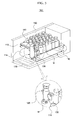
- FIG. 1 is a schematic perspective view of a medicine dispensing device according to an embodiment of the present invention
- FIG. 2 is a view of an internal configuration of a medicine dispensing device according to an embodiment of the present invention.
- a medicine dispensing device 100 may include a medicine mounting portion 110 on which medicines M are mounted and which transports the mounted medicines M, a dispensing portion 120 that pivots between a receiving position at which the medicines M are received and a dispensing position at which the medicines M are dispensed, and a position movement preventing portion 130 that prevents the positions of the medicines M from moving.
- the medicines M may be in vials, as illustrated in FIG. 2 .
- embodiments of the present invention are not limited thereto.
- the medicines M may include medicines having various sizes and shapes, such as ampoules, refined chemicals, powders or pouch type chemicals, or medical instruments such as syringes.
- a plurality of medicine dispensing devices 100 may be mounted on a cartridge. As the cartridge is mounted in layers on which medicine dispensing equipment is mounted, the medicine dispensing device 100 may be mounted in a plurality of layers within the medicine dispensing equipment.
- the medicine dispensing device 100 may store and dispense the medicines M based on a medicine dispensing request, i.e., a prescription for a patient, within the medicine dispensing equipment.
- the operation of keeping and dispensing the medicines M may be implemented by position movement of the medicine mounting portion 110, the dispensing portion 120, and the position movement preventing portion 130.
- the medicine mounting portion 110 may be disposed in a body portion 150.
- the medicines M may be mounted upright on one surface of the medicine mounting portion 110, and when the medicines M are required to be dispensed, the medicine mounting portion 110 may move the medicines M forward through position movement.
- forward may refer to a direction from the medicines M to the dispensing portion 120, and rearward may refer to the opposite direction.
- the medicine mounting portion 110 may include a belt portion 114 on which the medicines M are mounted and transported along an endless belt, and an escape preventing portion 112 that is disposed on the belt portion 114 and prevents the medicines M from escaping from the belt portion 114.
- the escape preventing portion 112 may be fastened to the belt portion 114 and may interlock therewith. However, the escape preventing portion 112 may simply be mounted on one surface of the belt portion 114.
- the escape preventing portion 112 may prevent the medicines M from falling rearward due to inertia when the belt portion 114 moves and stops suddenly. Thus, the medicines M may be aligned to achieve accuracy in sequentially dispensing the medicines M.
- the body portion 150 may include a cover portion 160 for externally exposing the medicine mounting portion 110 so that the medicines M can be replaced.
- the cover portion 160 may be mounted on a top surface of the body portion 150, as illustrated in FIG. 1 .
- cover portion 160 may be mounted at various positions including a side of the body portion 150 according to an intention of one of ordinary skill in the art.
- the dispensing portion 120 may pivot between the receiving position at which the medicines M transported by the medicine mounting portion 110 are received, and the dispensing position at which the received medicines M are dispensed.
- the receiving position may refer to a position before the dispensing portion 120 is pivoted, i.e., a position of a state shown in FIG. 2
- the dispensing position may refer to a position in a state in which pivoting of the dispensing portion 120 is completed, as illustrated in FIG. 5 .
- the dispensing portion 120 receives the medicines M transported by the medicine mounting portion 110 at the receiving position and then is pivoted so that directions in which the medicines M are received and dispensed can be different from each other.
- the direction in which the medicines M are received may refer to a direction in which the medicines M are upright
- the direction in which the medicines M are dispensed may refer to a direction in which the medicines M are laid down.
- the dispensing portion 120 may receive the medicines M mounted on the medicine mounting portion 110 at the receiving position while maintaining the same arrangement state.
- the dispensing portion 120 may include an inner surface that corresponds to at least a part of an outer surface of the medicines M, so as to receive one of the medicines M transported by the medicine mounting portion 110 at the receiving position.
- the dispensing portion 120 may include a surrounding portion 122 that surrounds the part of the outer surface of the medicines M at the receiving position and exposes the other part thereof.
- the received medicines M may be dispensed as a portion exposed by the surrounding portion 122 due to pivoting of the dispensing portion 120.
- the dispensing portion 120 may have a shape in which a part of a side is cut from a hollow cylinder, and the side that remains after being cut may be the surrounding portion 122.
- the dispensing portion 120 may receive the medicines M transported by the medicine mounting portion 110 at the receiving position and then may be pivoted around a portion on which the received medicines M are mounted, so that the received medicines M can be automatically dispensed due to gravity.
- a time at which the medicines M received by the dispensing portion 120 are dispensed may be a time at which the dispensing portion 120 reaches the dispensing position, or before. This may vary according to a contact relationship (frictional coefficient) between the dispensing portion 120 and the medicines M, pivoting speed of the dispensing portion 120 and the size of the surrounding portion 122.
- the position movement preventing portion 130 may prevent position movement of the medicines M to be received later on when the medicines M are received by the dispensing portion 120. Thus, the position movement preventing portion 130 may cause the medicines M to be sequentially mounted on the dispensing portion 120 one at a time.
- the position movement preventing portion 130 may control flow of the medicines M into the dispensing portion 120 according to whether the dispensing portion 120 is pivoted.
- the position movement preventing portion 130 may function as a kind of shutter.
- the position movement preventing portion 130 may control whether the medicines M pass through an outer side of the guide portion 140, which may be implemented according to whether the dispensing portion 120 is pivoted.
- the guide portion 140 is a kind of guide member that may move the medicines M mounted on the medicine mounting portion 110 to a position corresponding to the receiving position.
- the guide portion 140 may include a contact rotation portion 142 that is in contact with the medicines M mounted on the medicine mounting portion 110 and rotates on the endless belt so as to move the contacting medicines M to the outer side of the guide portion 140.
- the contact rotation portion 142 may be a kind of rubber ring having elasticity.
- the medicines M mounted on the medicine mounting portion 110 may pass through the outer side of the guide portion 140 and thus may be received by the dispensing portion 120 placed at the receiving position.
- a space through which only one of the medicines M may pass is formed between one side end of the guide portion 140 and the body portion 150. Opening and closing of the space may be controlled according to whether the position movement preventing portion 130 is pivoted.
- a width that is viewed from an upper side of the guide portion 140 may narrow toward a position corresponding to the receiving position, which may be implemented when one surface on which the contact rotation portion 142 and the medicines M come in contact as a slanted surface.
- a part of the guide portion 140 that formed as a slanted surface is not limited to the one surface on which the contact rotation portion 142 and the medicines M come in contact, but may also be formed on the opposite surface.
- the width of the guide portion 140 in order for the width of the guide portion 140 to narrow toward the position corresponding to the receiving position, it is not necessary for at least surface to be slanted, and the surface may also be formed to be rounded.
- the medicines M that come in contact with the contact rotation portion 142 may be moved forward toward the outer side of the guide portion 140. As a result, positions of the medicines M that come in contact with the contact rotation portion 142 may be different from each other.
- Position movement of the medicine mounting portion 110, the position movement preventing portion 130 and the dispensing portion 120 and rotation of the contact rotation portion 142 may be implemented by a motor that may be disposed in the body portion 150.
- embodiments of the present invention are not limited thereto, and the position movement and the rotation may be implemented by an external force supplied from the outside.
- FIGS. 3 through 5 are views of an internal configuration for explaining an operating principle of a medicine dispensing device according to an embodiment of the present invention.
- the belt portion 114 of the medicine mounting portion 110 is rotated so that the medicines M can be dispensed, and according to rotation of the contact rotation portion 142 of the guide portion 140, the medicines M mounted on the medicine mounting portion 110 flow into the outer side of the guide portion 140.
- the position movement preventing portion 130 may be pivoted and may cause one of the medicines M to pass through the outer side of the guide portion 140.
- the medicine M that passes through the outer side of the guide portion 140 flows into the dispensing portion 120 placed at the receiving position.
- the position movement preventing portion 130 may be returned to its original position and may prevent position movement of the medicines M to be received later on.
- the medicines M can be sequentially dispensed one at a time.
- the dispensing portion 120 that receives the medicines M may be pivoted from the receiving position to the dispensing position. In this procedure, the medicines M may automatically escape from the dispensing portion 120 and may be dispensed outward due to gravity.
- the dispensing portion 120 may be returned to the receiving position and may sequentially dispense the medicines M one at a time according to pivoting of the position movement preventing portion 130 and passing of the medicines M through the outer side of the guide portion 140.
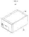
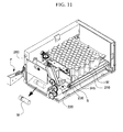
- FIG. 6 is a schematic view of a medicine dispensing device according to another embodiment of the present invention
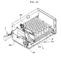
- FIG. 7 is a view of an internal configuration of a medicine dispensing device according to another embodiment of the present invention.
- a medicine dispensing device 200 may include a medicine mounting portion 210 that transports medicines M mounted in an upright state, a dispensing portion 220 that moves between a receiving position at which the medicines M are received and a dispensing position at which the medicines M are dispensed, a position movement preventing portion 230 that prevents position movement of the medicines M, and a guide portion 240 that defines an entrance space S in which the medicines M mounted on the medicine mounting portion 210 enter the dispensing portion 220 at the receiving position.
- the medicines M may be in vials, as illustrated in FIG. 7 .
- embodiments of the present invention are not limited thereto.
- the medicines M may include medicines having various sizes and shapes, such as ampoules, refined chemicals, powders or pouch type chemicals, or medical instruments such as syringes.
- a plurality of medicine dispensing devices 200 may be mounted on a cartridge. As the cartridge is mounted in layers on which medicine dispensing equipment is mounted, the medicine dispensing device 100 may be mounted in a plurality of layers within the medicine dispensing equipment.
- the medicine dispensing device 200 may store and dispense the medicines M based on a medicine dispensing request, i.e., a prescription for a patient, within the medicine dispensing equipment.
- the operation of storing and dispensing the medicines M may be implemented by position movement of the medicine mounting portion 210, the dispensing portion 220, the position movement preventing portion 230, and the guide portion 240.
- the medicine mounting portion 210 may be disposed in a body portion 250.
- the medicines M may be mounted upright on one surface of the medicine mounting portion 210, and when the medicines M are required to be dispensed, the medicine mounting portion 210 may be a kind of conveyor belt that may move the medicines M forward through position movement.
- forward may refer to a direction from the medicines M to the dispensing portion 220, and rearward may refer to the opposite direction.
- the body portion 250 may include a cover portion 260 that externally exposes the medicine mounting portion 210 so that the medicines M can be replaced.
- the cover portion 260 may be mounted on a top surface of the body portion 250, as illustrated in FIG. 6 . However, the cover portion 260 may be mounted at various positions including a side of the body portion 250 according to an intention of one of ordinary skill in the art.
- the receiving position may refer to a position before the dispensing portion 220 is moved, i.e., a position shown in FIG. 7
- the dispensing position may refer to a position at which the medicines M are dispensed by the dispensing portion 220, as illustrated in FIG. 11 .
- the dispensing position may also refer to a position of the medicines M after being dispensed by the dispensing portion 220, undergoing further position movement, and finally completed position movement.
- the dispensing portion 220 receives the medicines M transported by the medicine mounting portion 210 at the receiving position and then is transported, i.e., is rotated at a predetermined angle so that directions in which the medicines M are received and dispensed can be different from each other.
- the dispensing portion 220 may receive the medicines M that enter the entrance space S defined by the guide portion 240 in the upright state at the receiving position and then may dispense the medicines M in a different direction from a direction in which the medicines M are received when the dispensing portion 220 reaches the dispensing position, or before.
- the dispensing portion 220 may receive the medicines M in the upright state and then may be moved to the dispensing position by rotation and may dispense the medicines M in the upright state to be in a laid state.
- the dispensing portion 220 may include a support portion 222 on which the medicines M moved from the medicine mounting portion 210 at the receiving position are mounted while being maintained in the upright state, and a preventing portion 224 that is connected to the support portion 222 so as to prevent escape of the medicines M mounted on the support portion 222.
- the dispensing portion 220 may cause the support portion 222 to be rotated around a rotation shaft 272 using a first driving portion (see 270 of FIGS. 13 through 15 ), and the medicines M mounted on the support portion 222 may be automatically dispensed due to gravity.
- the medicine dispensing device 200 may further include a discharge adjusting portion 280 that adjusts whether the medicines M dispensed by the dispensing portion 220 are discharged to the outside.
- the discharge adjusting portion 280 may be mounted on the body portion 250 so that the discharge adjusting portion 280 can be transported.
- the discharge adjusting portion 280 may be linked to the dispensing portion 220. Thus, when the dispensing portion 220 is moved to the dispensing position, the dispensing portion 220 is moved to be in an open state so that the medicines M can be discharged to the outside.
- the discharge adjusting portion 280 may be an element for preventing position movement of the medicines M to be received later on.
- the medicines M can be sequentially mounted on the dispensing portion 220 one at a time.
- the position movement preventing portion 230 is transported by a driving force of a second driving portion (see 290 of FIGS. 16 and 17 ) so that communication between the entrance space S and the dispensing portion 220 can be prevented.
- a second driving portion see 290 of FIGS. 16 and 17
- the position movement preventing portion 230 may be returned to its original position so that communication between the entrance space S and the dispensing portion 220 can be allowed.
- the medicines M to be dispensed later on can be received by the dispensing portion 220 at the received position.
- the guide portion 240 may be an element that guides the medicines M mounted on the medicine mounting portion 210 toward a position corresponding to the receiving position, defines the entrance space S in which the medicines M enter the dispensing portion 220 at the receiving position, and adjusts the size of the entrance space S based on the sizes of the medicines M.
- the guide portion 240 may adjust the size of the entrance space S in which the medicines M enter the dispensing portion 220, to correspond to the sizes of the medicines M mounted on the medicine mounting portion 210. Thus, even when the sizes of the medicines M are changed, the guide portion 240 may adjust the size of the entrance space S to be suitable for the changed sizes of the medicines M.
- the guide portion 240 may include a reference guide portion 242 that is fixed to a predetermined position of the body portion 250, a varying guide portion 244 mounted on the reference guide portion 242 so as to be transported, and a contact rotation portion 245 that rotates on the endless belt so as to guide the medicines M mounted on the medicine mounting portion 210 to correspond to the receiving position.
- the size of the entrance space S may be changed according to a position at which the varying guide portion 244 is mounted on the reference guide portion 242.
- the reference guide portion 242 and the varying guide portion 244 may include a reference axis X1 and a varying axis X2 for implementing rotation of the contact rotation portion 245.
- a distance between the reference axis X1 and the varying axis X2 is changed by the position at which the varying guide portion 244 is mounted on the reference guide portion 242.
- the distance may be in inverse proportion to the size of the entrance space S.
- FIGS. 20 through 23 A detailed description thereof will be provided with reference to FIGS. 20 through 23 .
- the medicine dispensing device 200 may further include an alignment portion 300 that defines the number of medicines M mounted on the medicine mounting portion 210 and is transported in the same direction in which the medicines M mounted on the medicine mounting portion 210 are transported, so that the medicines M mounted on the medicine mounting portion 210 can be maintained in the upright state when the medicines M mounted on the medicine mounting portion 210 are transported.
- the alignment portion 300 may be moved in a direction opposite to the direction in which the medicines M mounted on the medicine mounting portion 210 are transported only using external force. This will be described with reference to FIGS. 18 and 19 in detail.
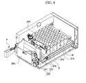
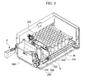
- FIGS. 8 through 11 are views for explaining an operating sequence of a medicine dispensing device according to another embodiment of the present invention.
- the medicines M mounted on the medicine mounting portion 210 pass through the entrance space S provided between one side end of the guide portion 240 and the body portion 250 one at a time due to rotation of the medicine mounting portion 210 and the contact rotation portion 245 of the guide portion 240.
- the position movement preventing portion 230 allows communication between the entrance portion S and the dispensing portion 220.
- the entrance portion S may be provided by the guide portion 240 so as to correspond to the sizes of the medicines M.
- the medicine mounting portion 210 may cause the medicines M that enter the entrance space S to be received by the dispensing portion 220 at the receiving position.
- the medicine M when one medicine M passes through the entrance space S, the medicine M may be received by the dispensing portion 220 placed at the receiving position.
- the position movement preventing portion 230 may be transported so that the medicine M to be dispensed later on cannot pass through the entrance space S, and thus communication between the entrance space S and the dispensing portion 220 is prevented.
- the dispensing portion 220 is moved to the dispensing position by the driving force of the first driving portion 270.
- the discharge adjusting portion 280 is linked to the dispensing portion 220 and is transported together with position movement of the dispensing portion 220.
- the dispensing portion 220 may receive the medicines M in the upright state at the receiving position and then may dispense the medicines M in a different direction from a direction in which the medicines M are received when the dispensing portion 220 reaches the dispensing position, or before.
- the procedure shown in FIGS. 8 through 11 may be repeated so that the medicines M can be sequentially discharged to the outside one at a time.
- FIG. 12 is a view of an operating principle of a medicine mounting portion and a contact rotation portion of a medicine dispensing device according to another embodiment of the present invention.
- the medicine mounting portion 210 and the contact rotation portion 245 of the guide portion 240 may be transported so that the medicines M mounted on the medicine mounting portion 210 can be received by the dispensing portion 220 at the receiving position.
- the driving force for position movement of the medicine mounting portion 210 and the contact rotation portion 245 may be provided by the external force applying portion F.
- the external force applying portion F may include a gear that engages with a first spur gear G1.
- the gear may engage with the first spur gear G1 and then rotate so as to rotate the first spur gear G1.
- a second spur gear G2 When the first spur gear G1 is rotated, as illustrated in FIG. 7 , a second spur gear G2, a third spur gear G3, a fourth spur gear G4, a fifth spur gear G5, a sixth spur gear G6, and a seventh spur gear G7 are rotated, and due to rotation of the fourth spur gear G4, the medicine mounting portion 210 may be rotated on the endless belt.
- the pinion gear P and the ring gear R may be bevel gears, and the contact rotation portion 245 is rotated on the endless belt due to rotation of the ring gear R about the rotation shaft as the reference axis X1 and the varying axis X2.
- position movement of the medicine mounting portion 210 and the contact rotation portion 245 may be implemented by the same driving force provided by the external force applying portion F. Due to the position movement, the medicines M pass through the entrance space S and are received by the dispensing portion 220 at the receiving position.
- the position movement of the medicine mounting portion 210 and the contact rotation portion 245 is not necessarily implemented by the above-mentioned gears but may be implemented by different types of gears or a timing belt.
- FIGS. 13 through 15 are views of an operating principle of a dispensing portion and a discharge adjusting portion of a medicine dispensing device according to another embodiment of the present invention.
- an eighth spur gear G8 is rotated by the driving force provided by the first driving portion 270, and a ninth spur gear G9, a tenth spur gear G10, and an eleventh spur gear G11 are also rotated due to rotation of the eighth spur gear G8.
- a dispensing protrusion P1 mounted on the ninth spur gear G9 is also rotated.
- the dispensing protrusion P1 is in contact with the support portion 222 of the dispensing portion 220 so that the support portion 222 can be rotated about the rotation shaft 272.
- the support portion 222 may include a rounded surface 223 that comes in contact with the dispensing protrusion P1.
- the dispensing protrusion P1 is rotated by rotation of the ninth spur gear G9 and is moved along the rounded surface 223, as illustrated in FIGS. 14 and 15 .
- the dispensing protrusion P1 is moved upward while being rotated.
- the rounded surface 223 is pushed upward so that the support portion 222 can be rotated about the rotation shaft 272.
- the discharge protrusion P2 When the discharge protrusion P2 is rotated, the discharge protrusion P2 is moved along a through hole H1 of a connection portion 282 connected to the discharge adjusting portion 280. Due to the through hole H1 that is formed to be rounded, the connection portion 282 is moved in one direction and rotated.
- the discharge adjusting portion 280 may be moved upward and may cause the medicines M to be discharged to the outside.
- position movement of the dispensing portion 220 and the discharge adjusting portion 280 is not necessarily implemented by the above-described gears but may be implemented by different types of gears or a timing belt.
- FIGS. 16 and 17 are views of an operating principle of a position movement preventing portion of a medicine dispensing device according to another embodiment of the present invention.
- the position movement preventing portion 230 may be transported by a driving force of the second driving portion 290 and may prevent position movement of the medicines M to be received later on.
- a first link portion 232 connected to the second driving portion 290 is rotated by the driving force of the second driving portion 290.
- a second link portion 234 connected to the first link portion 232 is also rotated.
- the position movement preventing portion 230 connected to the second link portion 234 may be moved in a straight direction and may prevent communication between the entrance space S and the dispensing portion 220.
- the position movement preventing portion 230 may be returned to the state shown in FIG. 9 due to rotation of the first link portion 232.
- the position movement preventing portion 230 may allow communication between the entrance space S and the dispensing portion 220 so that the medicines M to be dispensed later on can be dispensed by the dispensing portion 220 at the receiving position.
- FIG. 18 is a view of an alignment portion of a medicine dispensing device according to another embodiment of the present invention
- FIG. 19 is a view for explaining a position movement principle of an alignment portion of a medicine dispensing device according to another embodiment of the present invention.
- an alignment portion 300 that is an element for defining the number of medicines M mounted on the medicine mounting portion 210 may define a space A of the medicine mounting portion 210 in which the medicines M are mounted.
- the alignment portion 300 may include a support portion 310 that supports the medicines M and is in contact with the medicine mounting portion 210 so that the medicines M can be maintained in the upright state without being affected by inertia when the medicines M mounted on the medicine mounting portion 210 are transported, and a hangable portion 320 and a hangable-portion-moving portion 330 that are mounted on the support portion 310 so as to be transported such that the hangable portion 320 and the hangable-portion-moving portion 330 can be in contact with a hanging portion 252 formed on an inner surface of the body portion 250 and can be moved together with the support portion 310.
- the support portion 310 may be transported in the same direction in which the medicines M mounted on the medicine mounting portion 210 are transported due to contact with the medicine mounting portion 210. However, the support portion 310 cannot be moved in a direction opposite to the direction in which the medicines M are transported without an external force.
- the hanging portion 252 may be repeatedly formed as an inclined surface.
- the hangable portion 320 may include an inclined end portion corresponding to the inclined surface.
- the hangable portion 320 may be moved in the same direction in which the medicines M mounted on the medicine mounting portion 210 are transported. However, the hangable portion 320 is hung on a jaw of the hanging portion 252 and cannot be moved in an opposite direction.
- the alignment portion 300 is disposed at a position adjacent to the guide portion 240 and should be moved in the opposite direction for supply of new medicines M.
- both ends of the hangable portion 320 may be rotated so that contact with the hanging portion 252 can be released.
- a space in which new medicines M are to be mounted can be secured again by moving the hangable portion 320 in the opposite direction using the hangable-portion-moving portion 330 in a state in which the hangable portion 320 is spaced apart from the hanging portion 252.
- the hangable portion 320 comes in contact with the hanging portion 252 again due to elasticity.
- FIG. 20 is a schematic perspective view of a guide portion of a medicine dispensing device according to another embodiment of the present invention
- FIG. 21 is a schematic exploded perspective view of a guide portion of a medicine dispensing device according to another embodiment of the present invention
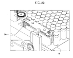
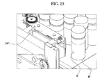
- FIGS. 22 and 23 are views for explaining the size of an entrance space using the guide portion of a medicine dispensing device according to another embodiment of the present invention.
- the guide portion 240 may include a reference guide portion 242 fixed to the body portion 250, a varying guide portion 244 mounted on the reference guide portion 242 so as to be transported, and a contact rotation portion 245 that rotates on the endless belt so as to guide the medicines M mounted on the medicine mounting portion 210 toward a position corresponding to the receiving position.
- the reference guide portion 242 and the varying guide portion 244 may include a reference axis X1 and a varying axis X2 for implementing rotation of the contact rotation portion 245.
- the reference axis X1 and the varying axis X2 may be linked to a reference roller R1 and a varying roller R2 and may be rotated.
- the contact rotation portion 245 may contact the reference roller R1 and the varying roller R2.
- the first reference axis X1 and the reference roller R1 are rotated by rotation of a ring gear R, the first reference axis X1 and the reference roller R1 may be linked to each other and may be moved to the endless belt.
- the contact rotation portion 245 may include a movement portion 246 that is a kind of belt having elasticity and a plurality of pressurization portions 247 that are spaced apart from the movement portion 246 and protrude from the contact rotation portion 245 so as to pressurize the medicines M that come in contact with the movement portion 246 toward the entrance space S.
- One of the reference guide portion 242 and the varying guide portion 244 may include an accommodation portion 248 that is depressed.
- the other may include an insertion portion 249 that is inserted into the accommodation portion 248 and causes a position of the varying guide portion 244 to be fixed to the reference guide portion 242.
- the accommodation portion 248 and the insertion portion 249 may be formed at the reference guide portion 242 and the varying guide portion 244, respectively.
- a plurality of accommodation portions 248 may be spaced apart from each other, and a unit for adjusting the size of the entrance space S may be determined based on a separation distance.
- the guide portion 240 in the state shown in FIG. 23 may be implemented.
- the reference guide portion 242 and the varying guide portion 244 may be fixed to the body portion 250 using a fixing portion 241.
- an entrance space S' may be greater than that of FIG. 22 .
- Medicines M' having relatively larger sizes than those of FIG. 22 may also be dispensed.
- the size of the entrance space S may be determined based on a region in which the reference guide portion 242 and the varying guide portion 244 overlap, and the size of the entrance space S and the region may be in inverse proportion to each other.
Applications Claiming Priority (2)
| Application Number | Priority Date | Filing Date | Title |
|---|---|---|---|
| KR1020130120969A KR102147197B1 (ko) | 2013-10-11 | 2013-10-11 | 의약품 불출 장치 |
| KR1020140126905A KR101652172B1 (ko) | 2014-09-23 | 2014-09-23 | 의약품 불출 장치 |
Publications (1)
| Publication Number | Publication Date |
|---|---|
| EP2860711A1 true EP2860711A1 (de) | 2015-04-15 |
Family
ID=51690855
Family Applications (1)
| Application Number | Title | Priority Date | Filing Date |
|---|---|---|---|
| EP20140187963 Withdrawn EP2860711A1 (de) | 2013-10-11 | 2014-10-07 | Arzneimittelabgabevorrichtung |
Country Status (5)
| Country | Link |
|---|---|
| US (1) | US9598222B2 (de) |
| EP (1) | EP2860711A1 (de) |
| JP (1) | JP2015073908A (de) |
| CN (1) | CN104555209B (de) |
| CA (1) | CA2866906A1 (de) |
Cited By (3)
| Publication number | Priority date | Publication date | Assignee | Title |
|---|---|---|---|---|
| ITUB20153402A1 (it) * | 2015-09-03 | 2017-03-03 | N&W Global Vending S P A | Erogatore di cialde |
| WO2017037675A1 (en) * | 2015-09-02 | 2017-03-09 | N&W Global Vending S.P.A. | Pod dispenser |
| US20180141761A1 (en) * | 2015-06-23 | 2018-05-24 | Nestec S.A. | Capsule dispensing device |
Families Citing this family (13)
| Publication number | Priority date | Publication date | Assignee | Title |
|---|---|---|---|---|
| KR102458354B1 (ko) * | 2015-07-16 | 2022-10-26 | (주)제이브이엠 | 의약품 불출 장치 |
| CN106144378B (zh) * | 2016-06-29 | 2018-09-14 | 苏州信亨自动化科技有限公司 | 瓶装药剂自动发药装置 |
| CN108529021A (zh) * | 2017-12-29 | 2018-09-14 | 天津朗赛生物科技有限公司 | 一种便携式清洁检测试剂盒 |
| CN108685395A (zh) * | 2018-05-18 | 2018-10-23 | 佛山市业鹏机械有限公司 | 一种宠物周边产品展示系统 |
| CN108861288B (zh) * | 2018-06-11 | 2023-12-26 | 苏州宏景松智能科技有限公司 | 一种自动药仓的储发单元仓 |
| US10492625B1 (en) * | 2018-06-15 | 2019-12-03 | ONA Creative, LLC. | Beverage container serving apparatus including movable gate and related methods |
| US20200022507A1 (en) * | 2018-06-15 | 2020-01-23 | ONA Creative, LLC | Beverage container serving apparatus including movable gate and related methods |
| WO2020031499A1 (ja) * | 2018-08-10 | 2020-02-13 | Phcホールディングス株式会社 | 薬品管理システム |
| IT201800009313A1 (it) | 2018-10-10 | 2020-04-10 | Fas Int Spa | Dispositivo per lo stoccaggio e l’erogazione di prodotti. |
| CN111661539A (zh) * | 2020-06-08 | 2020-09-15 | 王韵一 | 一种具有自动存取功能的液氮罐立体存储装置 |
| CN111728428B (zh) * | 2020-07-06 | 2021-08-03 | 河南科技大学第一附属医院 | 一种针剂药贮存装置 |
| CN113566646B (zh) * | 2021-07-23 | 2022-11-15 | 中国人民解放军陆军工程大学 | 一种弹药姿态矫正器 |
| CN114476463A (zh) * | 2022-02-14 | 2022-05-13 | 天心天思(湖州)智能科技有限公司 | 基于转轨堆垛机的自动化模具库 |
Citations (9)
| Publication number | Priority date | Publication date | Assignee | Title |
|---|---|---|---|---|
| EP0414010A1 (de) * | 1989-08-23 | 1991-02-27 | Firma Ulrich Hein | Leitvorrichtung für Flaschen |
| US6202827B1 (en) * | 1997-10-31 | 2001-03-20 | Kalish Canada Inc. | Method and apparatus for feeding containers in serial order on a conveyor belt |
| US20040188455A1 (en) * | 2003-03-28 | 2004-09-30 | Sanden Corporation | Vending machine |
| WO2008043631A1 (en) * | 2006-10-09 | 2008-04-17 | N & W Global Vending S.P.A. | Automatic product vending machine |
| WO2009074851A1 (en) * | 2007-12-11 | 2009-06-18 | N & W Global Vending S.P.A. | Method and device for transferring products in a vending machine |
| WO2009138865A1 (en) * | 2008-05-15 | 2009-11-19 | N&W Global Vending S.P.A | Method of dispensing products off a vending machine tray |
| EP2168556A1 (de) * | 2007-07-02 | 2010-03-31 | Yuyama Mfg. Co., Ltd. | Ampullenbehälter |
| WO2010116245A1 (en) * | 2009-04-09 | 2010-10-14 | N&W Global Vending S.P.A. | Cup dispensing group for a beverage vending machine |
| US20110127288A1 (en) * | 2008-05-14 | 2011-06-02 | Gabriele Valota | Product vending machine |
Family Cites Families (16)
| Publication number | Priority date | Publication date | Assignee | Title |
|---|---|---|---|---|
| US4460106A (en) * | 1981-11-02 | 1984-07-17 | Moulding Jr Thomas S | Pill dispenser |
| ATE196282T1 (de) * | 1993-01-04 | 2000-09-15 | Thomas J Shaw | Automatische pillenabgabevorrichtung |
| US5337919A (en) * | 1993-02-11 | 1994-08-16 | Dispensing Technologies, Inc. | Automatic dispensing system for prescriptions and the like |
| US5405048A (en) * | 1993-06-22 | 1995-04-11 | Kvm Technologies, Inc. | Vacuum operated medicine dispenser |
| US5571258A (en) * | 1995-07-13 | 1996-11-05 | Pearson; Walter G. | Semi-automated medication dispenser |
| US5860563A (en) * | 1997-06-23 | 1999-01-19 | Scriptpro, Llc | Medicine vial dispenser |
| US6427865B1 (en) * | 1998-04-15 | 2002-08-06 | Kenneth Stillwell | Automatic pill dispenser |
| CA2408641C (en) * | 2000-06-05 | 2008-04-15 | Manrex Pty. Ltd. | Medication dispenser |
| US7347341B2 (en) * | 2001-03-09 | 2008-03-25 | Allen Burggraf | Automated medication dispenser |
| US7228198B2 (en) * | 2002-08-09 | 2007-06-05 | Mckesson Automation Systems, Inc. | Prescription filling apparatus implementing a pick and place method |
| US8453874B2 (en) * | 2004-09-02 | 2013-06-04 | Edwin C. Simpson | Pill dispensing apparatus |
| JP4940752B2 (ja) * | 2006-05-11 | 2012-05-30 | 株式会社湯山製作所 | バイアル瓶供給装置 |
| US8251629B2 (en) * | 2007-02-09 | 2012-08-28 | Cerner Innovation, Inc. | Medication dispensing apparatus |
| US20090254214A1 (en) * | 2008-04-03 | 2009-10-08 | Scriptpro Llc | Vial dispensing mechanism |
| CA2638437C (en) * | 2008-07-31 | 2015-08-18 | Leon Saltsov | Medication dispenser |
| CA2802916C (en) * | 2010-07-01 | 2015-11-17 | Pcas Patient Care Automation Services Inc. | Vending machine for storage, labeling and dispensing of a container |
-
2014
- 2014-10-07 EP EP20140187963 patent/EP2860711A1/de not_active Withdrawn
- 2014-10-10 US US14/511,300 patent/US9598222B2/en active Active
- 2014-10-10 CA CA 2866906 patent/CA2866906A1/en not_active Abandoned
- 2014-10-10 CN CN201410533008.4A patent/CN104555209B/zh not_active Expired - Fee Related
- 2014-10-10 JP JP2014209403A patent/JP2015073908A/ja active Pending
Patent Citations (9)
| Publication number | Priority date | Publication date | Assignee | Title |
|---|---|---|---|---|
| EP0414010A1 (de) * | 1989-08-23 | 1991-02-27 | Firma Ulrich Hein | Leitvorrichtung für Flaschen |
| US6202827B1 (en) * | 1997-10-31 | 2001-03-20 | Kalish Canada Inc. | Method and apparatus for feeding containers in serial order on a conveyor belt |
| US20040188455A1 (en) * | 2003-03-28 | 2004-09-30 | Sanden Corporation | Vending machine |
| WO2008043631A1 (en) * | 2006-10-09 | 2008-04-17 | N & W Global Vending S.P.A. | Automatic product vending machine |
| EP2168556A1 (de) * | 2007-07-02 | 2010-03-31 | Yuyama Mfg. Co., Ltd. | Ampullenbehälter |
| WO2009074851A1 (en) * | 2007-12-11 | 2009-06-18 | N & W Global Vending S.P.A. | Method and device for transferring products in a vending machine |
| US20110127288A1 (en) * | 2008-05-14 | 2011-06-02 | Gabriele Valota | Product vending machine |
| WO2009138865A1 (en) * | 2008-05-15 | 2009-11-19 | N&W Global Vending S.P.A | Method of dispensing products off a vending machine tray |
| WO2010116245A1 (en) * | 2009-04-09 | 2010-10-14 | N&W Global Vending S.P.A. | Cup dispensing group for a beverage vending machine |
Cited By (5)
| Publication number | Priority date | Publication date | Assignee | Title |
|---|---|---|---|---|
| US20180141761A1 (en) * | 2015-06-23 | 2018-05-24 | Nestec S.A. | Capsule dispensing device |
| US10793374B2 (en) * | 2015-06-23 | 2020-10-06 | Societe Des Produits Nestle S.A. | Capsule dispensing device |
| WO2017037675A1 (en) * | 2015-09-02 | 2017-03-09 | N&W Global Vending S.P.A. | Pod dispenser |
| US11189124B2 (en) | 2015-09-02 | 2021-11-30 | Evoca S.P.A. | Pod dispenser |
| ITUB20153402A1 (it) * | 2015-09-03 | 2017-03-03 | N&W Global Vending S P A | Erogatore di cialde |
Also Published As
| Publication number | Publication date |
|---|---|
| CN104555209B (zh) | 2019-04-16 |
| CN104555209A (zh) | 2015-04-29 |
| US9598222B2 (en) | 2017-03-21 |
| CA2866906A1 (en) | 2015-04-11 |
| US20150102052A1 (en) | 2015-04-16 |
| JP2015073908A (ja) | 2015-04-20 |
Similar Documents
| Publication | Publication Date | Title |
|---|---|---|
| US9598222B2 (en) | Medicine dispensing device | |
| US11472585B2 (en) | Storage container for automated dispensing of individual medicament portions | |
| EP1852351A1 (de) | Tablettenfüllvorrichtung | |
| US9387153B1 (en) | Metered dispensing system | |
| ES2889625T3 (es) | Recipiente de alimentación de medicamentos para un dispositivo automatizado dispensador de medicamentos | |
| US20160001956A1 (en) | Storage container for automated dispensing of individual medicament portions | |
| KR20140102006A (ko) | 약제 불출 유닛 및 이를 포함하는 약제 불출 장치 | |
| WO2016004530A1 (en) | Mechanism for dispensing pills from an array-type package | |
| JP2019505332A (ja) | カプセルをカットするための携帯装置 | |
| JP6295264B2 (ja) | 薬剤充填装置 | |
| JP6310932B2 (ja) | 薬剤充填装置 | |
| JP6274319B2 (ja) | 薬剤分包装置 | |
| KR20150042398A (ko) | 의약품 불출 장치 | |
| KR102147197B1 (ko) | 의약품 불출 장치 | |
| KR20140055806A (ko) | 파우치형 약제 불출 박스 | |
| KR101652172B1 (ko) | 의약품 불출 장치 | |
| KR102014198B1 (ko) | 약제포장장치 | |
| KR20150145859A (ko) | 약제 불출 장치 | |
| WO2015011764A1 (ja) | 薬剤充填装置 | |
| KR102458354B1 (ko) | 의약품 불출 장치 | |
| KR102286884B1 (ko) | 알약 공급을 위한 공급유도 회전판, 및 이를 포함하는 알약 절단 장치 | |
| KR20140049432A (ko) | 블리스터 포장 약제 불출 박스 | |
| KR20140082252A (ko) | 파우치형 약제 불출 박스 | |
| KR20160074041A (ko) | 의약품 불출 장치 | |
| KR20150030458A (ko) | 의약품 보관 장치 |
Legal Events
| Date | Code | Title | Description |
|---|---|---|---|
| PUAI | Public reference made under article 153(3) epc to a published international application that has entered the european phase |
Free format text: ORIGINAL CODE: 0009012 |
|
| 17P | Request for examination filed |
Effective date: 20141007 |
|
| AK | Designated contracting states |
Kind code of ref document: A1 Designated state(s): AL AT BE BG CH CY CZ DE DK EE ES FI FR GB GR HR HU IE IS IT LI LT LU LV MC MK MT NL NO PL PT RO RS SE SI SK SM TR |
|
| AX | Request for extension of the european patent |
Extension state: BA ME |
|
| R17P | Request for examination filed (corrected) |
Effective date: 20151015 |
|
| RBV | Designated contracting states (corrected) |
Designated state(s): AL AT BE BG CH CY CZ DE DK EE ES FI FR GB GR HR HU IE IS IT LI LT LU LV MC MK MT NL NO PL PT RO RS SE SI SK SM TR |
|
| 17Q | First examination report despatched |
Effective date: 20160122 |
|
| STAA | Information on the status of an ep patent application or granted ep patent |
Free format text: STATUS: THE APPLICATION IS DEEMED TO BE WITHDRAWN |
|
| 18D | Application deemed to be withdrawn |
Effective date: 20170503 |