EP2860318A1 - Gesichertes Verbindungssystem zwischen einem Werkzeug und dem Arm einer Baumaschine - Google Patents
Gesichertes Verbindungssystem zwischen einem Werkzeug und dem Arm einer Baumaschine Download PDFInfo
- Publication number
- EP2860318A1 EP2860318A1 EP20140186501 EP14186501A EP2860318A1 EP 2860318 A1 EP2860318 A1 EP 2860318A1 EP 20140186501 EP20140186501 EP 20140186501 EP 14186501 A EP14186501 A EP 14186501A EP 2860318 A1 EP2860318 A1 EP 2860318A1
- Authority
- EP
- European Patent Office
- Prior art keywords
- locking means
- safety member
- tool
- connection system
- secure connection
- Prior art date
- Legal status (The legal status is an assumption and is not a legal conclusion. Google has not performed a legal analysis and makes no representation as to the accuracy of the status listed.)
- Granted
Links
- 238000001514 detection method Methods 0.000 claims description 56
- 238000006073 displacement reaction Methods 0.000 claims description 28
- 230000009471 action Effects 0.000 claims description 18
- 230000014759 maintenance of location Effects 0.000 claims description 12
- 238000010276 construction Methods 0.000 claims 1
- 238000000034 method Methods 0.000 description 13
- 230000008569 process Effects 0.000 description 13
- 230000000694 effects Effects 0.000 description 8
- 210000000056 organ Anatomy 0.000 description 6
- 230000000717 retained effect Effects 0.000 description 5
- 238000013459 approach Methods 0.000 description 3
- 230000008901 benefit Effects 0.000 description 3
- 230000000295 complement effect Effects 0.000 description 3
- 239000000470 constituent Substances 0.000 description 3
- 230000008878 coupling Effects 0.000 description 3
- 238000010168 coupling process Methods 0.000 description 3
- 238000005859 coupling reaction Methods 0.000 description 3
- 230000006835 compression Effects 0.000 description 2
- 238000007906 compression Methods 0.000 description 2
- 230000009849 deactivation Effects 0.000 description 2
- 238000012423 maintenance Methods 0.000 description 2
- 241000920340 Pion Species 0.000 description 1
- 241001080024 Telles Species 0.000 description 1
- 210000003323 beak Anatomy 0.000 description 1
- 230000000903 blocking effect Effects 0.000 description 1
- 238000011084 recovery Methods 0.000 description 1
- 230000000284 resting effect Effects 0.000 description 1
Images


Classifications
-
- E—FIXED CONSTRUCTIONS
- E02—HYDRAULIC ENGINEERING; FOUNDATIONS; SOIL SHIFTING
- E02F—DREDGING; SOIL-SHIFTING
- E02F3/00—Dredgers; Soil-shifting machines
- E02F3/04—Dredgers; Soil-shifting machines mechanically-driven
- E02F3/28—Dredgers; Soil-shifting machines mechanically-driven with digging tools mounted on a dipper- or bucket-arm, i.e. there is either one arm or a pair of arms, e.g. dippers, buckets
- E02F3/36—Component parts
- E02F3/3604—Devices to connect tools to arms, booms or the like
- E02F3/3609—Devices to connect tools to arms, booms or the like of the quick acting type, e.g. controlled from the operator seat
- E02F3/3622—Devices to connect tools to arms, booms or the like of the quick acting type, e.g. controlled from the operator seat with a hook and a locking element acting on a pin
-
- E—FIXED CONSTRUCTIONS
- E02—HYDRAULIC ENGINEERING; FOUNDATIONS; SOIL SHIFTING
- E02F—DREDGING; SOIL-SHIFTING
- E02F3/00—Dredgers; Soil-shifting machines
- E02F3/04—Dredgers; Soil-shifting machines mechanically-driven
- E02F3/28—Dredgers; Soil-shifting machines mechanically-driven with digging tools mounted on a dipper- or bucket-arm, i.e. there is either one arm or a pair of arms, e.g. dippers, buckets
- E02F3/36—Component parts
- E02F3/3604—Devices to connect tools to arms, booms or the like
- E02F3/3609—Devices to connect tools to arms, booms or the like of the quick acting type, e.g. controlled from the operator seat
- E02F3/3618—Devices to connect tools to arms, booms or the like of the quick acting type, e.g. controlled from the operator seat with two separating hooks
-
- E—FIXED CONSTRUCTIONS
- E02—HYDRAULIC ENGINEERING; FOUNDATIONS; SOIL SHIFTING
- E02F—DREDGING; SOIL-SHIFTING
- E02F3/00—Dredgers; Soil-shifting machines
- E02F3/04—Dredgers; Soil-shifting machines mechanically-driven
- E02F3/28—Dredgers; Soil-shifting machines mechanically-driven with digging tools mounted on a dipper- or bucket-arm, i.e. there is either one arm or a pair of arms, e.g. dippers, buckets
- E02F3/36—Component parts
- E02F3/3604—Devices to connect tools to arms, booms or the like
- E02F3/3609—Devices to connect tools to arms, booms or the like of the quick acting type, e.g. controlled from the operator seat
- E02F3/365—Devices to connect tools to arms, booms or the like of the quick acting type, e.g. controlled from the operator seat with redundant latching means, e.g. for safety purposes
-
- E—FIXED CONSTRUCTIONS
- E02—HYDRAULIC ENGINEERING; FOUNDATIONS; SOIL SHIFTING
- E02F—DREDGING; SOIL-SHIFTING
- E02F3/00—Dredgers; Soil-shifting machines
- E02F3/04—Dredgers; Soil-shifting machines mechanically-driven
- E02F3/28—Dredgers; Soil-shifting machines mechanically-driven with digging tools mounted on a dipper- or bucket-arm, i.e. there is either one arm or a pair of arms, e.g. dippers, buckets
- E02F3/36—Component parts
- E02F3/3604—Devices to connect tools to arms, booms or the like
- E02F3/3609—Devices to connect tools to arms, booms or the like of the quick acting type, e.g. controlled from the operator seat
- E02F3/3663—Devices to connect tools to arms, booms or the like of the quick acting type, e.g. controlled from the operator seat hydraulically-operated
-
- E—FIXED CONSTRUCTIONS
- E02—HYDRAULIC ENGINEERING; FOUNDATIONS; SOIL SHIFTING
- E02F—DREDGING; SOIL-SHIFTING
- E02F3/00—Dredgers; Soil-shifting machines
- E02F3/04—Dredgers; Soil-shifting machines mechanically-driven
- E02F3/28—Dredgers; Soil-shifting machines mechanically-driven with digging tools mounted on a dipper- or bucket-arm, i.e. there is either one arm or a pair of arms, e.g. dippers, buckets
- E02F3/36—Component parts
- E02F3/3604—Devices to connect tools to arms, booms or the like
- E02F3/3609—Devices to connect tools to arms, booms or the like of the quick acting type, e.g. controlled from the operator seat
- E02F3/3672—Devices to connect tools to arms, booms or the like of the quick acting type, e.g. controlled from the operator seat where disengagement is effected by a mechanical lever or handle
Definitions
- the present invention relates to a secure connection system between a tool and an arm of a public works machine.
- the invention also relates to a coupler intended to be mounted at the end of an arm of a public works machine and comprising such a system, and a public works machine equipped with such a coupler.
- the secure connection system according to the invention is intended for a quick coupler assembly.
- the general principle of a quick attachment assembly of a tool on the end of an arm of a public works machine provides the tool with a connection device which usually has male connection means such as pins or pins, and provide the end of the arm of a coupler which has female connection means such as hooks on which engage the male connection means.
- a quick coupler assembly of this type is for example described in the document FR 2 944 534
- This set has a secure connection system comprising a locking means which, in an engaged position, cooperates with the connection device to ensure the retention of the tool.
- a safety member which, in an activated position, prevents inadvertent disengagement of the locking means, which could occur during working operations under certain extreme conditions. Such unwanted disengagement would lead to unwanted release of the tool, which could have damaging consequences for both men and equipment.
- Such a quick coupler assembly makes it possible to connect a tool to an arm of a machine without manual intervention by the driver of the machine and generally satisfies the safety of the connection.
- the present invention aims to overcome the disadvantages mentioned above.
- the invention makes it possible to considerably simplify the process of releasing the the tool.
- the implementation of the secure link system is more convenient and less tedious.
- the invention makes it possible to maintain an automatic connection of the tool, without manual intervention, on the ground, by an operator or the driver of the machine.
- Another advantage of the invention is to further improve the securing of the connection between the coupler - linked to the arm of the machine - and the connection device - linked to the tool - since the safety member is always called upon to its activated position.
- the invention also makes it possible to obtain excellent stability of the system, both in the engaged and disengaged position of the locking means.
- the detection means In the armed position, the detection means is waiting for the tool and ready to be disarmed.
- the return means can urge the locking means from the disengaged position to the position engaged over the entire stroke of the locking means between these two positions.
- Said return means can be fixed on the locking means.
- biasing means biasing the locking means and the biasing means biasing the detection means are distinct, that is to say that the detection means is biased towards a position independently of the means of locking.
- the intermediate position is distinct from the engaged position.
- the secure connection system may further comprise a stop which can occupy a locking position in which it keeps the safety member in the deactivated position, and an unlocking position in which it allows the movement of the safety member towards its position. activated position.
- the stop facilitates the connection of the tool because, when in the locking position, it prevents the operator manually maintain the safety member in the deactivated position, which would be necessary since this safety member is biased to its activated position. By elsewhere, the stop occupies its unlocked position at least when the tool is connected, so as to allow the connection to be secured.
- the abutment may be constituted by one of the constituent elements of the system according to the invention, for example by the locking means or by the detection means.
- the secure connection system can be designed so that, when the detection means is in the armed position, the safety member is kept in its deactivated position.
- This holding can be obtained either directly, the detection means forming the abutment and now itself the safety member, or indirectly, the detecting means holding the locking means which forms the abutment and which holds the safety member .
- the detection means is for example designed to maintain the stop in the locked position when in the armed position.
- connection system can provide that the safety member is kept in the deactivated position at the beginning of the connection process of the tool, then suddenly switches to its activated position. Thus, the security organ can not be activated from the beginning of the connection process.
- the locking means is rotatable between its engaged and disengaged positions.
- the locking means, the safety member and the detecting means are rotatable between their disengaged and engaged, deactivated and activated positions, armed and disarmed, respectively, about substantially parallel axes.
- the release member is rotatable between its first and second positions, about an axis substantially parallel to the axes of rotation of the locking means, of the safety member, and detection means.
- the stop is constituted by a portion of the locking means, the locking means being adapted to, when in the disengaged position, keep the safety member in the deactivated position.
- the locking means may be adapted to maintain the safety member in the deactivated position when the locking means is between its disengaged position and its intermediate position.
- the detection means may be designed to, when in the armed position, keep the locking means in the disengaged position.
- the detection means maintains the locking means, the latter forming the stop which holds the safety member.
- the advantage of keeping the locking means in the disengaged position when the detection means is in the armed position is that the locking means does not occupy the space in which the tool is going to be engaged, and that it is not therefore not necessary, prior to the engagement of the tool, to move the locking means.
- the locking means and the detecting means comprise a pin and the other a recess, the pin being designed to be able to fit in the recess so that the detection means can maintain the means of detection. lock in disengaged position.
- the stop is constituted by a portion of the detection means, the detection means being designed for, when in the armed position, keep the safety member in the off position.
- the detection means forms the stop and maintains itself the safety member.
- the release member is adapted to cause, during its movement from its first position to its second position, simultaneously the movement of the safety member towards its deactivated position and the movement of the locking means towards his position disengaged.
- the relative shapes and arrangements of the safety member and the locking means are designed so that when the locking means reaches its intermediate position, the safety member is no longer in the activated position. The simultaneity of said displacements can take place on the entire movement of the release member from its first position to its second position or only part of this movement.
- the release member is designed to cause, during its movement from its first position to its second position, sequentially the movement of the safety member towards its deactivated position and then, once the safety member is no longer in the activated position, the displacement of the locking means towards its disengaged position.
- the movements of the security organ and locking means are not simultaneous but successive, at least in a first phase of the movement of the release member from its first position to its second position. It should be noted that it is not necessary that the safety member is in the deactivated position so that the locking means can begin to be moved. The important thing is that the safety member is no longer in the activated position when the locking means is in the intermediate position, so as not to prevent further movement.
- the release member is designed, when moving from its first position to its second position, to come into contact on the one hand with the safety member and on the other hand with the means of locking to cause their movements.
- the release member acts directly on the safety member and on the locking means.
- the release member is designed, when moving from its first position to its second position, to come into contact with a movable lever and to cause this lever to move from a waiting position. an actuating position, the lever being designed to, when so moved, come into contact on the one hand with the safety member and on the other hand with the locking means to cause their movements.
- the release member acts indirectly on the safety member and on the locking means via an intermediate lever.
- the release member consists of a removable key adapted to be moved manually by an operator from its first position to its second position.
- the key can be releasably engaged with the locking means and / or the safety member and / or the coupler frame.
- the release action performed by the key on the secure connection system can be obtained directly, or indirectly - that is via an intermediate part.
- the key comprises a contact face formed on a projecting nose and intended to cooperate with a corresponding contact face - generally rounded or oblique - arranged on the safety member, the key and the contact faces being arranged for the rotation of the key from its first position to its second position causes the rotation of the safety member to its deactivated position.
- the key may comprise a means of temporary assembly by means of locking, so that the rotation of the key from its first position to its second position simultaneously causes the rotation of the locking means to its disengaged position and the rotation of the safety member to its deactivated position.
- the release member may comprise a hydraulic actuator permanently mounted on the connection system, or intended to be permanently mounted on the coupler, the actuator being able to be moved from its first position , or retracted position, in its second position, or deployed position, and can be returned to its first position.
- the hydraulic actuator can typically be moved by remote control means, such as a button disposed in the cab of the machine operable by the driver. For the recall of the actuator in its first position, it can be provided that it is biased by biasing means, or that it consists of a double-acting cylinder.
- the secure connection system may further comprise means for indicating the position of the safety member, visible by the driver of the machine, from the cabin.
- These indication means can typically be mechanically linked to the safety member to be simultaneously animated the same movement.
- the visibility of the correct position of the safety device ensures the driver that the connection system has worked properly. In other words, the good position of the indicating means ensures that the locking means are engaged and that the safety member is activated.
- the invention relates to a coupler intended to be mounted at the end of an arm of a public works machine and designed to connect to a connection device attached to a tool, the coupler comprising a system secure link as previously described.
- this coupler may comprise one or two hooks intended to cooperate with one or two journals of the connection device, while the locking means has a convex curved face configured to cooperate by support. with a complementary face provided on the connection device, in operation and when the locking means are in the engaged position.
- this coupler may comprise a hook intended to cooperate with a first axis of the connection device and a notch intended to receive a second axis of the connection device, while the locking means is in the form of a movable hook which, in its engaged position, is adapted to close the notch to trap the second axis of the connection device, in operation.
- the coupler may have one or the other of the aforementioned structures.
- a secure connection system 10 is mounted on the coupler 5 and is intended to cooperate with the connection device 4, in the connected position of the tool 1.
- the coupler 5 generally comprises two flanges 6 substantially parallel and spaced apart from each other in a transverse direction Y.
- longitudinal direction X is defined as the substantially horizontal direction and parallel to the mean plane of the flanges 6.
- front and rear will be used with reference to the direction X and a movement of the machine forward.
- the vertical direction Z is also defined, with respect to which the terms “upper”, “lower” and the like will be used.
- Figures 2 to 22 illustrate a secure connection system 10 and a coupler 5 according to a first embodiment of the invention.
- the coupler 5 comprises a hook 7 formed on each of its flanges 6, at a first longitudinal end portion of the coupler 5.
- the secure connection system 10 is mounted between the two flanges 6, at the second longitudinal end portion of the coupler 5.
- the connecting device 4 fixed on the tool 1 it comprises firstly two substantially transverse and coaxial pins 8 intended to cooperate each with a hook 7, and on the other hand an interface 9 intended to cooperate with the secure connection system 10.
- the secure link system 10 is described with reference to Figures 3 to 8 .
- the secure connection system 10 comprises a substantially cylindrical rod 11, of axis 12, arranged transversely and fixed to the flanges 6, to the second longitudinal end portion of the coupler 5.
- each of the transverse ends of the bar 11 can be mounted in an orifice formed in the flange 6 corresponding.
- a locking means 13 shown more specifically on the figure 7 .
- the locking means 13 comprises a substantially annular base 14, engaged on the bar 11, from which projects, towards the rear, a substantially planar plate 15 parallel to a plane (X, Z).
- the core 15 has at its front portion an orifice 16.
- the locking means 13 further comprises a curved wall 17 located at the end of the core 15 opposite the base 14.
- the wall 17 has a convex functional face 18 .
- the wall 17 comprises a front face 23.
- the locking means 13 and the bar 11 are the main elements of the secure connection system 10 intended to cooperate with the interface 9 of the connection device 4 fixed to the tool 1.
- the figures 2 , 9 and 10 show more precisely the quick coupler assembly 3, the tool 1 being being connected to the arm 2.
- the hooks 7 are located at the rear of the coupler 5 and are open to the opposite of the machine; they are caught on the pins 8 of the connection device 4.
- the interface 9 of the connection device 4 is located in front of the pins 8 and comprises a functional face 20, directed forwardly.
- the face 20 may be substantially planar.
- the face 20 of the interface 9 is functionally complementary to the face 18 of the locking means 13.
- the interface 9 may further comprise notches 21 intended to receive the bar 11 in support.
- locking means 13 is biased towards its engaged position by return means, here comprising two torsion springs 22.
- the secure connection system 10 further comprises a safety member 25, more particularly illustrated on the figure 6 .
- the safety member 25 comprises, at its front portion, a through hole 26 in which is fixedly engaged a rod 27 of substantially transverse axis 28.
- the rod 27 is rotatably mounted in bearings 29 of the coupler 5 (see FIG. figure 3 and 4 ), and comprises two flats 30.
- Each of the bearings 29 comprises a housing in which is engaged a compression spring 32 whose upper end bears on one of the flats 30.
- the safety member 25 is biased from its deactivated position to its position activated by the springs 32, through the flats 30 and the rod 27.
- the safety member 25 has a substantially flat bottom face 33 and a stop face 34 which is substantially transverse and perpendicular to the lower face 33 and which faces towards the rear. Above the stop face 34, the safety member 25 has a rear part raised in the shape of a beak 35. The safety member 25 is further delimited by two lateral faces 36 substantially perpendicular to the Y axis. In the junction area between the lower face 33 and the stop face 34, the safety member 25 has a contact face 37. In the embodiment shown, the contact face 37 forms a chamfer. Alternatively, the contact face 37 could be rounded or have a cam-like profile, and / or not extend over the entire transverse dimension of the security member 25.
- the detection means 40 is rotatably mounted on a shaft 41 of substantially transverse axis 42 fixed to the flanges 6.
- the detection means 40 is disposed at the rear of the locking means 13 and the safety member 25. It is biased by return means 43 to its armed position, and can be moved, under the action of the connecting device 4 during connection and against said biasing means 43, to its disarmed position.
- the detection means 40 may for example be in the form of a finger.
- the secure connection system 10 comprises a release member designed to release the connection device 4 from the coupler 5.
- the release member is in the form of a key 45 illustrated on the figure 8 .
- the key 45 comprises a handle 46 on which the operator will be able to press to rotate the key 45 from a first position - high - to a second position - low, about a substantially transverse axis.
- the upper face of the nose 49 forms a convex contact face 50.
- the contact face 50 of the key is intended to cooperate with the contact face 37 of the safety member 25, for the release of the tool 1.
- the coupler 5 is tilted relative to the tool 1, so that the bar 11 approaches the interface 9 ( figure 9 then figure 10 ).
- the quick coupler assembly 3 is in the position shown in FIG. figure 11 .
- the detecting means 40 is in its armed position, and its front end forms a lug which is engaged and retained in the recess 19 of the locking means 13. As a result, the detecting means 40 holds the locking means 13 in position. its disengaged position, against the springs 22 which urge the locking means 13 to its engaged position. Consequently, there exists under the coupler 5 a free space in which the interface 9 of the connection device 4 can be introduced.
- the functional face 18 is held substantially oriented towards the safety member 25. Under the action of the springs 32 urging the safety member 25 towards its activated position, the lower face 33 of the safety member 25 is held in position. pressing against the functional face 18 of the locking means 13, and the locking means 13 thus keeps the safety member 25 in its deactivated position. The functional face 18 thus forms a stop in the locked position, which keeps the safety member 25 in the deactivated position.
- connection device 4 comes into contact with the connection system 10. More precisely, as illustrated in FIG. figure 12 a part of the interface 9 - here a protuberance 56 formed above the functional face 20 - comes into contact with the detection means 40, on the lower face thereof, and tends to raise it against return means 43, to move it to its disarmed position. Prior to this step, the protrusion 56 may have caused a slight displacement of the locking means 13 to its disengaged position.
- the locking means 13 continues to keep the safety member 25 in the deactivated position, the safety member 25 being in abutment on the functional face 18. Then, as shown in FIG. figure 13 , the locking means 13 has reached a position where the lower face 33 of the safety member 25 is no longer abutted on the functional face 18: the safety member, which is no longer maintained, then switches to its activated position under the effect of the springs 32. The stop formed by the functional face 18 is thus in the unlocking position, allowing the movement of the safety member towards its activated position.
- the locking means 13 continues its movement until it reaches its engaged position, the safety member 25 reaching its activated position. In this position, illustrated on the figure 14 , the quick coupler assembly 3 and the secure connection system 10 are in the normal position of use.
- the functional faces 18 and 20 are in contact and ensure the retention of the tool 1 connected to the arm 2.
- the secure connection system 10 would prevent a total disengagement of the locking means 13.
- the stop face 34 of the safety member 25 cooperating with the front face 23 of the locking means 13 is able to hinder the movement of the locking means 13 to its disengaged position.
- This safety position where the faces 34, 23 are in contact, is illustrated on the figure 15 and corresponds to an intermediate position of the locking means 13.
- the clearance j is determined so that the overlap d between the functional faces 18 and 20 is sufficient to ensure the retention of the tool 1 safely.
- the intermediate position of the locking means 13 is the limit position beyond which the locking means 13 can not hold the tool 1.
- the quick coupler assembly 3 being in its normal position of use (illustrated in FIG. figure 14 ), the key 45 is inserted between the locking means 13 and the safety member 25, as shown in FIG. figure 16 .
- the pin 47 is engaged in the hole 16 of the locking means 13, then the operator presses the handle 46 to pivot the key 45 from its first position, or up position ( figure 16 ) at its second position, or down position ( figure 20 ).
- the rotation of the key 45 from its first position to its second position simultaneously causes the rotation of the locking means 13 towards its disengaged position and the rotation of the safety member 25 towards its deactivated position.
- the figure 17 illustrates a first phase of this double displacement.
- the various constituent elements of the secure connection system 10 - in particular the locking means 13, the safety member 25 and the key 45 - are designed and arranged so that, when the locking means 13 reaches its intermediate position, the safety member 25 is no longer in the activated position, which would cause a blockage of the system and prevent further movement of the key to result in the release of the tool 1.
- the safety member 25 Since the stop face 34 of the safety member 25 is no longer opposite the front face 23 of the locking means 13, the safety member 25 no longer impedes the further movement of the locking means 13 until 'to its disengaged position.
- the nose 49 is no longer in contact with the safety member 25.
- the safety member 25 is now retained in its deactivated position by the abutment contact of the lower faces 33 and functional 18.
- the means of detection 40 is in the armed position.
- the locking means 13 tends to be moved to its engaged position by the springs 22. This movement is prevented because the detection means 40 which is in the armed position and which is housed in the recess 19, as illustrated more precisely on the figure 21 . This ensures the maintenance of the locking means 13 in the disengaged position and, consequently, the holding of the safety member 25 in the deactivated position.
- the secure connection system 10 is then again in the position of the figure 11 , ready for connecting another tool 1.
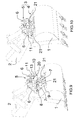
- the figure 22 illustrates more precisely a possible embodiment of the indication means 38 of the position of the safety member 25.
- the indicating means 38 not only have an orientation corresponding to that of the safety member 25, but in addition can be placed in alignment with a mark 57 formed on the coupler 5 when the safety member 25 is in the activated position - or in the deactivated position.
- the indicating means 38 consist of a shoulder forming a line, while the mark 57 consists of the edge of a relief formed on a flange 6, this is not limiting.
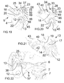
- FIG. 23 illustrate a secure connection system 110 and a coupler 105 according to a second embodiment of the invention.
- An element of the secure connection system 110 or the coupler 105 which is identical or corresponding, in structure or function, respectively to an element of the secure connection system 10 or the coupler 5, has the same numerical reference increased by 100.
- the coupler 105 comprises two flanges 106, a single flange being represented on the figure 32 to facilitate understanding.
- the coupler 105 On each of its flanges 106, the coupler 105 comprises, at a first longitudinal end portion, a hook 107, here open towards the machine and, at a second longitudinal end portion, a notch 131, open downwards.
- the secure connection system 110 is mounted between the two flanges 106, in the vicinity of the notches 131.
- connection device 104 fixed on the tool 1 comprises a first axis 108 and a second axis 109 - which belongs to the interface - substantially transverse and parallel, intended to cooperate one with the hook 107, the other with the notch 131 of the coupler 105.
- the secure connection system 110 comprises a substantially cylindrical bar 111 of axis 112, arranged transversely and fixed to the flanges 106, at the second longitudinal end portion of the coupler 5.
- the locking means 113 On the bar 111 is mounted a locking means 113, which may be in the form of a part having side faces 160 substantially parallel to the flanges 106.
- the locking means 113 comprises a base 114 provided with an orifice 161 substantially transversely in which is engaged the bar 111.
- the base 114 is here located at a first end portion of the locking means 113 which, when the tool 1 is connected to the arm 2, is located substantially towards the front and towards the top of the coupler 105.
- the locking means 113 further includes a hook-shaped portion 163, generally at the second end portion of the locking means 113, opposite the base 114.
- a pin 164 extending substantially transversely from a side face 160 towards the flange 106 adjacent.
- the locking means 113 comprises, on its rear face - opposite to the opening of the hook 163 - on the one hand an oblique face 165 and on the other hand a notch extending the oblique face 165 in the direction of the base 114 and having a bottom face 166 and a locking face 167 substantially perpendicular to each other.
- the locking means 113 is biased towards its engaged position by return means, here comprising a spring 122.
- the secure connection system 110 further comprises a safety member 125.
- the safety member 125 comprises an annular base 170 integral with a rod 127 of substantially transverse axis 128.
- the rod 127 is rotatably mounted in bearings made in the flanges 106.
- the safety member 125 further comprises a substantially radial finger 171 having a stop face 134 and a locking face 172.
- these indicating means 138 are attached to one end of the rod 127, outside a flange 106. Being connected in rotation to the rod 127, itself rotatably connected to the safety member 125 these indicating means 138 may reflect the position of the security member 125 between its deactivated and activated positions.
- the safety member 125 is biased from its deactivated position to its activated position by a torsion spring 132.
- the detection means 140 is rotatably mounted about a substantially transverse axis 142 attached to the flanges 106, and disposed in front of the locking means 113. It has a recess 173 (see in particular the figure 24 ) open towards the rear, and intended to cooperate with the pin 164 as will be described later. It also comprises a lower face 182 intended to cooperate with the axis 109 of the connection device 104.
- the detection means 140 is biased by return means 143 towards its armed position, and can be moved, under the action of the connecting device 104 during connection and against said return means 143, to its position. disarmed.
- the secure connection system 110 comprises a lever 175 movable in rotation with respect to one of the components of the connection system 110 or with respect to the flanges 106, for example on the side of the locking means 113 opposite by means of 140.
- the lever 175 comprises, at the front, a flange having a front face 176 adapted to cooperate with the release means and a rear face 179 adapted to cooperate with the locking means 113.
- the lever further comprises a rear portion 177 adapted to cooperate with the security organ 125.
- the secure link system 110 also includes a release member configured to release the connection device 104 from the linkage system 110.
- this release member may be in the form of a hydraulic actuator 180 mounted on the secure connection system 110 or on the coupler 105 and can be moved from a retracted position ( figure 23 in particular) to a deployed position ( figure 28 especially).
- the hydraulic actuator 180 can be returned to its retracted position, for example by a return spring 181, as shown in FIG. figure 31 .
- the quick coupler assembly 103 is in the position shown in FIG. figure 23 .
- the detection means 140 is in its armed position, its lower face 182 being located at the right of the notch 131, that is to say lower than the bottom 183 of the notch 131.
- the recess 173 provided to the rear end of the detection means 140 cooperates with the pin 164 formed on the locking means 113. Accordingly, and because of the bias exerted by the spring 143, the detection means 140 maintains the locking means 113 in its position disengaged, against the spring 122 which urges the locking means 113 to its engaged position. There is thus under the coupler 105 a free space in which the axis 109 of the connection device 104 can be introduced.
- lever 175 is arranged so that its rear portion 177 is located - transversely - in correspondence with the notch of the locking means 113, and the rear face 179 of the flange is against the locking means 113.
- the coupler 105 is tilted with respect to the tool 1, so that the axis 109 enters the notch 131.
- the recess 173 no longer cooperates with the pin 164. It follows that the locking means 113, which is no longer held by the detection means 140, is moved, under the action of the spring 122, to its engaged position.
- the finger 171 of the safety member 125 moves, due to the spring 132, forwardly and along the oblique face 165 of the locking means 113, until reaching the notch. Once reached the notch, the safety member 125, which is no longer maintained, then switches to its activated position under the effect of the spring 132, the finger 171 being housed in the notch. The stop formed by the oblique face 165 is thus in the unlocking position, allowing the movement of the safety member towards its activated position.
- the figure 25 shows the quick coupler assembly 103 and the secure link system 110 in the normal position of use.
- the locking means 113 is in its engaged position, the axis 109 being held in the notch 131 by the hook 163, ensuring the retention of the tool 1 connected to the arm 2.
- the safety member 125 is in its position activated, housed in the notch of the locking means 113, the locking face 172 of the finger 171 being in contact with the locking face 167 of the notch of the locking means 113.
- the lever 175 since the lever 175 has been pushed by the finger 171 it is now placed so that its rear portion 177 is substantially in contact with the locking face 172 of the safety member.
- the secure connection system 110 would prevent a total disengagement of the means of disengagement. 113.
- the stop face 134 of the safety member 125 cooperating with the bottom face 166 of the notch of the locking means 113 is able to hinder the movement of the locking means 113 to its disengaged position.
- This safety position where the faces 134, 166 are in contact, is illustrated on the figure 26 , and corresponds to an intermediate position of the locking means 113.
- the game j is determined so that the recovery of figure 26 ) between the hook 163 and the axis 109 is sufficient to ensure the retention of the tool 1 safely.
- the hydraulic actuator 180 is moved to its deployed position, which leads to the movement of the lever 175 to an actuated position.
- the detection means under the action of the spring 143, returns to its armed position and maintains the locking means 113 in its disengaged position, via the pin 164 housed in the recess 173.
- the hydraulic actuator 180 can thus be returned to its retracted position ( figure 30 ), without this causing the locking means 113 to move towards its engaged position.
- the release member is therefore designed to cause, during its movement from its first position to its second position, sequentially the displacement of the safety member 125 towards its deactivated position and, once the safety member 125 is no longer in the activated position, the displacement of the locking means 113 towards its disengaged position.
- the key 145 is inserted in front of the locking means 113, as shown in FIG. figure 32 , so that the pin 116 of the locking means 113 is housed in the recess 178 and the nose 149 comes to bear with the front face 176 of the rim of the lever 175. Then the operator presses the handle 146 to rotate the key 145 from his first position to his second position.
- the key can be removably engaged with the safety member 125 and / or the frame of the coupler 105.
- an advantage of this second embodiment is that the release of the tool 1 can be obtained in two different ways, via a manual action on a key, or remotely via an action on a hydraulic actuator.
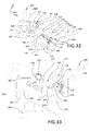
- Figures 34 to 46 illustrate a secure link system 210 and a coupler 205 according to a third embodiment of the invention.
- the secure link system 210 is described with reference to Figures 34 and 35 .
- the secure connection system 210 comprises a substantially cylindrical bar 211, of axis 212, arranged transversely and fixed to the flanges 206, to the second longitudinal end portion of the coupler 205.
- each of the transverse ends of the bar 211 can be mounted in an orifice formed in the corresponding flange 206.
- the locking means 213 comprises a substantially annular base 214, engaged on the bar 211, from which projects, towards the rear, a core 215 substantially flat and parallel to a plane (X, Z).
- the core 215 has at its front a hole 216.
- the locking means 213 further comprises a curved wall 217 located at the end of the core 215 opposite the base 214.
- the wall 217 has a convex functional face 218 .
- the wall 217 comprises a front face 223.
- the locking means 213 and the bar 211 are the main elements of the secure connection system 210 intended to cooperate with the interface 209 of the connection device 4 fixed to the tool 1.
- the figure 36 shows more precisely the quick coupling assembly 203, the tool 1 being being connected to the arm 2.
- the hooks 207 are located at the rear of the coupler 205 and are open to the opposite of the machine; they come to be caught on the pins 208 of the connection device 204.
- the interface 209 of the device of connection 204 is located at the front of the journals 208 and comprises a functional face 220, directed towards the front.
- the face 220 may be substantially flat.
- the face 220 of the interface 209 is functionally complementary to the face 218 of the locking means 213.
- the interface 209 may further comprise notches 221 intended to receive the bar 211 in support.
- the locking means 213 is biased towards its engaged position by return means, here comprising two torsion springs 222.
- the secure connection system 210 further comprises a security member 225.
- the safety member 225 comprises, at its front portion, a through hole 226 in which is fixedly engaged a rod 227 of axis 228 substantially transverse.
- the rod 227 is rotatably mounted in bearings 229 of the coupler 205 (see FIG. figures 34 and 36 ), and comprises two flats 230.
- Each of the bearings 229 comprises a housing in which is engaged a compression spring 232 whose upper end bears on one of the flats 230.
- the safety member 225 is biased from its deactivated position to its position activated by the springs 232, through the flats 230 and the rod 227.
- the safety member 225 has a substantially flat bottom face 233 and a stop face 234 which is substantially transverse and perpendicular to the bottom face 233 and which faces rearwards. Above the stop face 234, the safety member 225 has a rear part raised in the form of spout 235. The safety member 225 is further delimited by two lateral faces 236 substantially perpendicular to the Y axis. In the junction area between the lower face 233 and the stop face 234, the safety member 225 has a contact face 237. In the embodiment shown, the contact face 237 forms a chamfer. As a variant, the contact face 237 could be rounded or have a cam-type profile, and / or not extend over the entire transverse dimension of the safety member 225.
- the safety member 225 further includes a pin 251 located under the spout 235 and which projects laterally beyond a side face 236.
- these indication means 238 are attached to one end of the rod 227, outside a flange 206. Being connected in rotation to the rod 227, itself linked in rotation to the safety member 225, these indication means 238 may reflect the position of the security member 225 between its deactivated and activated positions.
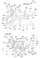
- the detection means 240 is rotatably mounted on a rod 241 of substantially transverse axis 242 fixed to the flanges 206.
- the detection means 240 is disposed laterally by means 213 and the safety member 225, so as to cooperate with the pin 251 of the safety member 225, as shown in the figure 34 and 35 .
- the detection means 240 is biased by return means 243 towards its armed position, and can be moved, under the action of the connecting device 204 during connection and against said return means 243, to its position. disarmed.
- the detection means 240 may be in the form of a part having lateral faces 285 substantially parallel to the lateral faces 236 of the safety member 225. From the axis 242, the detection means 240 comprises a tail 286 directed rearward and an appendix 287 extending towards the safety member 225. The appendix 287 is provided with a notch 288 having a bottom face 289 and a locking face 290 substantially perpendicular to each other. The notch 288 is connected to the shank 286 by an oblique face 291.
- the return means 243 can be connected to the detection means 240 in an area opposite the shank 286 with respect to the axis 242.
- the secure connection system 210 comprises a release member designed to release the connection device 204 from the coupler 205.
- the release member is in the form of a key 245 illustrated on FIG. the figure 35 .
- the upper face of the nose 249 forms a convex contact face 250.
- the contact face 250 of the key is intended to cooperate with the contact face 237 of the safety member 225, for the release of the tool 1.
- the coupler 205 is tilted with respect to the tool 1, so that the bar 211 approaches the interface 209.
- the quick coupler 203 is in the position shown in FIG. figure 36 .
- the detection means 240 is in its armed position. In this position, the pin 251 of the security member 225 is housed in the notch 288 of the detection means 240, and more precisely rests on the bottom face 289. As a result, the detection means 240 maintains the safety member 225 in its deactivated position, against the springs 232 which urge the safety member 225 to its activated position. The bottom face 289 of the detection means 240 thus forms a stop in the locked position, which keeps the safety member 225 in the deactivated position.
- the locking means 213 is in its engaged position, due to the action exerted by the springs 222.
- connection device 204 comes into contact with the connection system 210. More precisely, as illustrated in FIG. figure 36 , a part of the interface 209 - here a protuberance 256 formed above the functional face 220 - comes into contact with the locking means 213, on the lower face of the wall 217, and tends to lift against return means 222, to move it to its disengaged position, as can be seen by comparing the Figures 36 and 37 .
- connection device 204 brings into contact a portion of the interface 209 - here a protuberance 256 'formed above the functional face 220 - with the detection means 240 ( figure 38 ).
- the detection means 240 is thus displaced, against the force exerted by the spring 243, towards its disarmed position.
- the bottom face 289 of the notch 288 moves under the pin 251 of the safety member 225.
- the pin 251 escapes the notch 288.
- the stop formed by the bottom face 289 occupies an unlocking position, and allows the movement of the safety member 225 to its activated position, under the effect of the springs 232.
- the lower face 233 of the safety member 225 abuts against the operative face 218 of the locking means 213, the safety member 225reste maintained in its disabled position ( figure 40 ).
- the figure 40 illustrates the end of the phase of the connection process of the tool 1 where the protuberance 256 is in contact with the locking means 213.
- the locking means 213 When the connection process of the tool 1 continues, the locking means 213 is no longer supported on the protrusion 256. Because of the springs 222, the locking means 213 switches to its engaged position, the functional faces 218 and 220 cooperating to ensure the retention of the tool 1 on the arm 2.
- the locking means 213 has reached a position where the lower face 233 of the safety member 225 no longer abuts on the functional face 218: the safety member, which is no longer maintained, then switches to its position activated by the effect of the springs 232.
- the stop formed by the functional face 218 is thus in the unlocking position, allowing the movement of the safety member towards its activated position.
- the detection means 240 remains in its disarmed position, resting on the protuberance 256 '.
- the quick coupling assembly 203 and the secure connection system 210 are then in the position illustrated on the figure 41 , which corresponds to the normal position of use.
- the functional faces 218, 220 are in contact and ensure the retention of the tool 1 connected to the arm 2.
- the secure connection system 210 would prevent a total disengagement of the locking means 213.
- the stop face 234 of the safety member 225 cooperating with the front face 223 of the locking means 213 is able to hinder the movement of the locking means 213 to its disengaged position.
- This safety position where the faces 234, 223 are in contact, is illustrated on the figure 42 , and corresponds to an intermediate position of the locking means 213.
- the clearance j is determined so that overlap d between the functional faces 218 and 220 is sufficient to ensure the retention of the tool 1 safely.
- the intermediate position of the locking means 213 is the limit position beyond which the locking means 213 can not hold the tool 1.
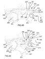
- the quick coupler 203 being in its normal position of use (illustrated in FIG. figure 41 key 245 is inserted between the locking means 213 and the safety member 225, as shown in FIG. figure 43 .
- the stud 247 is engaged in the hole 216 of the locking means 213, then the operator presses the handle 246 to pivot the key 245 from its first position, or up position ( figure 43 ) at its second position, or down position ( figure 45 ).
- the movement of the key 245 towards its second position causes the locking means 213 to move towards its disengaged position.
- the contact face 250 of the nose 249 of the key 245 comes into contact with the contact face 237 of the safety member 225 and lifts it to its deactivated position.
- the rotation of the key 245 from its first position to its second position simultaneously causes the locking means 213 to rotate to its disengaged position and the rotation of the safety member 225 to its deactivated position.
- the figure 43 illustrates a first phase of this double displacement.
- the various constituent elements of the secure connection system 210 - in particular the locking means 213, the safety member 225 and the key 245 - are designed and arranged so that, when the means the locking member 213 reaches its intermediate position, the safety member 225 is no longer in the activated position, which would cause a blockage of the system and prevent further movement of the key to result in the release of the tool 1.
- the specific shape of the protruding nose 249, the contact faces 237, 250 and the lower face 233 leads to a displacement of the safety member 225 to its deactivated position before the locking means 213, pulled towards its position disengaged by the pivoting of the key 245, does not reach its intermediate position.
- the stop face 234 of the safety member 225 is no longer opposite the front face 223 of the wall 217 of the locking means 213, the safety member 225 no longer hinders the further movement of the means. locking 213 to its disengaged position.
- the locking means 213 returns to its engaged position, under the effect of the springs 222 accompanied by the operator by means of the key 245.
- the invention is not limited to the presence of a single locking means and a single safety member.
Landscapes
- Engineering & Computer Science (AREA)
- Mechanical Engineering (AREA)
- Mining & Mineral Resources (AREA)
- Civil Engineering (AREA)
- General Engineering & Computer Science (AREA)
- Structural Engineering (AREA)
- Quick-Acting Or Multi-Walled Pipe Joints (AREA)
- Portable Nailing Machines And Staplers (AREA)
- Auxiliary Devices For Machine Tools (AREA)
Applications Claiming Priority (1)
| Application Number | Priority Date | Filing Date | Title |
|---|---|---|---|
| FR1359969A FR3011859B1 (fr) | 2013-10-14 | 2013-10-14 | Systeme de liaison securisee entre un outil et un bras d’un engin de travaux publics |
Publications (2)
| Publication Number | Publication Date |
|---|---|
| EP2860318A1 true EP2860318A1 (de) | 2015-04-15 |
| EP2860318B1 EP2860318B1 (de) | 2016-07-20 |
Family
ID=49876858
Family Applications (1)
| Application Number | Title | Priority Date | Filing Date |
|---|---|---|---|
| EP14186501.4A Active EP2860318B1 (de) | 2013-10-14 | 2014-09-26 | Gesichertes Verbindungssystem zwischen einem Werkzeug und dem Arm einer Baumaschine |
Country Status (3)
| Country | Link |
|---|---|
| EP (1) | EP2860318B1 (de) |
| ES (1) | ES2596414T3 (de) |
| FR (1) | FR3011859B1 (de) |
Citations (4)
| Publication number | Priority date | Publication date | Assignee | Title |
|---|---|---|---|---|
| US4958848A (en) * | 1989-05-01 | 1990-09-25 | Nash Boyd B | Pintle type trailer coupling |
| US20070166143A1 (en) * | 2006-01-13 | 2007-07-19 | Hart Michael D | Quick coupler lock system |
| WO2008031590A2 (en) * | 2006-09-13 | 2008-03-20 | Ian Hill | Coupler for excavators |
| FR2944534A1 (fr) | 2009-04-20 | 2010-10-22 | Morin | Module de blocage pour un ensemble d'attache rapide d'un outil sur un engin de travaux publics. |
Family Cites Families (1)
| Publication number | Priority date | Publication date | Assignee | Title |
|---|---|---|---|---|
| FR2993584B1 (fr) * | 2012-07-17 | 2014-07-25 | Thiere Ets | Dispositif de montage rapide a securite renforcee, d'un outil pivotant sur le bras d'une machine |
-
2013
- 2013-10-14 FR FR1359969A patent/FR3011859B1/fr not_active Expired - Fee Related
-
2014
- 2014-09-26 EP EP14186501.4A patent/EP2860318B1/de active Active
- 2014-09-26 ES ES14186501.4T patent/ES2596414T3/es active Active
Patent Citations (5)
| Publication number | Priority date | Publication date | Assignee | Title |
|---|---|---|---|---|
| US4958848A (en) * | 1989-05-01 | 1990-09-25 | Nash Boyd B | Pintle type trailer coupling |
| US20070166143A1 (en) * | 2006-01-13 | 2007-07-19 | Hart Michael D | Quick coupler lock system |
| WO2008031590A2 (en) * | 2006-09-13 | 2008-03-20 | Ian Hill | Coupler for excavators |
| FR2944534A1 (fr) | 2009-04-20 | 2010-10-22 | Morin | Module de blocage pour un ensemble d'attache rapide d'un outil sur un engin de travaux publics. |
| EP2243883A2 (de) * | 2009-04-20 | 2010-10-27 | Morin | Verriegelungsmodul für Schnellkuppler an einer Arbeitsmaschine |
Also Published As
| Publication number | Publication date |
|---|---|
| FR3011859A1 (fr) | 2015-04-17 |
| FR3011859B1 (fr) | 2017-06-16 |
| EP2860318B1 (de) | 2016-07-20 |
| ES2596414T3 (es) | 2017-01-09 |
Similar Documents
| Publication | Publication Date | Title |
|---|---|---|
| EP1774106B1 (de) | Vorrichtung zur kopplung eines laders an einen traktor | |
| EP1644604B1 (de) | Zunge zum verbinden zweier verkleidungen einer flugzeugstruktur | |
| FR2875767A1 (fr) | Dispositif de verrouillage d'une batterie de chariot elevateur | |
| EP1586708A2 (de) | Vorrichtung für die Verriegelung eines Werkzeugs an den Rahmen eines Laders, insbesondere eines landwirtschaftlichen Laders | |
| EP1597101B1 (de) | Versenkbares dach für ein fahrzeug | |
| EP2860318B1 (de) | Gesichertes Verbindungssystem zwischen einem Werkzeug und dem Arm einer Baumaschine | |
| FR2703113A1 (fr) | Dispositif d'attache rapide de godet ou analogue sur le bras de manÓoeuvre d'une machine de travaux publics ou agricoles par exemple. | |
| EP1523423A2 (de) | Zur erleichterung des einführens von objekten unter einem faltdach im kofferraum eines kraftfahrzeugs verwendete vorrichtung | |
| WO2012085418A1 (fr) | Cadre porte-outil pour chargeur, notamment pour chargeur equipant un engin agricole, permettant de securiser le verrouillage d'un outil | |
| FR3010988A1 (fr) | Conteneur de collecte des dechets dote d’un systeme perfectionne de commande d'ouverture/fermeture automatique de trappe de vidage | |
| FR2978952A1 (fr) | Systeme pour le blocage de grand-voile en position haute | |
| EP4060124B1 (de) | Anordnung zum sicheren ankuppeln eines werkzeugs an einem arbeitsarm einer baumaschine mit verbesserter funktionsweise | |
| FR2747137A1 (fr) | Dispositif de liaison d'un outil frontal avec une machine, notamment un tracteur | |
| CA3150811C (fr) | Ensemble de couplage securise d'un outil sur un bras de travail d'un engin de travaux publics a fonctionnement ameliore | |
| FR3034723A1 (fr) | Dispositif de verrouillage de banquette arriere | |
| EP1477615A1 (de) | Vorrichtung zur Kupplung eines Werkzeugs an eine Auslegerspitze einer Maschine, sowie einen hydraulischen Bagger. | |
| FR2814038A1 (fr) | Dispositif de relevage pour tracteur permettant d'atteler et de deteler une masse sans intervention manuelle | |
| FR3024740A1 (fr) | Dispositif de montage rapide d'un outil sur le bras d'une machine | |
| FR2830166A1 (fr) | Dispositif d'attelage et de verrouillage automatique d'une machine agricole a l'arriere d'un tracteur | |
| FR2549785A1 (fr) | Dispositif a bras articules pour la manoeuvre d'une benne sur un vehicule | |
| FR2926262A1 (fr) | Dispositif de fixation d'un siege amovible sur un plancher de vehicule, siege equipe d'un tel dispositif de fixation, et vehicule automobile comprenant un tel siege | |
| FR2748514A1 (fr) | Verrou d'attelage a dispositif automatique de manoeuvre a l'ouverture | |
| WO2023180649A1 (fr) | Dispositif de fixation pour la fixation d'un moteur hors-bord a une embarcation | |
| FR2991927A1 (fr) | Siege escamotable | |
| BE864072A (fr) | Appareil pour soulever un container de et sur un vehicule |
Legal Events
| Date | Code | Title | Description |
|---|---|---|---|
| PUAI | Public reference made under article 153(3) epc to a published international application that has entered the european phase |
Free format text: ORIGINAL CODE: 0009012 |
|
| 17P | Request for examination filed |
Effective date: 20140926 |
|
| AK | Designated contracting states |
Kind code of ref document: A1 Designated state(s): AL AT BE BG CH CY CZ DE DK EE ES FI FR GB GR HR HU IE IS IT LI LT LU LV MC MK MT NL NO PL PT RO RS SE SI SK SM TR |
|
| AX | Request for extension of the european patent |
Extension state: BA ME |
|
| R17P | Request for examination filed (corrected) |
Effective date: 20151022 |
|
| RBV | Designated contracting states (corrected) |
Designated state(s): AL AT BE BG CH CY CZ DE DK EE ES FI FR GB GR HR HU IE IS IT LI LT LU LV MC MK MT NL NO PL PT RO RS SE SI SK SM TR |
|
| GRAP | Despatch of communication of intention to grant a patent |
Free format text: ORIGINAL CODE: EPIDOSNIGR1 |
|
| RIC1 | Information provided on ipc code assigned before grant |
Ipc: E02F 9/24 20060101AFI20160217BHEP |
|
| INTG | Intention to grant announced |
Effective date: 20160304 |
|
| GRAS | Grant fee paid |
Free format text: ORIGINAL CODE: EPIDOSNIGR3 |
|
| GRAA | (expected) grant |
Free format text: ORIGINAL CODE: 0009210 |
|
| AK | Designated contracting states |
Kind code of ref document: B1 Designated state(s): AL AT BE BG CH CY CZ DE DK EE ES FI FR GB GR HR HU IE IS IT LI LT LU LV MC MK MT NL NO PL PT RO RS SE SI SK SM TR |
|
| REG | Reference to a national code |
Ref country code: GB Ref legal event code: FG4D Free format text: NOT ENGLISH |
|
| REG | Reference to a national code |
Ref country code: CH Ref legal event code: EP |
|
| REG | Reference to a national code |
Ref country code: IE Ref legal event code: FG4D Free format text: LANGUAGE OF EP DOCUMENT: FRENCH |
|
| REG | Reference to a national code |
Ref country code: AT Ref legal event code: REF Ref document number: 814221 Country of ref document: AT Kind code of ref document: T Effective date: 20160815 |
|
| REG | Reference to a national code |
Ref country code: DE Ref legal event code: R096 Ref document number: 602014002754 Country of ref document: DE |
|
| REG | Reference to a national code |
Ref country code: FR Ref legal event code: PLFP Year of fee payment: 3 |
|
| REG | Reference to a national code |
Ref country code: NL Ref legal event code: FP |
|
| REG | Reference to a national code |
Ref country code: LT Ref legal event code: MG4D |
|
| REG | Reference to a national code |
Ref country code: AT Ref legal event code: MK05 Ref document number: 814221 Country of ref document: AT Kind code of ref document: T Effective date: 20160720 |
|
| REG | Reference to a national code |
Ref country code: ES Ref legal event code: FG2A Ref document number: 2596414 Country of ref document: ES Kind code of ref document: T3 Effective date: 20170109 |
|
| PG25 | Lapsed in a contracting state [announced via postgrant information from national office to epo] |
Ref country code: HR Free format text: LAPSE BECAUSE OF FAILURE TO SUBMIT A TRANSLATION OF THE DESCRIPTION OR TO PAY THE FEE WITHIN THE PRESCRIBED TIME-LIMIT Effective date: 20160720 Ref country code: RS Free format text: LAPSE BECAUSE OF FAILURE TO SUBMIT A TRANSLATION OF THE DESCRIPTION OR TO PAY THE FEE WITHIN THE PRESCRIBED TIME-LIMIT Effective date: 20160720 Ref country code: IS Free format text: LAPSE BECAUSE OF FAILURE TO SUBMIT A TRANSLATION OF THE DESCRIPTION OR TO PAY THE FEE WITHIN THE PRESCRIBED TIME-LIMIT Effective date: 20161120 Ref country code: NO Free format text: LAPSE BECAUSE OF FAILURE TO SUBMIT A TRANSLATION OF THE DESCRIPTION OR TO PAY THE FEE WITHIN THE PRESCRIBED TIME-LIMIT Effective date: 20161020 Ref country code: FI Free format text: LAPSE BECAUSE OF FAILURE TO SUBMIT A TRANSLATION OF THE DESCRIPTION OR TO PAY THE FEE WITHIN THE PRESCRIBED TIME-LIMIT Effective date: 20160720 Ref country code: LT Free format text: LAPSE BECAUSE OF FAILURE TO SUBMIT A TRANSLATION OF THE DESCRIPTION OR TO PAY THE FEE WITHIN THE PRESCRIBED TIME-LIMIT Effective date: 20160720 |
|
| PG25 | Lapsed in a contracting state [announced via postgrant information from national office to epo] |
Ref country code: PL Free format text: LAPSE BECAUSE OF FAILURE TO SUBMIT A TRANSLATION OF THE DESCRIPTION OR TO PAY THE FEE WITHIN THE PRESCRIBED TIME-LIMIT Effective date: 20160720 Ref country code: SE Free format text: LAPSE BECAUSE OF FAILURE TO SUBMIT A TRANSLATION OF THE DESCRIPTION OR TO PAY THE FEE WITHIN THE PRESCRIBED TIME-LIMIT Effective date: 20160720 Ref country code: LV Free format text: LAPSE BECAUSE OF FAILURE TO SUBMIT A TRANSLATION OF THE DESCRIPTION OR TO PAY THE FEE WITHIN THE PRESCRIBED TIME-LIMIT Effective date: 20160720 Ref country code: AT Free format text: LAPSE BECAUSE OF FAILURE TO SUBMIT A TRANSLATION OF THE DESCRIPTION OR TO PAY THE FEE WITHIN THE PRESCRIBED TIME-LIMIT Effective date: 20160720 Ref country code: GR Free format text: LAPSE BECAUSE OF FAILURE TO SUBMIT A TRANSLATION OF THE DESCRIPTION OR TO PAY THE FEE WITHIN THE PRESCRIBED TIME-LIMIT Effective date: 20161021 Ref country code: PT Free format text: LAPSE BECAUSE OF FAILURE TO SUBMIT A TRANSLATION OF THE DESCRIPTION OR TO PAY THE FEE WITHIN THE PRESCRIBED TIME-LIMIT Effective date: 20161121 |
|
| REG | Reference to a national code |
Ref country code: DE Ref legal event code: R097 Ref document number: 602014002754 Country of ref document: DE |
|
| PG25 | Lapsed in a contracting state [announced via postgrant information from national office to epo] |
Ref country code: RO Free format text: LAPSE BECAUSE OF FAILURE TO SUBMIT A TRANSLATION OF THE DESCRIPTION OR TO PAY THE FEE WITHIN THE PRESCRIBED TIME-LIMIT Effective date: 20160720 Ref country code: EE Free format text: LAPSE BECAUSE OF FAILURE TO SUBMIT A TRANSLATION OF THE DESCRIPTION OR TO PAY THE FEE WITHIN THE PRESCRIBED TIME-LIMIT Effective date: 20160720 Ref country code: MC Free format text: LAPSE BECAUSE OF FAILURE TO SUBMIT A TRANSLATION OF THE DESCRIPTION OR TO PAY THE FEE WITHIN THE PRESCRIBED TIME-LIMIT Effective date: 20160720 |
|
| PLBE | No opposition filed within time limit |
Free format text: ORIGINAL CODE: 0009261 |
|
| STAA | Information on the status of an ep patent application or granted ep patent |
Free format text: STATUS: NO OPPOSITION FILED WITHIN TIME LIMIT |
|
| PG25 | Lapsed in a contracting state [announced via postgrant information from national office to epo] |
Ref country code: CZ Free format text: LAPSE BECAUSE OF FAILURE TO SUBMIT A TRANSLATION OF THE DESCRIPTION OR TO PAY THE FEE WITHIN THE PRESCRIBED TIME-LIMIT Effective date: 20160720 Ref country code: SK Free format text: LAPSE BECAUSE OF FAILURE TO SUBMIT A TRANSLATION OF THE DESCRIPTION OR TO PAY THE FEE WITHIN THE PRESCRIBED TIME-LIMIT Effective date: 20160720 Ref country code: SM Free format text: LAPSE BECAUSE OF FAILURE TO SUBMIT A TRANSLATION OF THE DESCRIPTION OR TO PAY THE FEE WITHIN THE PRESCRIBED TIME-LIMIT Effective date: 20160720 Ref country code: DK Free format text: LAPSE BECAUSE OF FAILURE TO SUBMIT A TRANSLATION OF THE DESCRIPTION OR TO PAY THE FEE WITHIN THE PRESCRIBED TIME-LIMIT Effective date: 20160720 Ref country code: BG Free format text: LAPSE BECAUSE OF FAILURE TO SUBMIT A TRANSLATION OF THE DESCRIPTION OR TO PAY THE FEE WITHIN THE PRESCRIBED TIME-LIMIT Effective date: 20161020 |
|
| 26N | No opposition filed |
Effective date: 20170421 |
|
| REG | Reference to a national code |
Ref country code: IE Ref legal event code: MM4A |
|
| PG25 | Lapsed in a contracting state [announced via postgrant information from national office to epo] |
Ref country code: IE Free format text: LAPSE BECAUSE OF NON-PAYMENT OF DUE FEES Effective date: 20160926 |
|
| PG25 | Lapsed in a contracting state [announced via postgrant information from national office to epo] |
Ref country code: SI Free format text: LAPSE BECAUSE OF FAILURE TO SUBMIT A TRANSLATION OF THE DESCRIPTION OR TO PAY THE FEE WITHIN THE PRESCRIBED TIME-LIMIT Effective date: 20160720 |
|
| REG | Reference to a national code |
Ref country code: FR Ref legal event code: PLFP Year of fee payment: 4 |
|
| REG | Reference to a national code |
Ref country code: CH Ref legal event code: PL |
|
| PG25 | Lapsed in a contracting state [announced via postgrant information from national office to epo] |
Ref country code: HU Free format text: LAPSE BECAUSE OF FAILURE TO SUBMIT A TRANSLATION OF THE DESCRIPTION OR TO PAY THE FEE WITHIN THE PRESCRIBED TIME-LIMIT; INVALID AB INITIO Effective date: 20140926 |
|
| PG25 | Lapsed in a contracting state [announced via postgrant information from national office to epo] |
Ref country code: MK Free format text: LAPSE BECAUSE OF FAILURE TO SUBMIT A TRANSLATION OF THE DESCRIPTION OR TO PAY THE FEE WITHIN THE PRESCRIBED TIME-LIMIT Effective date: 20160720 Ref country code: CY Free format text: LAPSE BECAUSE OF FAILURE TO SUBMIT A TRANSLATION OF THE DESCRIPTION OR TO PAY THE FEE WITHIN THE PRESCRIBED TIME-LIMIT Effective date: 20160720 Ref country code: MT Free format text: LAPSE BECAUSE OF FAILURE TO SUBMIT A TRANSLATION OF THE DESCRIPTION OR TO PAY THE FEE WITHIN THE PRESCRIBED TIME-LIMIT Effective date: 20160720 |
|
| REG | Reference to a national code |
Ref country code: FR Ref legal event code: PLFP Year of fee payment: 5 |
|
| PG25 | Lapsed in a contracting state [announced via postgrant information from national office to epo] |
Ref country code: LI Free format text: LAPSE BECAUSE OF NON-PAYMENT OF DUE FEES Effective date: 20170930 Ref country code: CH Free format text: LAPSE BECAUSE OF NON-PAYMENT OF DUE FEES Effective date: 20170930 |
|
| PG25 | Lapsed in a contracting state [announced via postgrant information from national office to epo] |
Ref country code: AL Free format text: LAPSE BECAUSE OF FAILURE TO SUBMIT A TRANSLATION OF THE DESCRIPTION OR TO PAY THE FEE WITHIN THE PRESCRIBED TIME-LIMIT Effective date: 20160720 Ref country code: TR Free format text: LAPSE BECAUSE OF FAILURE TO SUBMIT A TRANSLATION OF THE DESCRIPTION OR TO PAY THE FEE WITHIN THE PRESCRIBED TIME-LIMIT Effective date: 20160720 |
|
| PGFP | Annual fee paid to national office [announced via postgrant information from national office to epo] |
Ref country code: NL Payment date: 20230718 Year of fee payment: 10 |
|
| PGFP | Annual fee paid to national office [announced via postgrant information from national office to epo] |
Ref country code: LU Payment date: 20230822 Year of fee payment: 10 |
|
| PGFP | Annual fee paid to national office [announced via postgrant information from national office to epo] |
Ref country code: IT Payment date: 20230908 Year of fee payment: 10 Ref country code: GB Payment date: 20230830 Year of fee payment: 10 |
|
| PGFP | Annual fee paid to national office [announced via postgrant information from national office to epo] |
Ref country code: FR Payment date: 20230717 Year of fee payment: 10 Ref country code: DE Payment date: 20230718 Year of fee payment: 10 Ref country code: BE Payment date: 20230914 Year of fee payment: 10 |
|
| PGFP | Annual fee paid to national office [announced via postgrant information from national office to epo] |
Ref country code: ES Payment date: 20231006 Year of fee payment: 10 |