EP2860318A1 - Secure linking system between a tool and an arm of a public works vehicle - Google Patents
Secure linking system between a tool and an arm of a public works vehicle Download PDFInfo
- Publication number
- EP2860318A1 EP2860318A1 EP20140186501 EP14186501A EP2860318A1 EP 2860318 A1 EP2860318 A1 EP 2860318A1 EP 20140186501 EP20140186501 EP 20140186501 EP 14186501 A EP14186501 A EP 14186501A EP 2860318 A1 EP2860318 A1 EP 2860318A1
- Authority
- EP
- European Patent Office
- Prior art keywords
- locking means
- safety member
- tool
- connection system
- secure connection
- Prior art date
- Legal status (The legal status is an assumption and is not a legal conclusion. Google has not performed a legal analysis and makes no representation as to the accuracy of the status listed.)
- Granted
Links
- 238000001514 detection method Methods 0.000 claims description 56
- 238000006073 displacement reaction Methods 0.000 claims description 28
- 230000009471 action Effects 0.000 claims description 18
- 230000014759 maintenance of location Effects 0.000 claims description 12
- 238000010276 construction Methods 0.000 claims 1
- 238000000034 method Methods 0.000 description 13
- 230000008569 process Effects 0.000 description 13
- 230000000694 effects Effects 0.000 description 8
- 210000000056 organ Anatomy 0.000 description 6
- 230000000717 retained effect Effects 0.000 description 5
- 238000013459 approach Methods 0.000 description 3
- 230000008901 benefit Effects 0.000 description 3
- 230000000295 complement effect Effects 0.000 description 3
- 239000000470 constituent Substances 0.000 description 3
- 230000008878 coupling Effects 0.000 description 3
- 238000010168 coupling process Methods 0.000 description 3
- 238000005859 coupling reaction Methods 0.000 description 3
- 230000006835 compression Effects 0.000 description 2
- 238000007906 compression Methods 0.000 description 2
- 230000009849 deactivation Effects 0.000 description 2
- 238000012423 maintenance Methods 0.000 description 2
- 241000920340 Pion Species 0.000 description 1
- 241001080024 Telles Species 0.000 description 1
- 210000003323 beak Anatomy 0.000 description 1
- 230000000903 blocking effect Effects 0.000 description 1
- 238000011084 recovery Methods 0.000 description 1
- 230000000284 resting effect Effects 0.000 description 1
Images


Classifications
-
- E—FIXED CONSTRUCTIONS
- E02—HYDRAULIC ENGINEERING; FOUNDATIONS; SOIL SHIFTING
- E02F—DREDGING; SOIL-SHIFTING
- E02F3/00—Dredgers; Soil-shifting machines
- E02F3/04—Dredgers; Soil-shifting machines mechanically-driven
- E02F3/28—Dredgers; Soil-shifting machines mechanically-driven with digging tools mounted on a dipper- or bucket-arm, i.e. there is either one arm or a pair of arms, e.g. dippers, buckets
- E02F3/36—Component parts
- E02F3/3604—Devices to connect tools to arms, booms or the like
- E02F3/3609—Devices to connect tools to arms, booms or the like of the quick acting type, e.g. controlled from the operator seat
- E02F3/3622—Devices to connect tools to arms, booms or the like of the quick acting type, e.g. controlled from the operator seat with a hook and a locking element acting on a pin
-
- E—FIXED CONSTRUCTIONS
- E02—HYDRAULIC ENGINEERING; FOUNDATIONS; SOIL SHIFTING
- E02F—DREDGING; SOIL-SHIFTING
- E02F3/00—Dredgers; Soil-shifting machines
- E02F3/04—Dredgers; Soil-shifting machines mechanically-driven
- E02F3/28—Dredgers; Soil-shifting machines mechanically-driven with digging tools mounted on a dipper- or bucket-arm, i.e. there is either one arm or a pair of arms, e.g. dippers, buckets
- E02F3/36—Component parts
- E02F3/3604—Devices to connect tools to arms, booms or the like
- E02F3/3609—Devices to connect tools to arms, booms or the like of the quick acting type, e.g. controlled from the operator seat
- E02F3/3618—Devices to connect tools to arms, booms or the like of the quick acting type, e.g. controlled from the operator seat with two separating hooks
-
- E—FIXED CONSTRUCTIONS
- E02—HYDRAULIC ENGINEERING; FOUNDATIONS; SOIL SHIFTING
- E02F—DREDGING; SOIL-SHIFTING
- E02F3/00—Dredgers; Soil-shifting machines
- E02F3/04—Dredgers; Soil-shifting machines mechanically-driven
- E02F3/28—Dredgers; Soil-shifting machines mechanically-driven with digging tools mounted on a dipper- or bucket-arm, i.e. there is either one arm or a pair of arms, e.g. dippers, buckets
- E02F3/36—Component parts
- E02F3/3604—Devices to connect tools to arms, booms or the like
- E02F3/3609—Devices to connect tools to arms, booms or the like of the quick acting type, e.g. controlled from the operator seat
- E02F3/365—Devices to connect tools to arms, booms or the like of the quick acting type, e.g. controlled from the operator seat with redundant latching means, e.g. for safety purposes
-
- E—FIXED CONSTRUCTIONS
- E02—HYDRAULIC ENGINEERING; FOUNDATIONS; SOIL SHIFTING
- E02F—DREDGING; SOIL-SHIFTING
- E02F3/00—Dredgers; Soil-shifting machines
- E02F3/04—Dredgers; Soil-shifting machines mechanically-driven
- E02F3/28—Dredgers; Soil-shifting machines mechanically-driven with digging tools mounted on a dipper- or bucket-arm, i.e. there is either one arm or a pair of arms, e.g. dippers, buckets
- E02F3/36—Component parts
- E02F3/3604—Devices to connect tools to arms, booms or the like
- E02F3/3609—Devices to connect tools to arms, booms or the like of the quick acting type, e.g. controlled from the operator seat
- E02F3/3663—Devices to connect tools to arms, booms or the like of the quick acting type, e.g. controlled from the operator seat hydraulically-operated
-
- E—FIXED CONSTRUCTIONS
- E02—HYDRAULIC ENGINEERING; FOUNDATIONS; SOIL SHIFTING
- E02F—DREDGING; SOIL-SHIFTING
- E02F3/00—Dredgers; Soil-shifting machines
- E02F3/04—Dredgers; Soil-shifting machines mechanically-driven
- E02F3/28—Dredgers; Soil-shifting machines mechanically-driven with digging tools mounted on a dipper- or bucket-arm, i.e. there is either one arm or a pair of arms, e.g. dippers, buckets
- E02F3/36—Component parts
- E02F3/3604—Devices to connect tools to arms, booms or the like
- E02F3/3609—Devices to connect tools to arms, booms or the like of the quick acting type, e.g. controlled from the operator seat
- E02F3/3672—Devices to connect tools to arms, booms or the like of the quick acting type, e.g. controlled from the operator seat where disengagement is effected by a mechanical lever or handle
Definitions
- the present invention relates to a secure connection system between a tool and an arm of a public works machine.
- the invention also relates to a coupler intended to be mounted at the end of an arm of a public works machine and comprising such a system, and a public works machine equipped with such a coupler.
- the secure connection system according to the invention is intended for a quick coupler assembly.
- the general principle of a quick attachment assembly of a tool on the end of an arm of a public works machine provides the tool with a connection device which usually has male connection means such as pins or pins, and provide the end of the arm of a coupler which has female connection means such as hooks on which engage the male connection means.
- a quick coupler assembly of this type is for example described in the document FR 2 944 534
- This set has a secure connection system comprising a locking means which, in an engaged position, cooperates with the connection device to ensure the retention of the tool.
- a safety member which, in an activated position, prevents inadvertent disengagement of the locking means, which could occur during working operations under certain extreme conditions. Such unwanted disengagement would lead to unwanted release of the tool, which could have damaging consequences for both men and equipment.
- Such a quick coupler assembly makes it possible to connect a tool to an arm of a machine without manual intervention by the driver of the machine and generally satisfies the safety of the connection.
- the present invention aims to overcome the disadvantages mentioned above.
- the invention makes it possible to considerably simplify the process of releasing the the tool.
- the implementation of the secure link system is more convenient and less tedious.
- the invention makes it possible to maintain an automatic connection of the tool, without manual intervention, on the ground, by an operator or the driver of the machine.
- Another advantage of the invention is to further improve the securing of the connection between the coupler - linked to the arm of the machine - and the connection device - linked to the tool - since the safety member is always called upon to its activated position.
- the invention also makes it possible to obtain excellent stability of the system, both in the engaged and disengaged position of the locking means.
- the detection means In the armed position, the detection means is waiting for the tool and ready to be disarmed.
- the return means can urge the locking means from the disengaged position to the position engaged over the entire stroke of the locking means between these two positions.
- Said return means can be fixed on the locking means.
- biasing means biasing the locking means and the biasing means biasing the detection means are distinct, that is to say that the detection means is biased towards a position independently of the means of locking.
- the intermediate position is distinct from the engaged position.
- the secure connection system may further comprise a stop which can occupy a locking position in which it keeps the safety member in the deactivated position, and an unlocking position in which it allows the movement of the safety member towards its position. activated position.
- the stop facilitates the connection of the tool because, when in the locking position, it prevents the operator manually maintain the safety member in the deactivated position, which would be necessary since this safety member is biased to its activated position. By elsewhere, the stop occupies its unlocked position at least when the tool is connected, so as to allow the connection to be secured.
- the abutment may be constituted by one of the constituent elements of the system according to the invention, for example by the locking means or by the detection means.
- the secure connection system can be designed so that, when the detection means is in the armed position, the safety member is kept in its deactivated position.
- This holding can be obtained either directly, the detection means forming the abutment and now itself the safety member, or indirectly, the detecting means holding the locking means which forms the abutment and which holds the safety member .
- the detection means is for example designed to maintain the stop in the locked position when in the armed position.
- connection system can provide that the safety member is kept in the deactivated position at the beginning of the connection process of the tool, then suddenly switches to its activated position. Thus, the security organ can not be activated from the beginning of the connection process.
- the locking means is rotatable between its engaged and disengaged positions.
- the locking means, the safety member and the detecting means are rotatable between their disengaged and engaged, deactivated and activated positions, armed and disarmed, respectively, about substantially parallel axes.
- the release member is rotatable between its first and second positions, about an axis substantially parallel to the axes of rotation of the locking means, of the safety member, and detection means.
- the stop is constituted by a portion of the locking means, the locking means being adapted to, when in the disengaged position, keep the safety member in the deactivated position.
- the locking means may be adapted to maintain the safety member in the deactivated position when the locking means is between its disengaged position and its intermediate position.
- the detection means may be designed to, when in the armed position, keep the locking means in the disengaged position.
- the detection means maintains the locking means, the latter forming the stop which holds the safety member.
- the advantage of keeping the locking means in the disengaged position when the detection means is in the armed position is that the locking means does not occupy the space in which the tool is going to be engaged, and that it is not therefore not necessary, prior to the engagement of the tool, to move the locking means.
- the locking means and the detecting means comprise a pin and the other a recess, the pin being designed to be able to fit in the recess so that the detection means can maintain the means of detection. lock in disengaged position.
- the stop is constituted by a portion of the detection means, the detection means being designed for, when in the armed position, keep the safety member in the off position.
- the detection means forms the stop and maintains itself the safety member.
- the release member is adapted to cause, during its movement from its first position to its second position, simultaneously the movement of the safety member towards its deactivated position and the movement of the locking means towards his position disengaged.
- the relative shapes and arrangements of the safety member and the locking means are designed so that when the locking means reaches its intermediate position, the safety member is no longer in the activated position. The simultaneity of said displacements can take place on the entire movement of the release member from its first position to its second position or only part of this movement.
- the release member is designed to cause, during its movement from its first position to its second position, sequentially the movement of the safety member towards its deactivated position and then, once the safety member is no longer in the activated position, the displacement of the locking means towards its disengaged position.
- the movements of the security organ and locking means are not simultaneous but successive, at least in a first phase of the movement of the release member from its first position to its second position. It should be noted that it is not necessary that the safety member is in the deactivated position so that the locking means can begin to be moved. The important thing is that the safety member is no longer in the activated position when the locking means is in the intermediate position, so as not to prevent further movement.
- the release member is designed, when moving from its first position to its second position, to come into contact on the one hand with the safety member and on the other hand with the means of locking to cause their movements.
- the release member acts directly on the safety member and on the locking means.
- the release member is designed, when moving from its first position to its second position, to come into contact with a movable lever and to cause this lever to move from a waiting position. an actuating position, the lever being designed to, when so moved, come into contact on the one hand with the safety member and on the other hand with the locking means to cause their movements.
- the release member acts indirectly on the safety member and on the locking means via an intermediate lever.
- the release member consists of a removable key adapted to be moved manually by an operator from its first position to its second position.
- the key can be releasably engaged with the locking means and / or the safety member and / or the coupler frame.
- the release action performed by the key on the secure connection system can be obtained directly, or indirectly - that is via an intermediate part.
- the key comprises a contact face formed on a projecting nose and intended to cooperate with a corresponding contact face - generally rounded or oblique - arranged on the safety member, the key and the contact faces being arranged for the rotation of the key from its first position to its second position causes the rotation of the safety member to its deactivated position.
- the key may comprise a means of temporary assembly by means of locking, so that the rotation of the key from its first position to its second position simultaneously causes the rotation of the locking means to its disengaged position and the rotation of the safety member to its deactivated position.
- the release member may comprise a hydraulic actuator permanently mounted on the connection system, or intended to be permanently mounted on the coupler, the actuator being able to be moved from its first position , or retracted position, in its second position, or deployed position, and can be returned to its first position.
- the hydraulic actuator can typically be moved by remote control means, such as a button disposed in the cab of the machine operable by the driver. For the recall of the actuator in its first position, it can be provided that it is biased by biasing means, or that it consists of a double-acting cylinder.
- the secure connection system may further comprise means for indicating the position of the safety member, visible by the driver of the machine, from the cabin.
- These indication means can typically be mechanically linked to the safety member to be simultaneously animated the same movement.
- the visibility of the correct position of the safety device ensures the driver that the connection system has worked properly. In other words, the good position of the indicating means ensures that the locking means are engaged and that the safety member is activated.
- the invention relates to a coupler intended to be mounted at the end of an arm of a public works machine and designed to connect to a connection device attached to a tool, the coupler comprising a system secure link as previously described.
- this coupler may comprise one or two hooks intended to cooperate with one or two journals of the connection device, while the locking means has a convex curved face configured to cooperate by support. with a complementary face provided on the connection device, in operation and when the locking means are in the engaged position.
- this coupler may comprise a hook intended to cooperate with a first axis of the connection device and a notch intended to receive a second axis of the connection device, while the locking means is in the form of a movable hook which, in its engaged position, is adapted to close the notch to trap the second axis of the connection device, in operation.
- the coupler may have one or the other of the aforementioned structures.
- a secure connection system 10 is mounted on the coupler 5 and is intended to cooperate with the connection device 4, in the connected position of the tool 1.
- the coupler 5 generally comprises two flanges 6 substantially parallel and spaced apart from each other in a transverse direction Y.
- longitudinal direction X is defined as the substantially horizontal direction and parallel to the mean plane of the flanges 6.
- front and rear will be used with reference to the direction X and a movement of the machine forward.
- the vertical direction Z is also defined, with respect to which the terms “upper”, “lower” and the like will be used.
- Figures 2 to 22 illustrate a secure connection system 10 and a coupler 5 according to a first embodiment of the invention.
- the coupler 5 comprises a hook 7 formed on each of its flanges 6, at a first longitudinal end portion of the coupler 5.
- the secure connection system 10 is mounted between the two flanges 6, at the second longitudinal end portion of the coupler 5.
- the connecting device 4 fixed on the tool 1 it comprises firstly two substantially transverse and coaxial pins 8 intended to cooperate each with a hook 7, and on the other hand an interface 9 intended to cooperate with the secure connection system 10.
- the secure link system 10 is described with reference to Figures 3 to 8 .
- the secure connection system 10 comprises a substantially cylindrical rod 11, of axis 12, arranged transversely and fixed to the flanges 6, to the second longitudinal end portion of the coupler 5.
- each of the transverse ends of the bar 11 can be mounted in an orifice formed in the flange 6 corresponding.
- a locking means 13 shown more specifically on the figure 7 .
- the locking means 13 comprises a substantially annular base 14, engaged on the bar 11, from which projects, towards the rear, a substantially planar plate 15 parallel to a plane (X, Z).
- the core 15 has at its front portion an orifice 16.
- the locking means 13 further comprises a curved wall 17 located at the end of the core 15 opposite the base 14.
- the wall 17 has a convex functional face 18 .
- the wall 17 comprises a front face 23.
- the locking means 13 and the bar 11 are the main elements of the secure connection system 10 intended to cooperate with the interface 9 of the connection device 4 fixed to the tool 1.
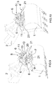
- the figures 2 , 9 and 10 show more precisely the quick coupler assembly 3, the tool 1 being being connected to the arm 2.
- the hooks 7 are located at the rear of the coupler 5 and are open to the opposite of the machine; they are caught on the pins 8 of the connection device 4.
- the interface 9 of the connection device 4 is located in front of the pins 8 and comprises a functional face 20, directed forwardly.
- the face 20 may be substantially planar.
- the face 20 of the interface 9 is functionally complementary to the face 18 of the locking means 13.
- the interface 9 may further comprise notches 21 intended to receive the bar 11 in support.
- locking means 13 is biased towards its engaged position by return means, here comprising two torsion springs 22.
- the secure connection system 10 further comprises a safety member 25, more particularly illustrated on the figure 6 .
- the safety member 25 comprises, at its front portion, a through hole 26 in which is fixedly engaged a rod 27 of substantially transverse axis 28.
- the rod 27 is rotatably mounted in bearings 29 of the coupler 5 (see FIG. figure 3 and 4 ), and comprises two flats 30.
- Each of the bearings 29 comprises a housing in which is engaged a compression spring 32 whose upper end bears on one of the flats 30.
- the safety member 25 is biased from its deactivated position to its position activated by the springs 32, through the flats 30 and the rod 27.
- the safety member 25 has a substantially flat bottom face 33 and a stop face 34 which is substantially transverse and perpendicular to the lower face 33 and which faces towards the rear. Above the stop face 34, the safety member 25 has a rear part raised in the shape of a beak 35. The safety member 25 is further delimited by two lateral faces 36 substantially perpendicular to the Y axis. In the junction area between the lower face 33 and the stop face 34, the safety member 25 has a contact face 37. In the embodiment shown, the contact face 37 forms a chamfer. Alternatively, the contact face 37 could be rounded or have a cam-like profile, and / or not extend over the entire transverse dimension of the security member 25.
- the detection means 40 is rotatably mounted on a shaft 41 of substantially transverse axis 42 fixed to the flanges 6.
- the detection means 40 is disposed at the rear of the locking means 13 and the safety member 25. It is biased by return means 43 to its armed position, and can be moved, under the action of the connecting device 4 during connection and against said biasing means 43, to its disarmed position.
- the detection means 40 may for example be in the form of a finger.
- the secure connection system 10 comprises a release member designed to release the connection device 4 from the coupler 5.
- the release member is in the form of a key 45 illustrated on the figure 8 .
- the key 45 comprises a handle 46 on which the operator will be able to press to rotate the key 45 from a first position - high - to a second position - low, about a substantially transverse axis.
- the upper face of the nose 49 forms a convex contact face 50.
- the contact face 50 of the key is intended to cooperate with the contact face 37 of the safety member 25, for the release of the tool 1.
- the coupler 5 is tilted relative to the tool 1, so that the bar 11 approaches the interface 9 ( figure 9 then figure 10 ).
- the quick coupler assembly 3 is in the position shown in FIG. figure 11 .
- the detecting means 40 is in its armed position, and its front end forms a lug which is engaged and retained in the recess 19 of the locking means 13. As a result, the detecting means 40 holds the locking means 13 in position. its disengaged position, against the springs 22 which urge the locking means 13 to its engaged position. Consequently, there exists under the coupler 5 a free space in which the interface 9 of the connection device 4 can be introduced.
- the functional face 18 is held substantially oriented towards the safety member 25. Under the action of the springs 32 urging the safety member 25 towards its activated position, the lower face 33 of the safety member 25 is held in position. pressing against the functional face 18 of the locking means 13, and the locking means 13 thus keeps the safety member 25 in its deactivated position. The functional face 18 thus forms a stop in the locked position, which keeps the safety member 25 in the deactivated position.
- connection device 4 comes into contact with the connection system 10. More precisely, as illustrated in FIG. figure 12 a part of the interface 9 - here a protuberance 56 formed above the functional face 20 - comes into contact with the detection means 40, on the lower face thereof, and tends to raise it against return means 43, to move it to its disarmed position. Prior to this step, the protrusion 56 may have caused a slight displacement of the locking means 13 to its disengaged position.
- the locking means 13 continues to keep the safety member 25 in the deactivated position, the safety member 25 being in abutment on the functional face 18. Then, as shown in FIG. figure 13 , the locking means 13 has reached a position where the lower face 33 of the safety member 25 is no longer abutted on the functional face 18: the safety member, which is no longer maintained, then switches to its activated position under the effect of the springs 32. The stop formed by the functional face 18 is thus in the unlocking position, allowing the movement of the safety member towards its activated position.
- the locking means 13 continues its movement until it reaches its engaged position, the safety member 25 reaching its activated position. In this position, illustrated on the figure 14 , the quick coupler assembly 3 and the secure connection system 10 are in the normal position of use.
- the functional faces 18 and 20 are in contact and ensure the retention of the tool 1 connected to the arm 2.
- the secure connection system 10 would prevent a total disengagement of the locking means 13.
- the stop face 34 of the safety member 25 cooperating with the front face 23 of the locking means 13 is able to hinder the movement of the locking means 13 to its disengaged position.
- This safety position where the faces 34, 23 are in contact, is illustrated on the figure 15 and corresponds to an intermediate position of the locking means 13.
- the clearance j is determined so that the overlap d between the functional faces 18 and 20 is sufficient to ensure the retention of the tool 1 safely.
- the intermediate position of the locking means 13 is the limit position beyond which the locking means 13 can not hold the tool 1.
- the quick coupler assembly 3 being in its normal position of use (illustrated in FIG. figure 14 ), the key 45 is inserted between the locking means 13 and the safety member 25, as shown in FIG. figure 16 .
- the pin 47 is engaged in the hole 16 of the locking means 13, then the operator presses the handle 46 to pivot the key 45 from its first position, or up position ( figure 16 ) at its second position, or down position ( figure 20 ).
- the rotation of the key 45 from its first position to its second position simultaneously causes the rotation of the locking means 13 towards its disengaged position and the rotation of the safety member 25 towards its deactivated position.
- the figure 17 illustrates a first phase of this double displacement.
- the various constituent elements of the secure connection system 10 - in particular the locking means 13, the safety member 25 and the key 45 - are designed and arranged so that, when the locking means 13 reaches its intermediate position, the safety member 25 is no longer in the activated position, which would cause a blockage of the system and prevent further movement of the key to result in the release of the tool 1.
- the safety member 25 Since the stop face 34 of the safety member 25 is no longer opposite the front face 23 of the locking means 13, the safety member 25 no longer impedes the further movement of the locking means 13 until 'to its disengaged position.
- the nose 49 is no longer in contact with the safety member 25.
- the safety member 25 is now retained in its deactivated position by the abutment contact of the lower faces 33 and functional 18.
- the means of detection 40 is in the armed position.
- the locking means 13 tends to be moved to its engaged position by the springs 22. This movement is prevented because the detection means 40 which is in the armed position and which is housed in the recess 19, as illustrated more precisely on the figure 21 . This ensures the maintenance of the locking means 13 in the disengaged position and, consequently, the holding of the safety member 25 in the deactivated position.
- the secure connection system 10 is then again in the position of the figure 11 , ready for connecting another tool 1.
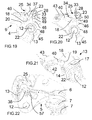
- the figure 22 illustrates more precisely a possible embodiment of the indication means 38 of the position of the safety member 25.
- the indicating means 38 not only have an orientation corresponding to that of the safety member 25, but in addition can be placed in alignment with a mark 57 formed on the coupler 5 when the safety member 25 is in the activated position - or in the deactivated position.
- the indicating means 38 consist of a shoulder forming a line, while the mark 57 consists of the edge of a relief formed on a flange 6, this is not limiting.
- FIG. 23 illustrate a secure connection system 110 and a coupler 105 according to a second embodiment of the invention.
- An element of the secure connection system 110 or the coupler 105 which is identical or corresponding, in structure or function, respectively to an element of the secure connection system 10 or the coupler 5, has the same numerical reference increased by 100.
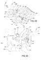
- the coupler 105 comprises two flanges 106, a single flange being represented on the figure 32 to facilitate understanding.
- the coupler 105 On each of its flanges 106, the coupler 105 comprises, at a first longitudinal end portion, a hook 107, here open towards the machine and, at a second longitudinal end portion, a notch 131, open downwards.
- the secure connection system 110 is mounted between the two flanges 106, in the vicinity of the notches 131.
- connection device 104 fixed on the tool 1 comprises a first axis 108 and a second axis 109 - which belongs to the interface - substantially transverse and parallel, intended to cooperate one with the hook 107, the other with the notch 131 of the coupler 105.
- the secure connection system 110 comprises a substantially cylindrical bar 111 of axis 112, arranged transversely and fixed to the flanges 106, at the second longitudinal end portion of the coupler 5.
- the locking means 113 On the bar 111 is mounted a locking means 113, which may be in the form of a part having side faces 160 substantially parallel to the flanges 106.
- the locking means 113 comprises a base 114 provided with an orifice 161 substantially transversely in which is engaged the bar 111.
- the base 114 is here located at a first end portion of the locking means 113 which, when the tool 1 is connected to the arm 2, is located substantially towards the front and towards the top of the coupler 105.
- the locking means 113 further includes a hook-shaped portion 163, generally at the second end portion of the locking means 113, opposite the base 114.
- a pin 164 extending substantially transversely from a side face 160 towards the flange 106 adjacent.
- the locking means 113 comprises, on its rear face - opposite to the opening of the hook 163 - on the one hand an oblique face 165 and on the other hand a notch extending the oblique face 165 in the direction of the base 114 and having a bottom face 166 and a locking face 167 substantially perpendicular to each other.
- the locking means 113 is biased towards its engaged position by return means, here comprising a spring 122.
- the secure connection system 110 further comprises a safety member 125.
- the safety member 125 comprises an annular base 170 integral with a rod 127 of substantially transverse axis 128.
- the rod 127 is rotatably mounted in bearings made in the flanges 106.
- the safety member 125 further comprises a substantially radial finger 171 having a stop face 134 and a locking face 172.
- these indicating means 138 are attached to one end of the rod 127, outside a flange 106. Being connected in rotation to the rod 127, itself rotatably connected to the safety member 125 these indicating means 138 may reflect the position of the security member 125 between its deactivated and activated positions.
- the safety member 125 is biased from its deactivated position to its activated position by a torsion spring 132.
- the detection means 140 is rotatably mounted about a substantially transverse axis 142 attached to the flanges 106, and disposed in front of the locking means 113. It has a recess 173 (see in particular the figure 24 ) open towards the rear, and intended to cooperate with the pin 164 as will be described later. It also comprises a lower face 182 intended to cooperate with the axis 109 of the connection device 104.
- the detection means 140 is biased by return means 143 towards its armed position, and can be moved, under the action of the connecting device 104 during connection and against said return means 143, to its position. disarmed.
- the secure connection system 110 comprises a lever 175 movable in rotation with respect to one of the components of the connection system 110 or with respect to the flanges 106, for example on the side of the locking means 113 opposite by means of 140.
- the lever 175 comprises, at the front, a flange having a front face 176 adapted to cooperate with the release means and a rear face 179 adapted to cooperate with the locking means 113.
- the lever further comprises a rear portion 177 adapted to cooperate with the security organ 125.
- the secure link system 110 also includes a release member configured to release the connection device 104 from the linkage system 110.
- this release member may be in the form of a hydraulic actuator 180 mounted on the secure connection system 110 or on the coupler 105 and can be moved from a retracted position ( figure 23 in particular) to a deployed position ( figure 28 especially).
- the hydraulic actuator 180 can be returned to its retracted position, for example by a return spring 181, as shown in FIG. figure 31 .
- the quick coupler assembly 103 is in the position shown in FIG. figure 23 .
- the detection means 140 is in its armed position, its lower face 182 being located at the right of the notch 131, that is to say lower than the bottom 183 of the notch 131.
- the recess 173 provided to the rear end of the detection means 140 cooperates with the pin 164 formed on the locking means 113. Accordingly, and because of the bias exerted by the spring 143, the detection means 140 maintains the locking means 113 in its position disengaged, against the spring 122 which urges the locking means 113 to its engaged position. There is thus under the coupler 105 a free space in which the axis 109 of the connection device 104 can be introduced.
- lever 175 is arranged so that its rear portion 177 is located - transversely - in correspondence with the notch of the locking means 113, and the rear face 179 of the flange is against the locking means 113.
- the coupler 105 is tilted with respect to the tool 1, so that the axis 109 enters the notch 131.
- the recess 173 no longer cooperates with the pin 164. It follows that the locking means 113, which is no longer held by the detection means 140, is moved, under the action of the spring 122, to its engaged position.
- the finger 171 of the safety member 125 moves, due to the spring 132, forwardly and along the oblique face 165 of the locking means 113, until reaching the notch. Once reached the notch, the safety member 125, which is no longer maintained, then switches to its activated position under the effect of the spring 132, the finger 171 being housed in the notch. The stop formed by the oblique face 165 is thus in the unlocking position, allowing the movement of the safety member towards its activated position.
- the figure 25 shows the quick coupler assembly 103 and the secure link system 110 in the normal position of use.
- the locking means 113 is in its engaged position, the axis 109 being held in the notch 131 by the hook 163, ensuring the retention of the tool 1 connected to the arm 2.
- the safety member 125 is in its position activated, housed in the notch of the locking means 113, the locking face 172 of the finger 171 being in contact with the locking face 167 of the notch of the locking means 113.
- the lever 175 since the lever 175 has been pushed by the finger 171 it is now placed so that its rear portion 177 is substantially in contact with the locking face 172 of the safety member.
- the secure connection system 110 would prevent a total disengagement of the means of disengagement. 113.
- the stop face 134 of the safety member 125 cooperating with the bottom face 166 of the notch of the locking means 113 is able to hinder the movement of the locking means 113 to its disengaged position.
- This safety position where the faces 134, 166 are in contact, is illustrated on the figure 26 , and corresponds to an intermediate position of the locking means 113.
- the game j is determined so that the recovery of figure 26 ) between the hook 163 and the axis 109 is sufficient to ensure the retention of the tool 1 safely.
- the hydraulic actuator 180 is moved to its deployed position, which leads to the movement of the lever 175 to an actuated position.
- the detection means under the action of the spring 143, returns to its armed position and maintains the locking means 113 in its disengaged position, via the pin 164 housed in the recess 173.
- the hydraulic actuator 180 can thus be returned to its retracted position ( figure 30 ), without this causing the locking means 113 to move towards its engaged position.
- the release member is therefore designed to cause, during its movement from its first position to its second position, sequentially the displacement of the safety member 125 towards its deactivated position and, once the safety member 125 is no longer in the activated position, the displacement of the locking means 113 towards its disengaged position.
- the key 145 is inserted in front of the locking means 113, as shown in FIG. figure 32 , so that the pin 116 of the locking means 113 is housed in the recess 178 and the nose 149 comes to bear with the front face 176 of the rim of the lever 175. Then the operator presses the handle 146 to rotate the key 145 from his first position to his second position.
- the key can be removably engaged with the safety member 125 and / or the frame of the coupler 105.
- an advantage of this second embodiment is that the release of the tool 1 can be obtained in two different ways, via a manual action on a key, or remotely via an action on a hydraulic actuator.
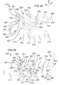
- Figures 34 to 46 illustrate a secure link system 210 and a coupler 205 according to a third embodiment of the invention.
- the secure link system 210 is described with reference to Figures 34 and 35 .
- the secure connection system 210 comprises a substantially cylindrical bar 211, of axis 212, arranged transversely and fixed to the flanges 206, to the second longitudinal end portion of the coupler 205.
- each of the transverse ends of the bar 211 can be mounted in an orifice formed in the corresponding flange 206.
- the locking means 213 comprises a substantially annular base 214, engaged on the bar 211, from which projects, towards the rear, a core 215 substantially flat and parallel to a plane (X, Z).
- the core 215 has at its front a hole 216.
- the locking means 213 further comprises a curved wall 217 located at the end of the core 215 opposite the base 214.
- the wall 217 has a convex functional face 218 .
- the wall 217 comprises a front face 223.
- the locking means 213 and the bar 211 are the main elements of the secure connection system 210 intended to cooperate with the interface 209 of the connection device 4 fixed to the tool 1.
- the figure 36 shows more precisely the quick coupling assembly 203, the tool 1 being being connected to the arm 2.
- the hooks 207 are located at the rear of the coupler 205 and are open to the opposite of the machine; they come to be caught on the pins 208 of the connection device 204.
- the interface 209 of the device of connection 204 is located at the front of the journals 208 and comprises a functional face 220, directed towards the front.
- the face 220 may be substantially flat.
- the face 220 of the interface 209 is functionally complementary to the face 218 of the locking means 213.
- the interface 209 may further comprise notches 221 intended to receive the bar 211 in support.
- the locking means 213 is biased towards its engaged position by return means, here comprising two torsion springs 222.
- the secure connection system 210 further comprises a security member 225.
- the safety member 225 comprises, at its front portion, a through hole 226 in which is fixedly engaged a rod 227 of axis 228 substantially transverse.
- the rod 227 is rotatably mounted in bearings 229 of the coupler 205 (see FIG. figures 34 and 36 ), and comprises two flats 230.
- Each of the bearings 229 comprises a housing in which is engaged a compression spring 232 whose upper end bears on one of the flats 230.
- the safety member 225 is biased from its deactivated position to its position activated by the springs 232, through the flats 230 and the rod 227.
- the safety member 225 has a substantially flat bottom face 233 and a stop face 234 which is substantially transverse and perpendicular to the bottom face 233 and which faces rearwards. Above the stop face 234, the safety member 225 has a rear part raised in the form of spout 235. The safety member 225 is further delimited by two lateral faces 236 substantially perpendicular to the Y axis. In the junction area between the lower face 233 and the stop face 234, the safety member 225 has a contact face 237. In the embodiment shown, the contact face 237 forms a chamfer. As a variant, the contact face 237 could be rounded or have a cam-type profile, and / or not extend over the entire transverse dimension of the safety member 225.
- the safety member 225 further includes a pin 251 located under the spout 235 and which projects laterally beyond a side face 236.
- these indication means 238 are attached to one end of the rod 227, outside a flange 206. Being connected in rotation to the rod 227, itself linked in rotation to the safety member 225, these indication means 238 may reflect the position of the security member 225 between its deactivated and activated positions.
- the detection means 240 is rotatably mounted on a rod 241 of substantially transverse axis 242 fixed to the flanges 206.
- the detection means 240 is disposed laterally by means 213 and the safety member 225, so as to cooperate with the pin 251 of the safety member 225, as shown in the figure 34 and 35 .
- the detection means 240 is biased by return means 243 towards its armed position, and can be moved, under the action of the connecting device 204 during connection and against said return means 243, to its position. disarmed.
- the detection means 240 may be in the form of a part having lateral faces 285 substantially parallel to the lateral faces 236 of the safety member 225. From the axis 242, the detection means 240 comprises a tail 286 directed rearward and an appendix 287 extending towards the safety member 225. The appendix 287 is provided with a notch 288 having a bottom face 289 and a locking face 290 substantially perpendicular to each other. The notch 288 is connected to the shank 286 by an oblique face 291.
- the return means 243 can be connected to the detection means 240 in an area opposite the shank 286 with respect to the axis 242.
- the secure connection system 210 comprises a release member designed to release the connection device 204 from the coupler 205.
- the release member is in the form of a key 245 illustrated on FIG. the figure 35 .
- the upper face of the nose 249 forms a convex contact face 250.
- the contact face 250 of the key is intended to cooperate with the contact face 237 of the safety member 225, for the release of the tool 1.
- the coupler 205 is tilted with respect to the tool 1, so that the bar 211 approaches the interface 209.
- the quick coupler 203 is in the position shown in FIG. figure 36 .
- the detection means 240 is in its armed position. In this position, the pin 251 of the security member 225 is housed in the notch 288 of the detection means 240, and more precisely rests on the bottom face 289. As a result, the detection means 240 maintains the safety member 225 in its deactivated position, against the springs 232 which urge the safety member 225 to its activated position. The bottom face 289 of the detection means 240 thus forms a stop in the locked position, which keeps the safety member 225 in the deactivated position.
- the locking means 213 is in its engaged position, due to the action exerted by the springs 222.
- connection device 204 comes into contact with the connection system 210. More precisely, as illustrated in FIG. figure 36 , a part of the interface 209 - here a protuberance 256 formed above the functional face 220 - comes into contact with the locking means 213, on the lower face of the wall 217, and tends to lift against return means 222, to move it to its disengaged position, as can be seen by comparing the Figures 36 and 37 .
- connection device 204 brings into contact a portion of the interface 209 - here a protuberance 256 'formed above the functional face 220 - with the detection means 240 ( figure 38 ).
- the detection means 240 is thus displaced, against the force exerted by the spring 243, towards its disarmed position.
- the bottom face 289 of the notch 288 moves under the pin 251 of the safety member 225.
- the pin 251 escapes the notch 288.
- the stop formed by the bottom face 289 occupies an unlocking position, and allows the movement of the safety member 225 to its activated position, under the effect of the springs 232.
- the lower face 233 of the safety member 225 abuts against the operative face 218 of the locking means 213, the safety member 225reste maintained in its disabled position ( figure 40 ).
- the figure 40 illustrates the end of the phase of the connection process of the tool 1 where the protuberance 256 is in contact with the locking means 213.
- the locking means 213 When the connection process of the tool 1 continues, the locking means 213 is no longer supported on the protrusion 256. Because of the springs 222, the locking means 213 switches to its engaged position, the functional faces 218 and 220 cooperating to ensure the retention of the tool 1 on the arm 2.
- the locking means 213 has reached a position where the lower face 233 of the safety member 225 no longer abuts on the functional face 218: the safety member, which is no longer maintained, then switches to its position activated by the effect of the springs 232.
- the stop formed by the functional face 218 is thus in the unlocking position, allowing the movement of the safety member towards its activated position.
- the detection means 240 remains in its disarmed position, resting on the protuberance 256 '.
- the quick coupling assembly 203 and the secure connection system 210 are then in the position illustrated on the figure 41 , which corresponds to the normal position of use.
- the functional faces 218, 220 are in contact and ensure the retention of the tool 1 connected to the arm 2.
- the secure connection system 210 would prevent a total disengagement of the locking means 213.
- the stop face 234 of the safety member 225 cooperating with the front face 223 of the locking means 213 is able to hinder the movement of the locking means 213 to its disengaged position.
- This safety position where the faces 234, 223 are in contact, is illustrated on the figure 42 , and corresponds to an intermediate position of the locking means 213.
- the clearance j is determined so that overlap d between the functional faces 218 and 220 is sufficient to ensure the retention of the tool 1 safely.
- the intermediate position of the locking means 213 is the limit position beyond which the locking means 213 can not hold the tool 1.
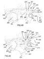
- the quick coupler 203 being in its normal position of use (illustrated in FIG. figure 41 key 245 is inserted between the locking means 213 and the safety member 225, as shown in FIG. figure 43 .
- the stud 247 is engaged in the hole 216 of the locking means 213, then the operator presses the handle 246 to pivot the key 245 from its first position, or up position ( figure 43 ) at its second position, or down position ( figure 45 ).
- the movement of the key 245 towards its second position causes the locking means 213 to move towards its disengaged position.
- the contact face 250 of the nose 249 of the key 245 comes into contact with the contact face 237 of the safety member 225 and lifts it to its deactivated position.
- the rotation of the key 245 from its first position to its second position simultaneously causes the locking means 213 to rotate to its disengaged position and the rotation of the safety member 225 to its deactivated position.
- the figure 43 illustrates a first phase of this double displacement.
- the various constituent elements of the secure connection system 210 - in particular the locking means 213, the safety member 225 and the key 245 - are designed and arranged so that, when the means the locking member 213 reaches its intermediate position, the safety member 225 is no longer in the activated position, which would cause a blockage of the system and prevent further movement of the key to result in the release of the tool 1.
- the specific shape of the protruding nose 249, the contact faces 237, 250 and the lower face 233 leads to a displacement of the safety member 225 to its deactivated position before the locking means 213, pulled towards its position disengaged by the pivoting of the key 245, does not reach its intermediate position.
- the stop face 234 of the safety member 225 is no longer opposite the front face 223 of the wall 217 of the locking means 213, the safety member 225 no longer hinders the further movement of the means. locking 213 to its disengaged position.
- the locking means 213 returns to its engaged position, under the effect of the springs 222 accompanied by the operator by means of the key 245.
- the invention is not limited to the presence of a single locking means and a single safety member.
Abstract
Le système de liaison sécurisée (10) comprend : - un moyen de verrouillage (13) sollicité d'une position désengagée à une position engagée dans laquelle il retient un outil ; - un organe de sécurité (25) sollicité d'une position désactivée, dans laquelle il n'entrave pas le déplacement du moyen de verrouillage, à une position activée, dans laquelle il limite le déplacement du moyen de verrouillage depuis sa position engagée jusqu'à une position intermédiaire au-delà de laquelle le moyen de verrouillage ne retient plus l'outil ; - un organe de libération de l'outil (45) provoquant le déplacement de l'organe de sécurité vers sa position désactivée et le déplacement du moyen de verrouillage vers sa position désengagée, de sorte que, lorsque le moyen de verrouillage atteint sa position intermédiaire, l'organe de sécurité ne soit plus en position activée.The secure link system (10) comprises: - Locking means (13) biased from a disengaged position to an engaged position in which it retains a tool; a safety member (25) biased from a deactivated position, in which it does not hinder the movement of the locking means, to an activated position, in which it limits the movement of the locking means from its engaged position to at an intermediate position beyond which the locking means no longer holds the tool; a tool release member (45) causing the safety member to move towards its deactivated position and the locking means to move towards its disengaged position, so that when the locking means reaches its intermediate position , the safety member is no longer in the activated position.
Description
La présente invention concerne un système de liaison sécurisée entre un outil et un bras d'un engin de travaux publics. L'invention concerne également un coupleur destiné à être monté à l'extrémité d'un bras d'un engin de travaux publics et comprenant un tel système, ainsi qu'un engin de travaux publics équipé d'un tel coupleur.The present invention relates to a secure connection system between a tool and an arm of a public works machine. The invention also relates to a coupler intended to be mounted at the end of an arm of a public works machine and comprising such a system, and a public works machine equipped with such a coupler.
Le système de liaison sécurisée selon l'invention est destiné à un ensemble d'attache rapide. Le principe général d'un ensemble d'attache rapide d'un outil sur l'extrémité d'un bras d'un engin de travaux public prévoit de doter l'outil d'un dispositif de connexion qui possède généralement des moyens de connexion mâles tels que des axes ou tourillons, et de doter l'extrémité du bras d'un coupleur qui possède des moyens de connexion femelles tels que des crochets sur lesquels s'engagent les moyens de connexion mâles.The secure connection system according to the invention is intended for a quick coupler assembly. The general principle of a quick attachment assembly of a tool on the end of an arm of a public works machine provides the tool with a connection device which usually has male connection means such as pins or pins, and provide the end of the arm of a coupler which has female connection means such as hooks on which engage the male connection means.
Un ensemble d'attache rapide de ce type est par exemple décrit dans le document
Un tel ensemble d'attache rapide permet de connecter un outil à un bras d'un engin sans intervention manuelle du conducteur de l'engin et assure de façon généralement satisfaisante la sécurité de la connexion.Such a quick coupler assembly makes it possible to connect a tool to an arm of a machine without manual intervention by the driver of the machine and generally satisfies the safety of the connection.
Toutefois, la libération de l'outil nécessite dans un premier temps la désactivation de l'organe de sécurité et dans un deuxième temps le désengagement du moyen de verrouillage. Ces deux actions, lorsqu'elles doivent être effectuées manuellement, nécessitent une gestuelle complexe et fastidieuse, et, lorsqu'elles doivent être effectuées hydrauliquement, nécessitent la mise en place de deux actionneurs dont l'ordre de fonctionnement doit être contrôlé.However, the release of the tool initially requires the deactivation of the safety member and in a second time the disengagement of the locking means. These two actions, when they must be carried out manually, require a complex and tedious gesture, and, when they must be performed hydraulically, require the establishment of two actuators whose operating order must be controlled.
Ainsi, avec ce type d'ensemble d'attache rapide, si la mise en place de l'outil est simple, en revanche la libération de l'outil est malaisée.Thus, with this type of quick coupler assembly, if the implementation of the tool is simple, however the release of the tool is difficult.
La présente invention vise à remédier aux inconvénients mentionnés ci-dessus.The present invention aims to overcome the disadvantages mentioned above.
A cet effet, et selon un premier aspect, l'invention concerne un système de liaison sécurisée pour un ensemble d'attache rapide comprenant un dispositif de connexion fixé sur un outil et un coupleur qui est monté à l'extrémité d'un bras d'un engin de travaux publics et qui est conçu pour se connecter au dispositif de connexion, le système de liaison sécurisée étant destiné à être monté sur le coupleur et à coopérer avec le dispositif de connexion, et comprenant :
- au moins un moyen de verrouillage sollicité par des moyens de rappel d'une position désengagée, dans laquelle, en fonctionnement, il autorise le déplacement du dispositif de connexion par rapport au coupleur, à une position engagée, dans laquelle il est apte à coopérer avec le dispositif de connexion pour assurer la retenue de l'outil ;
- au moins un organe de sécurité mobile entre une position désactivée, dans laquelle il n'entrave pas le déplacement du moyen de verrouillage entre ses positions engagée et désengagée, et une position activée, dans laquelle il limite le déplacement du moyen de verrouillage depuis sa position engagée jusqu'à une position intermédiaire au-delà de laquelle le moyen de verrouillage ne peut pas retenir l'outil, en fonctionnement ;
- un dispositif de libération de l'outil conçu pour libérer le dispositif de connexion du système de liaison.
- at least one locking means biased by return means of a disengaged position, in which, in operation, it authorizes the displacement of the connection device relative to the coupler, to an engaged position, in which it is able to cooperate with the connection device for holding the tool;
- at least one movable safety member between a deactivated position, in which it does not impede the displacement of the locking means between its engaged and disengaged positions, and an activated position, in which it limits the movement of the locking means from its position engaged to an intermediate position beyond which the locking means can not hold the tool, in operation;
- a tool release device adapted to release the connection device from the linkage system.
De plus, selon une définition générale de l'invention :
- le système de liaison comprend :
- des moyens de rappel qui sollicitent l'organe de sécurité de sa position désactivée vers sa position activée ;
- un moyen de détection de la présence d'un outil, qui est sollicité par des moyens de rappel vers une position armée et qui peut être déplacé, sous l'action du dispositif de connexion en cours de connexion et à l'encontre desdits moyens de rappel, vers une position désarmée ;
- et le dispositif de libération de l'outil comprend un organe de libération mobile conçu pour, lors d'un mouvement d'une première position à une deuxième position, provoquer à la fois le déplacement de l'organe de sécurité vers sa position désactivée, et le déplacement du moyen de verrouillage vers sa position désengagée, de telle façon que, lorsque le moyen de verrouillage atteint sa position intermédiaire, l'organe de sécurité ne soit plus en position activée.
- the linking system comprises:
- return means which urge the safety member from its deactivated position to its activated position;
- means for detecting the presence of a tool, which is biased by biasing means towards an armed position and which can be moved, under the action of the connecting device during connection and against said means of recall, to an unarmed position;
- and the tool release device comprises a movable release member adapted to, upon movement from a first position to a second position, causing both the movement of the safety member to its deactivated position, and moving the locking means to its disengaged position, such that when the locking means reaches its intermediate position, the safety member is no longer in the activated position.
Ainsi, en prévoyant un organe de libération agencé pour provoquer, en un seul et même mouvement, à la fois la désactivation de l'organe de sécurité et le désengagement du moyen de verrouillage, l'invention permet de simplifier considérablement le processus de libération de l'outil. La mise en oeuvre du système de liaison sécurisée s'en trouve plus pratique et moins fastidieuse. Par ailleurs, l'invention permet de conserver une connexion automatique de l'outil, sans intervention manuelle, au sol, d'un opérateur ou du conducteur de l'engin.Thus, by providing a release member arranged to cause, in one and the same movement, both the deactivation of the safety member and the disengagement of the locking means, the invention makes it possible to considerably simplify the process of releasing the the tool. The implementation of the secure link system is more convenient and less tedious. Moreover, the invention makes it possible to maintain an automatic connection of the tool, without manual intervention, on the ground, by an operator or the driver of the machine.
Un autre avantage de l'invention est d'améliorer encore la sécurisation de la liaison entre le coupleur - lié au bras de l'engin - et le dispositif de connexion - lié à l'outil - puisque l'organe de sécurité est toujours sollicité vers sa position activée.Another advantage of the invention is to further improve the securing of the connection between the coupler - linked to the arm of the machine - and the connection device - linked to the tool - since the safety member is always called upon to its activated position.
L'invention permet également d'obtenir une excellente stabilité du système, à la fois en position engagée et désengagée du moyen de verrouillage.The invention also makes it possible to obtain excellent stability of the system, both in the engaged and disengaged position of the locking means.
En position armée, le moyen de détection est en attente de l'outil et prêt à être désarmé.In the armed position, the detection means is waiting for the tool and ready to be disarmed.
En pratique, les moyens de rappel peuvent solliciter le moyen de verrouillage de la position désengagée à la position engagée sur l'ensemble de la course du moyen de verrouillage entre ces deux positions. Lesdits moyens de rappel peuvent être fixés sur le moyen de verrouillage.In practice, the return means can urge the locking means from the disengaged position to the position engaged over the entire stroke of the locking means between these two positions. Said return means can be fixed on the locking means.
Par ailleurs, on peut prévoir que les moyens de rappel sollicitant le moyen de verrouillage et les moyens de rappel sollicitant le moyen de détection soient distincts, c'est-à-dire que le moyen de détection soit sollicité vers une position indépendamment du moyen de verrouillage.Furthermore, it can be provided that the biasing means biasing the locking means and the biasing means biasing the detection means are distinct, that is to say that the detection means is biased towards a position independently of the means of locking.
En pratique, la position intermédiaire est distincte de la position engagée.In practice, the intermediate position is distinct from the engaged position.
Le système de liaison sécurisée peut en outre comprendre une butée qui peut occuper une position de blocage dans laquelle elle maintient l'organe de sécurité en position désactivée, et une position de déblocage dans laquelle elle autorise le déplacement de l'organe de sécurité vers sa position activée.The secure connection system may further comprise a stop which can occupy a locking position in which it keeps the safety member in the deactivated position, and an unlocking position in which it allows the movement of the safety member towards its position. activated position.
La butée permet de faciliter la connexion de l'outil car, lorsqu'elle est en position de blocage, elle évite que l'opérateur maintienne manuellement l'organe de sécurité en position désactivée, ce qui s'avèrerait nécessaire puisque cet organe de sécurité est sollicité vers sa position activée. Par ailleurs, la butée occupe sa position débloquée au moins lorsque l'outil est connecté, de façon à autoriser la sécurisation de la connexion.The stop facilitates the connection of the tool because, when in the locking position, it prevents the operator manually maintain the safety member in the deactivated position, which would be necessary since this safety member is biased to its activated position. By elsewhere, the stop occupies its unlocked position at least when the tool is connected, so as to allow the connection to be secured.
La butée précitée peut être constituée par l'un des éléments constitutifs du système selon l'invention, par exemple par le moyen de verrouillage ou par le moyen de détection.The abutment may be constituted by one of the constituent elements of the system according to the invention, for example by the locking means or by the detection means.
Avantageusement, le système de liaison sécurisée peut être conçu pour que, lorsque le moyen de détection est en position armée, l'organe de sécurité soit maintenu dans sa position désactivée. Ce maintien peut être obtenu soit directement, le moyen de détection formant la butée et maintenant lui-même l'organe de sécurité, soit indirectement, le moyen de détection maintenant le moyen de verrouillage qui forme la butée et qui maintient l'organe de sécurité.Advantageously, the secure connection system can be designed so that, when the detection means is in the armed position, the safety member is kept in its deactivated position. This holding can be obtained either directly, the detection means forming the abutment and now itself the safety member, or indirectly, the detecting means holding the locking means which forms the abutment and which holds the safety member .
Le moyen de détection est par exemple conçu pour maintenir la butée en position de blocage lorsqu'il est en position armée.The detection means is for example designed to maintain the stop in the locked position when in the armed position.
Le système de liaison selon l'invention peut prévoir que l'organe de sécurité soit maintenu en position désactivée au début du processus de connexion de l'outil, puis bascule brusquement vers sa position activée. Ainsi, l'organe de sécurité ne peut pas s'activer dès le début du processus de connexion.The connection system according to the invention can provide that the safety member is kept in the deactivated position at the beginning of the connection process of the tool, then suddenly switches to its activated position. Thus, the security organ can not be activated from the beginning of the connection process.
Selon une réalisation possible, le moyen de verrouillage est mobile en rotation entre ses positions engagée et désengagée.According to one possible embodiment, the locking means is rotatable between its engaged and disengaged positions.
Par exemple, le moyen de verrouillage, l'organe de sécurité et le moyen de détection sont mobiles en rotation entre leurs positions désengagée et engagée, désactivée et activée, armée et désarmée, respectivement, autour d'axes sensiblement parallèles.For example, the locking means, the safety member and the detecting means are rotatable between their disengaged and engaged, deactivated and activated positions, armed and disarmed, respectively, about substantially parallel axes.
Dans ce cas, on peut en outre prévoir que l'organe de libération soit mobile en rotation entre ses première et deuxième positions, autour d'un axe sensiblement parallèle aux axes de rotation du moyen de verrouillage, de l'organe de sécurité, et du moyen de détection.In this case, it can further be provided that the release member is rotatable between its first and second positions, about an axis substantially parallel to the axes of rotation of the locking means, of the safety member, and detection means.
Selon un mode de réalisation, la butée est constituée par une portion du moyen de verrouillage, le moyen de verrouillage étant conçu pour, lorsqu'il est en position désengagée, maintenir l'organe de sécurité en position désactivée. De préférence, le moyen de verrouillage peut être conçu pour maintenir l'organe de sécurité en position désactivée lorsque le moyen de verrouillage est entre sa position désengagée et sa position intermédiaire.According to one embodiment, the stop is constituted by a portion of the locking means, the locking means being adapted to, when in the disengaged position, keep the safety member in the deactivated position. Preferably, the locking means may be adapted to maintain the safety member in the deactivated position when the locking means is between its disengaged position and its intermediate position.
Le moyen de détection peut être conçu pour, lorsqu'il est en position armée, maintenir le moyen de verrouillage en position désengagée. Ainsi, on a un maintien indirect de l'organe de sécurité dans sa position désactivée, puisque le moyen de détection maintient le moyen de verrouillage, ce dernier formant la butée qui maintient l'organe de sécurité. L'avantage de maintenir le moyen de verrouillage en position désengagée lorsque le moyen de détection est en position armée est que le moyen de verrouillage n'occupe pas l'espace dans lequel l'outil va être engagé, et qu'il n'est donc pas nécessaire, préalablement à l'engagement de l'outil, de déplacer le moyen de verrouillage.The detection means may be designed to, when in the armed position, keep the locking means in the disengaged position. Thus, there is an indirect holding of the safety member in its deactivated position, since the detection means maintains the locking means, the latter forming the stop which holds the safety member. The advantage of keeping the locking means in the disengaged position when the detection means is in the armed position is that the locking means does not occupy the space in which the tool is going to be engaged, and that it is not therefore not necessary, prior to the engagement of the tool, to move the locking means.
Par exemple, le moyen de verrouillage et le moyen de détection comprennent l'un un ergot et l'autre un évidement, l'ergot étant conçu pour pouvoir se loger dans l'évidement de sorte que le moyen de détection puisse maintenir le moyen de verrouillage en position désengagée.For example, the locking means and the detecting means comprise a pin and the other a recess, the pin being designed to be able to fit in the recess so that the detection means can maintain the means of detection. lock in disengaged position.
Selon un autre mode de réalisation, la butée est constituée par une portion du moyen de détection, le moyen de détection étant conçu pour, lorsqu'il est en position armée, maintenir l'organe de sécurité en position désactivée. Ainsi, on a un maintien direct de l'organe de sécurité dans sa position désactivée, puisque le moyen de détection forme la butée et maintient lui-même l'organe de sécurité.According to another embodiment, the stop is constituted by a portion of the detection means, the detection means being designed for, when in the armed position, keep the safety member in the off position. Thus, there is a direct maintenance of the safety member in its deactivated position, since the detection means forms the stop and maintains itself the safety member.
Selon un mode de réalisation, l'organe de libération est conçu pour provoquer, lors de son mouvement de sa première position à sa deuxième position, simultanément le déplacement de l'organe de sécurité vers sa position désactivée et le déplacement du moyen de verrouillage vers sa position désengagée. Dans ce cas, les formes et agencements relatifs de l'organe de sécurité et du moyen de verrouillage sont conçus pour que, quand le moyen de verrouillage atteint sa position intermédiaire, l'organe de sécurité ne soit plus en position activée. La simultanéité desdits déplacements peut avoir lieu sur l'intégralité du mouvement de l'organe de libération de sa première position à sa deuxième position ou sur une partie seulement de ce mouvement.According to one embodiment, the release member is adapted to cause, during its movement from its first position to its second position, simultaneously the movement of the safety member towards its deactivated position and the movement of the locking means towards his position disengaged. In this case, the relative shapes and arrangements of the safety member and the locking means are designed so that when the locking means reaches its intermediate position, the safety member is no longer in the activated position. The simultaneity of said displacements can take place on the entire movement of the release member from its first position to its second position or only part of this movement.
Selon un autre mode de réalisation, l'organe de libération est conçu pour provoquer, lors de son mouvement de sa première position à sa deuxième position, séquentiellement le déplacement de l'organe de sécurité vers sa position désactivée puis, une fois que l'organe de sécurité n'est plus en position activée, le déplacement du moyen de verrouillage vers sa position désengagée. En d'autres termes, les déplacements de l'organe de sécurité et du moyen de verrouillage ne sont pas simultanés mais successifs, au moins dans une première phase du mouvement de l'organe de libération de sa première position à sa deuxième position. Il est à noter qu'il n'est pas nécessaire que l'organe de sécurité soit en position désactivée pour que le moyen de verrouillage puisse commencer à être déplacé. L'important est que l'organe de sécurité ne soit plus en position activée quand le moyen de verrouillage est en position intermédiaire, afin de ne pas empêcher la poursuite de son déplacement.According to another embodiment, the release member is designed to cause, during its movement from its first position to its second position, sequentially the movement of the safety member towards its deactivated position and then, once the safety member is no longer in the activated position, the displacement of the locking means towards its disengaged position. In other words, the movements of the security organ and locking means are not simultaneous but successive, at least in a first phase of the movement of the release member from its first position to its second position. It should be noted that it is not necessary that the safety member is in the deactivated position so that the locking means can begin to be moved. The important thing is that the safety member is no longer in the activated position when the locking means is in the intermediate position, so as not to prevent further movement.
Selon un mode de réalisation, l'organe de libération est conçu pour, lors de son mouvement de sa première position à sa deuxième position, venir en contact d'une part avec l'organe de sécurité et d'autre part avec le moyen de verrouillage pour provoquer leurs déplacements. En d'autres termes, l'organe de libération agit directement sur l'organe de sécurité et sur le moyen de verrouillage.According to one embodiment, the release member is designed, when moving from its first position to its second position, to come into contact on the one hand with the safety member and on the other hand with the means of locking to cause their movements. In other words, the release member acts directly on the safety member and on the locking means.
Selon un autre mode de réalisation, l'organe de libération est conçu pour, lors de son mouvement de sa première position à sa deuxième position, venir en contact avec un levier mobile et provoquer le déplacement de ce levier d'une position d'attente à une position d'actionnement, le levier étant conçu pour, lorsqu'il est ainsi déplacé, venir en contact d'une part avec l'organe de sécurité et d'autre part avec le moyen de verrouillage pour provoquer leurs déplacements. En d'autres termes, l'organe de libération agit indirectement sur l'organe de sécurité et sur le moyen de verrouillage, via un levier intermédiaire.According to another embodiment, the release member is designed, when moving from its first position to its second position, to come into contact with a movable lever and to cause this lever to move from a waiting position. an actuating position, the lever being designed to, when so moved, come into contact on the one hand with the safety member and on the other hand with the locking means to cause their movements. In other words, the release member acts indirectly on the safety member and on the locking means via an intermediate lever.
Selon un mode de réalisation, l'organe de libération est constitué d'une clé amovible conçue pour être déplacée manuellement par un opérateur de sa première position à sa deuxième position. Typiquement, la clé peut être mise en prise, de façon amovible, avec le moyen de verrouillage et/ou l'organe de sécurité et/ou le bâti du coupleur. L'action de libération réalisée par la clé sur le système de liaison sécurisée peut être obtenue de façon directe, ou de façon indirecte - c'est-à-dire via une pièce intermédiaire.According to one embodiment, the release member consists of a removable key adapted to be moved manually by an operator from its first position to its second position. Typically, the key can be releasably engaged with the locking means and / or the safety member and / or the coupler frame. The release action performed by the key on the secure connection system can be obtained directly, or indirectly - that is via an intermediate part.
On peut prévoir que la clé comporte une face de contact ménagée sur un nez en saillie et destinée à coopérer avec une face de contact correspondante - généralement arrondie ou oblique - ménagée sur l'organe de sécurité, la clé et les faces de contact étant agencées pour que la rotation de la clé de sa première position à sa deuxième position provoque la rotation de l'organe de sécurité vers sa position désactivée. En outre, la clé peut comporter un moyen d'assemblage temporaire au moyen de verrouillage, de sorte que la rotation de la clé de sa première position à sa deuxième position provoque simultanément la rotation du moyen de verrouillage vers sa position désengagée et la rotation de l'organe de sécurité vers sa position désactivée.It can be provided that the key comprises a contact face formed on a projecting nose and intended to cooperate with a corresponding contact face - generally rounded or oblique - arranged on the safety member, the key and the contact faces being arranged for the rotation of the key from its first position to its second position causes the rotation of the safety member to its deactivated position. In addition, the key may comprise a means of temporary assembly by means of locking, so that the rotation of the key from its first position to its second position simultaneously causes the rotation of the locking means to its disengaged position and the rotation of the safety member to its deactivated position.
En variante et/ou en complément, l'organe de libération peut comprendre un actionneur hydraulique monté de façon permanente sur le système de liaison, ou destiné à être monté de façon permanente sur le coupleur, l'actionneur pouvant être déplacé de sa première position, ou position rétractée, à sa deuxième position, ou position déployée, et pouvant être ramené à sa première position. L'actionneur hydraulique peut typiquement être déplacé par des moyens de commande à distance, comme un bouton disposé dans la cabine de l'engin actionnable par le conducteur. Pour le rappel de l'actionneur à sa première position, on peut prévoir qu'il soit sollicité par des moyens de rappel, ou qu'il consiste en un vérin double effet.As a variant and / or in addition, the release member may comprise a hydraulic actuator permanently mounted on the connection system, or intended to be permanently mounted on the coupler, the actuator being able to be moved from its first position , or retracted position, in its second position, or deployed position, and can be returned to its first position. The hydraulic actuator can typically be moved by remote control means, such as a button disposed in the cab of the machine operable by the driver. For the recall of the actuator in its first position, it can be provided that it is biased by biasing means, or that it consists of a double-acting cylinder.
Le système de liaison sécurisée peut en outre comprendre des moyens d'indication de la position de l'organe de sécurité, visibles par le conducteur de l'engin, depuis la cabine. Ces moyens d'indication peuvent typiquement être liés mécaniquement à l'organe de sécurité pour être animés simultanément du même mouvement. La visibilité de la bonne position de l'organe de sécurité assure au conducteur que le système de liaison a fonctionné correctement. En d'autres termes, la bonne position des moyens d'indication assure que les moyens de verrouillage sont engagés et que l'organe de sécurité est activé.The secure connection system may further comprise means for indicating the position of the safety member, visible by the driver of the machine, from the cabin. These indication means can typically be mechanically linked to the safety member to be simultaneously animated the same movement. The visibility of the correct position of the safety device ensures the driver that the connection system has worked properly. In other words, the good position of the indicating means ensures that the locking means are engaged and that the safety member is activated.
Selon un deuxième aspect, l'invention concerne un coupleur destiné à être monté à l'extrémité d'un bras d'un engin de travaux publics et conçu pour se connecter à un dispositif de connexion fixé sur un outil, le coupleur comprenant un système de liaison sécurisée tel que précédemment décrit.According to a second aspect, the invention relates to a coupler intended to be mounted at the end of an arm of a public works machine and designed to connect to a connection device attached to a tool, the coupler comprising a system secure link as previously described.
Selon un mode de réalisation, ce coupleur peut comprendre un ou deux crochet(s) destiné(s) à coopérer avec un ou deux tourillons du dispositif de connexion, tandis que le moyen de verrouillage possède une face courbe convexe configurée pour venir coopérer par appui avec une face complémentaire ménagée sur le dispositif de connexion, en fonctionnement et lorsque les moyens de verrouillage sont en position engagée.According to one embodiment, this coupler may comprise one or two hooks intended to cooperate with one or two journals of the connection device, while the locking means has a convex curved face configured to cooperate by support. with a complementary face provided on the connection device, in operation and when the locking means are in the engaged position.
Selon un autre mode de réalisation, ce coupleur peut comprendre un crochet destiné à coopérer avec un premier axe du dispositif de connexion et une encoche destiné à recevoir un deuxième axe du dispositif de connexion, tandis que le moyen de verrouillage se présente sous la forme d'un crochet mobile qui, dans sa position engagée, est apte à fermer l'encoche pour emprisonner le deuxième axe du dispositif de connexion, en fonctionnement.According to another embodiment, this coupler may comprise a hook intended to cooperate with a first axis of the connection device and a notch intended to receive a second axis of the connection device, while the locking means is in the form of a movable hook which, in its engaged position, is adapted to close the notch to trap the second axis of the connection device, in operation.
Selon un troisième aspect, l'invention concerne un engin de travaux publics comprenant :
- un bras à l'extrémité duquel est monté un coupleur ;
- et un outil sur lequel est fixé un dispositif de connexion ;
- an arm at the end of which is mounted a coupler;
- and a tool on which is attached a connection device;
De plus, le coupleur peut présenter l'une ou l'autre des structures précitées.In addition, the coupler may have one or the other of the aforementioned structures.
On décrit à présent, à titre d'exemples non limitatifs, plusieurs modes de réalisation possibles de l'invention, en référence aux figures annexées :
- La
figure 1 est une vue du bras d'un engin de travaux publics sur lequel est connecté un outil, le bras étant équipé d'un coupleur comportant un système de liaison sécurisée selon l'invention ; - La
figure 2 est une vue similaire à lafigure 1 , pour un premier mode de réalisation de l'invention, l'outil étant en cours de connexion ; - La
figure 3 est une vue de dessous du coupleur de lafigure 2 , montrant le système de liaison sécurisée ; - Les
figures 4 illustrent le système de liaison sécurisée de laet 5figure 3 , respectivement en vue montée, en perspective, et en vue éclatée ; - Les
figures 6 à 8 sont des vues en perspective respectivement d'un organe de sécurité, d'un moyen de verrouillage et d'un organe de libération appartenant au système de liaison sécurisée de lafigure 3 ; - Les
figures 9 à 14 illustrent des étapes successives de connexion d'un outil sur le coupleur de lafigure 3 ; - La
figure 15 représente l'outil connecté au coupleur de lafigure 3 , dans une position de sécurité ; - Les
figures 16 à 20 illustrent des étapes successives de libération de l'outil connecté au coupleur de lafigure 3 ; - La
figure 21 est une vue de détail montrant le moyen de détection coopérant avec le moyen de verrouillage pour le maintenir en position désengagée ; - La
figure 22 est une vue de détail du coupleur de lafigure 3 , montrant des moyens d'indication de la position de l'organe de sécurité ; - Les
figures 23 à 25 illustrent des étapes successives de connexion d'un outil à un coupleur selon un deuxième mode de réalisation de l'invention ; - La
figure 26 représente l'outil connecté au coupleur desfigures 23 à 25 , dans une position de sécurité ; - Les
figures 27 à 30 illustrent des étapes successives de libération de l'outil connecté au coupleur desfigures 23 à 25 , selon une première variante ; - La
figure 31 est une vue de détail du coupleur de lafigure 30 , montrant un actionneur hydraulique ; - Les
figures 32 et 33 illustrent des étapes successives de libération de l'outil connecté au coupleur desfigures 23 à 25 , selon une deuxième variante ; - La
figure 34 est une vue en perspective d'un système de liaison sécurisée selon un troisième mode de réalisation de l'invention ; - La
figure 35 est une vue analogue à lafigure 34 , le système de liaison sécurisée étant représenté en éclaté ; - Les
figures 36 à 41 illustrent des étapes successives de connexion d'un outil au coupleur de lafigure 34 ; - La
figure 42 représente l'outil connecté au coupleur de lafigure 34 , dans une position de sécurité ; - Les
figures 43 à 46 illustrent des étapes successives de libération de l'outil connecté au coupleur de lafigure 34 . - La
figure 1 montre un outil 1 - ici un godet - connecté àun bras 2 d'un engin de travaux publics (non représenté) au moyen d'unensemble d'attache rapide 3. Cetensemble d'attache rapide 3 comporte :- un dispositif de connexion 4 fixé sur l'outil 1 ;
et un coupleur 5 qui est monté à l'extrémité dubras 2 et qui est conçu pour se connecter au dispositif deconnexion 4.
- The
figure 1 is a view of the arm of a public works machine on which is connected a tool, the arm being equipped with a coupler comprising a secure connection system according to the invention; - The
figure 2 is a view similar to thefigure 1 for a first embodiment of the invention, the tool being connected; - The
figure 3 is a bottom view of the coupler of thefigure 2 , showing the secure link system; - The
Figures 4 and 5 illustrate the secure link system of thefigure 3 respectively in a mounted view, in perspective, and in an exploded view; - The
Figures 6 to 8 are perspective views respectively of a safety member, a locking means and a release member belonging to the secure connection system of thefigure 3 ; - The
Figures 9 to 14 illustrate successive steps of connecting a tool on the coupler of thefigure 3 ; - The
figure 15 represents the tool connected to the coupler of thefigure 3 in a safety position; - The
Figures 16 to 20 illustrate successive steps of release of the tool connected to the coupler of thefigure 3 ; - The
figure 21 is a detail view showing the detecting means cooperating with the locking means to hold it in the disengaged position; - The
figure 22 is a detail view of the coupler of thefigure 3 , showing means for indicating the position of the safety member; - The
Figures 23 to 25 illustrate successive steps of connecting a tool to a coupler according to a second embodiment of the invention; - The
figure 26 represents the tool connected to the coupler of theFigures 23 to 25 in a safety position; - The
Figures 27 to 30 illustrate successive steps of release of the tool connected to the coupler of theFigures 23 to 25 according to a first variant; - The
figure 31 is a detail view of the coupler of thefigure 30 , showing a hydraulic actuator; - The
Figures 32 and 33 illustrate successive steps of release of the tool connected to the coupler of theFigures 23 to 25 according to a second variant; - The
figure 34 is a perspective view of a secure link system according to a third embodiment of the invention; - The
figure 35 is a view similar to thefigure 34 , the secure link system being shown exploded; - The
Figures 36 to 41 illustrate successive steps of connecting a tool to the coupler of thefigure 34 ; - The
figure 42 represents the tool connected to the coupler of thefigure 34 in a safety position; - The
Figures 43 to 46 illustrate successive steps of release of the tool connected to the coupler of thefigure 34 . - The
figure 1 shows a tool 1 - here a bucket - connected to anarm 2 of a public works machine (not shown) by means of aquick coupler assembly 3. Thisquick coupler assembly 3 comprises:- a
connection device 4 fixed on thetool 1; - and a
coupler 5 which is mounted at the end of thearm 2 and which is adapted to connect to theconnection device 4.
- a
De plus, un système de liaison sécurisée 10 selon l'invention est monté sur le coupleur 5 et est destiné à coopérer avec le dispositif de connexion 4, en position connectée de l'outil 1.In addition, a
Le coupleur 5 comprend généralement deux flasques 6 sensiblement parallèles et écartés l'un de l'autre suivant une direction transversale Y.The
On définit par ailleurs la direction longitudinale X comme la direction sensiblement horizontale et parallèle au plan moyen des flasques 6. Les termes « avant » et « arrière » seront utilisés en référence à la direction X et à un déplacement de l'engin en marche avant. On définit également la direction verticale Z, par rapport à laquelle seront utilisés les termes « supérieur », « inférieur » et analogue.Furthermore, the longitudinal direction X is defined as the substantially horizontal direction and parallel to the mean plane of the
On se rapporte tout d'abord aux
Dans ce mode de réalisation, le coupleur 5 comprend un crochet 7 ménagé sur chacun de ses flasques 6, à une première partie extrême longitudinale du coupleur 5. En outre, le système de liaison sécurisée 10 est monté entre les deux flasques 6, à la deuxième partie extrême longitudinale du coupleur 5.Quant au dispositif de connexion 4 fixé sur l'outil 1, il comprend d'une part deux tourillons 8 sensiblement transversaux et coaxiaux destinés à coopérer chacun avec un crochet 7, et d'autre part une interface 9 destinée à coopérer avec le système de liaison sécurisée 10.In this embodiment, the
Le système de liaison sécurisée 10 est décrit en référence aux
Le système de liaison sécurisée 10 comprend une barre 11 sensiblement cylindrique, d'axe 12, agencée transversalement et fixée aux flasques 6, à la deuxième partie extrême longitudinale du coupleur 5. En pratique, chacune des extrémités transversales de la barre 11 peut être montée dans un orifice ménagé dans le flasque 6 correspondant.The
Sur la barre 11 est monté un moyen de verrouillage 13, représenté plus spécifiquement sur la
Le moyen de verrouillage 13 comporte une base 14 sensiblement annulaire, engagée sur la barre 11, de laquelle fait saillie, vers l'arrière, uneâme 15 sensiblement plane et parallèle à un plan(X, Z). L'âme 15 possède à sa partie avant un orifice 16. Le moyen de verrouillage 13 comporte de plus une paroi 17 courbe située à l'extrémité de l'âme 15 opposée à la base 14. La paroi 17 présente une face fonctionnelle 18 convexe. Dans la paroi 17, et à la partie inférieure de celle-ci, est ménagé un évidement 19 ouvert vers l'arrière. En outre, la paroi 17 comprend une face avant 23.The locking means 13 comprises a substantially
Le moyen de verrouillage 13 et la barre 11 sont les principaux éléments du système de liaison sécurisée 10 destinés à coopérer avec l'interface 9 du dispositif de connexion 4 fixé sur l'outil 1.The locking means 13 and the
Les
En fonctionnement, le moyen de verrouillage 13 est mobile en rotation autour de la barre 11 entre :
- une position engagée - en pratique une position abaissée - dans laquelle les faces fonctionnelles 18 et 20 coopèrent par appui, de façon à assurer la retenue de l'outil 1 sur le
bras 2 ; - et une position désengagée- en pratique une position relevée - dans laquelle les faces fonctionnelles 18
et 20 ne coopèrent pas, le moyen de verrouillage 13 autorisant donc le déplacement du dispositif de connexion 4 parrapport au coupleur 5.
- a position engaged - in practice a lowered position - in which the functional faces 18 and 20 cooperate by support, so as to ensure the retention of the
tool 1 on thearm 2; - and a disengaged position - in practice a raised position - in which the functional faces 18 and 20 do not cooperate, the locking means 13 thus allowing the displacement of the
connection device 4 with respect to thecoupler 5.
De plus, le moyen de verrouillage 13 est sollicité vers sa position engagée par des moyens de rappel, comportant ici deux ressorts de torsion 22.In addition, the locking means 13 is biased towards its engaged position by return means, here comprising two torsion springs 22.
Le système de liaison sécurisée 10 comprend de plus un organe de sécurité 25, plus particulièrement illustré sur la
L'organe de sécurité 25 comporte, à sa partie avant, un orifice 26 traversant dans lequel est engagée de façon fixe une tige 27 d'axe 28 sensiblement transversal. La tige 27 est montée libre en rotation dans des paliers 29 du coupleur 5 (voir
L'organe de sécurité 25 est situé au-dessus du moyen de verrouillage 13 et est mobile en rotation, autour de l'axe 28, entre :
- une position désactivée - en pratique une position relevée - dans laquelle il n'entrave pas le déplacement du moyen de verrouillage 13 entre ses positions engagée et désengagée ;
- et une position activée - en pratique une position abaissée - dans laquelle il limite le déplacement du moyen de verrouillage 13 depuis sa position engagée jusqu'à une position intermédiaire au-delà de laquelle le moyen de verrouillage 13 ne peut pas retenir l'outil 1, en fonctionnement.
- a deactivated position - in practice a raised position - in which it does not interfere with the displacement of the locking means 13 between its engaged and disengaged positions;
- and an activated position - in practice a lowered position - in which it limits the displacement of the locking means 13 from its engaged position to an intermediate position beyond which the locking means 13 can not hold the
tool 1 , Operating.
De plus, l'organe de sécurité 25 est sollicité de sa position désactivée vers sa position activée par les ressorts 32, par le biais des méplats 30 et de la tige 27.In addition, the
L'organe de sécurité 25 présente une face inférieure 33 sensiblement plane et une face d'arrêt 34 qui est sensiblement transversale et perpendiculaire à la face inférieure 33 et qui est tournée vers l'arrière. Au-dessus de la face d'arrêt 34, l'organe de sécurité 25 possède une partie arrière relevée en forme de bec 35. L'organe de sécurité 25 est de plus délimité par deux faces latérales 36 sensiblement perpendiculaires à l'axe Y. Dans la zone de jonction entre la face inférieure 33 et la face d'arrêt 34, l'organe de sécurité 25 présente une face de contact 37. Dans la réalisation représentée, la face de contact 37 forme un chanfrein. En variante, la face de contact 37pourrait être arrondie ou avoir un profil de type came, et/ou ne pas s'étendre sur toute la dimension transversale de l'organe de sécurité 25.The
On peut de plus prévoir des moyens d'indication 38 de la position de l'organe de sécurité 25 qui soient aisément visibles par le conducteur de l'engin depuis la cabine, donc depuis l'extérieur du coupleur 5. Par exemple, dans la réalisation des
Le système de liaison sécurisée 10 comprend de plus un moyen de détection 40 de la présence d'un outil 1, qui est mobile entre :
- une position armée - en pratique une position abaissée - lorsqu'aucun outil 1 n'est connecté au coupleur 5 ;
- et une position désarmée - en pratique une position relevée.
- an armed position - in practice a lowered position - when no
tool 1 is connected to thecoupler 5; - and a disarmed position - in practice a raised position.
Dans la réalisation représentée, le moyen de détection 40 est monté rotatif sur une tige 41 d'axe 42 sensiblement transversal fixée aux flasques 6. Le moyen de détection 40 est disposé à l'arrière du moyen de verrouillage13 et de l'organe de sécurité 25. Il est sollicité par des moyens de rappel 43 vers sa position armée, et peut être déplacé, sous l'action du dispositif de connexion 4 en cours de connexion et à l'encontre desdits moyens de rappel 43, vers sa position désarmée. Le moyen de détection 40 peut par exemple se présenter sous la forme d'un doigt.In the embodiment shown, the detection means 40 is rotatably mounted on a
Par ailleurs, le système de liaison sécurisée 10 comprend un organe de libération conçu pour libérer le dispositif de connexion 4 du coupleur 5. Dans ce premier mode de réalisation, l'organe de libération se présente sous la forme d'une clé 45 illustrée sur la
La clé 45 comprend un manche 46 sur lequel l'opérateur va pouvoir appuyer pour faire pivoter la clé 45 d'une première position - haute - à une deuxième position - basse, autour d'un axe sensiblement transversal.The key 45 comprises a
A sa partie extrême arrière, en fonctionnement, la clé 45 comporte :
un téton 47 d'axe 44sensiblement transversal, qui peut être engagé dans l'orifice 16 du moyen de verrouillage 13, formant ainsi un moyen d'assemblage temporaire au moyen de verrouillage 13 ;une face d'appui 48 incurvée tournée vers l'arrière ;- et un nez 49 en saillie vers le haut.
- a
pin 44 with a substantiallytransverse axis 44, which can be engaged in theorifice 16 of the locking means 13, thus forming a temporary assembly means for the locking means 13; - a bearing
surface 48 curved facing back; - and a
nose 49 projecting upwards.
La face supérieure du nez 49 forme une face de contact 50 convexe. Comme on le verra plus loin, la face de contact 50 de la clé est destinée à coopérer avec la face de contact 37 de l'organe de sécurité 25, pour la libération de l'outil 1.The upper face of the
On décrit à présent le processus de connexion d'un outil 1 au coupleur 5 en référence aux
Une fois les crochets 7 engagés autour des tourillons 8, le coupleur 5 est basculé par rapport à l'outil 1, de sorte que la barre 11 se rapproche de l'interface 9 (
Avant que l'interface 9 et le système de liaison sécurisée 10 n'interagissent, l'ensemble d'attache rapide 3 est dans la position illustrée sur la
Le moyen de détection 40 est dans sa position armée, et son extrémité avant forme un ergot qui est engagé et retenu dans l'évidement 19 du moyen de verrouillage 13. De ce fait, le moyen de détection 40 maintient le moyen de verrouillage 13 dans sa position désengagée, à l'encontre des ressorts 22 qui sollicitent le moyen de verrouillage 13 vers sa position engagée. En conséquence, il existe sous le coupleur 5 un espace libre dans lequel l'interface 9 du dispositif de connexion 4 peut être introduite.The detecting means 40 is in its armed position, and its front end forms a lug which is engaged and retained in the
En outre, dans la position de la
L'outil 1 et le dispositif de connexion 4 se rapprochant du coupleur 5, le dispositif de connexion 4 vient en contact avec le système de liaison 10. Plus précisément, comme illustré sur la
Le déplacement du moyen de détection 40 vers sa position désarmée conduit à sa sortie hors de l'évidement 19 ménagé sur le moyen de verrouillage 13. Il s'ensuit que le moyen de verrouillage 13, qui n'est plus retenu par le moyen de détection 40, est déplacé, sous l'action des ressorts de torsion 22, vers sa position engagée.The displacement of the detection means 40 towards its disarmed position leads to its exit from the
Au cours d'une première phase de ce déplacement, le moyen de verrouillage 13 continue de maintenir l'organe de sécurité 25 en position désactivée, l'organe de sécurité 25 étant en appui sur la face fonctionnelle 18. Puis, comme illustré sur la
Le moyen de verrouillage 13 continue son déplacement jusqu'à arriver à sa position engagée, l'organe de sécurité 25 atteignant sa position activée. Dans cette position, illustrée sur la
Dans l'hypothèse où le moyen de verrouillage 13 serait déplacé vers sa position désengagée, au cours des opérations de travail, le système de liaison sécurisée 10 empêcherait un désengagement total du moyen de verrouillage 13. En effet, la face d'arrêt 34 de l'organe de sécurité 25 coopérant avec la face avant 23 du moyen de verrouillage 13 est apte à entraver le déplacement du moyen de verrouillage 13vers sa position désengagée. Cette position de sécurité, où les faces 34, 23 sont en contact, est illustrée sur la
On décrit à présent, en référence aux
L'ensemble d'attache rapide 3 étant dans sa position normale d'utilisation (illustrée sur la
Le téton 47 est engagé dans l'orifice 16 du moyen de verrouillage 13, puis l'opérateur appuie sur le manche 46 pour faire pivoter la clé 45 de sa première position, ou position haute (
Du fait du téton 47 engagé dans l'orifice 16, le mouvement de la clé 45 vers sa deuxième position provoque le déplacement du moyen de verrouillage 13 vers sa position désengagée. De plus, au cours de ce mouvement, la face de contact 50 du nez 49 de la clé 45 vient en contact avec la face de contact 37 de l'organe de sécurité 25 et le soulève vers sa position désactivée.Due to the
Dans ce mode de réalisation, la rotation de la clé 45 de sa première position à sa deuxième position provoque simultanément la rotation du moyen de verrouillage 13 vers sa position désengagée et la rotation de l'organe de sécurité 25 vers sa position désactivée.In this embodiment, the rotation of the key 45 from its first position to its second position simultaneously causes the rotation of the locking means 13 towards its disengaged position and the rotation of the
La
Les différents éléments constitutifs du système de liaison sécurisée 10 - en particulier le moyen de verrouillage 13, l'organe de sécurité 25 et la clé 45 - sont conçus et agencés pour que, lorsque le moyen de verrouillage 13 atteint sa position intermédiaire, l'organe de sécurité 25 ne soit plus en position activée, ce qui occasionnerait un blocage du système et empêcherait la poursuite du mouvement de la clé pour aboutir à la libération de l'outil 1.The various constituent elements of the secure connection system 10 - in particular the locking means 13, the
Ainsi, comme illustré sur la
La face d'arrêt 34 de l'organe de sécurité 25 ne se trouvant plus en regard de la face avant 23 du moyen de verrouillage 13, l'organe de sécurité 25 n'entrave plus la poursuite du déplacement du moyen de verrouillage 13 jusqu'à sa position désengagée.Since the
Lors de la poursuite du pivotement de la clé 45 vers sa deuxième position, comme illustré sur la
Lorsque la clé 45 est dans sa deuxième position, comme illustré sur la
Une fois le téton 47 de la clé 46 désengagé de l'orifice 16, le moyen de verrouillage 13 tend à être déplacé vers sa position engagée par les ressorts 22. Mais ce déplacement est empêché car le moyen de détection 40 qui est en position armée et qui vient se loger dans l'évidement 19, comme illustré plus précisément sur la
La
On se rapporte à présent aux
Un élément du système de liaison sécurisée 110 ou du coupleur 105 identique ou correspondant, par sa structure ou par sa fonction, respectivement à un élément du système de liaison sécurisée 10 ou du coupleur 5, porte la même référence numérique augmentée de 100.An element of the
On définit ainsi un ensemble d'attache rapide 103 qui comporte :
- un dispositif de connexion 104 fixé sur l'outil 1 ;
et un coupleur 105 qui est monté à l'extrémité dubras 2 et qui est conçu pour se connecter au dispositif de connexion 104.
- a
connection device 104 fixed on thetool 1; - and a
coupler 105 which is mounted at the end of thearm 2 and which is adapted to connect to theconnection device 104.
Le coupleur 105 comprend deux flasques 106, un seul flasque étant représenté sur la
Sur chacun de ses flasques 106, le coupleur 105 comprend, à une première partie extrême longitudinale, un crochet 107, ici ouvert vers l'engin et, à une deuxième partie extrême longitudinale, une encoche 131, ouverte vers le bas. Le système de liaison sécurisée 110 est monté entre les deux flasques 106, au voisinage des encoches 131.On each of its
Le dispositif de connexion 104 fixé sur l'outil 1 comprend un premier axe108 et un deuxième axe 109 - qui appartient à l'interface - sensiblement transversaux et parallèles, destinés à coopérer l'un avec le crochet 107, l'autre avec l'encoche 131 du coupleur 105.The
Comme illustré sur les
Sur la barre 111 est monté un moyen de verrouillage 113, qui peut se présenter sous la forme d'une pièce possédant des faces latérales 160 sensiblement parallèles aux flasques 106. Le moyen de verrouillage 113 comprend une base 114 pourvue d'un orifice 161 sensiblement transversal dans lequel est engagée la barre 111. La base 114 est ici située à une première partie extrême du moyen de verrouillage 113 qui, lorsque l'outil 1 est connecté au bras 2, est située sensiblement vers l'avant et vers le haut du coupleur 105.On the
De la base 114 peut faire saillie, sensiblement vers l'avant, un bec 162duquel fait saillie un pion 116 sensiblement transversal. Le moyen de verrouillage 113 comporte de plus une partie en forme de crochet163, généralement à la deuxième partie extrême du moyen de verrouillage 113, opposée à la base 114.From the base 114 can project, substantially forwards, a
Sur le moyen de verrouillage 113, ici entre la base 114 et le crochet 163, est agencé un pion 164 s'étendant sensiblement transversalement depuis une face latérale 160 en direction du flasque 106 adjacent.On the locking means 113, here between the base 114 and the
Par ailleurs, le moyen de verrouillage 113 comprend, sur sa face arrière - opposée à l'ouverture du crochet 163 - d'une part une face oblique 165 et d'autre part un cran prolongeant la face oblique 165 en direction de la base 114 et présentant une face de fond 166 et une face de blocage 167 sensiblement perpendiculaire entre-elles.Furthermore, the locking means 113 comprises, on its rear face - opposite to the opening of the hook 163 - on the one hand an
En fonctionnement, le moyen de verrouillage 113 est mobile en rotation autour de la barre 111 entre :
- une position engagée - correspondant, dans la réalisation représentée, à une position avancée - dans laquelle le crochet 163 ferme l'encoche 131 pour y emprisonner l'axe 109, de façon à assurer la retenue de l'outil 1 sur le
bras 2 ; - et une position désengagée - correspondant, dans la réalisation représentée, à une position reculée - dans laquelle le crochet 163 ne ferme pas l'encoche 131, autorisant donc le déplacement du dispositif de connexion 104 par
rapport au coupleur 105.
- an engaged position - corresponding, in the embodiment shown, to an advanced position - in which the
hook 163 closes thenotch 131 to trap theaxis 109, so as to ensure the retention of thetool 1 on thearm 2; - and a disengaged position - corresponding, in the embodiment shown, to a retracted position - in which the
hook 163 does not close thenotch 131, thus allowing the displacement of theconnection device 104 relative to thecoupler 105.
De plus, le moyen de verrouillage 113 est sollicité vers sa position engagée par des moyens de rappel, comportant ici un ressort 122.In addition, the locking means 113 is biased towards its engaged position by return means, here comprising a
Le système de liaison sécurisée 110 comprend de plus un organe de sécurité 125. L'organe de sécurité 125 comporte une base annulaire 170 solidaire d'une tige 127 d'axe 128 sensiblement transversal. La tige 127 est montée libre en rotation dans des paliers réalisés dans les flasques 106. L'organe de sécurité 125 comporte de plus un doigt 171 sensiblement radial présentant une face d'arrêt 134 et une face de blocage 172.The
On peut de plus prévoir des moyens d'indication 138 de la position de l'organe de sécurité 125 qui soient aisément visibles par le conducteur de l'engin, donc depuis l'extérieur du coupleur 105. Par exemple, dans cette forme de réalisation(
L'organe de sécurité 125 est situé à l'arrière du moyen de verrouillage 113 et est mobile en rotation, autour de l'axe 128, entre :
- une position désactivée - correspondant, dans la réalisation représentée, à une position reculée - dans laquelle il n'entrave pas le déplacement du moyen de verrouillage 113 entre ses positions engagée et désengagée ;
- et une position activée - correspondant, dans la réalisation représentée, à une position avancée - dans laquelle il limite le déplacement du moyen de verrouillage 113 depuis sa position engagée jusqu'à une position intermédiaire au-delà de laquelle le moyen de verrouillage 113 ne peut pas retenir l'outil 1, en fonctionnement.
- a deactivated position - corresponding, in the embodiment shown, to a retracted position - in which it does not interfere with the displacement of the locking means 113 between its engaged and disengaged positions;
- and an activated position - corresponding, in the embodiment shown, to an advanced position - in which it limits the movement of the locking means 113 from its engaged position to an intermediate position beyond which the locking means 113 can not not retain the
tool 1, in operation.
De plus, l'organe de sécurité 125 est sollicité de sa position désactivée vers sa position activée par un ressort de torsion 132.In addition, the
Le système de liaison sécurisée 110 comprend de plus un moyen de détection 140 de la présence d'un outil 1, qui est mobile entre :
- une position armée - en pratique une position abaissée - lorsqu'aucun outil 1 n'est connecté au coupleur 105, et dans laquelle le moyen de détection 140 s'étend en partie dans l'encoche 131 ;
- et une position désarmée - en pratique une position relevée.
- an armed position - in practice a lowered position - when no
tool 1 is connected to thecoupler 105, and wherein the detection means 140 extends in part in thenotch 131; - and a disarmed position - in practice a raised position.
Dans la réalisation représentée, le moyen de détection 140 est monté rotatif autour d'un axe 142 sensiblement transversal fixé aux flasques 106, et disposé à l'avant du moyen de verrouillage 113. Il possède un évidement 173 (voir notamment la
Le moyen de détection 140 est sollicité par des moyens de rappel 143 vers sa position armée, et peut être déplacé, sous l'action du dispositif de connexion 104 en cours de connexion et à l'encontre desdits moyens de rappel 143, vers sa position désarmée.The detection means 140 is biased by return means 143 towards its armed position, and can be moved, under the action of the connecting
Par ailleurs, le système de liaison sécurisée 110 comprend un levier 175 mobile en rotation soit par rapport à l'un des composants du système de liaison 110 soit par rapport aux flasques 106, par exemple du côté du moyen de verrouillage 113 opposé au moyen de détection 140. Le levier 175 comporte, à l'avant, un rebord présentant une face avant 176 apte à coopérer avec le moyen de libération et une face arrière 179apte à coopérer avec le moyen de verrouillage 113. Le levier comporte en outre une partie arrière 177 apte à coopérer avec l'organe de sécurité 125.Furthermore, the
Le système de liaison sécurisée 110 comprend également un organe de libération conçu pour libérer le dispositif de connexion 104 du système de liaison 110.The
Cet organe de libération peut se présenter sous la forme d'une clé 145, illustrée sur les
un creux 178, qui peut coopérer avec le pion 116, de sorte à former un moyen d'assemblage temporaire au moyen de verrouillage 113 ;- et un nez 149 en saillie apte à coopérer avec la
face avant 176 du levier 175.
- a
depression 178, which can cooperate with thepin 116, so as to form a temporary connection means to the locking means 113; - and a projecting
nose 149 capable of cooperating with thefront face 176 of thelever 175.
En variante ou en complément, cet organe de libération peut se présenter sous la forme d'un actionneur hydraulique 180 monté sur le système de liaison sécurisé 110 ou sur le coupleur105 et pouvant être déplacé d'une position rétractée (
On décrit à présent le processus de connexion d'un outil 1 au coupleur 105 en référence aux
Avant que le dispositif de connexion 104 n'interagisse avec le système de liaison sécurisée 110, l'ensemble d'attache rapide 103 est dans la position illustrée sur la
Le moyen de détection 140 est dans sa position armée, sa face inférieure 182 étant située au droit de l'encoche 131, c'est-à-dire plus bas que le fond 183 de l'encoche 131. L'évidement 173 ménagé à l'extrémité arrière du moyen de détection 140 coopère avec le pion 164 ménagé sur le moyen de verrouillage 113. En conséquence, et du fait de la sollicitation exercée par le ressort 143, le moyen de détection 140 maintient le moyen de verrouillage 113 dans sa position désengagée, à l'encontre du ressort 122 qui sollicite le moyen de verrouillage 113 vers sa position engagée. Il existe donc sous le coupleur 105 un espace libre dans lequel l'axe 109 du dispositif de connexion 104 peut être introduit.The detection means 140 is in its armed position, its
En outre, dans la position de la
De plus, le levier 175 est disposé de sorte que sa partie arrière 177 soit située - transversalement - en correspondance avec le cran du moyen de verrouillage 113, et la face arrière 179du rebord soit contre le moyen de verrouillage 113.In addition, the
Une fois les crochets 107 engagés autour del'axe108, le coupleur 105 est basculé par rapport à l'outil 1, de sorte que l'axe 109 pénètre dans l'encoche 131.Once the
Le déplacement del'axe109 vers le fond 183 de l'encoche 131 conduit à la poussée de la face inférieure 182 du moyen de détection 140, à l'encontre du ressort 143, jusqu'à sa position désarmée comme illustré sur la
Lorsque le moyen de détection 140 est en position désarmée, l'évidement 173 ne coopère plus avec le pion 164. Il s'ensuit que le moyen de verrouillage 113, qui n'est plus retenu par le moyen de détection 140, est déplacé, sous l'action du ressort 122, vers sa position engagée.When the detection means 140 is in the disarmed position, the
Au cours de ce déplacement, le doigt 171 de l'organe de sécurité 125 se déplace, du fait du ressort 132, vers l'avant et le long de la face oblique 165 du moyen de verrouillage 113, jusqu'à atteindre le cran. Une fois le cran atteint, l'organe de sécurité 125, qui n'est plus maintenu, bascule alors vers sa position activée sous l'effet du ressort 132, le doigt 171 venant se loger dans le cran. La butée formée par la face oblique 165 est ainsi en position de déblocage, autorisant le déplacement de l'organe de sécurité vers sa position activée.During this movement, the
La
Dans l'hypothèse où le moyen de verrouillage 113 serait déplacé vers sa position désengagée, au cours des opérations de travail, le système de liaison sécurisée 110 empêcherait un désengagement total du moyen de verrouillage 113. En effet, la face d'arrêt 134 de l'organe de sécurité 125 coopérant avec la face de fond166 du cran du moyen de verrouillage 113 est apte à entraver le déplacement du moyen de verrouillage 113 vers sa position désengagée. Cette position de sécurité, où les faces 134, 166 sont en contact, est illustrée sur la
Le jeu j est déterminé de sorte que le recouvrement d (
On décrit à présent, en référence aux
L'ensemble d'attache rapide 103 est dans sa position normale d'utilisation (illustrée sur la
la face arrière 179 du rebord de sa partie avant soit espacé d'une distance L du moyen de verrouillage 113 ;- et sa partie arrière 177 soit sensiblement en contact avec le doigt 171 de l'organe de sécurité, du côté de la face de blocage 172.
- the
rear face 179 of the rim of its front portion is spaced a distance L from the locking means 113; - and its
rear portion 177 is substantially in contact with thefinger 171 of the safety member, on the side of the lockingface 172.
Suite à l'action du conducteur de l'engin, par exemple sur un bouton placé dans la cabine, l'actionneur hydraulique 180 est déplacé vers sa position déployée, ce qui conduit au déplacement du levier 175 vers une position d'actionnement.Following the action of the driver of the machine, for example on a button placed in the cabin, the
Au cours d'une première phase de ce mouvement l'actionneur hydraulique 180vient en contact avec la face avant 176 du levier 175 pour le pousser en direction du moyen de verrouillage 113. Ceci a pour conséquence le déplacement de l'organe de sécurité 125 vers sa position désactivée, par poussée de la partie arrière 177 du levier 175 sur le doigt 171. Simultanément, la face arrière 179 du rebord de la partie avant se rapproche du moyen de verrouillage 113, jusqu'à venir en contact avec lui, la distance L étant alors nulle. Cette position est illustrée sur la
La poursuite du déplacement de l'actionneur hydraulique 180vers sa position déployée conduit au déplacement du moyen de verrouillage 113, vers sa position désengagée. Ce déplacement est possible dans la mesure où, l'organe de sécurité 125 ayant été préalablement sorti du cran au moyen du levier 175, l'organe de sécurité 125 n'entrave plus le mouvement du moyen de verrouillage 113 vers sa position désengagée.Continued movement of the
Lorsque l'actionneur hydraulique 180 est en position déployée (
Une fois l'axe109 sorti de l'encoche 131, comme illustré sur la
L'actionneur hydraulique 180 peut ainsi être ramené dans sa position rétractée (
Dans ce mode de réalisation, l'organe de libération est donc conçu pour provoquer, lors de son mouvement de sa première position à sa deuxième position, séquentiellement le déplacement de l'organe de sécurité 125 vers sa position désactivée puis, une fois que l'organe de sécurité 125 n'est plus en position activée, le déplacement du moyen de verrouillage 113 vers sa position désengagée.In this embodiment, the release member is therefore designed to cause, during its movement from its first position to its second position, sequentially the displacement of the
Une deuxième variante du processus de libération de l'outil 1 par rapport au coupleur 105 est décrite en référence aux
La clé 145 est introduite à l'avant du moyen de verrouillage 113, comme représenté sur la
Ce pivotement de la clé 145 conduit à la poussée du levier 175, via le nez 149, de façon similaire à l'action de l'actionneur hydraulique 180. On retrouve donc l'ensemble des mouvements décrits ci-dessus des différents composants du système de liaison sécurisée 110.This pivoting of the key 145 leads to the thrust of the
Alternativement, la clé peut être mise en prise, de façon amovible, avec l'organe de sécurité 125 et/ou le bâti du coupleur 105.Alternatively, the key can be removably engaged with the
Ainsi, un avantage de ce deuxième mode de réalisation est que la libération de l'outil 1 peut être obtenue de deux façons différentes, via une action manuelle sur une clé, ou à distance via une action sur un actionneur hydraulique.Thus, an advantage of this second embodiment is that the release of the
On se rapporte à présent aux
Un élément du système de liaison sécurisée 210 ou du coupleur 205 identique ou correspondant, par sa structure ou par sa fonction, respectivement à un élément du système de liaison sécurisée 10 ou du coupleur 5, porte la même référence numérique augmentée de 200. On définit ainsi un ensemble d'attache rapide 203 qui comporte :
- un dispositif de connexion 204 fixé sur l'outil 1 ;
et un coupleur 205 qui est monté à l'extrémité dubras 2 et qui est conçu pour se connecter au dispositif de connexion 204.
- a
connection device 204 fixed to thetool 1; - and a
coupler 205 which is mounted at the end of thearm 2 and is adapted to connect to theconnection device 204.
Le système de liaison sécurisée 210 est décrit en référence aux
Le système de liaison sécurisée 210 comprend une barre 211 sensiblement cylindrique, d'axe 212, agencée transversalement et fixée aux flasques 206, à la deuxième partie extrême longitudinale du coupleur 205. En pratique, chacune des extrémités transversales de la barre 211 peut être montée dans un orifice ménagé dans le flasque 206 correspondant.The
Sur la barre 211 est monté un moyen de verrouillage 213. Le moyen de verrouillage 213 comporte une base 214 sensiblement annulaire, engagée sur la barre 211, de laquelle fait saillie, vers l'arrière, une âme 215 sensiblement plane et parallèle à un plan (X, Z). L'âme 215 possède à sa partie avant un orifice 216. Le moyen de verrouillage 213 comporte de plus une paroi 217 courbe située à l'extrémité de l'âme 215 opposée à la base 214. La paroi 217 présente une face fonctionnelle 218 convexe. En outre, la paroi 217 comprend une face avant 223.On the
Le moyen de verrouillage 213 et la barre 211 sont les principaux éléments du système de liaison sécurisée 210 destinés à coopérer avec l'interface 209 du dispositif de connexion 4 fixé sur l'outil 1.The locking means 213 and the
La
En fonctionnement, le moyen de verrouillage 213 est mobile en rotation autour de la barre 211 entre :
- une position engagée - en pratique une position abaissée - dans laquelle les faces fonctionnelles 218
et 220 coopèrent par appui de façon à assurer la retenue de l'outil 1 sur lebras 2 ; - et une position désengagée - en pratique une position relevée - dans laquelle les faces fonctionnelles 218
et 220 ne coopèrent pas, le moyen de verrouillage 213 autorisant donc le déplacement du dispositif de connexion 204 parrapport au coupleur 205.
- a position engaged - in practice a lowered position - in which the functional faces 218 and 220 cooperate by support so as to ensure the retention of the
tool 1 on thearm 2; - and a disengaged position - in practice a raised position - in which the functional faces 218 and 220 do not cooperate, the locking means 213 thus allowing the displacement of the
connection device 204 with respect to thecoupler 205.
De plus, le moyen de verrouillage 213 est sollicité vers sa position engagée par des moyens de rappel, comportant ici deux ressorts de torsion 222.In addition, the locking means 213 is biased towards its engaged position by return means, here comprising two torsion springs 222.
Le système de liaison sécurisée 210 comprend de plus un organe de sécurité 225.The
L'organe de sécurité 225 comporte, à sa partie avant, un orifice 226 traversant dans lequel est engagée de façon fixe une tige 227 d'axe 228 sensiblement transversal. La tige 227 est montée libre en rotation dans des paliers 229 du coupleur 205 (voir
L'organe de sécurité 225 est situé au-dessus du moyen de verrouillage 213 et est mobile en rotation, autour de l'axe 228, entre :
- une position désactivée - en pratique une position relevée - dans laquelle il n'entrave pas le déplacement du moyen de verrouillage 213 entre ses positions engagée et désengagée ;
- et une position activée - en pratique une position abaissée - dans laquelle il limite le déplacement du moyen de verrouillage 213 depuis sa position engagée jusqu'à une position intermédiaire au-delà de laquelle le moyen de verrouillage 213 ne peut pas retenir l'outil 1, en fonctionnement.
- a deactivated position - in practice a raised position - in which it does not hinder the movement of the locking means 213 between its engaged and disengaged positions;
- and an activated position - in practice a lowered position - in which it limits the displacement of the locking means 213 from its engaged position to an intermediate position beyond which the locking means 213 can not hold the
tool 1 , Operating.
De plus, l'organe de sécurité 225 est sollicité de sa position désactivée vers sa position activée par les ressorts 232, par le biais des méplats 230 et de la tige 227.In addition, the
L'organe de sécurité 225 présente une face inférieure 233 sensiblement plane et une face d'arrêt 234 qui est sensiblement transversale et perpendiculaire à la face inférieure 233 et qui est tournée vers l'arrière. Au-dessus de la face d'arrêt 234, l'organe de sécurité 225 possède une partie arrière relevée en forme de bec 235. L'organe de sécurité 225 est de plus délimité par deux faces latérales 236 sensiblement perpendiculaires à l'axe Y. Dans la zone de jonction entre la face inférieure 233 et la face d'arrêt 234, l'organe de sécurité 225 présente une face de contact 237. Dans la réalisation représentée, la face de contact 237 forme un chanfrein. En variante, la face de contact 237pourrait être arrondie ou avoir un profil de type came, et/ou ne pas s'étendre sur toute la dimension transversale de l'organe de sécurité 225.The
L'organe de sécurité 225 comporte par ailleurs un pion 251 situé sous le bec 235 et qui fait saillie latéralement au-delà d'une face latérale 236.The
On peut de plus prévoir des moyens d'indication 238 de la position de l'organe de sécurité 225 qui soient aisément visibles par un le conducteur de l'engin, depuis la cabine, donc depuis l'extérieur du coupleur 205. Par exemple, ces moyens d'indication 238 sont fixés à une extrémité de la tige 227, à l'extérieur d'un flasque 206. Etant liés en rotation à la tige 227, elle-même liée en rotation à l'organe de sécurité 225, ces moyens d'indication 238 peuvent refléter la position de l'organe de sécurité 225 entre ses positions désactivée et activée. Lorsque le moyen d'indication 238 est relevé, le conducteur - ou tout autre opérateur - sait que l'organe de sécurité est en position désactivée, tandis que lorsque le moyen d'indication 238 est abaissé, le conducteur ou l'opérateur sait que l'organe de sécurité est en position activée.It is also possible to provide
Le système de liaison sécurisée 210 comprend de plus un moyen de détection 240 de la présence d'un outil 1, qui est mobile entre :
- une position armée - en pratique une position abaissée - lorsqu'aucun outil 1 n'est connecté au coupleur 205 ;
- et une position désarmée - en pratique une position relevée.
- an armed position - in practice a lowered position - when no
tool 1 is connected to thecoupler 205; - and a disarmed position - in practice a raised position.
Dans la réalisation représentée, le moyen de détection 240 est monté rotatif sur une tige 241 d'axe 242 sensiblement transversal fixée aux flasques 206. Le moyen de détection 240 est disposé latéralement au moyen de verrouillage 213 et à l'organe de sécurité 225, de sorte à pourvoir coopérer avec le pion 251 de l'organe de sécurité 225, comme illustré sur la
Le moyen de détection 240 peut se présenter sous la forme d'une pièce possédant des faces latérales 285 sensiblement parallèles aux faces latérales 236 de l'organe de sécurité 225. Depuis l'axe 242, le moyen de détection 240 comporte une queue 286 dirigée vers l'arrière et un appendice 287 s'étendant en direction de l'organe de sécurité 225. L'appendice 287 est pourvu d'une encoche 288 possédant une face de fond 289 et une face de blocage 290, sensiblement perpendiculaires entre elles. L'encoche 288 est reliée à la queue 286 par une face oblique 291. Les moyens de rappel 243 peuvent être liés au moyen de détection 240 en une zone opposée à la queue 286 par rapport à l'axe 242.The detection means 240 may be in the form of a part having lateral faces 285 substantially parallel to the lateral faces 236 of the
Par ailleurs, le système de liaison sécurisée 210 comprend un organe de libération conçu pour libérer le dispositif de connexion 204 du coupleur 205. Dans ce troisième mode de réalisation, l'organe de libération se présente sous la forme d'une clé 245 illustrée sur la
La clé 245 comprend un manche 246 sur lequel l'opérateur va pouvoir appuyer pour faire pivoter la clé 245 d'une première position - haute - à une deuxième position - basse, autour d'un axe sensiblement transversal. A sa partie extrême arrière, en fonctionnement, la clé 245 comporte :
un téton 247d'axe 244 sensiblement transversal, qui peut être engagé dans l'orifice 216 du moyen de verrouillage 213, formant ainsi un moyen d'assemblage temporaire au moyen de verrouillage 213 ;une face d'appui 248 incurvée tournée vers l'arrière ;- et un nez 249 en saillie vers le haut.
- a
pin 247 of substantiallytransverse axis 244, which can be engaged in theorifice 216 of the locking means 213, thus forming a temporary assembly means to the locking means 213; - a
bearing face 248 curved towards the rear; - and a
nose 249 projecting upwards.
La face supérieure du nez 249 forme une face de contact 250 convexe. Comme on le verra plus loin, la face de contact 250 de la clé est destinée à coopérer avec la face de contact 237 de l'organe de sécurité 225, pour la libération de l'outil 1.The upper face of the
On décrit à présent le processus de connexion d'un outil 1 au coupleur 205 en référence aux
Une fois les crochets 207 engagés autour des tourillons 208, le coupleur 205 est basculé par rapport à l'outil 1, de sorte que la barre 211 se rapproche de l'interface 209.Once the
Avant que l'interface 209 et le système de liaison sécurisée 210 n'interagissent, l'ensemble d'attache rapide 203 est dans la position illustrée sur la
Le moyen de détection 240 est dans sa position armée. Dans cette position, le pion 251 de l'organe de sécurité 225 est logé dans l'encoche 288 du moyen de détection 240, et plus précisément repose sur la face de fond 289. De ce fait, le moyen de détection 240 maintient l'organe de sécurité 225 dans sa position désactivée, à l'encontre des ressorts 232 qui sollicitent l'organe de sécurité 225 vers sa position activée. La face de fond 289 du moyen de détection 240 forme ainsi une butée en position de blocage, qui maintient l'organe de sécurité 225 en position désactivée.The detection means 240 is in its armed position. In this position, the
Par ailleurs, le moyen de verrouillage 213 est dans sa position engagée, du fait de l'action exercée par les ressorts 222.Moreover, the locking means 213 is in its engaged position, due to the action exerted by the
L'outil 1 et le dispositif de connexion 204 se rapprochant du coupleur 205, le dispositif de connexion 204 vient en contact avec le système de liaison 210. Plus précisément, comme illustré sur la
La poursuite du mouvement de rapprochement du dispositif de connexion 204 par rapport au système de liaison 210 conduit à la mise en contact d'une partie de l'interface 209 - ici une protubérance 256' ménagée au-dessus de la face fonctionnelle 220 -avec le moyen de détection 240 (
Lorsque le pion 251 se trouve sensiblement à l'angle entre la face de fond 289 de l'encoche 288 et la face oblique 291 du moyen de détection 240, une partie de la face fonctionnelle 218 du moyen de verrouillage 213 se trouve en dessous de la face inférieure 233 de l'organe de sécurité 225, comme illustré sur la
Lorsque le processus de connexion de l'outil 1 se poursuit, le pion 251 échappe à l'encoche 288. Ainsi, la butée formée par la face de fond 289 occupe une position de déblocage, et autorise le déplacement de l'organe de sécurité 225 vers sa position activée, sous l'effet des ressorts 232. Toutefois, la face inférieure 233 de l'organe de sécurité 225 venant en butée contre la face fonctionnelle 218 du moyen de verrouillage 213, l'organe de sécurité 225reste maintenu dans sa position désactivée (
La
Lorsque le processus de connexion de l'outil 1 se poursuit, le moyen de verrouillage 213 n'est plus en appui sur la protubérance 256. Du fait des ressorts 222, le moyen de verrouillage 213 bascule vers sa position engagée, les faces fonctionnelles 218 et 220 coopérant pour assurer la retenue de l'outil 1 sur le bras 2.When the connection process of the
Puis, comme illustré sur la
Le moyen de détection 240 reste quant à lui dans sa position désarmée, en appui sur la protubérance 256'.The detection means 240 remains in its disarmed position, resting on the
L'ensemble d'attache rapide 203 et le système de liaison sécurisée 210 se trouvent alors dans la position illustrée sur la
Dans l'hypothèse où le moyen de verrouillage 213 serait déplacé vers sa position désengagée, au cours des opérations de travail, le système de liaison sécurisée 210 empêcherait un désengagement total du moyen de verrouillage 213.In the event that the locking means 213 is moved to its disengaged position, during the work operations, the
En effet, la face d'arrêt 234 de l'organe de sécurité 225 coopérant avec la face avant 223 du moyen de verrouillage 213 est apte à entraver le déplacement du moyen de verrouillage 213vers sa position désengagée. Cette position de sécurité, où les faces 234, 223 sont en contact, est illustrée sur la
On décrit à présent, en référence aux
L'ensemble d'attache rapide 203 étant dans sa position normale d'utilisation (illustrée sur la
Le téton 247 est engagé dans l'orifice 216 du moyen de verrouillage 213, puis l'opérateur appuie sur le manche 246 pour faire pivoter la clé 245 de sa première position, ou position haute (
Du fait du téton 247 engagé dans l'orifice 216, le mouvement de la clé 245 vers sa deuxième position provoque le déplacement du moyen de verrouillage 213 vers sa position désengagée. De plus, au cours de ce mouvement, la face de contact 250 du nez 249 de la clé 245 vient en contact avec la face de contact 237 de l'organe de sécurité 225 et le soulève vers sa position désactivée.Because of the
Dans ce mode de réalisation, la rotation de la clé 245 de sa première position à sa deuxième position provoque simultanément la rotation du moyen de verrouillage 213 vers sa position désengagée et la rotation de l'organe de sécurité 225 vers sa position désactivée.In this embodiment, the rotation of the key 245 from its first position to its second position simultaneously causes the locking means 213 to rotate to its disengaged position and the rotation of the
La
Les différents éléments constitutifs du système de liaison sécurisée 210 - en particulier le moyen de verrouillage 213, l'organe de sécurité 225 et la clé 245 - sont conçus et agencés pour que, lorsque le moyen de verrouillage 213 atteint sa position intermédiaire, l'organe de sécurité 225 ne soit plus en position activée, ce qui occasionnerait un blocage du système et empêcherait la poursuite du mouvement de la clé pour aboutir à la libération de l'outil 1.The various constituent elements of the secure connection system 210 - in particular the locking means 213, the
Ainsi, comme illustré sur la
Lors de la poursuite du pivotement de la clé 245 vers sa deuxième position, comme illustré sur la
Une fois que les faces fonctionnelles 218, 220 ne sont plus en contact, l'outil 1 n'est plus retenu et commence sa libération.Once the functional faces 218, 220 are no longer in contact, the
Il s'ensuit que la protubérance 256' ne maintenant plus le moyen de détection 240 en position désarmée, celui-ci est déplacé sous l'effet du ressort 243, vers sa position armée. Le pion 251 est en contact avec la face 290 du moyen de détection 240.It follows that the
Alors, le moyen de verrouillage 213 revient à sa position engagée, sous l'effet des ressorts 222 accompagné par l'opérateur au moyen de la clé 245.Then, the locking means 213 returns to its engaged position, under the effect of the
Lorsque la clé 245 est relevée (
Il va de soi que l'invention n'est pas limitée aux modes de réalisation décrits ci-dessus à titre d'exemples mais qu'elle comprend tous les équivalents techniques et les variantes des moyens décrits ainsi que leurs combinaisons.It goes without saying that the invention is not limited to the embodiments described above as examples but that it includes all the technical equivalents and variants of the means described as well as their combinations.
Notamment, l'invention n'est pas limitée à la présence d'un unique moyen de verrouillage et d'un unique organe de sécurité.In particular, the invention is not limited to the presence of a single locking means and a single safety member.
Claims (18)
caractérisé :
characterized
Applications Claiming Priority (1)
| Application Number | Priority Date | Filing Date | Title |
|---|---|---|---|
| FR1359969A FR3011859B1 (en) | 2013-10-14 | 2013-10-14 | SYSTEM FOR SECURED CONNECTION BETWEEN TOOL AND ARM OF A PUBLIC WORKS MACHINE |
Publications (2)
| Publication Number | Publication Date |
|---|---|
| EP2860318A1 true EP2860318A1 (en) | 2015-04-15 |
| EP2860318B1 EP2860318B1 (en) | 2016-07-20 |
Family
ID=49876858
Family Applications (1)
| Application Number | Title | Priority Date | Filing Date |
|---|---|---|---|
| EP14186501.4A Active EP2860318B1 (en) | 2013-10-14 | 2014-09-26 | Secure linking system between a tool and an arm of a public works vehicle |
Country Status (3)
| Country | Link |
|---|---|
| EP (1) | EP2860318B1 (en) |
| ES (1) | ES2596414T3 (en) |
| FR (1) | FR3011859B1 (en) |
Citations (4)
| Publication number | Priority date | Publication date | Assignee | Title |
|---|---|---|---|---|
| US4958848A (en) * | 1989-05-01 | 1990-09-25 | Nash Boyd B | Pintle type trailer coupling |
| US20070166143A1 (en) * | 2006-01-13 | 2007-07-19 | Hart Michael D | Quick coupler lock system |
| WO2008031590A2 (en) * | 2006-09-13 | 2008-03-20 | Ian Hill | Coupler for excavators |
| FR2944534A1 (en) | 2009-04-20 | 2010-10-22 | Morin | BLOCK MODULE FOR A FAST ATTACHING ASSEMBLY OF A TOOL ON A PUBLIC WORKS MACHINE. |
Family Cites Families (1)
| Publication number | Priority date | Publication date | Assignee | Title |
|---|---|---|---|---|
| FR2993584B1 (en) * | 2012-07-17 | 2014-07-25 | Thiere Ets | RAPID REINFORCED SAFETY MOUNTING DEVICE OF A SWIVEL TOOL ON THE ARM OF A MACHINE |
-
2013
- 2013-10-14 FR FR1359969A patent/FR3011859B1/en not_active Expired - Fee Related
-
2014
- 2014-09-26 ES ES14186501.4T patent/ES2596414T3/en active Active
- 2014-09-26 EP EP14186501.4A patent/EP2860318B1/en active Active
Patent Citations (5)
| Publication number | Priority date | Publication date | Assignee | Title |
|---|---|---|---|---|
| US4958848A (en) * | 1989-05-01 | 1990-09-25 | Nash Boyd B | Pintle type trailer coupling |
| US20070166143A1 (en) * | 2006-01-13 | 2007-07-19 | Hart Michael D | Quick coupler lock system |
| WO2008031590A2 (en) * | 2006-09-13 | 2008-03-20 | Ian Hill | Coupler for excavators |
| FR2944534A1 (en) | 2009-04-20 | 2010-10-22 | Morin | BLOCK MODULE FOR A FAST ATTACHING ASSEMBLY OF A TOOL ON A PUBLIC WORKS MACHINE. |
| EP2243883A2 (en) * | 2009-04-20 | 2010-10-27 | Morin | Blocking module for a quick coupler in a construction machine |
Also Published As
| Publication number | Publication date |
|---|---|
| EP2860318B1 (en) | 2016-07-20 |
| FR3011859B1 (en) | 2017-06-16 |
| ES2596414T3 (en) | 2017-01-09 |
| FR3011859A1 (en) | 2015-04-17 |
Similar Documents
| Publication | Publication Date | Title |
|---|---|---|
| EP1774106B1 (en) | Device for coupling a loader to a tractor | |
| EP1644604B1 (en) | Latch for joining two panels of an airplane structure | |
| FR2875767A1 (en) | DEVICE FOR LOCKING A FORKLIFT BATTERY | |
| EP1597101B1 (en) | Retractable roof for a vehicle | |
| EP2860318B1 (en) | Secure linking system between a tool and an arm of a public works vehicle | |
| EP1586708A2 (en) | Device for the coupling of a tool on the frame of a loader, in particular an agricultural loader. | |
| FR2537182A1 (en) | Connecting system for tractor mounted dumping front loader | |
| FR2703113A1 (en) | Device for rapidly attaching a bucket or the like to the operating arm of a civil engineering work machine or agricultural implement, for example | |
| WO2004009387A2 (en) | Device used to facilitate the insertion of objects under a folded roof in the boot of a motor vehicle | |
| WO2012085418A1 (en) | Tool-holder frame for a loader, particularly for a loader with which agricultural machinery is fitted, enabling the securing of the locking of a tool | |
| FR3010988A1 (en) | WASTE COLLECTION CONTAINER WITH IMPROVED AUTOMATIC OPENING / CLOSING EMPTY TRAP CONTROL SYSTEM | |
| FR2978952A1 (en) | System for blocking mainsail head in high position on rail in mast of e.g. sailing boat, has insert and transverse lever cooperating with longitudinal lever that is movably mounted on mainsail head and associated with male locking body | |
| EP4060124B1 (en) | Assembly for secure coupling of a tool for a work arm of a public works vehicle with improved operation | |
| FR2747137A1 (en) | Front tool to tractor vehicle | |
| FR3034723A1 (en) | REAR BENCH LOCK DEVICE | |
| FR2854909A1 (en) | DEVICE FOR COUPLING A TOOL AT THE END OF THE BOOM OF A MACHINE, SUCH AS A HYDRAULIC SHOVEL | |
| FR3024740A1 (en) | DEVICE FOR QUICKLY ASSEMBLING A TOOL ON THE ARM OF A MACHINE | |
| EP0806308A1 (en) | Hitch lock and automatic opening device | |
| FR2830166A1 (en) | Self-locking hitch for attaching machine to tractor comprises frame on tractor carrying two horizontal bars, frame on machine having hook fitting over upper bar and hook on catch fitting over lower bar | |
| FR2549785A1 (en) | Device with articulated arms for manoeuvring a skip on a vehicle | |
| FR2926262A1 (en) | Removable seat fixing device for floor pan of motor vehicle, has finger whose length is defined such that yoke pivots around rear anchoring rod until recess is engaged with front anchoring rod, when another recess is engaged with rear rod | |
| WO2023180649A1 (en) | Attachment device for attaching an outboard motor to a craft | |
| FR3133831A1 (en) | mounting device for attaching an outboard motor to a watercraft | |
| FR2991927A1 (en) | REMOVABLE SEAT | |
| BE864072A (en) | DEVICE FOR LIFTING A CONTAINER FROM AND ON A VEHICLE |
Legal Events
| Date | Code | Title | Description |
|---|---|---|---|
| PUAI | Public reference made under article 153(3) epc to a published international application that has entered the european phase |
Free format text: ORIGINAL CODE: 0009012 |
|
| 17P | Request for examination filed |
Effective date: 20140926 |
|
| AK | Designated contracting states |
Kind code of ref document: A1 Designated state(s): AL AT BE BG CH CY CZ DE DK EE ES FI FR GB GR HR HU IE IS IT LI LT LU LV MC MK MT NL NO PL PT RO RS SE SI SK SM TR |
|
| AX | Request for extension of the european patent |
Extension state: BA ME |
|
| R17P | Request for examination filed (corrected) |
Effective date: 20151022 |
|
| RBV | Designated contracting states (corrected) |
Designated state(s): AL AT BE BG CH CY CZ DE DK EE ES FI FR GB GR HR HU IE IS IT LI LT LU LV MC MK MT NL NO PL PT RO RS SE SI SK SM TR |
|
| GRAP | Despatch of communication of intention to grant a patent |
Free format text: ORIGINAL CODE: EPIDOSNIGR1 |
|
| RIC1 | Information provided on ipc code assigned before grant |
Ipc: E02F 9/24 20060101AFI20160217BHEP |
|
| INTG | Intention to grant announced |
Effective date: 20160304 |
|
| GRAS | Grant fee paid |
Free format text: ORIGINAL CODE: EPIDOSNIGR3 |
|
| GRAA | (expected) grant |
Free format text: ORIGINAL CODE: 0009210 |
|
| AK | Designated contracting states |
Kind code of ref document: B1 Designated state(s): AL AT BE BG CH CY CZ DE DK EE ES FI FR GB GR HR HU IE IS IT LI LT LU LV MC MK MT NL NO PL PT RO RS SE SI SK SM TR |
|
| REG | Reference to a national code |
Ref country code: GB Ref legal event code: FG4D Free format text: NOT ENGLISH |
|
| REG | Reference to a national code |
Ref country code: CH Ref legal event code: EP |
|
| REG | Reference to a national code |
Ref country code: IE Ref legal event code: FG4D Free format text: LANGUAGE OF EP DOCUMENT: FRENCH |
|
| REG | Reference to a national code |
Ref country code: AT Ref legal event code: REF Ref document number: 814221 Country of ref document: AT Kind code of ref document: T Effective date: 20160815 |
|
| REG | Reference to a national code |
Ref country code: DE Ref legal event code: R096 Ref document number: 602014002754 Country of ref document: DE |
|
| REG | Reference to a national code |
Ref country code: FR Ref legal event code: PLFP Year of fee payment: 3 |
|
| REG | Reference to a national code |
Ref country code: NL Ref legal event code: FP |
|
| REG | Reference to a national code |
Ref country code: LT Ref legal event code: MG4D |
|
| REG | Reference to a national code |
Ref country code: AT Ref legal event code: MK05 Ref document number: 814221 Country of ref document: AT Kind code of ref document: T Effective date: 20160720 |
|
| REG | Reference to a national code |
Ref country code: ES Ref legal event code: FG2A Ref document number: 2596414 Country of ref document: ES Kind code of ref document: T3 Effective date: 20170109 |
|
| PG25 | Lapsed in a contracting state [announced via postgrant information from national office to epo] |
Ref country code: HR Free format text: LAPSE BECAUSE OF FAILURE TO SUBMIT A TRANSLATION OF THE DESCRIPTION OR TO PAY THE FEE WITHIN THE PRESCRIBED TIME-LIMIT Effective date: 20160720 Ref country code: RS Free format text: LAPSE BECAUSE OF FAILURE TO SUBMIT A TRANSLATION OF THE DESCRIPTION OR TO PAY THE FEE WITHIN THE PRESCRIBED TIME-LIMIT Effective date: 20160720 Ref country code: IS Free format text: LAPSE BECAUSE OF FAILURE TO SUBMIT A TRANSLATION OF THE DESCRIPTION OR TO PAY THE FEE WITHIN THE PRESCRIBED TIME-LIMIT Effective date: 20161120 Ref country code: NO Free format text: LAPSE BECAUSE OF FAILURE TO SUBMIT A TRANSLATION OF THE DESCRIPTION OR TO PAY THE FEE WITHIN THE PRESCRIBED TIME-LIMIT Effective date: 20161020 Ref country code: FI Free format text: LAPSE BECAUSE OF FAILURE TO SUBMIT A TRANSLATION OF THE DESCRIPTION OR TO PAY THE FEE WITHIN THE PRESCRIBED TIME-LIMIT Effective date: 20160720 Ref country code: LT Free format text: LAPSE BECAUSE OF FAILURE TO SUBMIT A TRANSLATION OF THE DESCRIPTION OR TO PAY THE FEE WITHIN THE PRESCRIBED TIME-LIMIT Effective date: 20160720 |
|
| PG25 | Lapsed in a contracting state [announced via postgrant information from national office to epo] |
Ref country code: PL Free format text: LAPSE BECAUSE OF FAILURE TO SUBMIT A TRANSLATION OF THE DESCRIPTION OR TO PAY THE FEE WITHIN THE PRESCRIBED TIME-LIMIT Effective date: 20160720 Ref country code: SE Free format text: LAPSE BECAUSE OF FAILURE TO SUBMIT A TRANSLATION OF THE DESCRIPTION OR TO PAY THE FEE WITHIN THE PRESCRIBED TIME-LIMIT Effective date: 20160720 Ref country code: LV Free format text: LAPSE BECAUSE OF FAILURE TO SUBMIT A TRANSLATION OF THE DESCRIPTION OR TO PAY THE FEE WITHIN THE PRESCRIBED TIME-LIMIT Effective date: 20160720 Ref country code: AT Free format text: LAPSE BECAUSE OF FAILURE TO SUBMIT A TRANSLATION OF THE DESCRIPTION OR TO PAY THE FEE WITHIN THE PRESCRIBED TIME-LIMIT Effective date: 20160720 Ref country code: GR Free format text: LAPSE BECAUSE OF FAILURE TO SUBMIT A TRANSLATION OF THE DESCRIPTION OR TO PAY THE FEE WITHIN THE PRESCRIBED TIME-LIMIT Effective date: 20161021 Ref country code: PT Free format text: LAPSE BECAUSE OF FAILURE TO SUBMIT A TRANSLATION OF THE DESCRIPTION OR TO PAY THE FEE WITHIN THE PRESCRIBED TIME-LIMIT Effective date: 20161121 |
|
| REG | Reference to a national code |
Ref country code: DE Ref legal event code: R097 Ref document number: 602014002754 Country of ref document: DE |
|
| PG25 | Lapsed in a contracting state [announced via postgrant information from national office to epo] |
Ref country code: RO Free format text: LAPSE BECAUSE OF FAILURE TO SUBMIT A TRANSLATION OF THE DESCRIPTION OR TO PAY THE FEE WITHIN THE PRESCRIBED TIME-LIMIT Effective date: 20160720 Ref country code: EE Free format text: LAPSE BECAUSE OF FAILURE TO SUBMIT A TRANSLATION OF THE DESCRIPTION OR TO PAY THE FEE WITHIN THE PRESCRIBED TIME-LIMIT Effective date: 20160720 Ref country code: MC Free format text: LAPSE BECAUSE OF FAILURE TO SUBMIT A TRANSLATION OF THE DESCRIPTION OR TO PAY THE FEE WITHIN THE PRESCRIBED TIME-LIMIT Effective date: 20160720 |
|
| PLBE | No opposition filed within time limit |
Free format text: ORIGINAL CODE: 0009261 |
|
| STAA | Information on the status of an ep patent application or granted ep patent |
Free format text: STATUS: NO OPPOSITION FILED WITHIN TIME LIMIT |
|
| PG25 | Lapsed in a contracting state [announced via postgrant information from national office to epo] |
Ref country code: CZ Free format text: LAPSE BECAUSE OF FAILURE TO SUBMIT A TRANSLATION OF THE DESCRIPTION OR TO PAY THE FEE WITHIN THE PRESCRIBED TIME-LIMIT Effective date: 20160720 Ref country code: SK Free format text: LAPSE BECAUSE OF FAILURE TO SUBMIT A TRANSLATION OF THE DESCRIPTION OR TO PAY THE FEE WITHIN THE PRESCRIBED TIME-LIMIT Effective date: 20160720 Ref country code: SM Free format text: LAPSE BECAUSE OF FAILURE TO SUBMIT A TRANSLATION OF THE DESCRIPTION OR TO PAY THE FEE WITHIN THE PRESCRIBED TIME-LIMIT Effective date: 20160720 Ref country code: DK Free format text: LAPSE BECAUSE OF FAILURE TO SUBMIT A TRANSLATION OF THE DESCRIPTION OR TO PAY THE FEE WITHIN THE PRESCRIBED TIME-LIMIT Effective date: 20160720 Ref country code: BG Free format text: LAPSE BECAUSE OF FAILURE TO SUBMIT A TRANSLATION OF THE DESCRIPTION OR TO PAY THE FEE WITHIN THE PRESCRIBED TIME-LIMIT Effective date: 20161020 |
|
| 26N | No opposition filed |
Effective date: 20170421 |
|
| REG | Reference to a national code |
Ref country code: IE Ref legal event code: MM4A |
|
| PG25 | Lapsed in a contracting state [announced via postgrant information from national office to epo] |
Ref country code: IE Free format text: LAPSE BECAUSE OF NON-PAYMENT OF DUE FEES Effective date: 20160926 |
|
| PG25 | Lapsed in a contracting state [announced via postgrant information from national office to epo] |
Ref country code: SI Free format text: LAPSE BECAUSE OF FAILURE TO SUBMIT A TRANSLATION OF THE DESCRIPTION OR TO PAY THE FEE WITHIN THE PRESCRIBED TIME-LIMIT Effective date: 20160720 |
|
| REG | Reference to a national code |
Ref country code: FR Ref legal event code: PLFP Year of fee payment: 4 |
|
| REG | Reference to a national code |
Ref country code: CH Ref legal event code: PL |
|
| PG25 | Lapsed in a contracting state [announced via postgrant information from national office to epo] |
Ref country code: HU Free format text: LAPSE BECAUSE OF FAILURE TO SUBMIT A TRANSLATION OF THE DESCRIPTION OR TO PAY THE FEE WITHIN THE PRESCRIBED TIME-LIMIT; INVALID AB INITIO Effective date: 20140926 |
|
| PG25 | Lapsed in a contracting state [announced via postgrant information from national office to epo] |
Ref country code: MK Free format text: LAPSE BECAUSE OF FAILURE TO SUBMIT A TRANSLATION OF THE DESCRIPTION OR TO PAY THE FEE WITHIN THE PRESCRIBED TIME-LIMIT Effective date: 20160720 Ref country code: CY Free format text: LAPSE BECAUSE OF FAILURE TO SUBMIT A TRANSLATION OF THE DESCRIPTION OR TO PAY THE FEE WITHIN THE PRESCRIBED TIME-LIMIT Effective date: 20160720 Ref country code: MT Free format text: LAPSE BECAUSE OF FAILURE TO SUBMIT A TRANSLATION OF THE DESCRIPTION OR TO PAY THE FEE WITHIN THE PRESCRIBED TIME-LIMIT Effective date: 20160720 |
|
| REG | Reference to a national code |
Ref country code: FR Ref legal event code: PLFP Year of fee payment: 5 |
|
| PG25 | Lapsed in a contracting state [announced via postgrant information from national office to epo] |
Ref country code: LI Free format text: LAPSE BECAUSE OF NON-PAYMENT OF DUE FEES Effective date: 20170930 Ref country code: CH Free format text: LAPSE BECAUSE OF NON-PAYMENT OF DUE FEES Effective date: 20170930 |
|
| PG25 | Lapsed in a contracting state [announced via postgrant information from national office to epo] |
Ref country code: AL Free format text: LAPSE BECAUSE OF FAILURE TO SUBMIT A TRANSLATION OF THE DESCRIPTION OR TO PAY THE FEE WITHIN THE PRESCRIBED TIME-LIMIT Effective date: 20160720 Ref country code: TR Free format text: LAPSE BECAUSE OF FAILURE TO SUBMIT A TRANSLATION OF THE DESCRIPTION OR TO PAY THE FEE WITHIN THE PRESCRIBED TIME-LIMIT Effective date: 20160720 |
|
| PGFP | Annual fee paid to national office [announced via postgrant information from national office to epo] |
Ref country code: NL Payment date: 20230718 Year of fee payment: 10 |
|
| PGFP | Annual fee paid to national office [announced via postgrant information from national office to epo] |
Ref country code: LU Payment date: 20230822 Year of fee payment: 10 |
|
| PGFP | Annual fee paid to national office [announced via postgrant information from national office to epo] |
Ref country code: IT Payment date: 20230908 Year of fee payment: 10 Ref country code: GB Payment date: 20230830 Year of fee payment: 10 |
|
| PGFP | Annual fee paid to national office [announced via postgrant information from national office to epo] |
Ref country code: FR Payment date: 20230717 Year of fee payment: 10 Ref country code: DE Payment date: 20230718 Year of fee payment: 10 Ref country code: BE Payment date: 20230914 Year of fee payment: 10 |
|
| PGFP | Annual fee paid to national office [announced via postgrant information from national office to epo] |
Ref country code: ES Payment date: 20231006 Year of fee payment: 10 |