EP2858916B1 - Packing member and cartridge packed in the packing member - Google Patents
Packing member and cartridge packed in the packing member Download PDFInfo
- Publication number
- EP2858916B1 EP2858916B1 EP13735082.3A EP13735082A EP2858916B1 EP 2858916 B1 EP2858916 B1 EP 2858916B1 EP 13735082 A EP13735082 A EP 13735082A EP 2858916 B1 EP2858916 B1 EP 2858916B1
- Authority
- EP
- European Patent Office
- Prior art keywords
- cartridge
- packing member
- frame
- limiting
- packing
- Prior art date
- Legal status (The legal status is an assumption and is not a legal conclusion. Google has not performed a legal analysis and makes no representation as to the accuracy of the status listed.)
- Active
Links
Images


Classifications
-
- G—PHYSICS
- G03—PHOTOGRAPHY; CINEMATOGRAPHY; ANALOGOUS TECHNIQUES USING WAVES OTHER THAN OPTICAL WAVES; ELECTROGRAPHY; HOLOGRAPHY
- G03G—ELECTROGRAPHY; ELECTROPHOTOGRAPHY; MAGNETOGRAPHY
- G03G21/00—Arrangements not provided for by groups G03G13/00 - G03G19/00, e.g. cleaning, elimination of residual charge
- G03G21/16—Mechanical means for facilitating the maintenance of the apparatus, e.g. modular arrangements
- G03G21/1661—Mechanical means for facilitating the maintenance of the apparatus, e.g. modular arrangements means for handling parts of the apparatus in the apparatus
- G03G21/1671—Mechanical means for facilitating the maintenance of the apparatus, e.g. modular arrangements means for handling parts of the apparatus in the apparatus for the photosensitive element
-
- B—PERFORMING OPERATIONS; TRANSPORTING
- B65—CONVEYING; PACKING; STORING; HANDLING THIN OR FILAMENTARY MATERIAL
- B65D—CONTAINERS FOR STORAGE OR TRANSPORT OF ARTICLES OR MATERIALS, e.g. BAGS, BARRELS, BOTTLES, BOXES, CANS, CARTONS, CRATES, DRUMS, JARS, TANKS, HOPPERS, FORWARDING CONTAINERS; ACCESSORIES, CLOSURES, OR FITTINGS THEREFOR; PACKAGING ELEMENTS; PACKAGES
- B65D43/00—Lids or covers for rigid or semi-rigid containers
- B65D43/14—Non-removable lids or covers
- B65D43/16—Non-removable lids or covers hinged for upward or downward movement
- B65D43/162—Non-removable lids or covers hinged for upward or downward movement the container, the lid and the hinge being made of one piece
-
- B—PERFORMING OPERATIONS; TRANSPORTING
- B65—CONVEYING; PACKING; STORING; HANDLING THIN OR FILAMENTARY MATERIAL
- B65D—CONTAINERS FOR STORAGE OR TRANSPORT OF ARTICLES OR MATERIALS, e.g. BAGS, BARRELS, BOTTLES, BOXES, CANS, CARTONS, CRATES, DRUMS, JARS, TANKS, HOPPERS, FORWARDING CONTAINERS; ACCESSORIES, CLOSURES, OR FITTINGS THEREFOR; PACKAGING ELEMENTS; PACKAGES
- B65D55/00—Accessories for container closures not otherwise provided for
- B65D55/02—Locking devices; Means for discouraging or indicating unauthorised opening or removal of closure
- B65D55/024—Closures in which a part has to be ruptured to gain access to the contents
-
- B—PERFORMING OPERATIONS; TRANSPORTING
- B65—CONVEYING; PACKING; STORING; HANDLING THIN OR FILAMENTARY MATERIAL
- B65D—CONTAINERS FOR STORAGE OR TRANSPORT OF ARTICLES OR MATERIALS, e.g. BAGS, BARRELS, BOTTLES, BOXES, CANS, CARTONS, CRATES, DRUMS, JARS, TANKS, HOPPERS, FORWARDING CONTAINERS; ACCESSORIES, CLOSURES, OR FITTINGS THEREFOR; PACKAGING ELEMENTS; PACKAGES
- B65D81/00—Containers, packaging elements, or packages, for contents presenting particular transport or storage problems, or adapted to be used for non-packaging purposes after removal of contents
- B65D81/02—Containers, packaging elements, or packages, for contents presenting particular transport or storage problems, or adapted to be used for non-packaging purposes after removal of contents specially adapted to protect contents from mechanical damage
- B65D81/025—Containers made of sheet-like material and having a shape to accommodate contents
-
- G—PHYSICS
- G03—PHOTOGRAPHY; CINEMATOGRAPHY; ANALOGOUS TECHNIQUES USING WAVES OTHER THAN OPTICAL WAVES; ELECTROGRAPHY; HOLOGRAPHY
- G03G—ELECTROGRAPHY; ELECTROPHOTOGRAPHY; MAGNETOGRAPHY
- G03G21/00—Arrangements not provided for by groups G03G13/00 - G03G19/00, e.g. cleaning, elimination of residual charge
- G03G21/16—Mechanical means for facilitating the maintenance of the apparatus, e.g. modular arrangements
- G03G21/18—Mechanical means for facilitating the maintenance of the apparatus, e.g. modular arrangements using a processing cartridge, whereby the process cartridge comprises at least two image processing means in a single unit
- G03G21/1803—Arrangements or disposition of the complete process cartridge or parts thereof
- G03G21/181—Manufacturing or assembling, recycling, reuse, transportation, packaging or storage
Definitions
- the present invention relates to a system of a packing member for packing a cartridge and the cartridge detachably mountable to an image forming apparatus.
- the image forming apparatus may include an electrophotographic copying machine, an electrophotographic printer (e.g., a laser beam printer, an LED printer or the like), a facsimile machine, a word processor, and the like.
- the cartridge includes, e.g., an electrophotographic photosensitive member as an image bearing member, or is a cartridge prepared by integrally assembling the electrophotographic photosensitive member with a developing means acting on the electrophotographic photosensitive member into a unit, which is detachably mountable to the image forming apparatus.
- the packing member is used for protecting the cartridge from external vibration and impact when the cartridge is transported.
- An electrophotographic image forming apparatus such as a printer, using an electrophotographic process electrically charges uniformly the electrophotographic photosensitive member as the image bearing member and then forms a latent image by selective exposure of the electrophotographic photosensitive member to light. Then, the latent image is developed with the developer to be visualized as a developer image. The developer image is then transferred onto a recording material (medium).
- the developer image is fixed on the recording material, so that an image is recorded.
- Such a conventional electrophotographic image forming apparatus was accompanied with supply of the developer and maintenance of various process devices.
- a charging means, the developing means, a cleaning means and the like are integrally assembled, as a process cartridge, in a frame.
- a process cartridge type in which the process cartridge is detachably mountable to the electrophotographic image forming apparatus is employed.
- the maintenance of the process cartridge can be performed in the form of replacement by a user himself (herself), and therefore it was possible to remarkably improve productivity.
- the user replaces the cartridge.
- the cartridge is taken out from an electrophotographic image forming apparatus main assembly and then is replaced with a new cartridge.
- the fresh cartridge shipped from a manufacturing factory is packed in the packing member for protecting the cartridge from vibration and impact during transportation. Further, at the time when the new cartridge is mounted in the apparatus main assembly, the packing member is unpacked and then a grip portion of the cartridge is griped to take out the cartridge from the packing member. Then, the cartridge is mounted in the apparatus main assembly.
- packing member for packing the cartridge and for protecting the cartridge from the vibration and impact during transportation various packing members as described in JP 2004 338785 A and JP H04 114173 A can be employed.
- the packing member is a member prepared by extrusion (molding) along an outer configuration of the cartridge.
- the packing member is provided with many projections and recesses, by which the cartridge is supported. Further, openings at end portions of the packing member are covered with a cap (cover) molded correspondingly to the outer configuration of the cartridge.
- a cap as a separate member is provided, so that positional limitation of the cartridge with respect to the axial direction is made. For that reason, the constitution of the packing member is complicated, and costs are increased. Further, when the cartridge is taken out from the packing member, the cap of the packing member is slid from a side-surface opening of the packing member in the axial direction, thus being separated from the packing member. Then, the cartridge is slid in the axial direction, and thus is taken out from the packing member. That is, in order for the user to take out the cartridge from the packing member, complicate steps are required to be performed.
- US 5 871 097 A shows a generic system according to the preamble of claim 1 and 7.
- EP 0 758 105 A1 shows a developing device frame, a process cartridge and an electrophotographic image forming apparatus usable with the process cartridge.
- the conventional process cartridge has a drum shutter member, which covers and protects the photosensitive drum, when the process cartridge is out of an apparatus main assembly of the image forming apparatus.
- US 6 321 911 B1 shows a fragility package having a pair of shell halves for packing a computer printer.
- a principal object of the present invention is to provide a system of a packing member and a cartridge capable of protecting a cartridge from vibration and impact during transportation being suitable for packing and protecting any cartridge.
- the cartridge is packed in the packing member.
- Embodiment 1 of the present invention will be described with reference to Figures 2 to 12 .
- the number of the cartridges to be mounted in the image forming apparatus is not limited to four but may appropriately be set as desired.
- the number of the cartridges to be mounted in the image forming apparatus is one.
- a printer is exemplified as an example of the image forming apparatus.
- the image forming apparatus is not limited to the printer.
- the present invention is also applicable to, e.g., other image forming apparatuses such as a copying machine, a facsimile machine and a multi-function machine having functions of these machines in combination.
- Figure 2 is a schematic sectional view of the image forming apparatus in this embodiment.
- an image forming apparatus 1 is a four color-based full-color laser printer using the electrophotographic image forming process and effects color image formation on a recording material S.
- the image forming apparatus 1 is of a process cartridge type in which the process cartridge is detachably mountable to an apparatus main assembly 2 and a color image is formed on the recording material S.
- the side (surface) on which an openable door 3 is provided is referred to as a front side (surface), and a side (surface) opposite to the front side (surface) is referred to as a rear side (surface).
- a right side when the image forming apparatus 1 is viewed from the front surface is referred to as a driving side, and a left side is referred to as a non-driving side.
- first to fourth cartridges P consisting of a first cartridge PY, a second cartridge PM, a third cartridge PC and a fourth cartridge PK are provided and arranged in a horizontal direction.
- the respective first to fourth cartridges (PY to PK) have the same electrophotographic process mechanism but contains developers (toners) different in color from one another.
- a rotational driving force is transmitted from a drive output portion (not shown) of the apparatus main assembly 2.
- bias voltages (charging bias, developing bias and the like) are supplied from the apparatus main assembly 2 (not shown).
- Each of the first to fourth cartridges P includes a first frame including an electrophotographic photosensitive member (hereinafter referred to as a photosensitive drum) 4, and including a charging means and a cleaning means which are used as process means acting on the photosensitive drum 4.
- the first frame is referred to as a cleaning unit 8.
- each of the first to fourth cartridges P includes a developing device 9 which is a second frame including a developing means for developing an electrostatic latent image on the photosensitive drum 4.
- the cleaning unit 8 and the developing device 9 are connected with each other.
- a charging roller 5 is used.
- a cleaning blade 7 is used.
- a developing roller 6 is used as the developing means.
- a more specific constitution of the cartridges will be described below.
- the first process cartridge PY accommodates the toner of yellow (Y) in its developing (device) frame 29 and forms the toner image of yellow on the surface of the photosensitive drum 4.
- the second process cartridge PM accommodates the toner of magenta (M) in its developing frame 29 and forms the image of magenta on the surface of the photosensitive drum 4.
- the process third cartridge PC accommodates the toner of cyan (C) in its developing frame 29 and forms the toner image of cyan on the surface of the photosensitive drum 4.
- the fourth process cartridge PK accommodates the toner of black (K) in its developing frame 29 and forms the toner image of black on the surface of the photosensitive drum 4.
- a laser scanner unit LB as an exposure means is provided above the first to fourth process cartridges P (PY, PM, PC, PK).
- This laser scanner unit LB outputs laser light Z correspondingly to image information. Then, the laser light Z passes through an exposure window portion 10 of each cartridge P, so that the surface of the photosensitive drum 4 is subjected to scanning exposure to the laser light Z.
- an intermediary transfer belt unit 11 as a transfer member is provided under the first to fourth cartridges P (PY, PM, PC, PK).
- This intermediary transfer belt unit 11 includes a driving roller 13, a turn roller 14 and a tension roller 15, and includes a transfer belt 12 extended and stretched by the rollers.
- the photosensitive drum 4 of each of the first to fourth process cartridges P (PY to PK) is contacted to an upper surface of the transfer belt 12 at its lower surface.
- a resultant contact portion is a primary transfer portion.
- primary transfer rollers 16 are provided opposed to the associated photosensitive drums 4.
- a secondary transfer roller 17 is provided in contact with the transfer belt 12.
- a resultant contact portion between the transfer belt 12 and the secondary transfer roller 17 is a secondary transfer portion.
- This sheet feeding unit 18 includes a sheet feeding tray 19 in which sheets of the recording material S are stacked, and includes a sheet feeding roller 20 and the like.
- a fixing unit 21 and a sheet discharging unit 22 are provided.
- a sheet discharge tray 23 is defined.
- the toner image is fixed by the fixing means provided in the fixing unit 21, and then the recording material S is discharged onto the discharge tray 23.
- the photosensitive drums 4 of the first to fourth cartridges P are rotationally driven at a predetermined speed (in an arrow D direction in Figure 3 and in a counterclockwise direction in Figure 2 ).
- the transfer belt 12 is also rotationally driven in the same direction (arrow C direction in Figure 2 ) as the rotational direction of the photosensitive drums 4 (at their contact portions) at a speed corresponding to the speed of the photosensitive drums 4.
- the laser scanner unit LB is also driven. In synchronism with the drive of the laser scanner unit LB, the surface of the photosensitive drum 4 of each cartridge P is electrically charged to a predetermined polarity and a predetermined potential by the charging roller 5.
- the scanner unit LB scans and exposes the surface of each photosensitive drum 4 with the laser light Z depending on an associated signal. As a result, the electrostatic latent image depending on the image signal for the associated color is formed on the surface of each photosensitive drum 4.
- the thus formed electrostatic latent image is developed by the developing roller 6 which is rotationally driven (in an arrow E direction in Figure 3 or in the clockwise direction in Figure 2 ) at a predetermined speed.
- a magenta toner image corresponding to a magenta component for the full-color image is formed on the photosensitive drum 4 of the second cartridge PM. Then, the toner image is primary-transferred superposedly onto the yellow toner image which has already been transferred on the transfer belt 12.
- a cyan toner image corresponding to a cyan component for the full-color image is formed on the photosensitive drum 4 of the third cartridge PC. Then, the toner image is primary-transferred superposedly onto the yellow and magenta toner images which have already been transferred on the transfer belt 12.
- a black toner image corresponding to a black component for the full-color image is formed on the photosensitive drum 4 of the fourth cartridge PK. Then, the toner image is primary-transferred superposedly onto the yellow, magenta and cyan toner images which have already been transferred on the transfer belt 12.
- Parts (a) and (b) of Figure 4 are schematic perspective views of each cartridge P (PY, PM, PC, PK) as seen from different angles (directions).
- the respective cartridges P (PY to PK) have the same constitution, and therefore are collectively described as the cartridge P.
- the cartridge P has a substantially rectangular parallelepiped shape extending in a direction of a rotational axis a of the photosensitive drum 4 as a longitudinal direction (arrow X direction), and includes the cleaning unit f, the developing device 9, a driving-side cover member 24 and a non-driving-side cover member 25.
- FIG. 4 Part (a) of Figure 4 is the schematic perspective view of the cartridge P as seen from the driving side, and (b) of Figure 4 is the schematic perspective view as seen from the non-driving side.
- the cartridge P has a two-frame structure in which the driving-side cover member 24 and the non-driving-side cover member 25 which are fixed on the cleaning unit 8 support rotatably the developing device 9 about a swing center (axis a indicated by a chain line in (a) of Figure 4 ) of the developing device 9.
- the developing device 9 is urged in a certain direction (arrow W1 direction in Figure 3 ) by a spring (not shown) or the like although specifically described later.
- the cleaning unit (drum unit) 8 is constituted by the photosensitive drum 4, the charging roller 5, a cleaning container 26 including the cleaning blade 7, and a grip portion 45.
- the photosensitive drum 4 is rotatably supported by the driving-side cover member 24 and the non-driving-side cover member 25, and obtains a driving force of a motor (not shown) of the apparatus main assembly 2 from drum driving coupling 4a, and thus is rotationally driven (in the arrow D direction in Figure 3 ).
- the charging roller 5 is rotatably supported at its end portions by charging roller bearings 27 of the cleaning container 26 and is driven by rotation of the photosensitive drum 4 in contact with the surface of the photosensitive drum 4.
- the charging roller 5 is urged against the photosensitive drum 4 by a charging roller urging spring 28 at each of the end portions thereof.
- the cleaning blade 7 is fixed on the cleaning container 26, and an elastic rubber end portion thereof is disposed in contact with the photosensitive drum 4 in a direction counterdirectionally to the rotational direction (the arrow D direction in Figure 3 ).
- the cleaning blade 7 scrapes off a transfer residual toner remaining on the photosensitive drum 4 to clean the surface of the photosensitive drum 4.
- the end of the cleaning blade 7 is contacted to the surface of the photosensitive drum 4 at predetermined pressure in order to scrape off the transfer residual toner completely.
- the transfer residual toner scraped off from the surface of the photosensitive drum 4 by the cleaning blade 7 is accommodated as a waste (residual) toner in a residual toner accommodating portion 26a of the cleaning container 26.
- a residual toner collecting sheet member 70 for preventing the residual toner from leaking out from a gap between itself and the photosensitive drum 4 or the cleaning blade 7 is fixed with respect to the longitudinal direction of the photosensitive drum 4. Further, at each of longitudinal end portions of the cleaning blade 7, a cleaning blade end portion seal member (not shown) is provided.
- the grip portion 45 is a portion where a user grips the cartridge P, and is mounted integrally with or as a separate part from the cleaning container 26.
- a mounting and demounting attitude, described later, of the cartridge P relative to the apparatus main assembly 2 is different from that in this embodiment.
- the grip portion 45 may also be provided on the developing frame 29.
- the cartridge P is the substantially rectangular parallelepiped.
- a side 58 includes an exposed portion 4b for permitting transfer of the toner image from the photosensitive drum 4 onto the intermediary transfer belt unit 11 described above.
- a side 59 opposite from the side 58 includes the above-described grip portion 45.
- the cartridge P includes the following portions as portions where its positions in a packing member 46 are limited when the cartridge P is packed in the packing member 46 described later. That is, first portions-to-be-limited 24b, 25b, 24g and 25g are positionally limited relative to the packing member 46 with respect to a vertically downward direction (Z2 direction) and horizontal direction (Y1 and Y2 directions). Further, movement of a second portion-to-be-limited 26c is limited relative to the packing member 46 with respect to a vertically upward direction (Z1 direction).
- third portion-to-be-limited 24f and 25f is limited with respect to a longitudinal direction of the cartridge P (i.e., an axial direction of the photosensitive drum 4, X1 and X2 directions).
- a longitudinal direction of the cartridge P i.e., an axial direction of the photosensitive drum 4, X1 and X2 directions.
- Figure 5 is a schematic sectional view showing a state in which a cartridge tray 43 is pulled out from the apparatus main assembly 2 and thus the cartridge P is detachably mountable to the cartridge tray 43.
- Figure 6 is a schematic sectional view for illustrating an operation by which the cartridge P is demounted from and mounted into the cartridge tray 43.
- the cartridge tray 43 in which the cartridges P are mountable is provided inside the apparatus main assembly 2.
- the cartridge tray 43 is constituted so as to be linearly movable (pullable and pushable) in G1 and G2 directions which are substantially the horizontal direction with respect to the apparatus main assembly 2. Further, the cartridge tray 43 is capable of being in a mounted position, and in a pulled-out position where the cartridge tray 43 is pulled out from the mounted position.
- the openable door 3 is opened, and then the cartridge tray 43 is moved in G1 direction indicated by an arrow in Figure 5 to be moved to the pulled-out position.
- the cartridge P is mounted in the cartridge tray 43 from an arrow H1 direction to be held.
- the cartridge tray 43 holding the cartridge P is moved in an arrow G2 direction shown in Figure 6 , so that the cartridge tray 43 is moved to the mounted position.
- the openable door 3 is closed, so that the mounting operation of the cartridge P into the apparatus main assembly 2 is completed.
- the demounting operation of the cartridge P from the apparatus main assembly 2 will be described.
- the cartridge tray 43 is moved to the pulled-out position.
- the cartridge P is demounted in an arrow H2 direction shown in Figure 6 , so that the demounting operation of the cartridge P from the apparatus main assembly 2 is completed.
- the cartridge P is detachably mountable to the apparatus main assembly 2. Incidentally, a mounting process of the cartridge P from the packing member 46 into the apparatus main assembly 2 will be described later specifically.
- the developing device 9 has an elongated shape in which the developing roller 6 as the developing means extends in a rotational axis direction as the longitudinal direction.
- the developing device 9 is constituted by the developing frame 29, a developing blade 31, developing device end portion seal members 34R and 34L, a flexible sheet member 35, and supplying roller shaft seals 37R and 37L ( Figure 7 ).
- the developing frame 29 includes a toner accommodating chamber 29c for accommodating the toner and includes an opening 29b for permitting discharge of the toner from the toner accommodating chamber 29c.
- the developing roller 6 and the developer supplying roller 33 are provided close to the opening 29b.
- end portions of a shaft (core material 6a) of the developing roller 6 are rotatably supported by a driving-side bearing 38 and a non-driving-side bearing 39 which are mounted on side surfaces of the developing frame 29. Further, at driving-side end portions of the core material 6a of the developing roller 6 and a core material 33a of the developer supplying roller 33, a developing roller gear 40 and a supplying roller gear 41 are provided, respectively, and are engaged with a developing device drive input gear 42.
- the developing device drive input gear 42 includes a developing device drive coupling 42a with which a drive output coupling (not shown) in the apparatus main assembly 2 side, so that a driving force of a driving motor (not shown) for the apparatus main assembly 2 is transmitted and thus the developing roller 6 and the developer supplying roller 33 are rotationally driven at a predetermined speed.
- the developing blade 31 is an about 0.1 mm-thick elastic metal plate, and a free end of the developing blade 31 with respect to a widthwise direction is contacted to the developing roller 6 counterdirectionally to the rotational direction (arrow E direction in Figure 3 ).
- the developing device end portion seal members 34R and 34L are provided at ends of the opening of the developing frame 29, so that toner leakage from a gap between the developing frame 29 as a second frame and each of the developing blade 31 and the developing roller 6 is prevented.
- the flexible sheet member 35 is provided in contact with the developing roller 6 along the longitudinal direction in a side where the sheet member 35 opposes the developing blade 31 at the opening of the developing frame 29, thus preventing the toner leakage from a gap between the developing frame 29 and the developing roller 6.
- the supplying roller shaft seal members 37R and 37L are mounted on the core material 33a of the developer supplying roller 33 at exposed portions outside the developing frame 29, thus preventing the toner leakage from a gap between the core material 33a and a core material through hole 29d provided in the developing frame 29.
- the developing device (developing unit) 9 is always urged by an urging spring (not shown) in a direction (arrow W1 direction in Figure 3 ), in which the developing roller 6 is contacted to the photosensitive drum 4, with the swing center (axis a) shown in Figure 4 as a center.
- the developing blade 31 regulates a thickness of a toner layer formed on a peripheral surface of the developing roller 6, and at the same time, imparts triboelectric charges, generated between itself and the developing roller 6 by contact pressure, to the toner.
- the charged toner on the developing roller 6 is deposited on the electrostatic latent image, so that the electrostatic latent image is developed.
- the developing roller 6 is spaced from the photosensitive drum 4, thus preventing deformation thereof at its surface. That is, the developing device 9 is constituted so as to be movable relative to the cleaning unit 8 and thus is capable of moving the developing roller 6 toward and away from the photosensitive drum 4.
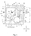
- a structure of the packing member 46 will be described with reference to Figures 1 , 8 , 9 and 10 .
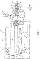
- Figure 1 is a schematic sectional view showing a packing state of the cartridge P in the packing member 46 in this embodiment.
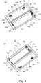
- Parts (a) and (b) of Figure 8 are schematic perspective views, as seen from different angles, each showing the packing member 46 in this embodiment.
- Parts (a) and (b) of Figure 9 are schematic perspective views, as seen from different angles, each showing a demountable state of the cartridge P from the packing member 46 in this embodiment.
- a longitudinal direction of the packing member 46 is the same as the longitudinal direction (X1 and X2 directions) of the cartridge P when the cartridge P is accommodated in the packing member 46.
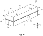
- Figure 10 is a schematic perspective view showing the cartridge-packed state of the packing member 46 in this embodiment.
- the packing member 46 is constituted by a frame portion 47, a cap portion 48 and a hinge portion 49.
- the frame portion 47 and the cap portion 48 are rotatable, relative to each other, after a rotation shaft 49a of the hinge portion 49 ( Figure 1 ).
- Each of the frame portion 47, the cap portion 48 are the hinge portion 49 which constitute the packing member 46 is constituted by a thin plate (sheet) of plastic (resin material), such as polyethylene terephthalate or polypropylene, and the resin material can be molded by vacuum molding, press molding, or injection molding. However, the resin material can be molded inexpensive by employing the vacuum molding.
- the frame portion 47 includes a first recessed portion 47c having a recessed shape provided with a first opening 47c1.
- the cap portion 48 includes a second recessed portion 48b having a recessed shape provided with a second opening 48b1.
- flange portions 47a and 48a are formed so as to surround the first recessed portion 47c and the second recessed portion 48b, respectively.
- the frame portion 47 and the cap portion 48 are connected at the hinge portion 49, thus being integrally molded.
- the cap portion 48 is capable of being located in a closed position where the cap portion 48 is capable of covering the first opening 47c1 of the frame portion 47 ( Figures 1 and 11 ) and an open position where the first opening 47c1 is open ( Figure 12 ).
- the mounting of the cartridge P in the packing member 46 will be described.
- the cartridge P is, as shown in (a) and (b) of Figure 9 , supported in a first state at the frame portion 47 of the packing member 46. This will be specifically described later.
- the cartridge P inserted into the packing member 46 in an arrow Z2 direction through the first opening 47c1 is detachably mounted in the packing member 46.
- the cartridge P is held by the frame portion 47 and the frame portion 47 covers the exposed portion 4b ((b) of Figure 4 ) of the photosensitive drum 4 of the cartridge P.
- the exposed portion 4b of the photosensitive drum 4 is prevented from contacting an inner surface of the frame portion 47 and a user is capable of gripping the grip portion 45 of the cartridge P.
- the cap portion 48 is rotated, about the rotation shaft 49a of the hinge portion 49, toward the frame portion 47, so that the flange portion 48a of the cap portion 48 is contacted to the flange portion 47a of the frame portion 47 as shown in Figure 10 . Thereafter, the flange portion 47a of the frame portion 47 and the flange portion 48a of the cap portion 48 are partly or wholly bonded to each other.
- the first recessed portion 47c of the frame portion 47 and the second recessed portion 48b of the cap portion 48 form a connecting portion 46a ( Figures 1 and 10 ) in combination.
- an accommodating space 46b is created inside the packing member 46, so that the packing member 46 is in a second state (packing state) in which the cartridge P is capable of being accommodated in the accommodating space 46b ( Figure 10 ).
- the second recessed portion 48b of the cap portion 48 covers the entire cartridge P or a part of the cartridge P so as to accommodate the grip portion 45 of the cartridge P which is the substantially rectangular parallelepiped.
- the connecting portion 46a includes an unpacking portion 46a1 at an opposing position from the hinge portion 49.
- the user unseals (unpacks) the packing member 46 from the unpacking portion 46a1 of the connecting portion 46a. Further, it is also possible to employ a constitution in which the frame portion 47 and the cap portion 48 are not bonded at the unpacking portion 46a1. By the above-described packing, the whole cartridge P is covered with the frame portion 47 and the cap portion 48 to be placed in the packed state ( Figures 1 and 10 ).
- the connecting portion 46a where the flange portion 47a of the frame portion 47 and the flange portion 48a of the cap portion 48 are connected with each other to accommodate the cartridge P is formed at a position which is roughly 1/2 of a height c of the cartridge P as seen from the longitudinal direction but is not limited thereto.
- the connecting portion may also be provided above the upper point of the height c of the cartridge P.
- the cartridge P is the substantially rectangular parallelepiped, and the packing member 46 includes the frame portion 47 and the cap portion 48 which are similar figures.
- the cartridge P may have any shape, and if the whole cartridge P or a part, of the cartridge P, to be protected, is covered with the packing member 46, also the packing member may have any shape.
- a bonding means between the flange portion 47a of the frame portion 47 and the flange portion 48a of the cap portion 48 it is possible to use (thermal) welding adhesive bonding, bonding with a double-side tape, hooking, or the like.
- the bonding means may only be required that the flange portions 47a and 48a can be bonded to each other, and is not limited to the above means. That is, it is also possible to employ a constitution in which the frame portion 47 and the cap portion 48 are separate members and the flange portions 47a and 48a are bonded to each other.
- the packing member 46 includes first limiting portions 47g and 47b formed at an upper surface of the frame portion 47 shown in (a) and (b) of Figure 8 .
- the cartridge P enters the frame portion 47.
- the Y1 and Y2 directions are a direction which crosses (is perpendicular to) the longitudinal direction of the cartridge P and which crosses (is perpendicular to) Z2 direction in which the cartridge P enters the frame portion 47.
- first limiting portions 47g and 47b are contacted to first portions-to-be-limited 24g, 25g, 24b and 24a shown in (a) and (b) of Figure 9 . Accordingly, the positions of the cartridge P with respect to the Y (Y1 and Y2) directions is limited in the first state described above. Further, as shown in (a) and (b) of Figure 8 , second limiting portions 48c are formed in the cap portion 48. Further, the second limiting portions 48c is, as shown in (a) and (b) of Figure 9 , formed at positions corresponding to second portions-to-be-limited 20c of the cartridge P in the packing state (second state) of the packing member 46.
- the packing state (second state) in the packing state (second state) the second portions-to-be-limited 26c contact the second limiting portions 48c of the cap portion 48.
- the cartridge P in the first state shown in (a) and (b) of Figure 9 , the cartridge P is not limited with respect to the Z1 direction opposite to the direction of gravitation.
- the packing member 46 does not contact the cartridge P at portions other than the limiting portions 47f, 47b, 48g and 47g shown in Figure 8 .
- the packing member 46 generates elastic deformation and plastic deformation at the portions other than the respective limiting portions when vibration and impact are generated during transportation, so that the packing member 46 is capable of absorbing the vibration and the impact during transportation. Therefore, the packing member 46 does not directly transmit the vibration and the impact during transportation to the photosensitive drum 4 and the process means and thus functions as a protecting member for protecting the cartridge P. Accordingly, it becomes also possible to eliminate a drum shutter, for protecting the photosensitive drum 4, from the cartridge P. Further, each of the limiting portions of the packing member 46 may be contacted to the cartridge P at any position if the position is not in a region where the electrostatic latent image is to be formed on the photosensitive drum 4 of the cartridge P.
- the cartridge P is less broken by the impact or the like during transportation.
- the cartridge P has already by positionally limited by the frame portion 47 of the packing member 46 with respect to the X1, X2, Y1, Y2 and Z1 directions. That is, in order to fix the cartridge P in the packing member 46, when the state of the packing member 46 is changed from the first state to the second state, the cartridge P is only required to be covered with the cap portion 48, so that an assembling property can be further improved.
- the limiting portions 47f, 47b, 48c and 47g are formed in the packing member 46 but may also be constituted as separate members.
- the developing device 9 is rotatably supported by the driving-side cover member 24 and the non-driving-side cover member 25 which are fixed on the cleaning unit 8 as described above. For that reason, as shown in (b) of Figure 11 , there is a possibility that the developing device 9 is rotationally moved in the clockwise direction (arrow W2 direction) against an urging force by the vibration and the impact generated during transportation of the cartridge P.
- the developing device 9 causes rotational motion by which the developing device 9 is restored to an attitude in which the developing device 9 is urged by the urging force, so that there is a possibility that the developing device 9 collides with the cleaning unit 8 and then friction memory between the photosensitive drum 4 and the developing roller 6 appears as an image defect.
- the developing device 9 includes the urging means such as the spring or the like has been described, but also in a constitution in which the developing device 9 does not include the urging means, during transportation of the cartridge P, there is a possibility that similar collision occurs.
- a fixing method in which the developing device 9 in the member 46 during transportation of the cartridge P is not readily moved relative to the cleaning unit 8 will be described.
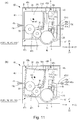
- Parts (a) and (b) of Figure 11 are schematic sectional views each showing the packing state in which the cartridge P is packed in the packing member 46.
- Part (a) of Figure 11 shows a state in which the developing device 9 is urged toward the cleaning frame (unit) 8 by a spring (not shown) or the like in the counterclockwise direction (arrow w1 direction) and in which the developing roller 6 contacts the photosensitive drum 4.
- (b) of Figure 11 shows a state in which the developing device 9 is rotationally moved relative to the cleaning frame 8 in the clockwise direction (arrow w2 direction) against the urging force.
- the developing device 9 includes a fourth portion-to-be-limited 29d.
- the cap portion 48 of the packing member 46 includes a fourth limiting portion 48d formed therein. That is as shown in (a) of Figure 11 , with respect to the counterclockwise direction (arrow w1 direction) with the rotation axis a ((a) of Figure 4 ) as the center, the fourth limiting portion 48d is provided upstream of the fourth portion-to-be-limited 29d.
- the fourth portion-to-be-limited 29d of the developing device 9 is supported by the fourth limiting portion 48d, so that excessive rotational movement of the developing device 9 in the clockwise direction (arrow w2 direction in (b) of Figure 11 ) can be suppressed.
- the fourth portion-to-be-limited 29d as a part of the developing device 9 and by forming the fourth limiting portion 48d as a part of the cap portion 48 of the packing member 46, it is possible to suppress the excessive rotational movement of the developing device 9 in the clockwise direction (arrow w2 direction in (b) of Figure 11 ).
- the cartridge P includes the grip portion 45 provided as a part of the cleaning unit 8, and is packed in an attitude in which the cleaning unit 8, the developing device 9 and the hinge portion 49 are arranged in this order in Y1 direction.
- the grip portion 45 is provided as a part of the developing device in some cases. In the case, the cartridge P is packed in an attitude in which the hinge portion 49, the cleaning unit 8 and the developing device 9 are arranged in Y1 direction.
- FIG. 12 is a schematic sectional view showing a state in which the cartridge P is demountable (detachable) from the packing member 46.
- the demounting operation of the cartridge P is performed in the order of uncovering of the cap portion 48, grip of the grip portion 45, demounting of the cartridge P and mounting of the cartridge P into the apparatus main assembly 2.
- the user separates the connecting portion 46a of the cap portion 48, connected openably with the frame portion 47, from an unpacking portion 46a1 by an unshown means. That is, from the connecting portion 46a where the flange portion 47a is located, the flange portion 48a is separated. Then, the user rotationally moves the cap portion 48 about a rotation shaft 49a of the hinge portion 49 as an axis in an arrow R direction in Figure 12 . By about 180-degree rotational movement of the cap portion 48, the cartridge P is in a demountable state ( Figure 12 ), so that the uncovering operation of the cap portion 48 is completed. Incidentally, if the cartridge P is demountable, the cap portion 48 may also be not rotated by 180 degrees.
- the user easily performs the uncovering operation of the packing member 46 in the case where the unpacking portion 46a1 is disposed in the front side rather than in the case where the hinge portion 49 is disposed in the front side.
- the uncovering by the user is performed in the state in which the unpacking portion 46a1 of the packing member 46 is disposed in the front side.
- the user grips the grip portion 45.
- the grip of the grip portion 45 by the user is made by gripping the grip portion 45 after the user rotationally moves the cap portion 48.
- the grip portion 45 is located in the unpacking portion 46a1 side. For that reason, the user easily recognizes the grip portion 45 when the cap portion 48 is uncovered and can smoothly perform the grip of the grip portion 45 with no obstruction to a gripping operation by the cap portion 48.
- the photosensitive drum 4 is located in the downstream side and the grip portion 45 is located in the upstream side.
- This attitude is the same as that of the cartridge P when the user grips the grip portion 45 of the cartridge P accommodated in the packing member 46. That is, the user can mount the cartridge P into the apparatus main assembly in the attitude, in which the user demount the cartridge P from the packing member 46, as it is. Therefore, the user is free from inconveniences, such that the cartridge P is shifted from one hand to the other and such that the wrist is twisted, during the mounting of the cartridge P, after being demounted, into the apparatus main assembly 2, thus leading to improvement in usability.
- the packing member 46 when the vibration and the impact during transportation are generated, the packing member 46 permits generation of elastic deformation and plastic deformation at portions other than the respective limiting portions and thus is capable of absorbing the vibration and the impact during transportation.
- the packing member 46 functions as a cartridge packing member capable of protecting the cartridge P from the vibration and the impact during transportation.
- the cartridge P is constituted by the first frame 8 as the cleaning frame for rotatably supporting the photosensitive drum 4 and by the second frame 9 as the developing frame, supported by the first frame 8, for supporting the process means.
- the packing member 46 includes the fourth limiting portion 48d for limiting movement of the second frame 9 in the accommodating space 46b.
- the cartridge P has the grip portion 45, to be gripped for demounting the cartridge P from the packing member, at a develop opposite from the photosensitive drum 4.
- the photosensitive drum 4 is disposed in the frame portion 47 side and the grip portion 45 is disposed in the cap portion 48 side.
- the constitution in which the cartridge P is formed in the substantially rectangular parallelepiped shape and the grip portion 45 is disposed at a surface opposite from the exposed portion of the photosensitive drum 4 is employed, but the present invention is not limited thereto.
- the cartridge P is packed in the packing member 46, it is also possible to apply the present invention when a constitution such that the exposed portion 4b is accommodated in the first recessed portion 47c of the frame portion 47 and the grip portion 45 is accommodated in the second recessed portion 48b of the cap portion 48 is employed.
- the cartridge is formed in a substantially triangular prism shape and an exposed portion is provided in a side other than triangular sides.
- the grip portion is disposed in a side which is not opposite from the exposed portion side.
- the present invention is applicable when the cartridge is packed in the packing member, a constitution in which the exposed portion is accommodated in a recessed portion of the frame portion and the grip portion is accommodated in a recessed portion of the cap portion may only be required to be employed.
- this embodiment relates to the packing member 46 for packing the cartridge P and relates to the cartridge P packed in the packing member 46.
- the cartridge P is constituted by the cleaning unit 8 as the first frame including the grip portion 45 and the developing device 9 as the second frame.
- the packing member 46 is constituted by the frame portion 47 and the cap portion 48 which are connected by the hinge portion 49 as a rotation shaft for rotatably supporting the frame portion 47 and the cap portion 48 relative to each other.
- the frame portion 47 includes the first recessed portion 47c
- the cap portion 48 includes the second recessed portion 48b.
- each of these portions 47 and 48 of the packing member 46 is rotatable about the hinge portion 49 as a rotation center, and the first recessed portion 47c and the second recessed portion 48b form the accommodating space 46b which is a space for accommodating the cartridge P.
- the cartridge P is positionally limited by the limiting portions 47g and 47b in the following manner when the cartridge P is packed in the accommodating space 46b of the packing member 46. That is, with respect to the direction perpendicular to the axial directions X1 and X2 of the photosensitive drum 4 and with respect to the direction crossing the entering direction in which the cartridge P enters the frame portion 47, a state in which the hinge portion 49, the developing device 9 and the cleaning unit 8 are arranged in this order is created.
- the user is easy to recognize the grip portion 45 since when the user unpacks the packing member 46 in the front side where the unpacking portion 46a1 is located, the grip portion 45 of the cleaning unit 8 is closer in position to the user. Further, the cap portion 48 does not obstruct the gripping operation, and therefore the user is easy to grip the grip portion 45. For that reason, the user can smoothly demount the cartridge P from the packing member 46. Further, an attitude of the cartridge P when the user demounts the cartridge P from the packing member 46 and an attitude of the cartridge P when the user mounts the cartridge P into the apparatus main assembly 2 are substantially coincide with each other.
- the user can reduce an operation, to the possible extent, in which the user shifts the cartridge P from one hand to the other or twists the user is wrist. For that reason, according to this embodiment, usability is remarkably improved.
- Embodiment 2 will be described with reference to Figures 13 to 15 .
- cartridges Q Q (QY, QM, QC, QK) each constituted by only the developing device are used. For that reason, with respect to portions common to Embodiments 1 and 2, description of the portions will be omitted.
- Figure 14 is a schematic sectional view of an image forming apparatus 100 in this embodiment.
- the image forming apparatus 1 is a four color-based full-color laser printer using the electrophotographic image forming process and effects color image formation on a recording material S.
- the cartridge Q is, as shown in Figure 14 , detachably mountable to an apparatus main assembly 102 and a color image is formed on the recording material S.
- Parts (a) and (b) of Figure 13 are schematic perspective views each showing the cartridge Q in this embodiment, in which (a) is the schematic perspective view of the cartridge Q as seen from the driving side, and (b) is the schematic perspective view of the cartridge Q as seen from the non-driving side.
- the cartridge Q includes a grip portion 145.
- the grip portion 145 is a portion to be gripped by the user, and is mounted on a developing (device) frame 129 integrally or as a separate member.
- the cartridge Q is the substantially rectangular parallelepiped.
- a side 158 includes an exposed portion 6b for permitting development of the electrostatic latent image on the photosensitive drum 4 with the toner on the developing roller 6.
- a side 159 opposite from the side 158 includes the above-described grip portion 145. The position of the grip portion 145 will be described later.
- the cartridge Q includes, as portion to be positionally limited in a packing member 146 when the cartridge Q is packed in the packing member 146 described later, third portions-to-be-limited 139f and 144f, first portions-to-be-limited 129b, 144b, 139g and 144g, and a second portion-to-be-limited 129c.
- the third portions-to-be-limited 139f and 144f are used for positional limitation of the cartridge Q in the packing member 146 described later with respect to the longitudinal direction (X (X1, X2) direction in Figure 10 ) which is the axial direction of the developing roller 6.
- the first portions-to-be-limited 139b and 144b and the second portion-to-be-limited 129c are used for positional limitation of the cartridge Q with respect to Y1 and Y2 directions perpendicular to (crossing) the X1 and X2 directions and with respect to Z1 direction as the vertically downward direction, respectively.
- the positional limitation of the cartridge Q in the packing member 146 by using the respective portions-to-be-limited will be specifically described later.
- Figure 14 is a schematic sectional view showing a state in which a cartridge tray 43 is pulled out from the apparatus main assembly 102 and thus the cartridge Q is detachably mountable to the cartridge tray 43, and is a schematic sectional view for illustrating an operation by which the cartridge Q is demounted from and mounted into the cartridge tray 43.
- the cartridge tray 43 in which the cartridges Q are mountable is provided inside the apparatus main assembly 102. Further, in the cartridge tray 43, the cleaning unit 8 is mounted in advance.
- the cartridge tray 43 is, as shown in Figure 14 , constituted so as to be linearly movable (pullable and pushable) in G1 and G2 directions which are substantially the horizontal direction with respect to the apparatus main assembly 102. Further, the cartridge tray 43 is capable of being in a mounted position in the apparatus main assembly 102 and in a pulled-out position where the cartridge tray 43 is pulled out from the mounted position.
- the openable door 3 is opened, and then the cartridge tray 43 is moved in G1 direction indicated by an arrow in Figure 14 to be moved to the pulled-out position.
- the cartridge Q is mounted in the cartridge tray 43 from an arrow H1 direction in Figure 14 , so that an exposed portion 6b ( Figure 13 ) of the developing roller 6 is positioned at an opposing portion to the photosensitive drum 4.
- the cartridge tray 43 is moved in an arrow G2 direction shown in Figure 14 , so that the cartridge tray 43 is moved to the mounted position in the apparatus main assembly 102.
- the openable door 3 is closed, so that the mounting operation of the cartridge Q into the apparatus main assembly 102 is completed.
- the demounting operation of the cartridge Q from the apparatus main assembly 102 will be described.
- the cartridge tray 43 is moved in the arrow G1 direction in Figure 14 to the pulled-out position.
- the cartridge Q is demounted in an arrow H2 direction shown in Figure 14 , so that the demounting operation of the cartridge Q from the apparatus main assembly 102 is completed.
- the cartridge Q is detachably mountable to the apparatus main assembly 102,
- the cleaning 8 is mounted in the cartridge tray 43 in advance, but the constitution is not limited thereto. It is also possible to employ a constitution in which the cleaning unit 8 is disposed in the apparatus main assembly 102 in advance. A process from demounting of the cartridge Q from the packing member 143 until the cartridge Q is mounted into the apparatus main assembly 102 will be described specifically.
- Figure 15 is a schematic sectional view showing a packing state of the cartridge Q in the packing member 46 in this embodiment.
- the packing member 146 is constituted by a frame portion 147, a cap portion 148 and a hinge portion 149.
- the frame portion 147 and the cap portion 148 are rotatable, relative to each other, after a rotation shaft 149a of the hinge portion 149.
- Each of the frame portion 147, the cap portion 148 are the hinge portion 149 which constitute the packing member 146 is constituted by a thin film of plastic (resin material), such as polyethylene terephthalate or polypropylene and the resin material can be molded by vacuum molding, press molding, or injection molding.
- the packing member 146 is processable at low cost by being formed by the vacuum molding.
- the packing member 146 includes a connecting portion 146a for unpacking the packing member 146.
- the connecting portion 146a is located in a position where it is opposite from the hinge portion 149 in the packing state of the packing member 146.
- the frame portion 147 includes a first recessed portion 147c having a recessed shape provided with a first opening 147c1. Further, the cap portion 148 includes a second recessed portion 148b having a recessed shape provided with a second opening 148b1. Further, at the frame portion 147 and the cap portion 148, flange portions 147a and 148a are formed so as to surround the first recessed portion 147c and the second recessed portion 148b, respectively. The frame portion 147 and the cap portion 148 are connected at the hinge portion 149, thus being integrally molded. Further, the cap portion 148 is capable of being located in a closed position where the cap portion 148 is capable of covering the first opening 147c1 of the frame portion 147 ( Figures 1 and 11 ) and an open position where the first opening 147c1 is open.
- the cartridge Q is supported in a first state at the frame portion 147 of the packing member 146. This will be specifically described later.
- the cartridge Q inserted into the packing member 146 through the first opening 147c1 is detachably mounted in the packing member 146.
- the cartridge Q is held by the frame portion 147 and the frame portion 147 covers the exposed portion 6b of the developing roller 6 of the cartridge Q.
- the exposed portion 6b of the developing roller 6 is prevented from contacting an inner surface of the frame portion 147 and the cap portion 148 is rotated, relative to the frame portion 147, about a rotation shaft 149a of the hinge portion 149, and a user is capable of gripping the grip portion 145 of the cartridge Q.
- the cap portion 148 is rotated, about the rotation shaft 149a of the hinge portion 149, toward the frame portion 147, so that the flange portion 148a of the cap portion 148 is contacted to the flange portion 147a of the frame portion 147 as shown in Figure 15 .
- the flange portion 47a of the frame portion 47 and the flange portion 48a of the cap portion 48 which oppose each other are partly or wholly bonded to each other.
- the first recessed portion 147c of the frame portion 147 and the second recessed portion 148b of the cap portion 148 form a connecting portion 146a in combination, thus creating an accommodating space 146b inside the packing member 146, so that the packing member 146 is capable of being accommodated in the accommodating space 146b.
- the second recessed portion 148b of the cap portion 148 covers the entire cartridge Q or a part of the cartridge Q so as to accommodate the grip portion 145 of the cartridge Q which is the substantially rectangular parallelepiped.
- the first limiting portions 147g and 147b formed at the inner surface of the frame portion 148 of the packing member 146 are contacted to first portions-to-be-limited 144g and 144b shown in (a) and (b) of Figure 13 . Accordingly, the positions of the cartridge Q with respect to the Y1, Y2, and Z directions is limited in the first state described above. Further, as shown in Figure 15 , the second limiting portion 148c is formed in the cap portion 148. Further, the second limiting portion 148c is formed at a position corresponding to second portion-to-be-limited 129c of the cartridge Q in the packing state (second state) of the packing member 146.
- the packing state (second state) in the packing state (second state) the second portion-to-be-limited 129c contacts the second limiting portion 148c of the cap portion 148.
- the positional limitation of the cartridge Q in Z1 direction is made. That is, in the first state, the cartridge Q is not limited with respect to the Z1 direction opposite to the direction of gravitation.
- the packing member 146 does not contact the cartridge Q at portions other than the limiting portion 144f, 147b, 148g and 147g shown in Figure 15 .
- the packing member 146 similarly as in Embodiment 1, the packing member 146 generates elastic deformation and plastic deformation at the portions other than the respective limiting portions when vibration and impact are generated during transportation, so that the packing member 146 is capable of absorbing the vibration and the impact during transportation. Therefore, the packing member 146 does not directly transmit the vibration and the impact during transportation to the developing roller 6 and other process means and thus functions as a protecting member for protecting the cartridge Q. Further, each of the limiting portions of the packing member 146 may be contacted to the cartridge Q at any position if the position is not in a region where the development is to be made by using the developing roller 6 of the cartridge Q.
- the cartridge Q is less broken by the impact or the like during transportation.
- the cartridge Q has already by positionally limited by the frame portion 147 of the packing member 146 with respect to the longitudinal direction Y1, Y2 and Z1 directions. That is, in order to fix the cartridge Q in the packing member 146, when the state of the packing member 146 is changed from the first state to the second state, the cartridge Q is only required to be covered with the cap portion 148, so that an assembling property can be further improved.
- the third limiting portions 144f, 147b, 148c and 147g are formed in the frame portion 147 and cap portion 148 of the packing member 146 but may also be constituted as separate members.
- FIG. 15 A positional relationship between the grip portion 145 of the cartridge Q and the packing member 146 will be described with reference to Figure 15 .
- the closest edge line, to the hinge portion 149, of the cartridge Q is a first edge line 109a
- the remotest edge line, from the hinge portion 149, of the cartridge Q is a second edge line 109b.
- a medium line between the first and second edge lines 109a and 109b is a center line m.
- the grip portion 145 is provided in the right side of the center line m in Figure 15 (with respect to Y2 direction).
- the cartridge Q when the cartridge Q is packed in the packing member 146, the cartridge Q is in an attitude such that the grip portion 145 is disposed in a side opposite from the hinge portion 149 side with respect to the center line m. Further, the demounting operation of the cartridge Q from the packing member 146 is the same as that in Embodiment 1 in which the cartridge P is replaced with the cartridge Q in this embodiment, and therefore will be omitted from description.
- this embodiment relates to the packing member 146 for packing the cartridge Q and relates to the cartridge Q packed in the packing member 146.
- the cartridge Q includes the grip portion 145 and at least one of the photosensitive drum as the image bearing member and the process means actable on the photosensitive drum.
- the packing member 146 is constituted by the frame portion 147 and the cap portion 148 which are connected by the hinge portion 149 as a rotation shaft for rotatably supporting the frame portion 147 and the cap portion 148 relative to each other.
- the frame portion 147 includes the first recessed portion 147c
- the cap portion 148 includes the second recessed portion 148b.
- each of these portions 147 and 148 of the packing member 46 is rotatable about the rotation shaft 149 as a rotation center, and the first recessed portion 147c and the second recessed portion 148b form the accommodating space 146b which is a space for accommodating the cartridge Q.
- the cartridge Q is positionally limited by the limiting portions 147g and 147b in the following manner when the cartridge Q is packed in the accommodating space 46b. That is, with respect to the direction perpendicular to the axial directions X1 and X2 of the developing roller 6 and with respect to the direction crossing the entering direction in which the cartridge Q enters the frame portion 147, a state in which the hinge portion 149 is located in a position remoter from the hinge portion 149 than the center line m is created.
- the user is easy to recognize the grip portion 145 since when the user unpacks the packing member 146 in the front side where the unpacking portion 146a1 is located, the grip portion 145 is closer in position to the user. Further, the cap portion 148 does not obstruct the gripping operation, and therefore the user is easy to grip the grip portion 145. For that reason, the user can smoothly demount the cartridge Q from the packing member 146. Further, an attitude of the cartridge Q when the user demounts the cartridge Q from the packing member 146 and an attitude of the cartridge Q when the user mounts the cartridge Q into the apparatus main assembly 102 are substantially coincide with each other.
- the user can reduce an operation, to the possible extent, in which the user shifts the cartridge Q from one hand to the other or twists the user is wrist. For that reason, according to this embodiment, usability is remarkably improved.
Landscapes
- Engineering & Computer Science (AREA)
- Mechanical Engineering (AREA)
- Physics & Mathematics (AREA)
- General Physics & Mathematics (AREA)
- Life Sciences & Earth Sciences (AREA)
- Manufacturing & Machinery (AREA)
- Sustainable Development (AREA)
- Computer Vision & Pattern Recognition (AREA)
- Electrophotography Configuration And Component (AREA)
Applications Claiming Priority (2)
| Application Number | Priority Date | Filing Date | Title |
|---|---|---|---|
| JP2012131295A JP6112783B2 (ja) | 2012-06-08 | 2012-06-08 | 梱包体 |
| PCT/JP2013/066409 WO2013183793A1 (en) | 2012-06-08 | 2013-06-07 | Packing member and cartridge packed in the packing member |
Publications (2)
| Publication Number | Publication Date |
|---|---|
| EP2858916A1 EP2858916A1 (en) | 2015-04-15 |
| EP2858916B1 true EP2858916B1 (en) | 2020-04-08 |
Family
ID=48771675
Family Applications (1)
| Application Number | Title | Priority Date | Filing Date |
|---|---|---|---|
| EP13735082.3A Active EP2858916B1 (en) | 2012-06-08 | 2013-06-07 | Packing member and cartridge packed in the packing member |
Country Status (7)
Families Citing this family (13)
| Publication number | Priority date | Publication date | Assignee | Title |
|---|---|---|---|---|
| TWI574892B (zh) | 2012-06-08 | 2017-03-21 | 佳能股份有限公司 | 包裝構件及包裝在該包裝構件之匣 |
| JP6108728B2 (ja) * | 2012-08-31 | 2017-04-05 | キヤノン株式会社 | 梱包材及びカートリッジ |
| JP6415198B2 (ja) | 2013-09-12 | 2018-10-31 | キヤノン株式会社 | カートリッジ |
| JP6392323B2 (ja) | 2014-03-25 | 2018-09-19 | 三洋電機株式会社 | バッテリシステム |
| JP6855284B2 (ja) | 2017-03-03 | 2021-04-07 | キヤノン株式会社 | カートリッジ及び画像形成装置 |
| MX2019015104A (es) | 2017-06-15 | 2020-02-05 | Canon Kk | Cartucho y aparato para la formacion de imagenes electrofotograficas. |
| WO2019176890A1 (en) * | 2018-03-15 | 2019-09-19 | Canon Kabushiki Kaisha | Packing member and packing unit |
| JP7306017B2 (ja) * | 2019-03-28 | 2023-07-11 | ブラザー工業株式会社 | 包装装置及びその内側箱体 |
| KR20250100797A (ko) | 2019-06-12 | 2025-07-03 | 캐논 가부시끼가이샤 | 카트리지, 어태치먼트, 및 장착 키트 |
| WO2021250983A1 (ja) | 2020-06-08 | 2021-12-16 | キヤノン株式会社 | トナー容器及び画像形成システム |
| EP4152105B1 (en) | 2020-12-07 | 2024-06-05 | Canon Kabushiki Kaisha | Toner container and image forming system |
| EP4310597A4 (en) | 2021-03-16 | 2025-02-19 | Canon Kabushiki Kaisha | Toner cartridge and image-forming device |
| JP7693478B2 (ja) | 2021-09-16 | 2025-06-17 | キヤノン株式会社 | カートリッジ保護組立体 |
Family Cites Families (38)
| Publication number | Priority date | Publication date | Assignee | Title |
|---|---|---|---|---|
| US2217455A (en) * | 1937-11-20 | 1940-10-08 | Western Electric Co | Package |
| JPS6144683A (ja) | 1984-08-10 | 1986-03-04 | Honshu Paper Co Ltd | 感熱記録体 |
| JPH02304460A (ja) * | 1989-05-19 | 1990-12-18 | Nec Corp | プロセスユニットの梱包箱 |
| JPH04114173A (ja) | 1990-09-04 | 1992-04-15 | Canon Inc | プロセスカートリッジの梱包材 |
| JPH05232752A (ja) * | 1992-02-20 | 1993-09-10 | Ricoh Co Ltd | 画像形成装置のプロセスカートリッジ |
| US5335770A (en) * | 1992-08-06 | 1994-08-09 | Moulded Fibre Technology, Inc. | Molded pulp fiber interior package cushioning structures |
| DE69320738T2 (de) | 1992-09-04 | 1999-02-18 | Canon K.K., Tokio/Tokyo | Arbeitseinheit und Bilderzeugungsgerät |
| US6408142B1 (en) | 1992-09-04 | 2002-06-18 | Canon Kabushiki Kaisha | Process cartridge and image forming apparatus |
| JPH06186895A (ja) * | 1992-12-16 | 1994-07-08 | Ricoh Co Ltd | 梱包箱 |
| JP3530644B2 (ja) | 1995-07-31 | 2004-05-24 | キヤノン株式会社 | 現像フレーム及びプロセスカートリッジ及び電子写真画像形成装置 |
| JPH1029616A (ja) * | 1996-07-15 | 1998-02-03 | Saidetsuku Kk | 物品の搬送用容器 |
| USD395234S (en) * | 1996-07-25 | 1998-06-16 | Sydek Kabushiki Kaisha | Safeguard case for toner cartridge |
| JPH11242371A (ja) | 1997-10-31 | 1999-09-07 | Canon Inc | コネクタ及びユニット及びプロセスカ―トリッジ及び電子写真画像形成装置 |
| US6321911B1 (en) * | 2000-01-31 | 2001-11-27 | Display Pack, Inc. | Fragility package |
| US6920980B2 (en) * | 2002-06-24 | 2005-07-26 | Hewlett-Packard Development Company, L.P. | Container |
| US7243815B2 (en) * | 2002-09-23 | 2007-07-17 | See The Shoes, Llc | Thermoformed package |
| JP3639834B2 (ja) | 2003-05-19 | 2005-04-20 | キヤノン株式会社 | 梱包部材、及び、梱包部材を用いた梱包方法、及び、梱包部材の製造方法 |
| JP3885062B2 (ja) | 2004-03-30 | 2007-02-21 | キヤノン株式会社 | 電子写真感光体ドラム、プロセスカートリッジおよび電子写真画像形成装置 |
| JP4630615B2 (ja) | 2004-03-30 | 2011-02-09 | キヤノン株式会社 | プロセスカートリッジ、プロセスカートリッジの組立て方法 |
| JP4110128B2 (ja) | 2004-04-26 | 2008-07-02 | キヤノン株式会社 | プロセスカートリッジ、電子写真画像形成装置及び軸受部材 |
| US7158749B2 (en) | 2004-04-26 | 2007-01-02 | Canon Kabushiki Kaisha | Cleaning device, process cartridge, cleaning member and electrophotographic image forming apparatus |
| JP3840232B2 (ja) | 2004-05-06 | 2006-11-01 | キヤノン株式会社 | プロセスカートリッジ |
| US20060042995A1 (en) * | 2004-09-02 | 2006-03-02 | Ade, Inc. | Suspension packages |
| JP4856974B2 (ja) | 2005-02-22 | 2012-01-18 | キヤノン株式会社 | 帯電装置、プロセスカートリッジ及び画像形成装置 |
| JP4280772B2 (ja) | 2006-12-28 | 2009-06-17 | キヤノン株式会社 | プロセスカートリッジ及び電子写真画像形成装置 |
| US7856192B2 (en) | 2006-12-28 | 2010-12-21 | Canon Kabushiki Kaisha | Process cartridge and electrophotographic image forming apparatus |
| JP5094186B2 (ja) | 2007-04-10 | 2012-12-12 | キヤノン株式会社 | プロセスカートリッジ及び電子写真画像形成装置 |
| JP5288900B2 (ja) * | 2008-06-20 | 2013-09-11 | キヤノン株式会社 | プロセスカートリッジ及び電子写真画像形成装置 |
| JP2010102006A (ja) | 2008-10-22 | 2010-05-06 | Canon Inc | 画像形成装置 |
| US8328034B2 (en) * | 2009-06-08 | 2012-12-11 | 3Rd Stone Design Inc. | Food container |
| US8942592B2 (en) | 2009-12-16 | 2015-01-27 | Canon Kabushiki Kaisha | Process cartridge, photosensitive drum unit, developing unit and electrophotographic image forming apparatus |
| JP5690655B2 (ja) | 2011-05-26 | 2015-03-25 | 株式会社沖データ | 画像形成ユニット |
| JP6021620B2 (ja) | 2011-12-06 | 2016-11-09 | キヤノン株式会社 | 電子写真画像形成装置本体に着脱可能なカートリッジ |
| TWI574892B (zh) * | 2012-06-08 | 2017-03-21 | 佳能股份有限公司 | 包裝構件及包裝在該包裝構件之匣 |
| JP6108728B2 (ja) * | 2012-08-31 | 2017-04-05 | キヤノン株式会社 | 梱包材及びカートリッジ |
| JP6218493B2 (ja) | 2012-09-06 | 2017-10-25 | キヤノン株式会社 | ユニット、ユニットの製造方法、及び画像形成装置、画像形成装置の製造方法 |
| US9002235B2 (en) * | 2013-02-27 | 2015-04-07 | Hewlett-Packard Development Company, L.P. | Toner cartridge packaging |
| JP2014237472A (ja) * | 2013-06-07 | 2014-12-18 | キヤノン株式会社 | 梱包部材、梱包部材に梱包されたカートリッジ |
-
2012
- 2012-06-08 JP JP2012131295A patent/JP6112783B2/ja active Active
-
2013
- 2013-06-07 CN CN201380029207.5A patent/CN104334469B/zh active Active
- 2013-06-07 KR KR1020147033865A patent/KR20150006046A/ko not_active Ceased
- 2013-06-07 TW TW104123869A patent/TWI598276B/zh active
- 2013-06-07 US US14/396,537 patent/US9423767B2/en active Active
- 2013-06-07 TW TW102120331A patent/TWI505976B/zh active
- 2013-06-07 EP EP13735082.3A patent/EP2858916B1/en active Active
- 2013-06-07 WO PCT/JP2013/066409 patent/WO2013183793A1/en active Application Filing
Non-Patent Citations (1)
| Title |
|---|
| None * |
Also Published As
| Publication number | Publication date |
|---|---|
| WO2013183793A1 (en) | 2013-12-12 |
| EP2858916A1 (en) | 2015-04-15 |
| US20150114870A1 (en) | 2015-04-30 |
| TW201540618A (zh) | 2015-11-01 |
| TW201406622A (zh) | 2014-02-16 |
| KR20150006046A (ko) | 2015-01-15 |
| US9423767B2 (en) | 2016-08-23 |
| JP2013254175A (ja) | 2013-12-19 |
| CN104334469B (zh) | 2017-02-22 |
| CN104334469A (zh) | 2015-02-04 |
| JP6112783B2 (ja) | 2017-04-12 |
| TWI598276B (zh) | 2017-09-11 |
| TWI505976B (zh) | 2015-11-01 |
Similar Documents
| Publication | Publication Date | Title |
|---|---|---|
| EP2858916B1 (en) | Packing member and cartridge packed in the packing member | |
| EP2713224B1 (en) | Packaged cartridge, packing material and cartridge | |
| US10427867B2 (en) | Packing member and cartridge packed in the packing member | |
| US9727021B2 (en) | Cartridge, image forming apparatus and manufacturing method of the cartridge | |
| US9720374B2 (en) | Cartridge, image forming apparatus and manufacturing method of the cartridge | |
| JP2014237472A (ja) | 梱包部材、梱包部材に梱包されたカートリッジ | |
| JP6297187B2 (ja) | 梱包材及びカートリッジ | |
| JP2014081404A (ja) | 梱包部材、梱包部材に梱包されたカートリッジ |
Legal Events
| Date | Code | Title | Description |
|---|---|---|---|
| PUAI | Public reference made under article 153(3) epc to a published international application that has entered the european phase |
Free format text: ORIGINAL CODE: 0009012 |
|
| 17P | Request for examination filed |
Effective date: 20150108 |
|
| AK | Designated contracting states |
Kind code of ref document: A1 Designated state(s): AL AT BE BG CH CY CZ DE DK EE ES FI FR GB GR HR HU IE IS IT LI LT LU LV MC MK MT NL NO PL PT RO RS SE SI SK SM TR |
|
| AX | Request for extension of the european patent |
Extension state: BA ME |
|
| DAX | Request for extension of the european patent (deleted) | ||
| 17Q | First examination report despatched |
Effective date: 20160201 |
|
| STAA | Information on the status of an ep patent application or granted ep patent |
Free format text: STATUS: EXAMINATION IS IN PROGRESS |
|
| GRAP | Despatch of communication of intention to grant a patent |
Free format text: ORIGINAL CODE: EPIDOSNIGR1 |
|
| STAA | Information on the status of an ep patent application or granted ep patent |
Free format text: STATUS: GRANT OF PATENT IS INTENDED |
|
| INTG | Intention to grant announced |
Effective date: 20191024 |
|
| GRAS | Grant fee paid |
Free format text: ORIGINAL CODE: EPIDOSNIGR3 |
|
| GRAA | (expected) grant |
Free format text: ORIGINAL CODE: 0009210 |
|
| STAA | Information on the status of an ep patent application or granted ep patent |
Free format text: STATUS: THE PATENT HAS BEEN GRANTED |
|
| AK | Designated contracting states |
Kind code of ref document: B1 Designated state(s): AL AT BE BG CH CY CZ DE DK EE ES FI FR GB GR HR HU IE IS IT LI LT LU LV MC MK MT NL NO PL PT RO RS SE SI SK SM TR |
|
| REG | Reference to a national code |
Ref country code: AT Ref legal event code: REF Ref document number: 1254097 Country of ref document: AT Kind code of ref document: T Effective date: 20200415 Ref country code: CH Ref legal event code: EP |
|
| REG | Reference to a national code |
Ref country code: IE Ref legal event code: FG4D |
|
| REG | Reference to a national code |
Ref country code: DE Ref legal event code: R096 Ref document number: 602013067675 Country of ref document: DE |
|
| REG | Reference to a national code |
Ref country code: NL Ref legal event code: MP Effective date: 20200408 |
|
| REG | Reference to a national code |
Ref country code: LT Ref legal event code: MG4D |
|
| PG25 | Lapsed in a contracting state [announced via postgrant information from national office to epo] |
Ref country code: FI Free format text: LAPSE BECAUSE OF FAILURE TO SUBMIT A TRANSLATION OF THE DESCRIPTION OR TO PAY THE FEE WITHIN THE PRESCRIBED TIME-LIMIT Effective date: 20200408 Ref country code: SE Free format text: LAPSE BECAUSE OF FAILURE TO SUBMIT A TRANSLATION OF THE DESCRIPTION OR TO PAY THE FEE WITHIN THE PRESCRIBED TIME-LIMIT Effective date: 20200408 Ref country code: LT Free format text: LAPSE BECAUSE OF FAILURE TO SUBMIT A TRANSLATION OF THE DESCRIPTION OR TO PAY THE FEE WITHIN THE PRESCRIBED TIME-LIMIT Effective date: 20200408 Ref country code: NL Free format text: LAPSE BECAUSE OF FAILURE TO SUBMIT A TRANSLATION OF THE DESCRIPTION OR TO PAY THE FEE WITHIN THE PRESCRIBED TIME-LIMIT Effective date: 20200408 Ref country code: PT Free format text: LAPSE BECAUSE OF FAILURE TO SUBMIT A TRANSLATION OF THE DESCRIPTION OR TO PAY THE FEE WITHIN THE PRESCRIBED TIME-LIMIT Effective date: 20200817 Ref country code: NO Free format text: LAPSE BECAUSE OF FAILURE TO SUBMIT A TRANSLATION OF THE DESCRIPTION OR TO PAY THE FEE WITHIN THE PRESCRIBED TIME-LIMIT Effective date: 20200708 Ref country code: GR Free format text: LAPSE BECAUSE OF FAILURE TO SUBMIT A TRANSLATION OF THE DESCRIPTION OR TO PAY THE FEE WITHIN THE PRESCRIBED TIME-LIMIT Effective date: 20200709 Ref country code: IS Free format text: LAPSE BECAUSE OF FAILURE TO SUBMIT A TRANSLATION OF THE DESCRIPTION OR TO PAY THE FEE WITHIN THE PRESCRIBED TIME-LIMIT Effective date: 20200808 |
|
| REG | Reference to a national code |
Ref country code: AT Ref legal event code: MK05 Ref document number: 1254097 Country of ref document: AT Kind code of ref document: T Effective date: 20200408 |
|
| PG25 | Lapsed in a contracting state [announced via postgrant information from national office to epo] |
Ref country code: BG Free format text: LAPSE BECAUSE OF FAILURE TO SUBMIT A TRANSLATION OF THE DESCRIPTION OR TO PAY THE FEE WITHIN THE PRESCRIBED TIME-LIMIT Effective date: 20200708 Ref country code: RS Free format text: LAPSE BECAUSE OF FAILURE TO SUBMIT A TRANSLATION OF THE DESCRIPTION OR TO PAY THE FEE WITHIN THE PRESCRIBED TIME-LIMIT Effective date: 20200408 Ref country code: LV Free format text: LAPSE BECAUSE OF FAILURE TO SUBMIT A TRANSLATION OF THE DESCRIPTION OR TO PAY THE FEE WITHIN THE PRESCRIBED TIME-LIMIT Effective date: 20200408 Ref country code: HR Free format text: LAPSE BECAUSE OF FAILURE TO SUBMIT A TRANSLATION OF THE DESCRIPTION OR TO PAY THE FEE WITHIN THE PRESCRIBED TIME-LIMIT Effective date: 20200408 |
|
| PG25 | Lapsed in a contracting state [announced via postgrant information from national office to epo] |
Ref country code: AL Free format text: LAPSE BECAUSE OF FAILURE TO SUBMIT A TRANSLATION OF THE DESCRIPTION OR TO PAY THE FEE WITHIN THE PRESCRIBED TIME-LIMIT Effective date: 20200408 |
|
| REG | Reference to a national code |
Ref country code: DE Ref legal event code: R097 Ref document number: 602013067675 Country of ref document: DE |
|
| PG25 | Lapsed in a contracting state [announced via postgrant information from national office to epo] |
Ref country code: SM Free format text: LAPSE BECAUSE OF FAILURE TO SUBMIT A TRANSLATION OF THE DESCRIPTION OR TO PAY THE FEE WITHIN THE PRESCRIBED TIME-LIMIT Effective date: 20200408 Ref country code: IT Free format text: LAPSE BECAUSE OF FAILURE TO SUBMIT A TRANSLATION OF THE DESCRIPTION OR TO PAY THE FEE WITHIN THE PRESCRIBED TIME-LIMIT Effective date: 20200408 Ref country code: AT Free format text: LAPSE BECAUSE OF FAILURE TO SUBMIT A TRANSLATION OF THE DESCRIPTION OR TO PAY THE FEE WITHIN THE PRESCRIBED TIME-LIMIT Effective date: 20200408 Ref country code: EE Free format text: LAPSE BECAUSE OF FAILURE TO SUBMIT A TRANSLATION OF THE DESCRIPTION OR TO PAY THE FEE WITHIN THE PRESCRIBED TIME-LIMIT Effective date: 20200408 Ref country code: RO Free format text: LAPSE BECAUSE OF FAILURE TO SUBMIT A TRANSLATION OF THE DESCRIPTION OR TO PAY THE FEE WITHIN THE PRESCRIBED TIME-LIMIT Effective date: 20200408 Ref country code: CZ Free format text: LAPSE BECAUSE OF FAILURE TO SUBMIT A TRANSLATION OF THE DESCRIPTION OR TO PAY THE FEE WITHIN THE PRESCRIBED TIME-LIMIT Effective date: 20200408 Ref country code: ES Free format text: LAPSE BECAUSE OF FAILURE TO SUBMIT A TRANSLATION OF THE DESCRIPTION OR TO PAY THE FEE WITHIN THE PRESCRIBED TIME-LIMIT Effective date: 20200408 Ref country code: MC Free format text: LAPSE BECAUSE OF FAILURE TO SUBMIT A TRANSLATION OF THE DESCRIPTION OR TO PAY THE FEE WITHIN THE PRESCRIBED TIME-LIMIT Effective date: 20200408 Ref country code: DK Free format text: LAPSE BECAUSE OF FAILURE TO SUBMIT A TRANSLATION OF THE DESCRIPTION OR TO PAY THE FEE WITHIN THE PRESCRIBED TIME-LIMIT Effective date: 20200408 |
|
| REG | Reference to a national code |
Ref country code: CH Ref legal event code: PL |
|
| PLBE | No opposition filed within time limit |
Free format text: ORIGINAL CODE: 0009261 |
|
| STAA | Information on the status of an ep patent application or granted ep patent |
Free format text: STATUS: NO OPPOSITION FILED WITHIN TIME LIMIT |
|
| PG25 | Lapsed in a contracting state [announced via postgrant information from national office to epo] |
Ref country code: PL Free format text: LAPSE BECAUSE OF FAILURE TO SUBMIT A TRANSLATION OF THE DESCRIPTION OR TO PAY THE FEE WITHIN THE PRESCRIBED TIME-LIMIT Effective date: 20200408 Ref country code: SK Free format text: LAPSE BECAUSE OF FAILURE TO SUBMIT A TRANSLATION OF THE DESCRIPTION OR TO PAY THE FEE WITHIN THE PRESCRIBED TIME-LIMIT Effective date: 20200408 |
|
| 26N | No opposition filed |
Effective date: 20210112 |
|
| PG25 | Lapsed in a contracting state [announced via postgrant information from national office to epo] |
Ref country code: LU Free format text: LAPSE BECAUSE OF NON-PAYMENT OF DUE FEES Effective date: 20200607 |
|
| REG | Reference to a national code |
Ref country code: BE Ref legal event code: MM Effective date: 20200630 |
|
| PG25 | Lapsed in a contracting state [announced via postgrant information from national office to epo] |
Ref country code: CH Free format text: LAPSE BECAUSE OF NON-PAYMENT OF DUE FEES Effective date: 20200630 Ref country code: IE Free format text: LAPSE BECAUSE OF NON-PAYMENT OF DUE FEES Effective date: 20200607 Ref country code: LI Free format text: LAPSE BECAUSE OF NON-PAYMENT OF DUE FEES Effective date: 20200630 |
|
| PG25 | Lapsed in a contracting state [announced via postgrant information from national office to epo] |
Ref country code: SI Free format text: LAPSE BECAUSE OF FAILURE TO SUBMIT A TRANSLATION OF THE DESCRIPTION OR TO PAY THE FEE WITHIN THE PRESCRIBED TIME-LIMIT Effective date: 20200408 Ref country code: BE Free format text: LAPSE BECAUSE OF NON-PAYMENT OF DUE FEES Effective date: 20200630 |
|
| PG25 | Lapsed in a contracting state [announced via postgrant information from national office to epo] |
Ref country code: TR Free format text: LAPSE BECAUSE OF FAILURE TO SUBMIT A TRANSLATION OF THE DESCRIPTION OR TO PAY THE FEE WITHIN THE PRESCRIBED TIME-LIMIT Effective date: 20200408 Ref country code: MT Free format text: LAPSE BECAUSE OF FAILURE TO SUBMIT A TRANSLATION OF THE DESCRIPTION OR TO PAY THE FEE WITHIN THE PRESCRIBED TIME-LIMIT Effective date: 20200408 Ref country code: CY Free format text: LAPSE BECAUSE OF FAILURE TO SUBMIT A TRANSLATION OF THE DESCRIPTION OR TO PAY THE FEE WITHIN THE PRESCRIBED TIME-LIMIT Effective date: 20200408 |
|
| PG25 | Lapsed in a contracting state [announced via postgrant information from national office to epo] |
Ref country code: MK Free format text: LAPSE BECAUSE OF FAILURE TO SUBMIT A TRANSLATION OF THE DESCRIPTION OR TO PAY THE FEE WITHIN THE PRESCRIBED TIME-LIMIT Effective date: 20200408 |
|
| PGFP | Annual fee paid to national office [announced via postgrant information from national office to epo] |
Ref country code: DE Payment date: 20250520 Year of fee payment: 13 |
|
| PGFP | Annual fee paid to national office [announced via postgrant information from national office to epo] |
Ref country code: GB Payment date: 20250520 Year of fee payment: 13 |
|
| PGFP | Annual fee paid to national office [announced via postgrant information from national office to epo] |
Ref country code: FR Payment date: 20250520 Year of fee payment: 13 |