EP2855151B1 - Appareil et méthode de régulation de flux de verre pour la fusion de verre feuilleté - Google Patents
Appareil et méthode de régulation de flux de verre pour la fusion de verre feuilleté Download PDFInfo
- Publication number
- EP2855151B1 EP2855151B1 EP13793400.6A EP13793400A EP2855151B1 EP 2855151 B1 EP2855151 B1 EP 2855151B1 EP 13793400 A EP13793400 A EP 13793400A EP 2855151 B1 EP2855151 B1 EP 2855151B1
- Authority
- EP
- European Patent Office
- Prior art keywords
- pipe
- glass
- baffles
- gap
- adjustable baffles
- Prior art date
- Legal status (The legal status is an assumption and is not a legal conclusion. Google has not performed a legal analysis and makes no representation as to the accuracy of the status listed.)
- Not-in-force
Links
- 239000011521 glass Substances 0.000 title claims description 75
- 238000000034 method Methods 0.000 title claims description 30
- 230000004927 fusion Effects 0.000 title description 11
- 238000000926 separation method Methods 0.000 claims description 20
- 235000019353 potassium silicate Nutrition 0.000 claims description 19
- 239000005357 flat glass Substances 0.000 claims description 11
- 239000000156 glass melt Substances 0.000 claims description 10
- 239000007788 liquid Substances 0.000 claims description 8
- 230000008859 change Effects 0.000 claims description 7
- 239000006060 molten glass Substances 0.000 claims description 7
- 238000005253 cladding Methods 0.000 claims description 4
- 239000000203 mixture Substances 0.000 description 15
- 239000010410 layer Substances 0.000 description 9
- 238000004519 manufacturing process Methods 0.000 description 8
- 239000005340 laminated glass Substances 0.000 description 7
- 239000000463 material Substances 0.000 description 7
- 230000007246 mechanism Effects 0.000 description 7
- 239000000306 component Substances 0.000 description 6
- 230000008569 process Effects 0.000 description 6
- 238000009472 formulation Methods 0.000 description 4
- 239000004615 ingredient Substances 0.000 description 4
- 230000002159 abnormal effect Effects 0.000 description 3
- 230000004888 barrier function Effects 0.000 description 3
- 238000009826 distribution Methods 0.000 description 3
- 239000000654 additive Substances 0.000 description 2
- 239000012792 core layer Substances 0.000 description 2
- 238000006073 displacement reaction Methods 0.000 description 2
- 238000003475 lamination Methods 0.000 description 2
- BASFCYQUMIYNBI-UHFFFAOYSA-N platinum Chemical compound [Pt] BASFCYQUMIYNBI-UHFFFAOYSA-N 0.000 description 2
- 230000009471 action Effects 0.000 description 1
- 230000032683 aging Effects 0.000 description 1
- 239000000919 ceramic Substances 0.000 description 1
- 239000003795 chemical substances by application Substances 0.000 description 1
- 239000002131 composite material Substances 0.000 description 1
- 239000012141 concentrate Substances 0.000 description 1
- 230000008602 contraction Effects 0.000 description 1
- 230000003247 decreasing effect Effects 0.000 description 1
- 230000007547 defect Effects 0.000 description 1
- 230000000694 effects Effects 0.000 description 1
- -1 for example Substances 0.000 description 1
- 238000007499 fusion processing Methods 0.000 description 1
- 230000005484 gravity Effects 0.000 description 1
- 229910052751 metal Inorganic materials 0.000 description 1
- 239000002184 metal Substances 0.000 description 1
- 150000002739 metals Chemical class 0.000 description 1
- 230000004048 modification Effects 0.000 description 1
- 238000012986 modification Methods 0.000 description 1
- 229910052697 platinum Inorganic materials 0.000 description 1
- 238000004088 simulation Methods 0.000 description 1
- 239000007858 starting material Substances 0.000 description 1
Images




Classifications
-
- C—CHEMISTRY; METALLURGY
- C03—GLASS; MINERAL OR SLAG WOOL
- C03B—MANUFACTURE, SHAPING, OR SUPPLEMENTARY PROCESSES
- C03B17/00—Forming molten glass by flowing-out, pushing-out, extruding or drawing downwardly or laterally from forming slits or by overflowing over lips
- C03B17/02—Forming molten glass coated with coloured layers; Forming molten glass of different compositions or layers; Forming molten glass comprising reinforcements or inserts
-
- C—CHEMISTRY; METALLURGY
- C03—GLASS; MINERAL OR SLAG WOOL
- C03B—MANUFACTURE, SHAPING, OR SUPPLEMENTARY PROCESSES
- C03B17/00—Forming molten glass by flowing-out, pushing-out, extruding or drawing downwardly or laterally from forming slits or by overflowing over lips
- C03B17/06—Forming glass sheets
- C03B17/064—Forming glass sheets by the overflow downdraw fusion process; Isopipes therefor
Definitions
- the disclosure relates to an apparatus and method for control of glass streams in laminate fusion glass manufacture.
- the disclosure provides an apparatus and method for control of glass streams in laminate fusion glass manufacture.
- the disclosed apparatus, and the disclosed method of making provide one or more advantageous features or aspects, including for example as discussed below.
- Features or aspects recited in any of the claims are generally applicable to all facets of the invention. Any recited single or multiple feature or aspect in any one claim can be combined or permuted with any other recited feature or aspect in any other claim or claims.
- Consisting essentially of in embodiments can refer to, for example:
- the apparatus having adjustable baffles for making the laminated glass article, the method of making the laminated glass article, the resulting laminated glass article, the compositions, or the formulations, of the disclosure can include the components or steps listed in the claim, plus other components or steps that do not materially affect the basic and novel properties of the compositions, articles, apparatus, or methods of making and use of the disclosure, such as particular glass compositions, particular additives or ingredients, a particular agent, a particular structural material or component, a particular melt or draw condition, or like structure, material, or process variable selected.
- indefinite article “a” or “an” and its corresponding definite article “the” as used herein means at least one, or one or more, unless specified otherwise.
- the fusion laminate process as disclosed in U.S. Patent No. 4,214,886 combines two glasses of different compositions into a two (2) or three (3)-layered laminated sheet. It has been determined by, for example, oil model simulation, mathematical modeling, and observation, that the drop distance of the glass stream or flow from the upper pipe, which provides the source of the cladding glass or outer layer glass, onto the glass in the lower pipe, which provides the source of the core glass, is significant in maintaining excellent glass quality of the final laminated sheet. It is generally believed that the velocity of the two liquid glass streams when they come together must be nearly equal. The drop distance, coupled with the liquid glass viscosity, establishes the velocity of the upper glass stream. Additionally, the distance between the two pipes is preferably uniform, or very close to uniform.
- the distance between the lowest portion of the upper pipe and the upper most portion of the lower pipe is substantially equidistant, or has a gap or separation dimension between the pipes that is approximately the same. Satisfying at least these criteria call for an apparatus having a wide range of motion. When the drop distance between the lowest portion of the upper pipe and the upper most portion of the lower pipe is not substantially equidistant laminate defects can result.
- the disclosed apparatus having adjustable baffles can correct differences in the separation dimension, i.e., the pipe gap, the pipe tilt, or both, between the upper and lower pipes.
- the disclosed apparatus and method provide greater flexibility to the range of pipe movement and can reduce the complexity of the apparatus.
- the disclosure provides an apparatus and method for controlling the confluence of glass streams in laminate fusion processing and the quality of the resultant laminate glass sheet.
- the disclosed apparatus includes and the method provides baffles (a.k.a., confluence adjustment plates (CAPs)) that can move, for example, vertically, such as in recesses or slots, at the bottom region of the upper pipe.
- baffles a.k.a., confluence adjustment plates (CAPs)
- CAPs confluence adjustment plates
- the baffles can be fabricated from any of a variety of suitable materials and can be located at or along both long- or lateral-sides of the upper pipe.
- the baffles preferably can be the same length as the pipe root.
- the height of the baffles is sufficient to accommodate the required movements and separations between the upper pipe and lower pipe.
- the adjustment for the pipe gap and the pipe tilt can be provided by, for example, rods at the distal ends of each baffle, and which rods can project to the exterior of the apparatus.
- the gap uniformity and gap distance between the upper and lower pipes can be easily manipulated.
- the need for this adjustment capability arises when one or both of the pipes must be tilted to satisfy changing process conditions, such as temperature, glass composition(s), relative glass flow rates, relative glass viscosities, and like considerations, or combinations thereof.
- the disclosure provides an apparatus for forming laminated sheet glass, comprising:
- the adjustable baffles can, for example, be adjusted vertically to control the separation dimension of the gap between the adjustable baffles of the upper pipe and the top of the lower pipe.
- the adjustable baffles can, for example, be independently or coordinately adjusted angularly outwardly, inwardly, or both, to control the landing angle ( ⁇ ) of the second overflow glass melt stream onto the first overflow glass melt stream.
- the adjustable baffles can be, independently or coordinately, adjusted both angularly and vertically, for example, simultaneously or sequentially.
- the adjustable baffles can be, for example, situated within the bottom of or directly below the first upper pipe and generally extend downward toward the top of the lower pipe.
- the spatial orientation of the lower pipe relative to the upper pipe can be fixed in space.
- the lower pipe, and upper pipe having the pair of baffles can each be separately supported, and preferably need not be connected to one other.
- the lower pipe and upper pipe can be configured such that each pipe can be independently moved or adjusted with respect to the other pipe.
- the adjustable baffles can be connected to the upper pipe at one end or edge, and each of the adjustable baffles can have at least one adjustment rod, for example, near the gap end or edge, or the adjustable baffles can be connected to any other suitable location, to adjust the gap dimension.
- the adjustable baffles need not be connected or fastened to the upper pipe. Instead, the adjustable baffles can be held in close proximity to the bottom of the upper pipe without any direct connection or fastening to the upper pipe.
- the molten glass feed or feeds that supply the lower pipe and the upper pipe can be provided by any suitable method or direction, for example, from the same end or side of the pipes, or the opposite ends or sides of the pipes.
- one baffle of a pair of adjustable baffles can be positioned differently from the other baffle of the pair to provide a flow difference over one weir of the upper pipe compared to the other weir of the upper pipe.
- the differential flow provides a laminate sheet glass having a thicker clad on one side of the core glass and a thinner clad on the other side of the core glass, that is, having a differential clad lamination thickness, which differential thickness property can be useful in, for example, wedge laminate geometry applications.
- the apparatus of the disclosure can further comprise a plurality of upper pipes, such as from about 2 to about 10 additional upper pipes, each additional upper pipe optionally having a pair of adjustable baffles situated between the bottom of each additional upper pipe and the top of a preceding upper pipe situated below.
- Each additional upper pipe can provide an additional overflow melt liquid glass stream onto the preceding liquid glass stream that forms an additional clad layer on one or both sides of the laminate.
- the apparatus having a plurality of upper pipes having adjustable baffles can be used to make multi-layer laminated glass.
- the method of forming laminated sheet glass can further comprise having a plurality of upper pipes having a pair of adjustable baffles stacked above the upper pipe to provide a laminate sheet glass where the total number of cladding layers in the laminate corresponds to twice the total number of upper pipes.
- the separation dimension or gap between the distal ends of the adjustable baffles and the lower pipe can be substantially equidistant across the entire span of the gap, i.e., uniform or substantially uniform separation dimension.
- the separation dimension or gap between the adjustable baffles and the lower pipe can be, intentionally or inadvertently, non-equidistant across the entire span of the gap, i.e., substantially non-uniform.
- the separation dimension or gap between the adjustable baffles and the lower pipe can be a combination of uniform or substantially uniform separation dimension and non-uniform separation dimension, i.e., the adjustable baffles can each be adjusted independently to provide the respective gaps having the same dimension on opposing sides, or provide the respective gaps having different dimensions on opposing sides.
- the disclosure provides a method for forming laminated sheet glass in the abovementioned apparatus, comprising:
- the method of forming laminated sheet glass can further comprise adjusting the adjustable baffles to change at least one of: the gap; the tilt angle ( ⁇ ), the landing angle ( ⁇ ), drop line, or combinations thereof, of the second liquid glass stream onto to the first liquid glass stream.
- the disclosed apparatus having upper pipe baffles, and the method of selectively or systematically adjusting the baffles and consequent glass stream flow and glass stream confluence can provide a solution to the issues posed by matching the velocities of the cladding glass stream(s) and the core glass stream.
- advantages of the disclosed apparatus and method of using the disclosed apparatus can include, for example:
- the gap between the two pipes can become non-uniform. This situation can easily be corrected by manipulating one or both of the disclosed baffles to provide the gap having a uniform separation dimension, that is, an equidistant separation.
- the landing position of the glass stream from the upper pipe can be located at, or redirected to, one or more different positions across the weir (or barrier) of the lower pipe.
- Fig. 1 shows in perspective an example of an upper clad fusion pipe (100) having one or more baffles (110), which upper pipe is capable of delivering uniform clad glass flow across its length (i.e., the long sides) to a lower fusion pipe situated below the upper clad fusion pipe using one or more adjustment rods (120).
- the upper clad glass pipe has at the bottom of the pipe one or more adjustable baffles (110) (only one long side shown).
- Fig. 2A shows an elevation view of an example of a "normal" position, i.e., having an aligned or parallel upper clad pipe (100) and lower core pipe (130), and having a uniform gap (140) at the confluence (not shown) of the two glass streams provided by the adjustable baffle (110).
- the rod (120) extending out at the ends of the baffle (110) can be used for maintaining or changing the relative position of the baffle and for achieving relative motion or adjustment of the baffle, for example, to move the baffle up or down, either to adjust the total gap dimension (140) or to change the tilt angle ( ⁇ ) (170).
- the tilt angle ( ⁇ ) is the angle at which glass melt stream (160) from the upper clad pipe lands on the glass melt stream (150) flowing from the lower core pipe (130) in the absence of the adjustable baffle(s).
- the tilt angle ( ⁇ ) can be, for example, from 0 to 20°, from 1 to 15°, from 1 to 10°, from 1 to 5°, including intermediate values and ranges.
- the rods can project, for example, out of the muffle furnace having refractive barrier wall(s) (175) for baffle gap and tilt angle adjustment convenience.
- the rods can be further supported by any suitable structure, such as one or more adjustable holder mount (180).
- Fig. 2B shows an elevation view of an example of an "abnormal" position, i.e., having a skewed or non-parallel upper clad-source pipe (100) and lower core-source pipe (130), and having a uniform gap (140) at the confluence (not shown) of the two glass streams.
- the manifestation of the abnormal or skewed relation between the pipes can be cured by the adjustable baffle (110)(partially shown with a hidden line) by, for example, the adjusting the gap (140) dimension with adjustment rod (120) to obtain a uniform gap (140).
- Fig. 3 shows a cross-section (A-A) elevation view of the apparatus of Fig. 2A showing the upper clad pipe (100) and the fitted lower core (130) pipe.
- the baffles (110) can reside within, for example, angled (shown here) recesses or vertical recesses (shown in Figs. 5 to 7 ) in the upper pipe, and which baffles can be adjusted, such as extended downward or retracted upward, to provide a uniform gap (140) at the confluence of the two glass streams.
- the gap (140) dimension shown here is "closed” or nearly so, and is very small or zero, such as when the baffles are fully extended downward toward or contacting the lower pipe (130).
- the gap (140) dimension can be, for example, from 0.1 to 20 inches or more, from 0.1 to 10 inches, from 0.2 to 8 inches, from 0.3 to 6 inches, including intermediate values and ranges. Changing the gap dimension changes, such as incrementally, or continuously, the velocity of the glass stream flowing from the clad pipe.
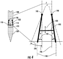
- Fig. 4 shows another cross-section elevation view of another example of the clad pipe (100) and core pipe (130) illustrating an example of applying an angle to the baffles (110), which alters the landing position of the clad glass stream onto the core glass stream in the lower pipe.
- the baffles (110) are configured to pivotally adjust in a manner that the baffles pivot about pivot points (190).
- the "drop” line (198) is a reference line that represents the inner most flow edge portion of the upper clad glass stream on the outer most edge of the baffle(s).
- the disclosed apparatus and method can be used to beneficially control or adjust, as needed, the drop line by altering the vertical, horizontal, or both, positions of one or both of the baffles (110).
- the pivoting of the baffles can be linked together by, for example, a slideable tie rod (410), spreader member, or like member or mechanism. Raising or lowering (double headed arrow; 420) the tie rod (410) by any suitable means (not shown) can cause the baffles to displace substantially equally outwardly or inwardly.
- the tie rod (410) can be actuated by one or more adjustment rods (120), which rods are shown in Figs. 1 and 2 .
- the pivoting action (e.g., 194) of the baffles (110) permits flow control and location control of the upper clad glass stream onto the lower core glass stream.
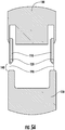
- Figs. 5A and 5B shows a cross-section elevation view of another example of the clad pipe (100) and core pipe (130) having vertically displaceable baffles (110).
- Fig. 5A shows another cross-section elevation view of another example of the clad pipe (100) and core pipe (130) having vertically displaceable baffles (110) having control rods (120) for adjusting the gap (140) between the lower end of the baffles and the top of the lower core pipe (130) or lower core glass stream (not shown).
- Fig. 5B shows the same cross-section elevation view of the clad pipe shown in Fig. 5A with the exception that the vertically displaceable baffles (110) are retracted into recesses of the upper pipe (100).
- control rods (120), or equivalent structure can be used for raising the baffles to adjust the gap (140) to have a larger dimension between the lower end of the baffles and the top of the lower core pipe (130) or lower core glass stream (not shown).
- the "drop" lines (198) in both Figs. 5A and 5B are approximately the same since there has been only vertical displacement of the baffles (110) and no pivotal or horizontal displacement of the baffles.
- Figs. 6A and 6B shows a cross-section elevation view of another example of the clad pipe (100) and core pipe (130) having displaceable baffles (110) that are both vertically and pivotally displaceable and adjustable.
- Fig. 6A shows the baffles (110) vertically retracted into recesses of the upper pipe (100) and extended pivotally outward providing the resulting relatively large gap (140) and widened or broadened landing angle (the specific ⁇ not shown).
- Fig. 6A shows the baffles (110) vertically retracted into recesses of the upper pipe (100) and extended pivotally outward providing the resulting relatively large gap (140) and widened or broadened landing angle (the specific ⁇ not shown).
- Fig. 6A shows the baffles (110) vertically retracted into recesses of the upper pipe (100) and extended pivotally outward providing the resulting relatively large gap (140) and widened or broadened landing angle (the specific ⁇ not shown).
- FIG. 6B shows the same apparatus having the baffles (110) vertically partially (shown) or fully extended downward from the recesses of the upper pipe (100) and pivotally drawn-in to provide the resulting relatively smaller gap (140), narrower landing angle (the specific ⁇ not shown), and "drop" lines (198) that are closer to the outer edge of the lower pipe (130).
- Fig. 7 shows a cross-section elevation view of another example of the clad pipe (100) having baffles (110) situated above the core pipe to manage the confluence of the molten glass streams.
- the lower core pipe contains molten glass in trough (155), which when deliberately filled beyond capacity produces an overflow core glass stream (150), which stream cascades downward under gravity.
- the upper clad pipe (100) having baffles (110) similarly produces and provides an overflow clad glass stream (160), which stream cascades downward until it contacts the core stream (150) at a point or region determined by the outer edge of the baffles (110).
- the combination (i.e., confluence) of clad and core glass melt streams produce two partial laminate streams (165).
- the partial laminate streams (165) can continue their descent separated from the other stream, for example, to provide single-sided laminated glass, or alternatively, the separated partial laminate streams (165) can be merged or converged to a laminate sheet (not shown) having a single core (150) and a clad layer (160) on both sides of the laminate sheet.
- a laminate sheet not shown
- clad and core are, in embodiments, relative and can be used interchangeably, for example, when a single-sided laminate is made with the disclosed apparatus and methods.
- Fig. 7 shows the core and the clad glass steams as having comparable thicknesses or volumes, i.e., 1:1 ratio.
- the respective the core (150) and clad layer (160) glass streams can have the same, similar, or dissimilar thicknesses or volumes.
- the core layer and a clad layers can have relative thicknesses ratio or volume ratio, for example, of from about 50:1, 20:1, 10:1; 5:1, 2:1, 1:1, 1:2, 1:10, 1:20, 1:50, and like ratios, including intermediate values and ranges.
- Fig. 8 shows a perspective view of aspects of the apparatus illustrated and described for Figs. 1 to 7 .
- the control rods (120), or equivalent structure can be used for raising the baffles to adjust the gap (140) to have a larger or smaller dimension, angle, or both, between the lower end of the baffles (110) and the top of the lower core pipe (130) or the lower core glass stream (150).
- the properly adjusted gap (140) provides reliable control of the confluence of the upper clad glass stream (140) and lower core glass stream (150).
- the baffles can be moveable plates located beneath or within the lower portion of the upper pipe.
- the plate material can include any suitable material, for example, platinum, various ceramics, high temperature metals, and like materials, or combinations thereof.
- At each end of the baffles are optionally rods that can, for example, extend beyond the exterior housing of the apparatus for the purpose of convenient adjustment.
- the gap between the bottom end of the baffles and the top of the lower pipe can be altered and the uniformity of the gap can be easily maintained or controllably changed using the adjustment rods.
- the baffles can be adjusted to correct glass flow and lamination characteristics of the resulting laminate.
- this condition can be corrected by changing the gap by appropriate adjustment of one or both of the baffle members.
- the gap (140) formed by the separation dimension between the ends of the baffles (110) situated at or in the upper clad pipe (100) and the lower pipe can be adjusted or advantageously changed.
- Increasing the size of the gap can be accomplished by, for example, holding both the upper clad pipe (100) and the lower core pipe (130) in a fixed position and having relative movement of the baffle(s) (110) away from the lower core pipe (130).
- the baffle (110) can be moved or adjusted vertically and away from the lower core pipe (130), that is, upward and away from the lower core pipe (130) by, for example, retracting the pair of baffles (110) into the body of the upper clad pipe (100).
- the decreasing the size of the gap (140) can be accomplished by holding both the upper clad pipe (100) and the lower core pipe (130) in a constant or fixed position and having relative movement of the baffle(s) (110) toward the lower core pipe (130).
- the entire length or a portion of the baffle (110) can be moved upwardly or downwardly from an initial vertical position to alter or adjust the gap (140) by any suitable mechanism, such as a remotely situated servo motor connected to screw-lifter, which is in turn be connected to a portion of the baffle (110) or paired baffles, such as by using the adjustment or control rod (120).
- the end of the baffle (110) can be moved outwardly from an initial vertical orientation to alter or adjust the landing angle ( ⁇ ) by any suitable mechanism, such as a spreader mechanism (410) situated between a pair of adjacent baffles (110).
- the baffles (110) can be adjusted in tandem or at the same time and by the same amount.
- the adjacent baffles (110) can be adjusted separately or independently of the other baffle in the pair.
- the adjacent baffles (110) can be both gap-adjusted (i.e., vertically) and landing-angle adjusted (i.e., horizontally), simultaneously or sequentially, depending for example, on the adjustment mechanism selected.
- a suitable mechanism for adjusting both the gap and the landing-angle can be, for example, a structure that resembles or can be modeled after a fixed wing airplane's flap adjustments including both extension-retraction relative motion and for angle-of-attack relative motion.
- another suitable mechanism for adjusting either or both the gap and the landing-angle can be, for example, a flexible boot structure that can be raised or lowered to adjust the gap dimension, and controllably expanded or contracted to achieve the desired adjustment in the landing angle.
- the expansion or contraction of the boot can be achieved, for example, by external or internal mechanical, pneumatic, hydraulic, and like forces or pressure changes, or combinations thereof, within the boot.
- changing the gap i.e., the separation dimension
- changing the gap causes a change in the velocity of the molten glass or melt flowing from the upper clad pipe onto the molten glass melt flowing from the lower core pipe.
- increasing the gap (140) separation dimension causes a relative increase in the flow velocity of the glass melt flowing from the upper clad pipe onto the lower melt flow.
- a decrease in the gap separation dimension typically causes a relative decrease in the flow velocity of the glass melt flowing from the upper clad pipe onto the lower melt flow.
- the clad glass stream if at the point of junction, the clad glass stream is faster than the core glass stream, the clad glass stream will begin to lap creating a "piling effect". This can have an impact on both the apparent glass mass distribution along the length of the pipe and the apparent glass mass distribution along the line of draw. This can cause sheet thickness variations across the draw and down the draw.
- a secondary issue can be the high potential for trapping air within the clad, core, or both, or between the clad and core layers, which can create seeds at the interface between the two different glass layers. This secondary issue can also be corrected by changing the gap, for example reducing the speed of the upper clad glass flow. Slowing the speed of the upper clad glass flow can be achieved by, for example, reducing the relative gap size.
- the pipes there can be situations when one of the pipes needs to be tilted to account for flow or viscosity changes due to altering process parameters.
- the tilt can cause a non-uniform gap between the two pipes. If the distance between the two pipes is not uniform, velocity non-uniformity can occur down the length of the pipe, causing the above-mentioned issues.
- the issues can be cured or circumvented with the disclosed apparatus and method of making.
- the relative tilt non-uniformity condition is typically not an issue with a single fusion pipe.
Landscapes
- Chemical & Material Sciences (AREA)
- Engineering & Computer Science (AREA)
- Materials Engineering (AREA)
- Organic Chemistry (AREA)
- Joining Of Glass To Other Materials (AREA)
Claims (13)
- Appareil pour former une feuille de verre stratifié, comprenant :un tuyau inférieur (130) fournissant un premier courant de liquide (150) qui forme le noyau du stratifié ;un premier tuyau supérieur (100) comportant une paire de chicanes réglables (110) situées entre le fond du tuyau supérieur et le dessus du tuyau inférieur (130),le premier tuyau supérieur (100) fournit un second courant de verre liquide (160) sur le premier courant de verre liquide (150) qui forme la gaine du stratifié sur le noyau du stratifié,les chicanes réglables (110) étant séparées du tuyau inférieur (130) par un espace (140), où les chicanes réglables s'ajustent verticalement pour contrôler la dimension de séparation de l'espace entre les chicanes réglables (110) du tuyau supérieur (100) et le dessus du tuyau inférieur (130),les chicanes réglables (110) s'ajustent de manière angulaire pour contrôler l'angle d'atterrissage (Φ) de la seconde masse fondue de verre de trop-plein sur la première masse fondue de verre de trop-plein ou les chicanes réglables (110) s'ajustent de manière angulaire et verticale.
- Appareil selon la revendication 1, où les chicanes réglables (110) s'ajustent de manière verticale pour contrôler la dimension de séparation de l'espace (140) entre les chicanes réglables du tuyau supérieur (100) et le dessus du tuyau inférieur (130).
- Appareil des revendications 1 ou 2, où les chicanes réglables (110) s'ajustent de manière angulaire pour contrôler l'angle d'atterrissage (Φ) du second courant de verre liquide (160) sur le premier courant de verre liquide (150).
- Appareil selon l'une quelconque des revendications 1 à 3, dans lequel les chicanes réglables (110) sont situées dans la partie inférieure du premier tuyau supérieur (100) et s'étendent vers le bas vers le dessus du tuyau inférieur (130).
- Appareil selon l'une quelconque des revendications 1 à 4, dans lequel l'orientation spatiale du tuyau inférieur (130) par rapport au tuyau supérieur (100) est fixe.
- Appareil selon l'une quelconque des revendications 1 à 5, où chacune des chicanes réglables (110) est connectée au tuyau supérieur (100) à une extrémité et chacune des chicanes réglables (110) possède au moins une tige de réglage (120) près de l'extrémité d'espace pour ajuster la dimension de l'espace (140).
- Appareil selon l'une quelconque des revendications 1 à 6, dans lequel l'alimentation en verre fondu qui alimente le tuyau inférieur (130) et le tuyau supérieur (100) provient de la même extrémité ou d'extrémités opposées des tuyaux.
- Appareil selon l'une quelconque des revendications 1 à 7, dans lequel une chicane de la paire de chicanes réglables (110) est positionnée différemment de l'autre chicane de la paire pour fournir une différence d'écoulement sur un déversoir du tuyau supérieur (100) par rapport à l'autre déversoir du tuyau supérieur (100), lequel écoulement différentiel fournit une feuille de verre stratifié ayant une gaine plus épaisse sur un côté du verre de noyau et une gaine plus mince sur l'autre côté du verre de noyau.
- Appareil selon l'une quelconque des revendications 1 à 8, comprenant en outre une pluralité de tuyaux supérieurs (100), chaque premier tuyau supérieur comportant une paire de chicanes réglables (110) situées entre le fond de chaque tuyau supérieur supplémentaire (100) et le dessus d'un tuyau inférieur précédent (130), et chaque tuyau supérieur supplémentaire fournit (100) un courant de verre liquide supplémentaire (160) sur le courant de verre liquide précédent qui forme une couche de gaine supplémentaire sur un ou les deux côtés du stratifié.
- Appareil selon l'une quelconque des revendications 1 à 9, dans lequel la dimension de séparation de l'espace (140) entre les chicanes réglables (110) et le tuyau inférieur (130) est à égale distance sur toute l'étendue de l'espace, la dimension de séparation de l'espace entre les chicanes réglables (110) et le tuyau inférieur (130) est non équidistante sur toute l'étendue de l'espace, ou une combinaison de ces éléments.
- Procédé de formation d'une feuille de verre stratifié dans l'appareil selon la revendication 1, comprenant :l'écoulement d'un premier courant de liquide (150) au-dessus du tuyau inférieur (130) pour former le noyau du stratifié; l'écoulement d'un second courant de liquide (160) au-dessus du tuyau supérieur (100), puis la paire de chicanes réglables (110), et puis sur le premier courant de liquide (150) pour former la gaine du stratifié sur le noyau du stratifié.
- Procédé selon la revendication 11 comprenant en outre le réglage des chicanes réglables (110) pour modifier l'espace (140), l'angle d'atterrissage (Φ) ou des combinaisons de ceux-ci, du second courant de liquide (160) sur le premier courant de liquide (150).
- Procédé selon l'une quelconque des revendications 11 à 12, comprenant en outre une pluralité de tuyaux supérieurs (100) avec une paire de chicanes réglables (110) empilés au-dessus du tuyau supérieur (130) pour fournir une feuille de verre stratifié où le nombre d'addition de couches correspond au double du nombre total de tuyaux supérieurs.
Applications Claiming Priority (2)
| Application Number | Priority Date | Filing Date | Title |
|---|---|---|---|
| US13/479,701 US8646291B2 (en) | 2012-05-24 | 2012-05-24 | Apparatus and method for control of glass streams in laminate fusion |
| PCT/US2013/041804 WO2013177032A1 (fr) | 2012-05-24 | 2013-05-20 | Appareil et méthode de régulation de flux de verre pour la fusion de verre feuilleté |
Publications (3)
| Publication Number | Publication Date |
|---|---|
| EP2855151A1 EP2855151A1 (fr) | 2015-04-08 |
| EP2855151A4 EP2855151A4 (fr) | 2016-03-16 |
| EP2855151B1 true EP2855151B1 (fr) | 2017-05-03 |
Family
ID=49620516
Family Applications (1)
| Application Number | Title | Priority Date | Filing Date |
|---|---|---|---|
| EP13793400.6A Not-in-force EP2855151B1 (fr) | 2012-05-24 | 2013-05-20 | Appareil et méthode de régulation de flux de verre pour la fusion de verre feuilleté |
Country Status (8)
| Country | Link |
|---|---|
| US (1) | US8646291B2 (fr) |
| EP (1) | EP2855151B1 (fr) |
| JP (1) | JP6149310B2 (fr) |
| KR (1) | KR102100993B1 (fr) |
| CN (1) | CN104470721B (fr) |
| IN (1) | IN2014DN09292A (fr) |
| TW (1) | TWI586539B (fr) |
| WO (1) | WO2013177032A1 (fr) |
Families Citing this family (18)
| Publication number | Priority date | Publication date | Assignee | Title |
|---|---|---|---|---|
| US10011512B2 (en) | 2012-05-24 | 2018-07-03 | Corning Incorporated | Suspension and control system for glass laminate fusion |
| US9556052B2 (en) * | 2012-05-24 | 2017-01-31 | Corning Incorporated | Laminate fusion draw apparatus and method of use thereof |
| US9434632B2 (en) | 2013-02-26 | 2016-09-06 | Corning Incorporated | Glass forming apparatus and method |
| TWI627141B (zh) | 2013-04-30 | 2018-06-21 | 康寧公司 | 用於沿等壓管堰控制熔融玻璃流的設備與方法 |
| TW201444772A (zh) * | 2013-05-31 | 2014-12-01 | Fortune Tech Man Corp | 複合式玻璃成型系統 |
| EP3074351B1 (fr) * | 2013-11-30 | 2019-05-29 | Corning Inc. | Système de suspension et de commande de la fusion de verre feuilleté |
| US9456817B2 (en) | 2014-04-08 | 2016-10-04 | DePuy Synthes Products, Inc. | Methods and devices for spinal correction |
| WO2015164569A1 (fr) * | 2014-04-25 | 2015-10-29 | Corning Incorporated | Appareil et procédé de fabrication d'articles en verre composite |
| US10144198B2 (en) | 2014-05-02 | 2018-12-04 | Corning Incorporated | Strengthened glass and compositions therefor |
| TWI667130B (zh) | 2014-06-26 | 2019-08-01 | 美商康寧公司 | 絕緣玻璃單元 |
| US9556051B2 (en) | 2014-09-22 | 2017-01-31 | Corning Incorporated | Methods for controlling the thickness wedge in a glass ribbon |
| CN107531538A (zh) * | 2015-05-01 | 2018-01-02 | 康宁股份有限公司 | 用于控制玻璃片厚度的方法和设备 |
| US20180327299A1 (en) * | 2015-11-20 | 2018-11-15 | Corning Incorporated | Apparatus and method for forming glass ribbon |
| EP3377453A1 (fr) * | 2015-11-20 | 2018-09-26 | Corning Incorporated | Rubans de verre feuilleté et appareils pour former des rubans de verre feuilleté |
| WO2019126521A1 (fr) | 2017-12-21 | 2019-06-27 | Corning Incorporated | Unité de verre isolée multicouche comprenant une couche de verre à faible cte |
| KR20210042340A (ko) * | 2018-08-10 | 2021-04-19 | 코닝 인코포레이티드 | 라미네이트 유리 시트들을 형성하는 방법 및 장치 |
| CN114524605B (zh) * | 2022-03-14 | 2023-09-12 | 成都中光电科技有限公司 | 玻璃生产的溢流设备 |
| JP7734766B2 (ja) * | 2022-12-22 | 2025-09-05 | 彩虹顕示器件股▲ふん▼有限公司 | オーバーフローレンガの引き出し量を向上させる縁板制御方法及びシステム |
Family Cites Families (25)
| Publication number | Priority date | Publication date | Assignee | Title |
|---|---|---|---|---|
| US1673907A (en) * | 1928-06-19 | of toledo | ||
| US1734964A (en) * | 1921-11-17 | 1929-11-12 | Danner Edward | Method and apparatus for manufacturing continuous glassware |
| US1734965A (en) * | 1921-12-05 | 1929-11-12 | Danner Edward | Method and apparatus for forming glassware |
| US1623051A (en) * | 1925-05-16 | 1927-04-05 | Libbey Owens Sheet Glass Co | Multiple-sheet-flowing apparatus |
| US1836394A (en) * | 1927-09-22 | 1931-12-15 | Libbey Owens Ford Glass Co | Process and apparatus for producing sheet glass |
| US3607182A (en) * | 1970-07-29 | 1971-09-21 | Corning Glass Works | Method and apparatus for removal of bubbles from sheet glass overflow forming surfaces |
| DE2913217A1 (de) * | 1979-04-03 | 1980-10-23 | Agfa Ag | Verfahren und vorrichtung zum gleichzeitigen auftragen mehrerer schichten auf bewegte gegenstaende insbesondere bahnen |
| US4214886A (en) * | 1979-04-05 | 1980-07-29 | Corning Glass Works | Forming laminated sheet glass |
| US4204027A (en) * | 1979-04-05 | 1980-05-20 | Corning Glass Works | Photochromic sheet glass process |
| JPS6036339A (ja) * | 1983-06-06 | 1985-02-25 | ボリス・エル・ルドイ | ガラス製品連続製造装置 |
| US4525194A (en) * | 1983-06-06 | 1985-06-25 | Rudoi Boris L | Apparatus for simultaneous production of double glass panels |
| US4678719A (en) | 1984-09-13 | 1987-07-07 | Allegheny Ludlum Corporation | Method and apparatus for continuous casting of crystalline strip |
| JPH0346836A (ja) | 1989-07-14 | 1991-02-28 | Mitsubishi Electric Corp | 自動車電話機 |
| JP3046836B2 (ja) | 1990-11-30 | 2000-05-29 | 東芝セラミックス株式会社 | 石英ガラス管製造装置 |
| US6196026B1 (en) * | 1998-03-18 | 2001-03-06 | Corning Incorporated | Method of making a glass array plate with closure |
| JP2000344534A (ja) | 1999-06-04 | 2000-12-12 | Sony Corp | ガラスロッド製造装置 |
| US6748765B2 (en) * | 2000-05-09 | 2004-06-15 | Richard B. Pitbladdo | Overflow downdraw glass forming method and apparatus |
| US20040093900A1 (en) * | 2002-11-15 | 2004-05-20 | Fredholm Allan M. | Apparatus and method for producing sheets of glass presenting at least one face of very high surface quality |
| US7514149B2 (en) * | 2003-04-04 | 2009-04-07 | Corning Incorporated | High-strength laminated sheet for optical applications |
| US8042361B2 (en) * | 2004-07-20 | 2011-10-25 | Corning Incorporated | Overflow downdraw glass forming method and apparatus |
| US7201965B2 (en) * | 2004-12-13 | 2007-04-10 | Corning Incorporated | Glass laminate substrate having enhanced impact and static loading resistance |
| KR101224666B1 (ko) | 2005-02-24 | 2013-01-21 | 코닝 인코포레이티드 | 유리 시트를 제조하는 장치 및 방법 |
| US8007913B2 (en) * | 2006-02-10 | 2011-08-30 | Corning Incorporated | Laminated glass articles and methods of making thereof |
| EP2065345A1 (fr) * | 2007-11-29 | 2009-06-03 | Corning Incorporated | Appareil et procédé de production de plaques de verre présentant au moins une face de qualité de surface très élevée |
| US8397538B2 (en) * | 2009-02-26 | 2013-03-19 | Corning Incorporated | Apparatus and method for drawing a ribbon of glass |
-
2012
- 2012-05-24 US US13/479,701 patent/US8646291B2/en not_active Expired - Fee Related
-
2013
- 2013-05-20 IN IN9292DEN2014 patent/IN2014DN09292A/en unknown
- 2013-05-20 CN CN201380027217.5A patent/CN104470721B/zh not_active Expired - Fee Related
- 2013-05-20 JP JP2015514084A patent/JP6149310B2/ja not_active Expired - Fee Related
- 2013-05-20 KR KR1020147035378A patent/KR102100993B1/ko not_active Expired - Fee Related
- 2013-05-20 EP EP13793400.6A patent/EP2855151B1/fr not_active Not-in-force
- 2013-05-20 WO PCT/US2013/041804 patent/WO2013177032A1/fr not_active Ceased
- 2013-05-24 TW TW102118510A patent/TWI586539B/zh not_active IP Right Cessation
Also Published As
| Publication number | Publication date |
|---|---|
| KR20150018820A (ko) | 2015-02-24 |
| WO2013177032A1 (fr) | 2013-11-28 |
| IN2014DN09292A (fr) | 2015-07-10 |
| EP2855151A1 (fr) | 2015-04-08 |
| CN104470721B (zh) | 2016-05-25 |
| CN104470721A (zh) | 2015-03-25 |
| JP2015520108A (ja) | 2015-07-16 |
| KR102100993B1 (ko) | 2020-04-16 |
| JP6149310B2 (ja) | 2017-06-21 |
| TW201400287A (zh) | 2014-01-01 |
| EP2855151A4 (fr) | 2016-03-16 |
| US8646291B2 (en) | 2014-02-11 |
| US20130312459A1 (en) | 2013-11-28 |
| TWI586539B (zh) | 2017-06-11 |
Similar Documents
| Publication | Publication Date | Title |
|---|---|---|
| EP2855151B1 (fr) | Appareil et méthode de régulation de flux de verre pour la fusion de verre feuilleté | |
| US9796616B2 (en) | Apparatus and method for producing laminated glass sheet | |
| US11639305B2 (en) | Apparatus and method for molten glass flow control along an isopipe weir | |
| US8973402B2 (en) | Overflow down-draw with improved glass melt velocity and thickness distribution | |
| JP6316424B2 (ja) | 積層ガラスシート製造装置および方法 | |
| JP6339180B2 (ja) | 積層溶融延伸装置およびその使用法 | |
| EP2961701B1 (fr) | Appareil et procédé de formation d'une feuille de verre avec un coeur et une gaine vitreuses | |
| KR20160063355A (ko) | 유리 라미네이트 시트의 외층을 형성하기 위한 장치 및 방법 | |
| KR102733497B1 (ko) | 적층 유리 리본 및 적층 유리 리본의 제조 장치 | |
| JP6457520B2 (ja) | ガラス積層体溶融のための懸架および制御システム | |
| JP2016538223A5 (fr) | ||
| US20160297702A1 (en) | Suspension and control system for glass laminate fusion |
Legal Events
| Date | Code | Title | Description |
|---|---|---|---|
| PUAI | Public reference made under article 153(3) epc to a published international application that has entered the european phase |
Free format text: ORIGINAL CODE: 0009012 |
|
| 17P | Request for examination filed |
Effective date: 20141218 |
|
| AK | Designated contracting states |
Kind code of ref document: A1 Designated state(s): AL AT BE BG CH CY CZ DE DK EE ES FI FR GB GR HR HU IE IS IT LI LT LU LV MC MK MT NL NO PL PT RO RS SE SI SK SM TR |
|
| AX | Request for extension of the european patent |
Extension state: BA ME |
|
| DAX | Request for extension of the european patent (deleted) | ||
| RA4 | Supplementary search report drawn up and despatched (corrected) |
Effective date: 20160215 |
|
| RIC1 | Information provided on ipc code assigned before grant |
Ipc: C03B 17/02 20060101ALI20160209BHEP Ipc: B32B 17/00 20060101ALI20160209BHEP Ipc: C03B 17/06 20060101ALI20160209BHEP Ipc: B32B 37/00 20060101AFI20160209BHEP |
|
| GRAP | Despatch of communication of intention to grant a patent |
Free format text: ORIGINAL CODE: EPIDOSNIGR1 |
|
| INTG | Intention to grant announced |
Effective date: 20161201 |
|
| GRAS | Grant fee paid |
Free format text: ORIGINAL CODE: EPIDOSNIGR3 |
|
| GRAA | (expected) grant |
Free format text: ORIGINAL CODE: 0009210 |
|
| AK | Designated contracting states |
Kind code of ref document: B1 Designated state(s): AL AT BE BG CH CY CZ DE DK EE ES FI FR GB GR HR HU IE IS IT LI LT LU LV MC MK MT NL NO PL PT RO RS SE SI SK SM TR |
|
| REG | Reference to a national code |
Ref country code: GB Ref legal event code: FG4D |
|
| REG | Reference to a national code |
Ref country code: AT Ref legal event code: REF Ref document number: 889528 Country of ref document: AT Kind code of ref document: T Effective date: 20170515 Ref country code: CH Ref legal event code: EP |
|
| REG | Reference to a national code |
Ref country code: FR Ref legal event code: PLFP Year of fee payment: 5 |
|
| REG | Reference to a national code |
Ref country code: IE Ref legal event code: FG4D |
|
| REG | Reference to a national code |
Ref country code: DE Ref legal event code: R096 Ref document number: 602013020722 Country of ref document: DE |
|
| REG | Reference to a national code |
Ref country code: NL Ref legal event code: MP Effective date: 20170503 |
|
| REG | Reference to a national code |
Ref country code: AT Ref legal event code: MK05 Ref document number: 889528 Country of ref document: AT Kind code of ref document: T Effective date: 20170503 |
|
| REG | Reference to a national code |
Ref country code: LT Ref legal event code: MG4D |
|
| PG25 | Lapsed in a contracting state [announced via postgrant information from national office to epo] |
Ref country code: FI Free format text: LAPSE BECAUSE OF FAILURE TO SUBMIT A TRANSLATION OF THE DESCRIPTION OR TO PAY THE FEE WITHIN THE PRESCRIBED TIME-LIMIT Effective date: 20170503 Ref country code: ES Free format text: LAPSE BECAUSE OF FAILURE TO SUBMIT A TRANSLATION OF THE DESCRIPTION OR TO PAY THE FEE WITHIN THE PRESCRIBED TIME-LIMIT Effective date: 20170503 Ref country code: HR Free format text: LAPSE BECAUSE OF FAILURE TO SUBMIT A TRANSLATION OF THE DESCRIPTION OR TO PAY THE FEE WITHIN THE PRESCRIBED TIME-LIMIT Effective date: 20170503 Ref country code: LT Free format text: LAPSE BECAUSE OF FAILURE TO SUBMIT A TRANSLATION OF THE DESCRIPTION OR TO PAY THE FEE WITHIN THE PRESCRIBED TIME-LIMIT Effective date: 20170503 Ref country code: NO Free format text: LAPSE BECAUSE OF FAILURE TO SUBMIT A TRANSLATION OF THE DESCRIPTION OR TO PAY THE FEE WITHIN THE PRESCRIBED TIME-LIMIT Effective date: 20170803 Ref country code: GR Free format text: LAPSE BECAUSE OF FAILURE TO SUBMIT A TRANSLATION OF THE DESCRIPTION OR TO PAY THE FEE WITHIN THE PRESCRIBED TIME-LIMIT Effective date: 20170804 Ref country code: AT Free format text: LAPSE BECAUSE OF FAILURE TO SUBMIT A TRANSLATION OF THE DESCRIPTION OR TO PAY THE FEE WITHIN THE PRESCRIBED TIME-LIMIT Effective date: 20170503 |
|
| PG25 | Lapsed in a contracting state [announced via postgrant information from national office to epo] |
Ref country code: SE Free format text: LAPSE BECAUSE OF FAILURE TO SUBMIT A TRANSLATION OF THE DESCRIPTION OR TO PAY THE FEE WITHIN THE PRESCRIBED TIME-LIMIT Effective date: 20170503 Ref country code: BG Free format text: LAPSE BECAUSE OF FAILURE TO SUBMIT A TRANSLATION OF THE DESCRIPTION OR TO PAY THE FEE WITHIN THE PRESCRIBED TIME-LIMIT Effective date: 20170803 Ref country code: LV Free format text: LAPSE BECAUSE OF FAILURE TO SUBMIT A TRANSLATION OF THE DESCRIPTION OR TO PAY THE FEE WITHIN THE PRESCRIBED TIME-LIMIT Effective date: 20170503 Ref country code: IS Free format text: LAPSE BECAUSE OF FAILURE TO SUBMIT A TRANSLATION OF THE DESCRIPTION OR TO PAY THE FEE WITHIN THE PRESCRIBED TIME-LIMIT Effective date: 20170903 Ref country code: PL Free format text: LAPSE BECAUSE OF FAILURE TO SUBMIT A TRANSLATION OF THE DESCRIPTION OR TO PAY THE FEE WITHIN THE PRESCRIBED TIME-LIMIT Effective date: 20170503 Ref country code: RS Free format text: LAPSE BECAUSE OF FAILURE TO SUBMIT A TRANSLATION OF THE DESCRIPTION OR TO PAY THE FEE WITHIN THE PRESCRIBED TIME-LIMIT Effective date: 20170503 Ref country code: NL Free format text: LAPSE BECAUSE OF FAILURE TO SUBMIT A TRANSLATION OF THE DESCRIPTION OR TO PAY THE FEE WITHIN THE PRESCRIBED TIME-LIMIT Effective date: 20170503 |
|
| REG | Reference to a national code |
Ref country code: CH Ref legal event code: PL |
|
| PG25 | Lapsed in a contracting state [announced via postgrant information from national office to epo] |
Ref country code: SK Free format text: LAPSE BECAUSE OF FAILURE TO SUBMIT A TRANSLATION OF THE DESCRIPTION OR TO PAY THE FEE WITHIN THE PRESCRIBED TIME-LIMIT Effective date: 20170503 Ref country code: EE Free format text: LAPSE BECAUSE OF FAILURE TO SUBMIT A TRANSLATION OF THE DESCRIPTION OR TO PAY THE FEE WITHIN THE PRESCRIBED TIME-LIMIT Effective date: 20170503 Ref country code: CZ Free format text: LAPSE BECAUSE OF FAILURE TO SUBMIT A TRANSLATION OF THE DESCRIPTION OR TO PAY THE FEE WITHIN THE PRESCRIBED TIME-LIMIT Effective date: 20170503 Ref country code: DK Free format text: LAPSE BECAUSE OF FAILURE TO SUBMIT A TRANSLATION OF THE DESCRIPTION OR TO PAY THE FEE WITHIN THE PRESCRIBED TIME-LIMIT Effective date: 20170503 Ref country code: RO Free format text: LAPSE BECAUSE OF FAILURE TO SUBMIT A TRANSLATION OF THE DESCRIPTION OR TO PAY THE FEE WITHIN THE PRESCRIBED TIME-LIMIT Effective date: 20170503 |
|
| REG | Reference to a national code |
Ref country code: DE Ref legal event code: R097 Ref document number: 602013020722 Country of ref document: DE |
|
| REG | Reference to a national code |
Ref country code: IE Ref legal event code: MM4A |
|
| PG25 | Lapsed in a contracting state [announced via postgrant information from national office to epo] |
Ref country code: SM Free format text: LAPSE BECAUSE OF FAILURE TO SUBMIT A TRANSLATION OF THE DESCRIPTION OR TO PAY THE FEE WITHIN THE PRESCRIBED TIME-LIMIT Effective date: 20170503 Ref country code: IT Free format text: LAPSE BECAUSE OF FAILURE TO SUBMIT A TRANSLATION OF THE DESCRIPTION OR TO PAY THE FEE WITHIN THE PRESCRIBED TIME-LIMIT Effective date: 20170503 Ref country code: CH Free format text: LAPSE BECAUSE OF NON-PAYMENT OF DUE FEES Effective date: 20170531 Ref country code: LI Free format text: LAPSE BECAUSE OF NON-PAYMENT OF DUE FEES Effective date: 20170531 |
|
| PLBE | No opposition filed within time limit |
Free format text: ORIGINAL CODE: 0009261 |
|
| STAA | Information on the status of an ep patent application or granted ep patent |
Free format text: STATUS: NO OPPOSITION FILED WITHIN TIME LIMIT |
|
| PG25 | Lapsed in a contracting state [announced via postgrant information from national office to epo] |
Ref country code: LU Free format text: LAPSE BECAUSE OF NON-PAYMENT OF DUE FEES Effective date: 20170520 |
|
| 26N | No opposition filed |
Effective date: 20180206 |
|
| REG | Reference to a national code |
Ref country code: FR Ref legal event code: PLFP Year of fee payment: 6 |
|
| REG | Reference to a national code |
Ref country code: BE Ref legal event code: MM Effective date: 20170531 |
|
| PG25 | Lapsed in a contracting state [announced via postgrant information from national office to epo] |
Ref country code: IE Free format text: LAPSE BECAUSE OF NON-PAYMENT OF DUE FEES Effective date: 20170520 |
|
| PGFP | Annual fee paid to national office [announced via postgrant information from national office to epo] |
Ref country code: GB Payment date: 20180328 Year of fee payment: 6 |
|
| PG25 | Lapsed in a contracting state [announced via postgrant information from national office to epo] |
Ref country code: SI Free format text: LAPSE BECAUSE OF FAILURE TO SUBMIT A TRANSLATION OF THE DESCRIPTION OR TO PAY THE FEE WITHIN THE PRESCRIBED TIME-LIMIT Effective date: 20170503 |
|
| PGFP | Annual fee paid to national office [announced via postgrant information from national office to epo] |
Ref country code: DE Payment date: 20180507 Year of fee payment: 6 |
|
| PG25 | Lapsed in a contracting state [announced via postgrant information from national office to epo] |
Ref country code: BE Free format text: LAPSE BECAUSE OF NON-PAYMENT OF DUE FEES Effective date: 20170531 |
|
| PG25 | Lapsed in a contracting state [announced via postgrant information from national office to epo] |
Ref country code: MT Free format text: LAPSE BECAUSE OF NON-PAYMENT OF DUE FEES Effective date: 20170520 |
|
| PG25 | Lapsed in a contracting state [announced via postgrant information from national office to epo] |
Ref country code: HU Free format text: LAPSE BECAUSE OF FAILURE TO SUBMIT A TRANSLATION OF THE DESCRIPTION OR TO PAY THE FEE WITHIN THE PRESCRIBED TIME-LIMIT; INVALID AB INITIO Effective date: 20130520 Ref country code: MC Free format text: LAPSE BECAUSE OF FAILURE TO SUBMIT A TRANSLATION OF THE DESCRIPTION OR TO PAY THE FEE WITHIN THE PRESCRIBED TIME-LIMIT Effective date: 20170503 |
|
| PG25 | Lapsed in a contracting state [announced via postgrant information from national office to epo] |
Ref country code: CY Free format text: LAPSE BECAUSE OF FAILURE TO SUBMIT A TRANSLATION OF THE DESCRIPTION OR TO PAY THE FEE WITHIN THE PRESCRIBED TIME-LIMIT Effective date: 20170503 |
|
| PG25 | Lapsed in a contracting state [announced via postgrant information from national office to epo] |
Ref country code: MK Free format text: LAPSE BECAUSE OF FAILURE TO SUBMIT A TRANSLATION OF THE DESCRIPTION OR TO PAY THE FEE WITHIN THE PRESCRIBED TIME-LIMIT Effective date: 20170503 |
|
| REG | Reference to a national code |
Ref country code: DE Ref legal event code: R119 Ref document number: 602013020722 Country of ref document: DE |
|
| GBPC | Gb: european patent ceased through non-payment of renewal fee |
Effective date: 20190520 |
|
| PG25 | Lapsed in a contracting state [announced via postgrant information from national office to epo] |
Ref country code: TR Free format text: LAPSE BECAUSE OF FAILURE TO SUBMIT A TRANSLATION OF THE DESCRIPTION OR TO PAY THE FEE WITHIN THE PRESCRIBED TIME-LIMIT Effective date: 20170503 |
|
| PG25 | Lapsed in a contracting state [announced via postgrant information from national office to epo] |
Ref country code: GB Free format text: LAPSE BECAUSE OF NON-PAYMENT OF DUE FEES Effective date: 20190520 Ref country code: DE Free format text: LAPSE BECAUSE OF NON-PAYMENT OF DUE FEES Effective date: 20191203 |
|
| PG25 | Lapsed in a contracting state [announced via postgrant information from national office to epo] |
Ref country code: PT Free format text: LAPSE BECAUSE OF FAILURE TO SUBMIT A TRANSLATION OF THE DESCRIPTION OR TO PAY THE FEE WITHIN THE PRESCRIBED TIME-LIMIT Effective date: 20170503 |
|
| PG25 | Lapsed in a contracting state [announced via postgrant information from national office to epo] |
Ref country code: AL Free format text: LAPSE BECAUSE OF FAILURE TO SUBMIT A TRANSLATION OF THE DESCRIPTION OR TO PAY THE FEE WITHIN THE PRESCRIBED TIME-LIMIT Effective date: 20170503 |
|
| PGFP | Annual fee paid to national office [announced via postgrant information from national office to epo] |
Ref country code: FR Payment date: 20200421 Year of fee payment: 8 |
|
| PG25 | Lapsed in a contracting state [announced via postgrant information from national office to epo] |
Ref country code: FR Free format text: LAPSE BECAUSE OF NON-PAYMENT OF DUE FEES Effective date: 20210531 |