EP2854645B1 - Bewegungsschichtzerlegungungskalibrierung von röntgen-ct-bildgebungsvorrichtungen - Google Patents
Bewegungsschichtzerlegungungskalibrierung von röntgen-ct-bildgebungsvorrichtungen Download PDFInfo
- Publication number
- EP2854645B1 EP2854645B1 EP13737381.7A EP13737381A EP2854645B1 EP 2854645 B1 EP2854645 B1 EP 2854645B1 EP 13737381 A EP13737381 A EP 13737381A EP 2854645 B1 EP2854645 B1 EP 2854645B1
- Authority
- EP
- European Patent Office
- Prior art keywords
- ray
- elements
- gantry
- data
- correction
- Prior art date
- Legal status (The legal status is an assumption and is not a legal conclusion. Google has not performed a legal analysis and makes no representation as to the accuracy of the status listed.)
- Active
Links
- 238000000354 decomposition reaction Methods 0.000 title description 29
- 238000012937 correction Methods 0.000 claims description 52
- 238000005259 measurement Methods 0.000 claims description 30
- 238000003384 imaging method Methods 0.000 claims description 21
- 238000000034 method Methods 0.000 claims description 19
- 238000002591 computed tomography Methods 0.000 claims description 8
- 238000013461 design Methods 0.000 claims description 4
- 238000006073 displacement reaction Methods 0.000 claims 1
- 230000008901 benefit Effects 0.000 description 9
- 238000012545 processing Methods 0.000 description 8
- 230000009466 transformation Effects 0.000 description 7
- 230000008859 change Effects 0.000 description 6
- 230000006870 function Effects 0.000 description 5
- 230000000694 effects Effects 0.000 description 4
- 238000000844 transformation Methods 0.000 description 4
- 238000010521 absorption reaction Methods 0.000 description 3
- 238000004458 analytical method Methods 0.000 description 3
- 230000004075 alteration Effects 0.000 description 2
- 238000007408 cone-beam computed tomography Methods 0.000 description 2
- 238000013500 data storage Methods 0.000 description 2
- 238000004519 manufacturing process Methods 0.000 description 2
- 238000012986 modification Methods 0.000 description 2
- 230000004048 modification Effects 0.000 description 2
- 238000003672 processing method Methods 0.000 description 2
- 230000005855 radiation Effects 0.000 description 2
- 238000013519 translation Methods 0.000 description 2
- 230000014616 translation Effects 0.000 description 2
- 210000003484 anatomy Anatomy 0.000 description 1
- 238000002583 angiography Methods 0.000 description 1
- 230000000712 assembly Effects 0.000 description 1
- 238000000429 assembly Methods 0.000 description 1
- 238000004891 communication Methods 0.000 description 1
- 230000008602 contraction Effects 0.000 description 1
- 230000007613 environmental effect Effects 0.000 description 1
- 238000001914 filtration Methods 0.000 description 1
- 238000005286 illumination Methods 0.000 description 1
- 238000010191 image analysis Methods 0.000 description 1
- 230000006872 improvement Effects 0.000 description 1
- 238000010348 incorporation Methods 0.000 description 1
- 238000012423 maintenance Methods 0.000 description 1
- 238000012805 post-processing Methods 0.000 description 1
- 230000008569 process Effects 0.000 description 1
- 230000009467 reduction Effects 0.000 description 1
- 238000009877 rendering Methods 0.000 description 1
- 230000035945 sensitivity Effects 0.000 description 1
- 238000004088 simulation Methods 0.000 description 1
- 230000002277 temperature effect Effects 0.000 description 1
- 230000003442 weekly effect Effects 0.000 description 1
Images


Classifications
-
- A—HUMAN NECESSITIES
- A61—MEDICAL OR VETERINARY SCIENCE; HYGIENE
- A61B—DIAGNOSIS; SURGERY; IDENTIFICATION
- A61B6/00—Apparatus for radiation diagnosis, e.g. combined with radiation therapy equipment
- A61B6/58—Testing, adjusting or calibrating apparatus or devices for radiation diagnosis
- A61B6/582—Calibration
- A61B6/583—Calibration using calibration phantoms
- A61B6/584—Calibration using calibration phantoms determining position of components of the apparatus or device using images of the phantom
-
- A—HUMAN NECESSITIES
- A61—MEDICAL OR VETERINARY SCIENCE; HYGIENE
- A61B—DIAGNOSIS; SURGERY; IDENTIFICATION
- A61B6/00—Apparatus for radiation diagnosis, e.g. combined with radiation therapy equipment
- A61B6/40—Apparatus for radiation diagnosis, e.g. combined with radiation therapy equipment with arrangements for generating radiation specially adapted for radiation diagnosis
- A61B6/4035—Apparatus for radiation diagnosis, e.g. combined with radiation therapy equipment with arrangements for generating radiation specially adapted for radiation diagnosis the source being combined with a filter or grating
-
- A—HUMAN NECESSITIES
- A61—MEDICAL OR VETERINARY SCIENCE; HYGIENE
- A61B—DIAGNOSIS; SURGERY; IDENTIFICATION
- A61B6/00—Apparatus for radiation diagnosis, e.g. combined with radiation therapy equipment
- A61B6/42—Apparatus for radiation diagnosis, e.g. combined with radiation therapy equipment with arrangements for detecting radiation specially adapted for radiation diagnosis
- A61B6/4208—Apparatus for radiation diagnosis, e.g. combined with radiation therapy equipment with arrangements for detecting radiation specially adapted for radiation diagnosis characterised by using a particular type of detector
- A61B6/4233—Apparatus for radiation diagnosis, e.g. combined with radiation therapy equipment with arrangements for detecting radiation specially adapted for radiation diagnosis characterised by using a particular type of detector using matrix detectors
-
- A—HUMAN NECESSITIES
- A61—MEDICAL OR VETERINARY SCIENCE; HYGIENE
- A61B—DIAGNOSIS; SURGERY; IDENTIFICATION
- A61B6/00—Apparatus for radiation diagnosis, e.g. combined with radiation therapy equipment
- A61B6/44—Constructional features of apparatus for radiation diagnosis
- A61B6/4429—Constructional features of apparatus for radiation diagnosis related to the mounting of source units and detector units
- A61B6/4435—Constructional features of apparatus for radiation diagnosis related to the mounting of source units and detector units the source unit and the detector unit being coupled by a rigid structure
- A61B6/4441—Constructional features of apparatus for radiation diagnosis related to the mounting of source units and detector units the source unit and the detector unit being coupled by a rigid structure the rigid structure being a C-arm or U-arm
-
- A—HUMAN NECESSITIES
- A61—MEDICAL OR VETERINARY SCIENCE; HYGIENE
- A61B—DIAGNOSIS; SURGERY; IDENTIFICATION
- A61B6/00—Apparatus for radiation diagnosis, e.g. combined with radiation therapy equipment
- A61B6/52—Devices using data or image processing specially adapted for radiation diagnosis
- A61B6/5205—Devices using data or image processing specially adapted for radiation diagnosis involving processing of raw data to produce diagnostic data
-
- A—HUMAN NECESSITIES
- A61—MEDICAL OR VETERINARY SCIENCE; HYGIENE
- A61B—DIAGNOSIS; SURGERY; IDENTIFICATION
- A61B6/00—Apparatus for radiation diagnosis, e.g. combined with radiation therapy equipment
- A61B6/58—Testing, adjusting or calibrating apparatus or devices for radiation diagnosis
-
- A—HUMAN NECESSITIES
- A61—MEDICAL OR VETERINARY SCIENCE; HYGIENE
- A61B—DIAGNOSIS; SURGERY; IDENTIFICATION
- A61B6/00—Apparatus for radiation diagnosis, e.g. combined with radiation therapy equipment
- A61B6/58—Testing, adjusting or calibrating apparatus or devices for radiation diagnosis
- A61B6/582—Calibration
- A61B6/583—Calibration using calibration phantoms
-
- G—PHYSICS
- G01—MEASURING; TESTING
- G01N—INVESTIGATING OR ANALYSING MATERIALS BY DETERMINING THEIR CHEMICAL OR PHYSICAL PROPERTIES
- G01N23/00—Investigating or analysing materials by the use of wave or particle radiation, e.g. X-rays or neutrons, not covered by groups G01N3/00 – G01N17/00, G01N21/00 or G01N22/00
- G01N23/02—Investigating or analysing materials by the use of wave or particle radiation, e.g. X-rays or neutrons, not covered by groups G01N3/00 – G01N17/00, G01N21/00 or G01N22/00 by transmitting the radiation through the material
- G01N23/04—Investigating or analysing materials by the use of wave or particle radiation, e.g. X-rays or neutrons, not covered by groups G01N3/00 – G01N17/00, G01N21/00 or G01N22/00 by transmitting the radiation through the material and forming images of the material
- G01N23/046—Investigating or analysing materials by the use of wave or particle radiation, e.g. X-rays or neutrons, not covered by groups G01N3/00 – G01N17/00, G01N21/00 or G01N22/00 by transmitting the radiation through the material and forming images of the material using tomography, e.g. computed tomography [CT]
-
- G—PHYSICS
- G06—COMPUTING; CALCULATING OR COUNTING
- G06T—IMAGE DATA PROCESSING OR GENERATION, IN GENERAL
- G06T11/00—2D [Two Dimensional] image generation
- G06T11/003—Reconstruction from projections, e.g. tomography
- G06T11/005—Specific pre-processing for tomographic reconstruction, e.g. calibration, source positioning, rebinning, scatter correction, retrospective gating
-
- G—PHYSICS
- G21—NUCLEAR PHYSICS; NUCLEAR ENGINEERING
- G21K—TECHNIQUES FOR HANDLING PARTICLES OR IONISING RADIATION NOT OTHERWISE PROVIDED FOR; IRRADIATION DEVICES; GAMMA RAY OR X-RAY MICROSCOPES
- G21K1/00—Arrangements for handling particles or ionising radiation, e.g. focusing or moderating
- G21K1/02—Arrangements for handling particles or ionising radiation, e.g. focusing or moderating using diaphragms, collimators
- G21K1/025—Arrangements for handling particles or ionising radiation, e.g. focusing or moderating using diaphragms, collimators using multiple collimators, e.g. Bucky screens; other devices for eliminating undesired or dispersed radiation
-
- G—PHYSICS
- G21—NUCLEAR PHYSICS; NUCLEAR ENGINEERING
- G21K—TECHNIQUES FOR HANDLING PARTICLES OR IONISING RADIATION NOT OTHERWISE PROVIDED FOR; IRRADIATION DEVICES; GAMMA RAY OR X-RAY MICROSCOPES
- G21K1/00—Arrangements for handling particles or ionising radiation, e.g. focusing or moderating
- G21K1/02—Arrangements for handling particles or ionising radiation, e.g. focusing or moderating using diaphragms, collimators
- G21K1/04—Arrangements for handling particles or ionising radiation, e.g. focusing or moderating using diaphragms, collimators using variable diaphragms, shutters, choppers
-
- A—HUMAN NECESSITIES
- A61—MEDICAL OR VETERINARY SCIENCE; HYGIENE
- A61B—DIAGNOSIS; SURGERY; IDENTIFICATION
- A61B6/00—Apparatus for radiation diagnosis, e.g. combined with radiation therapy equipment
- A61B6/02—Devices for diagnosis sequentially in different planes; Stereoscopic radiation diagnosis
- A61B6/03—Computerised tomographs
- A61B6/032—Transmission computed tomography [CT]
-
- G—PHYSICS
- G06—COMPUTING; CALCULATING OR COUNTING
- G06T—IMAGE DATA PROCESSING OR GENERATION, IN GENERAL
- G06T2211/00—Image generation
- G06T2211/40—Computed tomography
- G06T2211/412—Dynamic
Definitions
- the following relates generally to x-ray computed tomography. It finds particular application in conjunction with scanner calibration and image artifact compensation, and will be described with particular reference thereto. However, it will be understood that it also finds application in other usage scenarios and is not necessarily limited to the aforementioned application.
- US 2011/0176663 discloses a system for determining the orientation of a focal spot of a radiation source based upon shadows.
- US 2007/0172033 discloses a system for determining acquisition geometry of an imaging system from a set of calibration matrices.
- US 2006/0245628 discloses a method of determining a geometric parameter of a machine.
- US 2008/0186311 discloses a technique providing three-dimensional imaging in a non-calibrated geometry.
- X-ray computed tomography systems such as cone-beam computed tomography (CBCT), 3D rotational angiography (3DRA), x-ray CT (XCT), interventional x-ray, C-arm and the like, emit x-rays and detect the emitted x-rays after passing through a subject in order to reconstruct images.
- Air calibration or rotational gain calibration projection images are typically collected at each of a plurality of gantry positions without a subject and stored for the uniformity correction for the corresponding position.
- the uniformity correction data stored for each gantry position is used in image reconstruction.
- the air calibration determines x-ray attenuation and intensity changes not caused by the subject, but by elements of the scanner and other sources.
- the air projection image of a theoretical, ideal imaging system at each gantry angle is a uniform blank image.
- the air projection images include non-uniformities from attenuating structures in the beam path, non-uniform illumination by the x-ray source, non-uniform detector sensitivity, and the like. When the patient is imaged these non-uniformities are superimposed on the absorption profile of the patient.
- the non-uniformities are compensated by normalizing the patient projection image at each gantry angle with the air projection image at the same gantry angle to produce corrected patient projection images.
- the corrected projection images from a plurality of gantry angles around the patient can be reconstructed into a 3D image.
- an x-ray computed tomography system includes a gantry, a plurality of elements, and one or more processors.
- the gantry moves to different orientations and generates x-ray data which includes image projection data at a plurality of the orientations.
- the plurality of elements connect to the gantry and cause x-ray attenuation of the generated projection data.
- the one or more processors are programmed to receive the generated x-ray data and decompose the received image projection data into indications of relative positions of the plurality of elements at different orientations of the gantry.
- a method of x-ray computed tomography calibration includes receiving x-ray data which includes image projection data at each of a plurality of gantry orientations around an imaging region.
- the received image projection data is decomposed to derive relative positions of a plurality of elements at one or more gantry orientations, each of the elements causing x-ray attenuation attributable to the elements in the received image projection data.
- a correction of measured attenuation is generated based on the relative positions of the plurality of elements.
- an x-ray computed tomography system includes a rotatable gantry, a memory, a decomposition unit, and a correction unit.
- the rotatable gantry carries elements which include an x-ray source, an x-ray filter, a shutter/collimator, an x-ray detector, and an anti-scatter grid, and the gantry moves to different orientations.
- the memory stores attenuation contributions attributable to each of the elements.
- the decomposition unit decomposes air scan projection images at the different orientations into relative positions of each of the elements.
- the correction unit adjusts the correction of attenuation to projection image data based on the relative positions of the each of the elements.
- Another advantage resides in dynamic artifact compensation which dynamically adjusts during an imaging session.
- Another advantage resides in a post processing technique for correcting artifacts due to scanner element movement.
- Another advantage resides in more accurately reconstructed absorption coefficients.
- Another advantage resides in the incorporation into existing systems and procedures.
- Another advantage resides in flexibility in adapting to existing and new more open CT gantry designs.
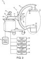
- a typical flat panel x-ray computed tomography system includes a source 2, a filter 4, a shutter/collimator 6, a detector 8 and an anti-scatter grid 10.
- the source 2 such as an x-ray tube anode emits x-rays.
- the x-ray filter 4 includes a beam shaper or filtration unit which filters the x-rays.
- the shutter/collimator 6 defines the extent of the beam of x-rays which pass through the subject and impact the detector.
- the source 2, the filter 4 and the shutter/collimator 6 are typically located on one arm or at the end of an arm of the system. However, other geometries, such as a ring, and the like are also contemplated.
- the detector 8 and anti-scatter grid 10 are typically located opposite the source 2, the filter 4 and the shutter/collimator 6 such as on another arm or the other end of the arm of the system.
- the collimator typically limits the cross section of the x-ray beams to the cross section of the detector or to an anatomical region of interest to limit the patient's exposure to x-rays.
- the x-ray detector 8 detects the x-rays passed through the subject in the field of view.
- the detector 8 typically includes an array of detector elements which detect x-rays in areas each corresponding to a pixel.
- the anti-scatter grid 10 such as an assembly of lamellae or plates, typically perpendicular to the detector surface, limits the impact of scatter in images.
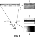
- FIGURE 2 a projection image at one gantry position of a typical air calibration scan is shown.
- the air calibration scan measures at each detector element or pixel, the intensity of the x-ray received from the source 2.
- the air calibration projection images are generated for a number of gantry orientations.
- the projection image of FIGURE 2 shows a darken area on the right where the filter 4 is thinnest and the x-rays are most intense. The light area to the left indicates the thickest portion of the filter 4 where the x-rays are the least intense.
- the air calibration image has a series of evenly spaced thin white lines where the lamellae of the anti-scatter grid block the x-rays and cast shadows on the detector.
- the air projection image is representative of an off-center detector such as FIGURE 1 . An air calibration projection image from a system with a symmetric detector would show light areas at both ends with the intense area centered.
- the system includes a gantry 15, which in this example includes a "C" shaped arm 16.
- the system includes elements 18 disposed at opposite ends of the C-arm 16.
- the system elements 18 include the source 2, the filter 4, the shutter/collimator 6 disposed at one end, and the detector 8 and anti-scatter grid 10 disposed at the opposite end.
- the C-arm is attached to a horizontal arm 20 which has a pivot 22.
- a drive (not visible) rotates the C-arm 16 along a trajectory 24 around an axis of the pivot to move the source and detector assemblies typically by 360 0 around an imaging area between opposite ends of the C-arm.
- the region of the patient to be imaged is supported on a patient table or support in the imaging area.
- the C-arm 16 is mounted in a slide 25 in the horizontal arm which carries a drive (not visible) for moving the C-arm along a trajectory 26 to selectively image the subject over about 180 0 of projection directions.
- Calibration information is obtained by processing one or more calibration acquisitions. The calibration information is used to correct images acquired during the scan of a subject such as in the creation of tomographic cross-sectional images.
- the system elements 18 generate and detect x-rays which pass through the imaging area.
- the x-rays detected by the detector are communicated to a decomposition unit 28 connected via circuitry in the gantry.
- the decomposition unit 28 can be embodied by one or more processors.
- x-ray data is received by the system elements and transmitted to the decomposition unit.
- the decomposition unit uses air scan acquisitions and optionally processing results from geometric phantom acquisitions to decompose a selection of projection images into relative positions of each of the elements for the different gantry orientations.
- the relative positions are based on ideal positions in a system with no deformation or misalignment compared to their target position obtained from design information.
- a reference unit 29 stores and maintains the reference images and other data such as design information, system maintenance information, and the like.
- the system includes a display device 30 and at least one input device 32.
- a healthcare practitioner can control the operation of the system through the input device 32.
- the display device 30 displays the images, menus, panels, and user controls and includes one or more of a LCD display, an LED display, a plasma display, a projection display, a touch screen display, and the like.
- the display device and the input device can operate as part of a computer such as a desktop computer, a laptop, a tablet, a mobile computing device, a smartphone, and the like.
- the input device can be a keyboard, a mouse, a microphone, and the like.
- the system can include a storage device 34 such as memory, disk, network attached storage and the like.
- Reference scans including projection images are stored and maintained by the reference unit or memory 29.
- x-ray projection data is received by the system elements and transmitted to the correction unit.
- One or more sensors 36 provide data with the x-ray projection data such as operating temperatures, strain measurements, gantry positional measurements, system wear measurements and the like.
- a sensor can be implemented by an analysis of the x-ray projection data to determine and update positional measurements.
- the measurement unit 37 receives the measurement data and determines the relative positions of each of the elements based on the measured data.
- Other data can be included with the x-ray projection data from the reference unit 29 such as expected mechanical drift based on history of the system or system type, engineering specifications, manufacturer based reference scans, and the like.
- a correction unit 38 generates a correction for each position for each of the system elements.
- the correction unit can store the generated corrections in the storage device 34 or calculate them in real time or retroactively.
- the corrections for each gantry orientation and each element can include overlays or vector translations for each element or portion of an element typically expressed in detector pixels, intensity adjustments, and the like.
- the combined corrections form a uniformity correction.
- a reconstruction unit 39 reconstructs images using the received x-ray data which includes projection data, sensor data, and the like from the decomposition unit 28 and corrected by the correction unit 38.
- the uniformity correction can be generated as an entire or relative adjustment by the correction unit.
- the reconstruction unit 39 uses a uniformity correction based on the combined corrections of each element for the different gantry orientations from the correction unit 38.
- the various units are suitably embodied by an electronic data processing device, such as the electronic processor or electronic processing device of the decomposition unit, or by a network-based server computer operatively connected with the system by a network, or so forth.
- the disclosed calibration techniques are suitably implemented as a non-transitory storage medium storing instructions (e.g., software) readable by an electronic data processing device and executable by the electronic data processing device to perform the disclosed calibration techniques.
- FIGURE 4 diagrammatically illustrates one embodiment of image projection data used to decompose system element motion.
- Acquired air scan calibration projection images such as shown in FIGURE 2 are decomposed into calibration projection images for each element such as a filter air scan projection image 38, a shutter air scan projection image 40, and an anti-scatter grid air scan projection image 42.
- the decomposition makes use of known image processing techniques, taking known properties of the system components into account, such as their spatial scale or repeated spatial patterns.
- separate air scan projection images of the system components can be created as part of the initial manufacturing process. The separate calibration images can then be updated from the decomposition of air scan calibration projection images, e.g. daily, before each patient, etc.
- the filter scan projection image 40 shows the non-uniform nature of the filter 4.
- the illustrated filter is asymmetric and shows a greater intensity on the right which tapers to the left and tapers most strongly to the lower left.
- An example shutter scan projection image 42 shows the intensity greatest in the center. Although not readily visible to the normal eye, inconsistencies in the edges of the shutter, and collimator, if present, are revealed in the image.
- the anti-scatter grid air scan projection image 44 shows uniformly spaced lines where the lamellae or grid cast shadows on the detector. Shifting of the lamellae relative to the detector or shifting of the x-ray source relative to the lamellae shifts the lines.
- each element is separated or decomposed using sensor information for its current position. For example, when this sensor is implemented using image analysis, then a least squares error minimization can be used to determine the relative placement and orientation of the lamellae based on the individual pixels values of an initial air scan calibration projection images and/or the known geometry of the anti scatter grid and a subsequent air scan at different gantry positions.
- the multi-layer decomposition measures the detected position of the anti-scatter grid based, for example, on the lines and shadows in the air scan calibration projection image. Similar decomposition is performed for the filter and shutter/collimator.
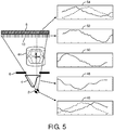
- FIGURE 5 diagrammatically illustrates an embodiment of the system and decomposed system element motion.
- a geometric phantom 44 is used to calibrate the positions of some elements 18 such as the source 2 and detector 8 elements, e.g., relative to an isocenter of the scanner.
- the information from a geometric phantom can be used to further refine or correct the relative positions of each element.
- an anti-scatter grid is firmly attached to the detector, but the grid can change its location relative to the focal spot of the source.
- the filter or beam shaper is attached to the tube or source housing with mechanics of known degrees of freedom and positioning accuracy.
- the movement of each element relative to a center can be determined from the data such as the air scan calibration projection images, geometric calibration projection images, imaging of a subject, sensors, etc.
- image features from imaging of a subject can be measured that capture the position of the individual elements.
- Artifact effects such as due to the anti-scatter grid lamellae, the beam shaper profile, or the collimator edges can be removed from the image.
- the decomposition can be shown graphically for each element with the y-axis as the deviation from the ideal center or offset, and the x-axis representing the gantry rotation angle determined from a variety of sources such as positional sensors, geometric phantoms, and the like.
- Air and geometric projection images are generated at each angular step, performing the geometric calibration scan first and the air calibration scan after removing the geometric calibration phantom from the x-ray system.
- the air projection images at each angular step or a subset of angular steps are stored in a memory 34.
- ideal air projection images of each system element are generated using system knowledge and image simulation methods.
- Geometric calibration information i.e., the positions of the x-ray source and detector relative to an isocenter for each requested gantry position, are derived from the geometric calibration scan and stored as well.
- one or more reference images representing one or more system elements are selected from the ideal air projection images, the subset of air projection images stored in memory 34 , or the air projection image acquired at this angular step.
- the decomposition unit 28 generates calibration data.
- the decomposition unit 28 uses image processing analysis methods to determine the combination of air projection images for each system element and geometric transformations of these air projection images that best represent the air projection image acquired at each angular step.
- the determined combination of air projection images and geometric transformations are used to generate calibration data.
- the calibration data can be stored as a set of one or more air calibration projection images for each system element as shown in FIGURE 4 together with the geometric transformations for each angular step.
- the determined parameters of the geometric transformation and their change over the course of a gantry rotation are represented by the graphs in FIGURE 5 .
- the correction unit 38 selects the air projection images for each system element and gantry position, executes the geometric transformations determined by the decomposition unit 28 during calibration, and performs the uniformity correction of the subject projection images with these correction images.
- the geometric transformation parameters can be obtained during calibration and updated during subject imaging using data obtained from external sensors or the subject imaging itself.
- the differences between geometric transformation parameters during calibration and during the acquisition of a subject can be determined using other measurements.
- the element positions are a function of the reference measurement and the difference between the reference image and the images at each gantry orientation. For example, an increase in operating temperature of the arm may cause expansion which causes a difference in relative movement of an element.
- System wear on the lateral track may change the relative position of elements depending on the weights of elements on each arm. System wear can be considered in the differences between the reference image and the images at each orientation or can include measured system wear from sensors, operational time tables and the like.
- the positional adjustments to the reference image at each orientation can be stored in memory.
- the correction unit 38 or processor receives the shift or positional change information from the decomposition unit 28 , combines the attenuation corrections attributable to each element, e.g. the inverse of images with adjustments based on current measurements.
- the correction unit adjusts the reference uniformity correction accordingly and stores it in a memory.
- the air scan correction corresponding to the gantry orientation is retrieved from the memory by the reference unit or recalculated by the correction unit using the current information from the measurement unit.
- the correction can be improved by determining relative shifts of system components from the projection images of the patient scan and using those shifts to generate more accurate correction images.
- the correction improvement uses known image processing methods which take the known geometrical characteristics of the system components into account.
- the uniformity correction projection images can be displayed on the display unit 30 or stored in a memory or data storage such as a Picture Archiving and Communication System (PACS), Radiology Information System, and the like.
- the reconstruction unit or processor 39 reconstructs the projection images into one or more images such as slice images, 2D images, 3D images, digital reconstructed radiographs, and the like.
- x-ray calibration data is received.
- the x-ray calibration data can include an air scan calibration projection images, and geometric scan calibration projection images received by the decomposition unit.
- the x-ray calibration data can include data from one or more sensors such as strain gauges, temperature sensors, positional sensors, and the like received by the measurement unit.
- the x-ray calibration data can include system wear effects, temperature effects, gantry orientations, expected mechanical drift, system specifications, and manufacturing scans stored and maintained by the reference unit.
- the x-ray calibration data is decomposed in a step 62 using a multi-layer decomposition, which generates projection images specific to each element.
- the air scan projection image of FIGURE 2 can be decomposed to generate the projection images of FIGURE 4 specific to each element.
- the projection images of each element can be stored as reference projection images or as updates to existing reference projection images.
- a step 64 the projection images for each element from the decomposition are combined with other x-ray calibration data to determine the reference positions of each element.
- the reference positions for each element can be represented as graphs such as FIGURE 5 .
- the determined reference positions can include translation and rotation for each position in the range of motion of the gantry.
- the changes in the positions of each element with gantry angle can be stored in the storage device.
- subject x-ray data is received.
- the subject x-ray data includes image projection data with a subject received by the decomposition unit.
- the subject x-ray data can include data from one or more sensors such as strain gauges, temperature sensors, positional sensors, and the like received by the measurement unit.
- the subject x-ray image projection data is decomposed using a multi-layer decomposition in a step 68 similar to the decomposition of the calibration x-ray data.
- the decomposition generates projection images specific to each element.
- the system uses the decomposition projection images, subject x-ray data, and reference information from the reference unit such as the reference position of each element to determine the actual position of each element.
- x-ray data of a subject or image regions adjacent to the subject can be decomposed into effects by individual elements based on prior reference scans from the reference unit and current measurements from the measurement unit or based on image-processing methods.
- the lines can be used to compute a relative difference between the estimated lamellae shadow pattern and the actual pattern. The same comparison can be performed for each element to yield a set of variances for the plurality of elements.
- the actual position of each element can be used to update the reference position in a step 72 or recorded to further analysis on the performance of the system.
- the comparison of the reference scan adjusted by the measurements can be further adjusted based on decomposition of a projection of a current projection image which includes the subject.
- a uniformity correction is generated in a step 74 from the actual position or the reference position of each element.
- the correction can be dynamically updated during the imaging process such as using the set of variances dynamically with x-ray data of a subject or with retrieval of reference relative positions from the reference unit adjusted with measurements from the measurement unit.
- the correction can include an intensity adjustment or uniformity correction value.
- the corrections are constructed using an overlay for each element which includes a relative adjustment in intensity by each element for a volume location.
- a step 76 reconstruction of a projection image or images with the subject is performed using the subject x-ray data modified with the generated correction.
- the correction corrects the attenuation used to reconstruct a projection image or images of a subject by correcting for non-uniformity effects in the measurement.
- the reconstruction reconstructs images such as the 2D projection images into a 3D volume image. Slice images, surface rendering images and the like derived from the 3D volume image can be displayed on a display device and/or stored in a data storage or memory.
- a decision step reflects the operation of steps such that calibration scans are periodically performed such as before each patient, daily, weekly, monthly, etc. Even with performing a calibration scan before scanning each subject, one or more scans with the subject or subjects can occur between calibration scans.
Claims (14)
- Ein Röntgen-Computertomographiesystem (14), das Folgendes umfasst:eine Gantry (15), die sich in verschiedene Ausrichtungen bewegt und Röntgendaten generiert, die Bildprojektionsdaten für mehrere der Ausrichtungen umfassen;mehrere Elemente (18), die mit der Gantry verbunden sind und eine Röntgenabschwächung der generierten Projektionsdaten verursachen, wobei die Elemente eine Röntgenquelle (2), einen Röntgenfilter (4), einen Verschluss/Kollimator (6), einen Röntgendetektor (8) und ein Streustrahlenraster (10) umfassen;mindestens einen Prozessor (28), der für folgende Schritte programmiert ist:Abrufen (60) der generierten Röntgendaten, die Bildprojektionsdaten für die einzelnen Gantry-Ausrichtungen rund um die Bildgebungsregion umfassen;wobei die generierten Röntgendaten Messungen der dem abzubildenden Objekt zuzurechnenden Abschwächung sowie der den mehreren Elementen zuzurechnenden Abschwächung umfassen, wobei sich die Messungen der den mehreren Elementen zuzurechnenden Abschwächung mit den verschiedenen Gantry-Ausrichtungen ändern,Zerlegen (62) der abgerufenen Bildprojektionsdaten, um die relativen Positionen der Elemente bei mindestens einer Gantry-Ausrichtung abzuleiten, wobei jedes der Elemente eine Röntgenabschwächung verursacht, die den Elementen in den abgerufenen Bildprojektionsdaten zuzurechnen ist, undGenerieren (74) einer Korrektur der gemessenen Abschwächungen anhand der relativen Positionen der Elemente.
- Das System (14) gemäß Anspruch 1, wobei der mindestens eine Prozessor zudem für folgende Schritte programmiert ist:Abrufen (60) von Röntgendaten, die Bildprojektionsdaten des Objekts umfassen, und die den verschiedenen Ausrichtungen entsprechen;Korrigieren (64) der Bildprojektionsdaten des Patienten für die einzelnen Ausrichtungen im Rahmen einer entsprechenden Korrektur der gemessenen Abschwächung anhand der relativen Positionen der Elemente für die verschiedenen Ausrichtungen;Rekonstruieren (66) der korrigierten Objekt-Bildprojektionsdaten als 3D-Bilddarstellung.
- Das System (14) gemäß einem der Ansprüche 1 bis 2, das zudem Folgendes umfasst:
mindestens einen Sensor (36), der die Bewegung der einzelnen Elemente misst, wobei die generierten Röntgendaten die gemessene Bewegung enthalten. - Das System (14) gemäß einem der Ansprüche 1 bis 3, wobei der Prozessor zudem für folgenden Schritt programmiert ist:
Generieren einer Reihe von Korrekturüberlagerungen, die den relativen Positionen der Elemente entsprechen, wobei sich die Ausrichtung der Überlagerungen mit den Änderungen der relativen Positionen der Elemente verschiebt. - Das System (14) gemäß einem der Ansprüche 1 bis 4, das zudem Folgendes umfasst:
eine Messeinheit (37), die Messungen von mehreren Sensoren abruft und die relative Position der Elemente für die verschiedenen Ausrichtungen der Gantry anhand der abgerufenen Messungen berechnet. - Das System (14) gemäß einem der Ansprüche 1 bis 5, das zudem Folgendes umfasst:
eine Referenzeinheit (39), die anhand der Gantry-Ausrichtung der einzelnen Elemente mindestens eines der folgenden Elemente bereitstellt:Luftprojektionsbilder für die einzelnen Elemente;geometrische Kalibrierungsdaten für die einzelnen Elemente; unddie relativen Verschiebungen der einzelnen Elemente nach Konstruktion, Temperatur, Systemverschleißindikatoren und Zeit. - Das System (14) gemäß einem der Ansprüche 1 bis 6, das zudem Folgendes umfasst:
eine Korrektureinheit (38), die anhand der zerlegten Positionen der Elemente für die einzelnen Gantry-Ausrichtungen eine Korrektur der gemessenen Abschwächung durchführt. - Eine auf einem Prozessor umgesetzte Methode für die Röntgen-Computertomographie-Kalibrierung, die folgende Schritte umfasst:Abrufen (60) von Röntgendaten, die Bildprojektionsdaten für die einzelnen Gantry-Ausrichtungen rund um die Bildgebungsregion umfassen;wobei die Röntgendaten Messungen der dem abzubildenden Objekt zuzurechnenden Abschwächung sowie der den mehreren Elementen zuzurechnenden Abschwächung umfassen, wobei sich die Messungen der den mehreren Elementen zuzurechnenden Abschwächung mit den verschiedenen Gantry-Ausrichtungen ändern,Zerlegen (62) der abgerufenen Bildprojektionsdaten, um die relativen Positionen der Elemente bei mindestens einer Gantry-Ausrichtung abzuleiten, wobei jedes der Elemente eine Röntgenabschwächung verursacht, die den Elementen in den abgerufenen Bildprojektionsdaten zuzurechnen ist, und wobei die Elemente eine Röntgenquelle (2), einen Röntgenfilter (4), einen Verschluss/Kollimator (6), einen Röntgendetektor (8) und ein Streustrahlenraster (10) umfassen; undGenerieren (74) einer Korrektur der gemessenen Abschwächungen anhand der relativen Positionen der Elemente.
- Die Methode gemäß Anspruch 8, das zudem Folgendes umfasst:Abrufen (66) von Röntgendaten für das Objekt, die Bildprojektionsdaten für die verschiedenen Ausrichtungen umfassen;Korrigieren (74) der Bildprojektionsdaten des Objekts für die einzelnen Ausrichtungen anhand der relativen Positionen der Elemente;Rekonstruieren (76) der korrigierten Objekt-Bildprojektionsdaten als 3D-Bilddarstellung.
- Die Methode gemäß einer der Ansprüche 8 und 9, das zudem Folgendes umfasst:Durchführen (40,42,44) einer Luftkalibrierungsabtastung, um für die einzelnen Gantry-Ausrichtungen Luftprojektionsreferenzbilder zu generieren.Durchführen eines geometrischen Kalibrierungsscans zum Messen der relativen Position mindestens einer Röntgenquelle und eines Röntgendetektors für die einzelnen Gantry-Ausrichtungen;Zerlegen (62) der Luftprojektionsreferenzbilder, um Elementreferenzbilder für mindestens einen Röntgenfilter, einen Röntgenverschluss/-Kollimator und ein Streustrahlenraster zu generieren;Ermitteln (64) der relativen Position des Röntgenfilters, des Röntgenverschlusses/-Kollimators, des Streustrahlenrasters, der Röntgenquelle und des Röntgendetektors für die einzelnen Gantry-Ausrichtungen anhand der zerlegten Elementreferenzbilder und des geometrischen Kalibrierungsscans.Korrigieren (74) der Bildprojektionsdaten des Objekts im Rahmen einer Korrektur der gemessenen Abschwächung anhand der zerlegten relativen Positionen des Röntgenfilters, des Röntgenverschlusses/-Kollimators, des Streustrahlenrasters, der Röntgenquelle und des Röntgendetektors; undRekonstruieren (76) der korrigierten Objekt-Bildprojektionsdaten als 3D-Bild.
- Die Methode gemäß einem der Ansprüche 8 bis 10, wobei das Zerlegen folgenden Schritt umfasst:
Berechnen des Abstands und der Ausrichtung der einzelnen Elemente (18) relativ zu einer Referenzposition für die einzelnen Ausrichtungen der Gantry (15) anhand der Luft- und geometrischen Kalibrierungsscans. - Die Methode gemäß einem der Ansprüche 8 bis 11, wobei das Zerlegen zudem folgenden Schritt umfasst:
Anpassen der relativen Position mindestens eines Elements (18) anhand von mindestens einer Messung des Sensors (36). - Die Methode gemäß einem der Ansprüche 8 bis 12, wobei das Generieren der Korrektur für die Abschwächungsmessung folgenden Schritt umfasst:
Konstruieren einer Intensitätsanpassung der Bildprojektionsdaten für die einzelnen Elemente anhand der zerlegten relativen Position des Elements. - Die Methode gemäß einem der Ansprüche 8 bis 13, wobei das Generieren der Korrektur für die Abschwächungsmessung folgende Schritte umfasst:Erstellen von Korrekturüberlagerungen für die einzelnen Elemente;Verschieben der Überlagerungen gemäß den relativen Positionen der Elemente,um für alle Gantry-Ausrichtungen eine Korrektur zu erhalten.
Applications Claiming Priority (2)
| Application Number | Priority Date | Filing Date | Title |
|---|---|---|---|
| US201261655602P | 2012-06-05 | 2012-06-05 | |
| PCT/IB2013/054003 WO2013182928A1 (en) | 2012-06-05 | 2013-05-16 | Motion layer decomposition calibration of x-ray ct imagers |
Publications (2)
| Publication Number | Publication Date |
|---|---|
| EP2854645A1 EP2854645A1 (de) | 2015-04-08 |
| EP2854645B1 true EP2854645B1 (de) | 2021-10-06 |
Family
ID=48793324
Family Applications (1)
| Application Number | Title | Priority Date | Filing Date |
|---|---|---|---|
| EP13737381.7A Active EP2854645B1 (de) | 2012-06-05 | 2013-05-16 | Bewegungsschichtzerlegungungskalibrierung von röntgen-ct-bildgebungsvorrichtungen |
Country Status (6)
| Country | Link |
|---|---|
| US (1) | US9636079B2 (de) |
| EP (1) | EP2854645B1 (de) |
| JP (1) | JP6316283B2 (de) |
| CN (1) | CN104334081B (de) |
| RU (1) | RU2014154006A (de) |
| WO (1) | WO2013182928A1 (de) |
Families Citing this family (27)
| Publication number | Priority date | Publication date | Assignee | Title |
|---|---|---|---|---|
| EP2961320B1 (de) * | 2013-03-01 | 2017-01-18 | Analogic Corporation | Verstärkungskalibrierung und -korrektur in einem strahlungssystem |
| EP2997899B1 (de) | 2014-09-17 | 2018-03-28 | Bruker microCT NV | Röntgen CT-Vorrichtung mit einem Filterelement mit maximaler Absorption in der Mitte |
| RU2700470C2 (ru) * | 2014-10-01 | 2019-09-17 | Конинклейке Филипс Н.В. | Устройство и способ визуализации |
| US10722200B2 (en) * | 2015-06-04 | 2020-07-28 | Siemens Healthcare Gmbh | Apparatus and methods for a projection display device on X-ray imaging devices |
| US10842453B2 (en) * | 2016-02-03 | 2020-11-24 | Globus Medical, Inc. | Portable medical imaging system |
| CN109688930A (zh) * | 2016-09-08 | 2019-04-26 | 皇家飞利浦有限公司 | 用于x射线成像的源光栅 |
| US10507005B2 (en) * | 2016-09-22 | 2019-12-17 | General Electric Company | Spectral calibration of spectral computed tomography (CT) |
| EP3559911B1 (de) * | 2016-12-21 | 2020-05-20 | Koninklijke Philips N.V. | Redundanzgewichtung für röntgentomographie mit exzentrischem detektor mit kurzer abtastung |
| FI20175244L (fi) * | 2017-03-17 | 2018-09-18 | Planmeca Oy | Itsekalibroiva lääketieteellinen kuvannuslaite |
| CN107015267B (zh) * | 2017-06-09 | 2018-10-09 | 河北格物仪器设备有限公司 | 探测器增益校正系统及方法 |
| US10610191B2 (en) * | 2017-07-06 | 2020-04-07 | Prismatic Sensors Ab | Managing geometric misalignment in x-ray imaging systems |
| EP3459463A1 (de) * | 2017-09-26 | 2019-03-27 | Koninklijke Philips N.V. | Vorrichtung und verfahren zum bestimmen eines volumens von projektion eines zweiachsigen computertomografiesystems |
| CN115153608A (zh) * | 2017-11-08 | 2022-10-11 | 上海联影医疗科技股份有限公司 | 校正投影图像的系统和方法 |
| WO2019090541A1 (en) * | 2017-11-08 | 2019-05-16 | Shenzhen United Imaging Healthcare Co., Ltd. | Systems and methods for correcting projection images in computed tomography image reconstruction |
| US10922855B2 (en) * | 2017-11-30 | 2021-02-16 | Shanghai United Imaging Healthcare Co., Ltd. | Systems and methods for determining at least one artifact calibration coefficient |
| IT201800000868A1 (it) * | 2018-01-15 | 2019-07-15 | Ims Giotto S P A | Metodo di calibrazione di un collimatore e apparecchiatura per analisi a raggi x configurata per effettuare tale metodo. |
| JP2019158534A (ja) * | 2018-03-12 | 2019-09-19 | 株式会社ミツトヨ | 計測用x線ct装置、及び、その断層画像生成方法 |
| EP3545844A1 (de) | 2018-03-27 | 2019-10-02 | Koninklijke Philips N.V. | Vorrichtung, system und verfahren zur steuerung einer position eines streustrahlenrasters in einem röntgenbilderfassungssystem |
| CN108634976B (zh) * | 2018-04-27 | 2022-09-02 | 东软医疗系统股份有限公司 | 一种图像校正方法和装置 |
| WO2020010842A1 (zh) * | 2018-07-12 | 2020-01-16 | 西安大医集团有限公司 | 放疗设备等中心与治疗等中心一致性检测方法和系统 |
| DE102018211669B4 (de) * | 2018-07-12 | 2020-01-23 | Siemens Healthcare Gmbh | Omnidirektionales Fahrwerk für eine Gantry eines Computertomographiegeräts |
| WO2020029148A1 (zh) | 2018-08-08 | 2020-02-13 | 西安大医集团有限公司 | 一种放疗设备准直器校正方法及装置 |
| CN111096761B (zh) * | 2018-10-29 | 2024-03-08 | 上海西门子医疗器械有限公司 | 修正楔形滤波器散射的方法、装置和相关设备 |
| DE102019203713A1 (de) | 2019-03-19 | 2020-09-24 | Siemens Healthcare Gmbh | Korrektur einer Unwucht anhand der aufgenommenen Strahlungsdaten |
| EP3721809A1 (de) | 2019-04-10 | 2020-10-14 | Koninklijke Philips N.V. | Kalibrierung von statischer verstärkung |
| JP7392481B2 (ja) * | 2020-01-14 | 2023-12-06 | コニカミノルタ株式会社 | 撮影支援装置、放射線撮影システム及びプログラム |
| CN111728632B (zh) * | 2020-07-31 | 2023-08-15 | 上海联影医疗科技股份有限公司 | 射线探测装置、射线探测方法和ct图像重建方法 |
Family Cites Families (39)
| Publication number | Priority date | Publication date | Assignee | Title |
|---|---|---|---|---|
| US4288695A (en) * | 1979-04-13 | 1981-09-08 | Technicare Corporation | Computerized tomographic scanner with shaped radiation filter |
| US6044132A (en) * | 1997-12-31 | 2000-03-28 | Siemens Corporate Research, Inc. | Apparatus for providing markers on an image, for use in conjunction with C-arm calibration apparatus |
| JP2000014664A (ja) * | 1998-07-06 | 2000-01-18 | Toshiba Corp | X線診断装置及び放射線診断装置 |
| JP4314645B2 (ja) * | 1998-07-17 | 2009-08-19 | 株式会社島津製作所 | X線ct装置 |
| US6092928A (en) * | 1998-11-12 | 2000-07-25 | Picker International, Inc. | Apparatus and method to determine the relative position of a detector array and an x-ray tube focal spot |
| US6379043B1 (en) * | 1998-12-08 | 2002-04-30 | U.S. Philips Corporation | X-ray examination apparatus and method for generating distortion-free X-ray images |
| DE19856537A1 (de) * | 1998-12-08 | 2000-06-15 | Philips Corp Intellectual Pty | Verfahren zur intraoperativen Kalibration von C-Bogen Röntgenanordnungen |
| DE19936408B4 (de) * | 1999-08-03 | 2005-09-01 | Siemens Ag | Verfahrbares Röntgengerät |
| US6533455B2 (en) * | 2000-08-31 | 2003-03-18 | Siemens Aktiengesellschaft | Method for determining a coordinate transformation for use in navigating an object |
| DE10202091B4 (de) * | 2002-01-21 | 2005-09-08 | Siemens Ag | Vorrichtung zur Ermittlung einer Koordinatentransformation |
| DE10215808B4 (de) * | 2002-04-10 | 2005-02-24 | Siemens Ag | Verfahren zur Registrierung für navigationsgeführte Eingriffe |
| US7065393B2 (en) * | 2002-07-11 | 2006-06-20 | Cedara Software Corp. | Apparatus, system and method of calibrating medical imaging systems |
| US6950493B2 (en) * | 2003-06-25 | 2005-09-27 | Besson Guy M | Dynamic multi-spectral CT imaging |
| WO2005015125A1 (en) * | 2003-08-08 | 2005-02-17 | University Health Network | Method and system for calibrating a source and detector instrument |
| US7016456B2 (en) | 2003-10-31 | 2006-03-21 | General Electric Company | Method and apparatus for calibrating volumetric computed tomography systems |
| JP4700930B2 (ja) * | 2004-05-28 | 2011-06-15 | ジーイー・メディカル・システムズ・グローバル・テクノロジー・カンパニー・エルエルシー | 放射線断層撮影装置および検出器素子位置ズレ量測定装置 |
| JP2006000225A (ja) * | 2004-06-15 | 2006-01-05 | Canon Inc | X線ct装置 |
| US7224763B2 (en) * | 2004-07-27 | 2007-05-29 | Analogic Corporation | Method of and system for X-ray spectral correction in multi-energy computed tomography |
| FR2879433B1 (fr) * | 2004-12-17 | 2008-01-04 | Gen Electric | Procede pour determiner une geometrie d'acquisition d'un systeme medical |
| US7391844B2 (en) * | 2005-01-14 | 2008-06-24 | General Electric Company | Method and apparatus for correcting for beam hardening in CT images |
| US7844094B2 (en) * | 2005-04-29 | 2010-11-30 | Varian Medical Systems, Inc. | Systems and methods for determining geometric parameters of imaging devices |
| US7950849B2 (en) * | 2005-11-29 | 2011-05-31 | General Electric Company | Method and device for geometry analysis and calibration of volumetric imaging systems |
| DE102006008042A1 (de) * | 2006-02-21 | 2007-07-19 | Siemens Ag | Medizinisches Gerät mit im medizinischen Gerät kombinierter Bilderfassungs- und Positionsbestimmungsvorrichtung |
| JP2008154753A (ja) * | 2006-12-22 | 2008-07-10 | Canon Inc | コーンビーム放射線撮影画像処理装置 |
| US8000522B2 (en) * | 2007-02-02 | 2011-08-16 | General Electric Company | Method and system for three-dimensional imaging in a non-calibrated geometry |
| DE102007021185B4 (de) * | 2007-05-05 | 2012-09-20 | Ziehm Imaging Gmbh | Röntgendiagnostikeinrichtung mit einer Vielzahl kodierter Marken und ein Verfahren zur Bestimmung der Lage von Einrichtungsteilen der Röntgendiagnostikeinrichtung |
| DE102007042333A1 (de) * | 2007-09-06 | 2009-03-12 | Siemens Ag | Verfahren zum Ermitteln einer Abbildungsvorschrift und Verfahren zum Erzeugen einer 3D-Rekonstruktion |
| RU2359614C1 (ru) | 2007-10-31 | 2009-06-27 | Закрытое Акционерное Общество "Импульс" | Способ калибровки цифрового рентгеновского аппарата (варианты) |
| EP2098168B1 (de) * | 2008-03-04 | 2010-11-03 | BrainLAB AG | Kalibrierung eines C-Bogen-Röntgengeräts |
| EP2156790B1 (de) * | 2008-08-22 | 2012-03-28 | BrainLAB AG | Zuordnung von Röntgenmarkern zu im Röntgenbild abgebildeten Bildmarkern |
| JP2010184086A (ja) * | 2009-02-13 | 2010-08-26 | Canon Inc | 放射線ct装置及びその制御方法 |
| JP5584995B2 (ja) | 2009-04-15 | 2014-09-10 | 株式会社島津製作所 | 放射線撮影装置およびキャリブレーションデータの取得方法 |
| JP5349174B2 (ja) * | 2009-07-02 | 2013-11-20 | 株式会社日立メディコ | X線ct装置及びx線検出器のx線検出素子間の距離を計測するための計測プログラム |
| JP5400546B2 (ja) * | 2009-09-28 | 2014-01-29 | 株式会社日立メディコ | X線ct装置 |
| US8611627B2 (en) * | 2009-12-23 | 2013-12-17 | General Electric Company | CT spectral calibration |
| US8262288B2 (en) * | 2010-01-21 | 2012-09-11 | Analogic Corporation | Focal spot position determiner |
| US8315352B2 (en) * | 2010-09-16 | 2012-11-20 | General Electric Company | System and method of spectral calibration and basis material decomposition for X-ray CT systems |
| DE102012204019B4 (de) * | 2012-03-14 | 2018-02-08 | Siemens Healthcare Gmbh | Verfahren zur Reduzierung von Bewegungsartefakten |
| US8958524B2 (en) * | 2013-01-31 | 2015-02-17 | Analogic Corporation | Correction of projection data in radiation system |
-
2013
- 2013-05-16 EP EP13737381.7A patent/EP2854645B1/de active Active
- 2013-05-16 US US14/401,130 patent/US9636079B2/en active Active
- 2013-05-16 RU RU2014154006A patent/RU2014154006A/ru unknown
- 2013-05-16 JP JP2015515605A patent/JP6316283B2/ja active Active
- 2013-05-16 WO PCT/IB2013/054003 patent/WO2013182928A1/en active Application Filing
- 2013-05-16 CN CN201380029896.XA patent/CN104334081B/zh active Active
Non-Patent Citations (1)
| Title |
|---|
| None * |
Also Published As
| Publication number | Publication date |
|---|---|
| JP2015518765A (ja) | 2015-07-06 |
| EP2854645A1 (de) | 2015-04-08 |
| CN104334081B (zh) | 2018-04-10 |
| RU2014154006A (ru) | 2016-08-10 |
| JP6316283B2 (ja) | 2018-04-25 |
| WO2013182928A1 (en) | 2013-12-12 |
| US9636079B2 (en) | 2017-05-02 |
| US20150103972A1 (en) | 2015-04-16 |
| CN104334081A (zh) | 2015-02-04 |
Similar Documents
| Publication | Publication Date | Title |
|---|---|---|
| EP2854645B1 (de) | Bewegungsschichtzerlegungungskalibrierung von röntgen-ct-bildgebungsvorrichtungen | |
| JP2015518765A5 (de) | ||
| US9380985B2 (en) | X-ray tomosynthesis imaging device and calibration method of an X-ray tomosynthesis imaging device | |
| EP2046203B1 (de) | Röntgenstrahl-detektorbereich-kalibrierung, die von der brechung der streustrahlung abhängt | |
| US10368824B2 (en) | X-ray CT device and processing device | |
| EP2213235B1 (de) | Verfahren zur kalibrierung eines digitalen röntgengeräts | |
| JP2015150185A (ja) | X線撮影システム及び画像処理方法 | |
| US20110075792A1 (en) | Radiography apparatus | |
| EP3835830B1 (de) | Systeme und methoden zur abschätzung einer brennpunktbewegung und zur berechnung einer entspechenden korrektur | |
| JP6394082B2 (ja) | X線検査装置 | |
| KR101284986B1 (ko) | 고해상도 토모신세시스 단면 영상의 재구성 방법 및 그 장치 | |
| US7111985B2 (en) | Method and system for measuring table sag | |
| JP2016087458A (ja) | X線コンピュータ断層撮影装置 | |
| JP2015167860A (ja) | X線コンピュータ断層撮影装置、位置ずれ特定方法、および位置ずれ特定プログラム | |
| US7949174B2 (en) | System and method for calibrating an X-ray detector | |
| JP7387814B2 (ja) | X方向及びy方向の両方向での焦点スポット運動の検出及び補正のためのシステム及び方法 | |
| JP2017189685A (ja) | 画像処理装置、x線撮影システム及び画像処理方法 | |
| KR20240042194A (ko) | 단층촬영술 이득 교정 및 영상 보정 | |
| JP2015019991A (ja) | 検出器モジュール位置測定方法および放射線断層撮影装置並びにプログラム | |
| JP2012217644A (ja) | 放射線治療システム、絞り画像解析装置及び制御プログラム |
Legal Events
| Date | Code | Title | Description |
|---|---|---|---|
| PUAI | Public reference made under article 153(3) epc to a published international application that has entered the european phase |
Free format text: ORIGINAL CODE: 0009012 |
|
| 17P | Request for examination filed |
Effective date: 20150105 |
|
| AK | Designated contracting states |
Kind code of ref document: A1 Designated state(s): AL AT BE BG CH CY CZ DE DK EE ES FI FR GB GR HR HU IE IS IT LI LT LU LV MC MK MT NL NO PL PT RO RS SE SI SK SM TR |
|
| AX | Request for extension of the european patent |
Extension state: BA ME |
|
| DAX | Request for extension of the european patent (deleted) | ||
| STAA | Information on the status of an ep patent application or granted ep patent |
Free format text: STATUS: EXAMINATION IS IN PROGRESS |
|
| 17Q | First examination report despatched |
Effective date: 20190702 |
|
| STAA | Information on the status of an ep patent application or granted ep patent |
Free format text: STATUS: EXAMINATION IS IN PROGRESS |
|
| RAP1 | Party data changed (applicant data changed or rights of an application transferred) |
Owner name: KONINKLIJKE PHILIPS N.V. Owner name: PHILIPS GMBH |
|
| GRAP | Despatch of communication of intention to grant a patent |
Free format text: ORIGINAL CODE: EPIDOSNIGR1 |
|
| STAA | Information on the status of an ep patent application or granted ep patent |
Free format text: STATUS: GRANT OF PATENT IS INTENDED |
|
| INTG | Intention to grant announced |
Effective date: 20210506 |
|
| GRAS | Grant fee paid |
Free format text: ORIGINAL CODE: EPIDOSNIGR3 |
|
| GRAA | (expected) grant |
Free format text: ORIGINAL CODE: 0009210 |
|
| STAA | Information on the status of an ep patent application or granted ep patent |
Free format text: STATUS: THE PATENT HAS BEEN GRANTED |
|
| AK | Designated contracting states |
Kind code of ref document: B1 Designated state(s): AL AT BE BG CH CY CZ DE DK EE ES FI FR GB GR HR HU IE IS IT LI LT LU LV MC MK MT NL NO PL PT RO RS SE SI SK SM TR |
|
| REG | Reference to a national code |
Ref country code: GB Ref legal event code: FG4D |
|
| REG | Reference to a national code |
Ref country code: CH Ref legal event code: EP Ref country code: AT Ref legal event code: REF Ref document number: 1435540 Country of ref document: AT Kind code of ref document: T Effective date: 20211015 |
|
| REG | Reference to a national code |
Ref country code: DE Ref legal event code: R096 Ref document number: 602013079542 Country of ref document: DE |
|
| REG | Reference to a national code |
Ref country code: IE Ref legal event code: FG4D |
|
| REG | Reference to a national code |
Ref country code: LT Ref legal event code: MG9D |
|
| REG | Reference to a national code |
Ref country code: NL Ref legal event code: MP Effective date: 20211006 |
|
| REG | Reference to a national code |
Ref country code: AT Ref legal event code: MK05 Ref document number: 1435540 Country of ref document: AT Kind code of ref document: T Effective date: 20211006 |
|
| PG25 | Lapsed in a contracting state [announced via postgrant information from national office to epo] |
Ref country code: RS Free format text: LAPSE BECAUSE OF FAILURE TO SUBMIT A TRANSLATION OF THE DESCRIPTION OR TO PAY THE FEE WITHIN THE PRESCRIBED TIME-LIMIT Effective date: 20211006 Ref country code: LT Free format text: LAPSE BECAUSE OF FAILURE TO SUBMIT A TRANSLATION OF THE DESCRIPTION OR TO PAY THE FEE WITHIN THE PRESCRIBED TIME-LIMIT Effective date: 20211006 Ref country code: FI Free format text: LAPSE BECAUSE OF FAILURE TO SUBMIT A TRANSLATION OF THE DESCRIPTION OR TO PAY THE FEE WITHIN THE PRESCRIBED TIME-LIMIT Effective date: 20211006 Ref country code: BG Free format text: LAPSE BECAUSE OF FAILURE TO SUBMIT A TRANSLATION OF THE DESCRIPTION OR TO PAY THE FEE WITHIN THE PRESCRIBED TIME-LIMIT Effective date: 20220106 Ref country code: AT Free format text: LAPSE BECAUSE OF FAILURE TO SUBMIT A TRANSLATION OF THE DESCRIPTION OR TO PAY THE FEE WITHIN THE PRESCRIBED TIME-LIMIT Effective date: 20211006 |
|
| PG25 | Lapsed in a contracting state [announced via postgrant information from national office to epo] |
Ref country code: IS Free format text: LAPSE BECAUSE OF FAILURE TO SUBMIT A TRANSLATION OF THE DESCRIPTION OR TO PAY THE FEE WITHIN THE PRESCRIBED TIME-LIMIT Effective date: 20220206 Ref country code: SE Free format text: LAPSE BECAUSE OF FAILURE TO SUBMIT A TRANSLATION OF THE DESCRIPTION OR TO PAY THE FEE WITHIN THE PRESCRIBED TIME-LIMIT Effective date: 20211006 Ref country code: PT Free format text: LAPSE BECAUSE OF FAILURE TO SUBMIT A TRANSLATION OF THE DESCRIPTION OR TO PAY THE FEE WITHIN THE PRESCRIBED TIME-LIMIT Effective date: 20220207 Ref country code: PL Free format text: LAPSE BECAUSE OF FAILURE TO SUBMIT A TRANSLATION OF THE DESCRIPTION OR TO PAY THE FEE WITHIN THE PRESCRIBED TIME-LIMIT Effective date: 20211006 Ref country code: NO Free format text: LAPSE BECAUSE OF FAILURE TO SUBMIT A TRANSLATION OF THE DESCRIPTION OR TO PAY THE FEE WITHIN THE PRESCRIBED TIME-LIMIT Effective date: 20220106 Ref country code: NL Free format text: LAPSE BECAUSE OF FAILURE TO SUBMIT A TRANSLATION OF THE DESCRIPTION OR TO PAY THE FEE WITHIN THE PRESCRIBED TIME-LIMIT Effective date: 20211006 Ref country code: LV Free format text: LAPSE BECAUSE OF FAILURE TO SUBMIT A TRANSLATION OF THE DESCRIPTION OR TO PAY THE FEE WITHIN THE PRESCRIBED TIME-LIMIT Effective date: 20211006 Ref country code: HR Free format text: LAPSE BECAUSE OF FAILURE TO SUBMIT A TRANSLATION OF THE DESCRIPTION OR TO PAY THE FEE WITHIN THE PRESCRIBED TIME-LIMIT Effective date: 20211006 Ref country code: GR Free format text: LAPSE BECAUSE OF FAILURE TO SUBMIT A TRANSLATION OF THE DESCRIPTION OR TO PAY THE FEE WITHIN THE PRESCRIBED TIME-LIMIT Effective date: 20220107 Ref country code: ES Free format text: LAPSE BECAUSE OF FAILURE TO SUBMIT A TRANSLATION OF THE DESCRIPTION OR TO PAY THE FEE WITHIN THE PRESCRIBED TIME-LIMIT Effective date: 20211006 |
|
| REG | Reference to a national code |
Ref country code: DE Ref legal event code: R097 Ref document number: 602013079542 Country of ref document: DE |
|
| PG25 | Lapsed in a contracting state [announced via postgrant information from national office to epo] |
Ref country code: SM Free format text: LAPSE BECAUSE OF FAILURE TO SUBMIT A TRANSLATION OF THE DESCRIPTION OR TO PAY THE FEE WITHIN THE PRESCRIBED TIME-LIMIT Effective date: 20211006 Ref country code: SK Free format text: LAPSE BECAUSE OF FAILURE TO SUBMIT A TRANSLATION OF THE DESCRIPTION OR TO PAY THE FEE WITHIN THE PRESCRIBED TIME-LIMIT Effective date: 20211006 Ref country code: RO Free format text: LAPSE BECAUSE OF FAILURE TO SUBMIT A TRANSLATION OF THE DESCRIPTION OR TO PAY THE FEE WITHIN THE PRESCRIBED TIME-LIMIT Effective date: 20211006 Ref country code: EE Free format text: LAPSE BECAUSE OF FAILURE TO SUBMIT A TRANSLATION OF THE DESCRIPTION OR TO PAY THE FEE WITHIN THE PRESCRIBED TIME-LIMIT Effective date: 20211006 Ref country code: DK Free format text: LAPSE BECAUSE OF FAILURE TO SUBMIT A TRANSLATION OF THE DESCRIPTION OR TO PAY THE FEE WITHIN THE PRESCRIBED TIME-LIMIT Effective date: 20211006 Ref country code: CZ Free format text: LAPSE BECAUSE OF FAILURE TO SUBMIT A TRANSLATION OF THE DESCRIPTION OR TO PAY THE FEE WITHIN THE PRESCRIBED TIME-LIMIT Effective date: 20211006 |
|
| PLBE | No opposition filed within time limit |
Free format text: ORIGINAL CODE: 0009261 |
|
| STAA | Information on the status of an ep patent application or granted ep patent |
Free format text: STATUS: NO OPPOSITION FILED WITHIN TIME LIMIT |
|
| 26N | No opposition filed |
Effective date: 20220707 |
|
| PG25 | Lapsed in a contracting state [announced via postgrant information from national office to epo] |
Ref country code: AL Free format text: LAPSE BECAUSE OF FAILURE TO SUBMIT A TRANSLATION OF THE DESCRIPTION OR TO PAY THE FEE WITHIN THE PRESCRIBED TIME-LIMIT Effective date: 20211006 |
|
| PG25 | Lapsed in a contracting state [announced via postgrant information from national office to epo] |
Ref country code: SI Free format text: LAPSE BECAUSE OF FAILURE TO SUBMIT A TRANSLATION OF THE DESCRIPTION OR TO PAY THE FEE WITHIN THE PRESCRIBED TIME-LIMIT Effective date: 20211006 |
|
| REG | Reference to a national code |
Ref country code: CH Ref legal event code: PL |
|
| REG | Reference to a national code |
Ref country code: BE Ref legal event code: MM Effective date: 20220531 |
|
| PG25 | Lapsed in a contracting state [announced via postgrant information from national office to epo] |
Ref country code: MC Free format text: LAPSE BECAUSE OF FAILURE TO SUBMIT A TRANSLATION OF THE DESCRIPTION OR TO PAY THE FEE WITHIN THE PRESCRIBED TIME-LIMIT Effective date: 20211006 Ref country code: LU Free format text: LAPSE BECAUSE OF NON-PAYMENT OF DUE FEES Effective date: 20220516 Ref country code: LI Free format text: LAPSE BECAUSE OF NON-PAYMENT OF DUE FEES Effective date: 20220531 Ref country code: CH Free format text: LAPSE BECAUSE OF NON-PAYMENT OF DUE FEES Effective date: 20220531 |
|
| PG25 | Lapsed in a contracting state [announced via postgrant information from national office to epo] |
Ref country code: IE Free format text: LAPSE BECAUSE OF NON-PAYMENT OF DUE FEES Effective date: 20220516 |
|
| PG25 | Lapsed in a contracting state [announced via postgrant information from national office to epo] |
Ref country code: IT Free format text: LAPSE BECAUSE OF FAILURE TO SUBMIT A TRANSLATION OF THE DESCRIPTION OR TO PAY THE FEE WITHIN THE PRESCRIBED TIME-LIMIT Effective date: 20211006 Ref country code: BE Free format text: LAPSE BECAUSE OF NON-PAYMENT OF DUE FEES Effective date: 20220531 |
|
| PGFP | Annual fee paid to national office [announced via postgrant information from national office to epo] |
Ref country code: FR Payment date: 20230523 Year of fee payment: 11 Ref country code: DE Payment date: 20220628 Year of fee payment: 11 |
|
| PGFP | Annual fee paid to national office [announced via postgrant information from national office to epo] |
Ref country code: GB Payment date: 20230523 Year of fee payment: 11 |
|
| REG | Reference to a national code |
Ref country code: DE Ref legal event code: R084 Ref document number: 602013079542 Country of ref document: DE |
|
| PG25 | Lapsed in a contracting state [announced via postgrant information from national office to epo] |
Ref country code: HU Free format text: LAPSE BECAUSE OF FAILURE TO SUBMIT A TRANSLATION OF THE DESCRIPTION OR TO PAY THE FEE WITHIN THE PRESCRIBED TIME-LIMIT; INVALID AB INITIO Effective date: 20130516 |